EP4400695A1 - Gas turbine intake for aircraft engine and method of inspection thereof - Google Patents
Gas turbine intake for aircraft engine and method of inspection thereof Download PDFInfo
- Publication number
- EP4400695A1 EP4400695A1 EP23184005.9A EP23184005A EP4400695A1 EP 4400695 A1 EP4400695 A1 EP 4400695A1 EP 23184005 A EP23184005 A EP 23184005A EP 4400695 A1 EP4400695 A1 EP 4400695A1
- Authority
- EP
- European Patent Office
- Prior art keywords
- swirl
- distal portion
- proximal portion
- path
- housing assembly
- Prior art date
- Legal status (The legal status is an assumption and is not a legal conclusion. Google has not performed a legal analysis and makes no representation as to the accuracy of the status listed.)
- Pending
Links
Images



Classifications
-
- F—MECHANICAL ENGINEERING; LIGHTING; HEATING; WEAPONS; BLASTING
- F02—COMBUSTION ENGINES; HOT-GAS OR COMBUSTION-PRODUCT ENGINE PLANTS
- F02C—GAS-TURBINE PLANTS; AIR INTAKES FOR JET-PROPULSION PLANTS; CONTROLLING FUEL SUPPLY IN AIR-BREATHING JET-PROPULSION PLANTS
- F02C7/00—Features, components parts, details or accessories, not provided for in, or of interest apart form groups F02C1/00 - F02C6/00; Air intakes for jet-propulsion plants
- F02C7/04—Air intakes for gas-turbine plants or jet-propulsion plants
-
- F—MECHANICAL ENGINEERING; LIGHTING; HEATING; WEAPONS; BLASTING
- F01—MACHINES OR ENGINES IN GENERAL; ENGINE PLANTS IN GENERAL; STEAM ENGINES
- F01D—NON-POSITIVE DISPLACEMENT MACHINES OR ENGINES, e.g. STEAM TURBINES
- F01D9/00—Stators
- F01D9/06—Fluid supply conduits to nozzles or the like
- F01D9/065—Fluid supply or removal conduits traversing the working fluid flow, e.g. for lubrication-, cooling-, or sealing fluids
-
- F—MECHANICAL ENGINEERING; LIGHTING; HEATING; WEAPONS; BLASTING
- F05—INDEXING SCHEMES RELATING TO ENGINES OR PUMPS IN VARIOUS SUBCLASSES OF CLASSES F01-F04
- F05D—INDEXING SCHEME FOR ASPECTS RELATING TO NON-POSITIVE-DISPLACEMENT MACHINES OR ENGINES, GAS-TURBINES OR JET-PROPULSION PLANTS
- F05D2220/00—Application
- F05D2220/30—Application in turbines
- F05D2220/32—Application in turbines in gas turbines
-
- F—MECHANICAL ENGINEERING; LIGHTING; HEATING; WEAPONS; BLASTING
- F05—INDEXING SCHEMES RELATING TO ENGINES OR PUMPS IN VARIOUS SUBCLASSES OF CLASSES F01-F04
- F05D—INDEXING SCHEME FOR ASPECTS RELATING TO NON-POSITIVE-DISPLACEMENT MACHINES OR ENGINES, GAS-TURBINES OR JET-PROPULSION PLANTS
- F05D2230/00—Manufacture
- F05D2230/72—Maintenance
-
- F—MECHANICAL ENGINEERING; LIGHTING; HEATING; WEAPONS; BLASTING
- F05—INDEXING SCHEMES RELATING TO ENGINES OR PUMPS IN VARIOUS SUBCLASSES OF CLASSES F01-F04
- F05D—INDEXING SCHEME FOR ASPECTS RELATING TO NON-POSITIVE-DISPLACEMENT MACHINES OR ENGINES, GAS-TURBINES OR JET-PROPULSION PLANTS
- F05D2240/00—Components
- F05D2240/10—Stators
- F05D2240/12—Fluid guiding means, e.g. vanes
- F05D2240/127—Vortex generators, turbulators, or the like, for mixing
Definitions
- the application relates generally to gas turbine engines and, more particularly, to a gas turbine intake thereof.
- an aircraft engine comprising : an exhaust conduit; at least one combustion engine having an exhaust gas outlet fluidly connected to the exhaust conduit; at least one gas turbine having a casing defining a radially outer limit of an annular gas path extending along and around a central axis, and at least one rotor having a shaft concentric to the central axis, a plurality of blades circumferentially interspaced from one another around the central axis and protruding from the shaft across the annular gas path; and a swirl housing assembly defining an intake to the gas turbine, the swirl housing assembly having a tangential inlet fluidly connecting the exhaust conduit, an annular outlet fluidly connecting the annular gas path, a swirl path extending around the central axis and between the tangential inlet and the annular outlet, the swirl housing assembly having a proximal portion defining a first portion of the swirl path, a distal portion defining a second portion of the swirl path, the proximal portion fastened to the distal
- a gas turbine intake comprising a swirl housing assembly having a tangential inlet fluidly connecting an exhaust conduit, an annular outlet defined around a central axis and fluidly connecting a turbine gas path, a swirl path extending around the central axis and between the tangential inlet and the annular outlet, the swirl housing assembly having a proximal portion defining a first portion of the swirl path, a distal portion defining a second portion of the swirl path, vanes located in the swirl housing assembly, the vanes circumferentially interspaced from one another relative the central axis and extending between the proximal portion and the distal portion, the proximal portion fastened to the distal portion via a plurality of fasteners, a gasket sandwiched between the proximal portion and the distal portion by the plurality of fasteners, the gasket extending in a radial plane relative the central axis, the proximal portion unfastenable from and separable from the distal portion
- a method of inspecting a gas turbine intake having a swirl housing assembly comprising : unfastening a proximal portion of the swirl housing assembly from a distal portion of the swirl housing assembly; separating the proximal portion of the swirl housing assembly from the distal portion of the swirl housing assembly; and inspecting a plurality of vanes of the swirl housing assembly via an access stemming from said separating.
- Fig. 1 illustrates an aircraft engine 10 of a type preferably provided for use in subsonic flight, generally comprising a combustion engine 12 in which compressed air is mixed with fuel and ignited delivering power and exhaust gasses.
- the exhaust gasses are collected from the combustion engine 12 and directed to a gas turbine 14.
- the gas turbine 14 can convert energy in the form of heat, pressure and/or velocity of the exhaust gasses into angular velocity of a rotor 15, and the rotor 15 can be used to direct power to one or more other device, such as a compressor 18, a propulsor 20 (e.g. propeller, fan), and/or an electric machine acting as a generator.
- the transfer of power can be direct, or via a clutch and/or a gearbox.
- the combustion engine 12 can have one or more combustion engine units such as piston engine units, and/or Wankel engine units for instance.
- the exhaust gasses can be collected from one or more exhaust gas outlet of the combustion engine 12 via an exhaust conduit 22 such as an exhaust pipe, optionally via an exhaust manifold 24 which connects an exhaust pipe to individual engine units.
- the exhaust conduit 22 can be straight, continuously curved, or made of straight sections interconnected via one or more elbows, to name some examples.
- the exhaust conduit 22 can provide a linear flow of exhaust gasses, whereas the gas turbine 14 can be configured for receiving an annular stream of exhaust gasses.
- a gas turbine intake 16 can be provided for connecting the exhaust conduit 22 to the gas turbine 14.
- the gas turbine intake 26 can be configured for receiving the linear flow of exhaust gasses from the exhaust conduit 22, distributing it circumferentially, re-orienting its velocity from a circumferential to an axial orientation, and feeding it as an axially-oriented annular stream to the gas turbine 14, as will be seen more clearly in Fig. 2 .
- a compressor 18 is provided.
- the compressor 18 can be a centrifugal compressor for instance, and be used to boost the pressure of air from the environment in order to feed higher pressure air to the intake of the combustion engine 12. More specifically, compressed air can be collected from the compressor 18 by a compressed air pipe, such as via a helical scroll 28 for instance, and fed to the combustion engine 12, optionally via an intake manifold 30.
- the compressor 18 can be powered by the gas turbine 14, by the combustion engine 12, and/or by an auxiliary electric engine, to name some examples.
- the compressor 18 is optional.
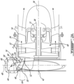
- Fig. 2A presents a sectioned, enlarged view of an example gas turbine intake 16 coupled to a gas turbine 14.
- the gas turbine 14 has a casing 32 defining a radially outer limit of an annular gas path 34 extending along and around a central axis 36, and a rotor 15 having a shaft 38 concentric to the central axis 36.
- the rotor 15 has a plurality of blades 40, and more specifically in this embodiment an axial sequence of two sets of blades.
- the blades 40 of each set are circumferentially interspaced from one another around the central axis 36, and the two sets are axially separated from one another by a set of vanes.
- the blades 40 protrude radially from the shaft 38 across the annular gas path 34.
- the blades 40 rotate in a plane or in a conical virtual surface, and the gas travels across the blades 40 generally perpendicular to the orientation of the length of the blades 40.
- the vanes are made integral to the casing 32 and are thus non-rotary by contrast with the blades 40.
- the radially internal limit of the annular gas path 34 is defined in part by a hub of the vanes, and the vanes protrude radially internally from the outer portion of the casing 32 to the hub.
- Alternate embodiments can have additional sets of blades, additional sets of vanes, or both additional sets of vanes and blades.
- alternate embodiments of a gas turbine can have blades forming a radial to axial transition. While the annular gas path 34 can be said to extend generally axially along the gas turbine 14, it will be understood that in some embodiments, the gas path 34 can extend obliquely or in a curved manner, such as having both conical and cylindrical portions for instance. In some embodiments, it can be preferred to have a set of vanes immediately upstream the first (or only) set of blades, for controlling the swirl in the flow, and/or controlling the angle of attack of the blades relative to the incoming flow of air, which may affect efficiency of energy transfer between the fluid and the blades as known to persons having ordinary skill in the art.
- the gas turbine intake 16 has a swirl housing assembly 42 having a first, radially-outer internal portion thereof forming a swirl path 44.
- the swirl path 44 extends circumferentially around the central axis 36, and more specifically continuously around the central axis 36 in this embodiment.
- An inlet 58 can lead tangentially into the swirl path 44.
- the swirl housing assembly 42 has a second, radially-inner internal portion defining an annular elbow 46 between a radial orientation 48 and an axial orientation 50.
- the annular elbow 46 is provided radially inwardly of the swirl path 44, and fluidly connects the swirl path 44 to the annular outlet 52.
- a plurality of vanes 56 can be provided in the annular elbow 46, the plurality of vanes 56 manifolding the swirl path 44 into a plurality of circumferentially interspaced guide paths 54, wherein each guide path 55 can scoop circumferentially circulating gasses from the swirl path 44 and aerodynamically redirect their circumferential velocity to radially inward velocity and to axial velocity.
- the redirection can be done aerodynamically in a manner to limit aerodynamic losses.
- the redirection can be performed in a manner to limit or otherwise control the occurrence of swirl at the annular outlet 52, and to otherwise direct the flow of gasses in a manner to optimize efficiency of the turbine 14.
- the gas turbine intake 16, and in particular the swirl path 44, extend generally circumferentially, i.e. in a radially-extending plane 48.
- the annular outlet 52 of the gas turbine intake leads directly to the annular gas path 34 of the gas turbine 14, i.e. not via a combustor or compressor.
- Figs 3A to 3C present an example embodiment of a swirl housing assembly 42 in greater detail.
- the swirl housing assembly 42 is made of two portions which can be separated from one another along a joint which extends here in a radial plane.
- the two portions can be referred to as a proximal portion 96 and as a distal portion 98, respectively.
- the proximal portion 96 has an internal recess forming a first portion of the swirl path 44, and more specifically here a first half of the swirl path cross-section area.
- the distal portion 98 has an internal recess forming a second portion of the swirl path 44, and more specifically here a second half of the swirl path cross-section area.
- the proximal portion 96 is fastened to the distal portion 98 at the joint via a plurality of fasteners.
- the fasteners are bolts which extend across corresponding flanges of the distal portion 98 and of the proximal portion 96 and the joint can be referred to as a bolted flange arrangement.
- a gasket 100 is sandwiched between the proximal portion 96 and the distal portion 98. The gasket 100 can be held in the sandwiched configuration by the fasteners.
- the gasket 100 is planar and extends in a radial plane, but it will be understood that in alternate embodiments the gasket can have a more complex shape and/or extend obliquely for instance.
- the swirl housing assembly 42 can include a plurality of vanes 56 located internally to the swirl housing assembly, e.g. adjacent the swirl path 44, and interspaced from one another around the central axis 36.
- the proximal portion 96 is unfastenable from the distal portion 98 by removing the fasteners, and can then be separated from the distal portion 98 to provide a better access to the inside, e.g. a configuration such as shown in Fig. 3B .
- a posteriori this can be useful, in particular, for allowing visual, or non-destructive testing, inspection of the vanes 56 for instance.
- a priori this can be useful for allowing greater design or manufacturing ability to the swirl housing assembly 42, and can be particularly helpful in allowing to manufacture complex vane geometries.
- a separable swirl housing assembly 42 can allow to manufacture the vanes 56 as an exposed portion of one of the two portions, such as by integral casting, soldering or machining, for instance, which can open the door to manufacturing techniques which would not be available if the vanes 56 were to be manufactured as an enclosed, internal component. Subsequently to the manufacturing of the component bearing the vanes 56, the vanes 56 can become enclosed upon fastening of the other portion.
- each vane 56 can be permanently secured to a first one of the proximal portion 96 and of the distal portion 98 and extend, internally to the swirl housing assembly 42, towards the second one of the proximal portion 96 and of the distal portion 98.
- all of the vanes 56 can be secured (e.g. integrally cast) to the proximal portion 96 or to the distal portion 98 and extend towards the other, or some of the vanes 56 can be secured to the proximal portion 96 while the other ones of the vanes 56 can be secured to the distal portion 98.
- the gasket 100 can be helpful in providing an gas-tight seal in the context of a potentially high pressure and high temperature environment of a gas turbine intake 16.
- the gasket 100 can be made of a metal or of a composite material for instance.
- the swirl path 44 extends circumferentially and is confined to the radially extending plane, but it will be noted that other configurations are possible, and the swirl path 44 can be helical in an alternate embodiment for instance.
- the vanes 56 can be absent from an embodiment.
- the joint, and more specifically the gasket 100 is interrupted at the tangential inlet 58 and therefore forms an open shape rather than a closed shape in this embodiment. It can form a closed shape in an alternate embodiment.
- more than one joint can be used, such as a radially outer joint and a radially inner joint.
- Fig. 3B present greater details of an example embodiment having such a plurality of vanes 56.
- the vanes 56 can extend from a leading end 60 configured for scooping circumferentially circulating gasses from the swirl path 44, to a trailing end 62 positioned in the annular outlet 52.
- the vanes 56 have a (generally) flat body which twists, including by being curved radially outwardly between the trailing end 62 and the leading end 60.
- the leading end 60 can protrude radially outwardly from a virtual axial projection 64 of the annular outlet 62.
- the swirl path 44 is located yet further radially outwardly than the leading end 60 and can be said to extend between a radially outer edge, or leading edge, of the leading end 60 and a radially outer wall 66.
- the flat body of the vane 56 can be said to be twisted around a radial axis 70 perpendicular to the central axis 36, as evidenced by the fact that the flat body can be seen to be bent around such an axis 70 between the leading end 60 and the trailing end 62, and that the trailing end 62 terminates axially offset from the leading end 60.
- the twisting around both axes results in a flat body shape which curves relatively smoothly and aerodynamically between a leading edge 76 of the leading end 60 which can be perfectly axial for instance, and a trailing edge 78 of the trailing end 62 which can be perfectly radial for instance, while being circumferentially, radially, and axially offset from the leading edge 76, with the flat body extending smoothly and continuously, in a twisted manner between the trailing edge 78 and the leading edge 76.
- the swirl housing assembly 42 can be said to have a number of generally annularly extending walls.
- the swirl housing assembly 42 can be said to have a radially outer wall 66 which can form a radially outer limit of the swirl path 44, an axially proximal wall 80, and an axially distal wall 82.
- the axially proximal wall 80 can be said to extend annularly and radially between the annular outlet 52 and the radially outer wall 66.
- the axially distal wall 82 can be said to extend annularly and include a curved portion 86 between a radially-extending portion 84 and an axially-extending portion 88, as best seen in Fig. 3A .
- an axially proximal edge 92 of the flat body of each vane 56 can join the axially proximal wall 80, and an axially distal edge 84 of the flat body of each vane 56 can join the axially distal wall 82, with corresponding portions of the axially proximal wall 80 and of the axially distal wall 82, and corresponding vanes, forming corresponding walls of each guide path 54.
- the axially distal edge 94 can be significantly longer in spatial dimension than the axially proximal edge 92, as a result of the twisting of the flat body around the axes.
- Fig. 3C presents a tangentially oriented, close-up view, of the leading end 60 of some of the vanes 56, through the inlet 58, providing an additional point of view of the geometry of the vanes 56 in accordance with an embodiment.
- Fig. 4A and 4B present another example embodiment of a gas turbine intake 116.
- the similarities and differences between the embodiment presented in Figs. 3A to 3D and the embodiment presented in Figs. 4A and 4B will now be detailed.
- the cross-sectional geometry of the gas turbine intake 116 is generally circular rather than generally rectangular (with a rounded edge at the curved portion).
- the swirl path which extends circumferentially around the central axis, terminates at a distal end 196 opposite the inlet 158, and does not fluidly communicate in a recirculating manner between the distal end 196 and the 158.
- the geometry of the guide vanes is adjusted accordingly.
- Fig. 5 presents yet another embodiment of a gas turbine intake 216 which has a swirl housing 242 formed of a proximal portion 296 and a distal portion 298 fastened to one another at a joint.
- the swirl path has a helical geometry and the swirl housing 242 can be entirely devoid of internal vanes.
Landscapes
- Engineering & Computer Science (AREA)
- Chemical & Material Sciences (AREA)
- Combustion & Propulsion (AREA)
- Mechanical Engineering (AREA)
- General Engineering & Computer Science (AREA)
- Physics & Mathematics (AREA)
- Fluid Mechanics (AREA)
- Structures Of Non-Positive Displacement Pumps (AREA)
Abstract
Description
- The application relates generally to gas turbine engines and, more particularly, to a gas turbine intake thereof.
- A gas turbine typically has an annular flow path. The annular flow path may extend axially across one or more alternating sets of stator vanes and rotary blades. In some gas turbine engines, the gas path extends annularly and in sequence across one or more compressor stages and a combustor upstream of one or more turbine stages, and the gas turbine in the form of the one or more turbine stages may readily receive an annular flow of hot gasses from the combustor. In some other embodiments, the source of hot exhaust gasses may not be readily available in an annular configuration, and a challenge can exist in transitioning the hot exhaust gas flow from its source configuration to an annular configuration. Such challenges can be amplified when taking additional factors into consideration such as limiting aerodynamic losses, limiting weight, limiting manufacturing costs, maintenance and inspection, etc. There always remains room for improvement.
- In one aspect, there is provided an aircraft engine comprising : an exhaust conduit; at least one combustion engine having an exhaust gas outlet fluidly connected to the exhaust conduit; at least one gas turbine having a casing defining a radially outer limit of an annular gas path extending along and around a central axis, and at least one rotor having a shaft concentric to the central axis, a plurality of blades circumferentially interspaced from one another around the central axis and protruding from the shaft across the annular gas path; and a swirl housing assembly defining an intake to the gas turbine, the swirl housing assembly having a tangential inlet fluidly connecting the exhaust conduit, an annular outlet fluidly connecting the annular gas path, a swirl path extending around the central axis and between the tangential inlet and the annular outlet, the swirl housing assembly having a proximal portion defining a first portion of the swirl path, a distal portion defining a second portion of the swirl path, the proximal portion fastened to the distal portion via a plurality of fasteners, a gasket sandwiched between the proximal portion and the distal portion by the plurality of fasteners, the gasket extending in a radial plane relative the central axis, the proximal portion unfastenable from and separable from the distal portion to provide access to the swirl path.
- In another aspect, there is provided a gas turbine intake comprising a swirl housing assembly having a tangential inlet fluidly connecting an exhaust conduit, an annular outlet defined around a central axis and fluidly connecting a turbine gas path, a swirl path extending around the central axis and between the tangential inlet and the annular outlet, the swirl housing assembly having a proximal portion defining a first portion of the swirl path, a distal portion defining a second portion of the swirl path, vanes located in the swirl housing assembly, the vanes circumferentially interspaced from one another relative the central axis and extending between the proximal portion and the distal portion, the proximal portion fastened to the distal portion via a plurality of fasteners, a gasket sandwiched between the proximal portion and the distal portion by the plurality of fasteners, the gasket extending in a radial plane relative the central axis, the proximal portion unfastenable from and separable from the distal portion to provide access to the vanes.
- In a further aspect, there is provided a method of inspecting a gas turbine intake having a swirl housing assembly, the method comprising : unfastening a proximal portion of the swirl housing assembly from a distal portion of the swirl housing assembly; separating the proximal portion of the swirl housing assembly from the distal portion of the swirl housing assembly; and inspecting a plurality of vanes of the swirl housing assembly via an access stemming from said separating.
- Reference is now made to the accompanying figures in which:
-
Fig. 1 is a schematic cross-sectional view of a gas turbine engine; -
Fig. 2A is a cross-sectional view, enlarged, of a portion of the gas turbine engine ofFig. 1 ; -
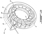
Fig. 2B is a schematic oblique view of a gas turbine intake taken from a proximal side; -
Fig. 3A-3C are a collection of views of a gas turbine intake in accordance with a first embodiment, including an exploded view from a distal side, an oblique view of a distal portion thereof from a proximal side, and a tangential view of the distal portion; -
Fig. 4A is an oblique view of a gas turbine intake in accordance with a second embodiment; -
Fig. 4B is a front elevation view of a proximal portion the gas turbine intake ofFig. 4A ; and -
Fig. 5 is a side elevation view of a gas turbine intake in accordance with a third embodiment. -
Fig. 1 illustrates an aircraft engine 10 of a type preferably provided for use in subsonic flight, generally comprising acombustion engine 12 in which compressed air is mixed with fuel and ignited delivering power and exhaust gasses. The exhaust gasses are collected from thecombustion engine 12 and directed to agas turbine 14. Thegas turbine 14 can convert energy in the form of heat, pressure and/or velocity of the exhaust gasses into angular velocity of arotor 15, and therotor 15 can be used to direct power to one or more other device, such as acompressor 18, a propulsor 20 (e.g. propeller, fan), and/or an electric machine acting as a generator. The transfer of power can be direct, or via a clutch and/or a gearbox. - In the illustrated embodiment, the
combustion engine 12 can have one or more combustion engine units such as piston engine units, and/or Wankel engine units for instance. The exhaust gasses can be collected from one or more exhaust gas outlet of thecombustion engine 12 via anexhaust conduit 22 such as an exhaust pipe, optionally via anexhaust manifold 24 which connects an exhaust pipe to individual engine units. Theexhaust conduit 22 can be straight, continuously curved, or made of straight sections interconnected via one or more elbows, to name some examples. Theexhaust conduit 22 can provide a linear flow of exhaust gasses, whereas thegas turbine 14 can be configured for receiving an annular stream of exhaust gasses. Agas turbine intake 16 can be provided for connecting theexhaust conduit 22 to thegas turbine 14. The gas turbine intake 26 can be configured for receiving the linear flow of exhaust gasses from theexhaust conduit 22, distributing it circumferentially, re-orienting its velocity from a circumferential to an axial orientation, and feeding it as an axially-oriented annular stream to thegas turbine 14, as will be seen more clearly inFig. 2 . - In this embodiment, a
compressor 18 is provided. Thecompressor 18 can be a centrifugal compressor for instance, and be used to boost the pressure of air from the environment in order to feed higher pressure air to the intake of thecombustion engine 12. More specifically, compressed air can be collected from thecompressor 18 by a compressed air pipe, such as via ahelical scroll 28 for instance, and fed to thecombustion engine 12, optionally via anintake manifold 30. Thecompressor 18 can be powered by thegas turbine 14, by thecombustion engine 12, and/or by an auxiliary electric engine, to name some examples. Thecompressor 18 is optional. -
Fig. 2A presents a sectioned, enlarged view of an examplegas turbine intake 16 coupled to agas turbine 14. In this example, thegas turbine 14 has acasing 32 defining a radially outer limit of anannular gas path 34 extending along and around acentral axis 36, and arotor 15 having ashaft 38 concentric to thecentral axis 36. Therotor 15 has a plurality ofblades 40, and more specifically in this embodiment an axial sequence of two sets of blades. Theblades 40 of each set are circumferentially interspaced from one another around thecentral axis 36, and the two sets are axially separated from one another by a set of vanes. Theblades 40 protrude radially from theshaft 38 across theannular gas path 34. Theblades 40 rotate in a plane or in a conical virtual surface, and the gas travels across theblades 40 generally perpendicular to the orientation of the length of theblades 40. The vanes are made integral to thecasing 32 and are thus non-rotary by contrast with theblades 40. In this example, the radially internal limit of theannular gas path 34 is defined in part by a hub of the vanes, and the vanes protrude radially internally from the outer portion of thecasing 32 to the hub. Alternate embodiments can have additional sets of blades, additional sets of vanes, or both additional sets of vanes and blades. Moreover, alternate embodiments of a gas turbine can have blades forming a radial to axial transition. While theannular gas path 34 can be said to extend generally axially along thegas turbine 14, it will be understood that in some embodiments, thegas path 34 can extend obliquely or in a curved manner, such as having both conical and cylindrical portions for instance. In some embodiments, it can be preferred to have a set of vanes immediately upstream the first (or only) set of blades, for controlling the swirl in the flow, and/or controlling the angle of attack of the blades relative to the incoming flow of air, which may affect efficiency of energy transfer between the fluid and the blades as known to persons having ordinary skill in the art. - As seen in
Figs. 2A and2B , in this embodiment, thegas turbine intake 16 has aswirl housing assembly 42 having a first, radially-outer internal portion thereof forming aswirl path 44. Theswirl path 44 extends circumferentially around thecentral axis 36, and more specifically continuously around thecentral axis 36 in this embodiment. Aninlet 58 can lead tangentially into theswirl path 44. Theswirl housing assembly 42 has a second, radially-inner internal portion defining anannular elbow 46 between aradial orientation 48 and anaxial orientation 50. Theannular elbow 46 is provided radially inwardly of theswirl path 44, and fluidly connects theswirl path 44 to theannular outlet 52. As will be explained below, a plurality ofvanes 56 can be provided in theannular elbow 46, the plurality ofvanes 56 manifolding theswirl path 44 into a plurality of circumferentially interspacedguide paths 54, wherein each guide path 55 can scoop circumferentially circulating gasses from theswirl path 44 and aerodynamically redirect their circumferential velocity to radially inward velocity and to axial velocity. The redirection can be done aerodynamically in a manner to limit aerodynamic losses. The redirection can be performed in a manner to limit or otherwise control the occurrence of swirl at theannular outlet 52, and to otherwise direct the flow of gasses in a manner to optimize efficiency of theturbine 14. - The
gas turbine intake 16, and in particular theswirl path 44, extend generally circumferentially, i.e. in a radially-extendingplane 48. Theannular outlet 52 of the gas turbine intake leads directly to theannular gas path 34 of thegas turbine 14, i.e. not via a combustor or compressor. -
Figs 3A to 3C present an example embodiment of aswirl housing assembly 42 in greater detail. In this example, theswirl housing assembly 42 is made of two portions which can be separated from one another along a joint which extends here in a radial plane. The two portions can be referred to as aproximal portion 96 and as adistal portion 98, respectively. Theproximal portion 96 has an internal recess forming a first portion of theswirl path 44, and more specifically here a first half of the swirl path cross-section area. Thedistal portion 98 has an internal recess forming a second portion of theswirl path 44, and more specifically here a second half of the swirl path cross-section area. Theproximal portion 96 is fastened to thedistal portion 98 at the joint via a plurality of fasteners. In this example, the fasteners are bolts which extend across corresponding flanges of thedistal portion 98 and of theproximal portion 96 and the joint can be referred to as a bolted flange arrangement. In this embodiment, agasket 100 is sandwiched between theproximal portion 96 and thedistal portion 98. Thegasket 100 can be held in the sandwiched configuration by the fasteners. When theproximal portion 96 is secured to thedistal portion 98, theswirl path 44 extends in an uninterrupted manner, in the axial orientation, between theproximal portion 96 and thedistal portion 98. In other words, it is open between theproximal portion 96 and thedistal portion 98. In this embodiment, thegasket 100 is planar and extends in a radial plane, but it will be understood that in alternate embodiments the gasket can have a more complex shape and/or extend obliquely for instance. - As best seen in
Fig. 3B , theswirl housing assembly 42 can include a plurality ofvanes 56 located internally to the swirl housing assembly, e.g. adjacent theswirl path 44, and interspaced from one another around thecentral axis 36. - The
proximal portion 96 is unfastenable from thedistal portion 98 by removing the fasteners, and can then be separated from thedistal portion 98 to provide a better access to the inside, e.g. a configuration such as shown inFig. 3B . A posteriori, this can be useful, in particular, for allowing visual, or non-destructive testing, inspection of thevanes 56 for instance. A priori, this can be useful for allowing greater design or manufacturing ability to theswirl housing assembly 42, and can be particularly helpful in allowing to manufacture complex vane geometries. Indeed, instead of having to manufacture thevanes 56 internally to the swirl housing, a separableswirl housing assembly 42 can allow to manufacture thevanes 56 as an exposed portion of one of the two portions, such as by integral casting, soldering or machining, for instance, which can open the door to manufacturing techniques which would not be available if thevanes 56 were to be manufactured as an enclosed, internal component. Subsequently to the manufacturing of the component bearing thevanes 56, thevanes 56 can become enclosed upon fastening of the other portion. - Accordingly, each
vane 56 can be permanently secured to a first one of theproximal portion 96 and of thedistal portion 98 and extend, internally to theswirl housing assembly 42, towards the second one of theproximal portion 96 and of thedistal portion 98. In other words, all of thevanes 56 can be secured (e.g. integrally cast) to theproximal portion 96 or to thedistal portion 98 and extend towards the other, or some of thevanes 56 can be secured to theproximal portion 96 while the other ones of thevanes 56 can be secured to thedistal portion 98. Thegasket 100 can be helpful in providing an gas-tight seal in the context of a potentially high pressure and high temperature environment of agas turbine intake 16. Thegasket 100 can be made of a metal or of a composite material for instance. - In this embodiment, the
swirl path 44 extends circumferentially and is confined to the radially extending plane, but it will be noted that other configurations are possible, and theswirl path 44 can be helical in an alternate embodiment for instance. In some cases, thevanes 56 can be absent from an embodiment. It will be also noted in this embodiment that the joint, and more specifically thegasket 100, is interrupted at thetangential inlet 58 and therefore forms an open shape rather than a closed shape in this embodiment. It can form a closed shape in an alternate embodiment. Moreover, more than one joint can be used, such as a radially outer joint and a radially inner joint. -
Fig. 3B present greater details of an example embodiment having such a plurality ofvanes 56. In this specific embodiment, thevanes 56 can extend from a leadingend 60 configured for scooping circumferentially circulating gasses from theswirl path 44, to a trailingend 62 positioned in theannular outlet 52. Thevanes 56 have a (generally) flat body which twists, including by being curved radially outwardly between the trailingend 62 and theleading end 60. As shown inFig. 2A , the leadingend 60 can protrude radially outwardly from a virtualaxial projection 64 of theannular outlet 62. Theswirl path 44 is located yet further radially outwardly than the leadingend 60 and can be said to extend between a radially outer edge, or leading edge, of theleading end 60 and a radiallyouter wall 66. - The circumferential distribution of the
vanes 56 can be seen more clearly, as well as the configuration where they are circumferentially interspaced from one another relative thecentral axis 36. Eachvane 56 has a twisted and flat body which can be said to have a length extending between the trailingend 62 and theleading end 60. The leadingend 60 is oriented mainly circumferentially and axially at theswirl path 44. More specifically, in this embodiment, the leadingend 60 slopes radially inwardly from the tangential/circumferential orientation, for scooping gasses from theswirl path 44 and directing them radially inwardly towards theannular outlet 52. The trailingend 62 is oriented mainly axially and radially at theannular outlet 52. The flat body of thevane 56 is twisted along its length. More specifically, the flat body of thevane 56 can be said to be twisted around two axes. Firstly, as seen in the figure, the flat body of the vane can be said to be twisted around the central axis, such as more specifically around anaxial axis 68 which is parallel to thecentral axis 36, as evidenced by the fact that the flat body can be seen to be bent around such anaxis 68 between theleading end 60 and the trailingend 62, and that the trailingend 62 terminates radially inwardly relative theleading end 60. Secondly, as seen in the figure, the flat body of thevane 56 can be said to be twisted around aradial axis 70 perpendicular to thecentral axis 36, as evidenced by the fact that the flat body can be seen to be bent around such anaxis 70 between theleading end 60 and the trailingend 62, and that the trailingend 62 terminates axially offset from the leadingend 60. The twisting around both axes results in a flat body shape which curves relatively smoothly and aerodynamically between aleading edge 76 of theleading end 60 which can be perfectly axial for instance, and a trailingedge 78 of the trailingend 62 which can be perfectly radial for instance, while being circumferentially, radially, and axially offset from the leadingedge 76, with the flat body extending smoothly and continuously, in a twisted manner between the trailingedge 78 and the leadingedge 76. - The
swirl housing assembly 42 can be said to have a number of generally annularly extending walls. For instance, theswirl housing assembly 42 can be said to have a radiallyouter wall 66 which can form a radially outer limit of theswirl path 44, an axiallyproximal wall 80, and an axiallydistal wall 82. The axiallyproximal wall 80 can be said to extend annularly and radially between theannular outlet 52 and the radiallyouter wall 66. The axiallydistal wall 82 can be said to extend annularly and include acurved portion 86 between a radially-extendingportion 84 and an axially-extendingportion 88, as best seen inFig. 3A . More specifically, the radially-extendingportion 84 can connect the radiallyouter wall 66, whereas the axially-extendingportion 88 can have a proximal end forming a radially inner edge of theannular outlet 52, the radially outer edge of theannular outlet 52 being formed by a radially inner end of the axiallyproximal wall 80. Thecurved portion 86 can be reminiscent of the geometrical shape of a lower, radially-inner, quarter of a torus for example, and can be said to be a toroidally curved portion. The shape of the toroidally curved portion can be for instance a surface of revolution shape resulting from rotating a roughly 90° arc shape around a central axis. - The
twisted guide paths 54 can be said to be defined as each extending circumferentially between two adjacent ones of thevanes 56, and between the axiallydistal wall 82 and the axiallyproximal wall 80. Thetwisted guide paths 54 can twist first around anaxial axis 68 and then around a radial axis 70 (from the leadingend 60 to the trailing end 62). In particular, thecurved portion 86 of the axiallydistal wall 82 can provide for an aerodynamically smooth transition between the radial velocity orientation and the axial velocity orientation. More specifically, an axiallyproximal edge 92 of the flat body of eachvane 56 can join the axiallyproximal wall 80, and an axiallydistal edge 84 of the flat body of eachvane 56 can join the axiallydistal wall 82, with corresponding portions of the axiallyproximal wall 80 and of the axiallydistal wall 82, and corresponding vanes, forming corresponding walls of eachguide path 54. The axiallydistal edge 94 can be significantly longer in spatial dimension than the axiallyproximal edge 92, as a result of the twisting of the flat body around the axes. It will be noted in this embodiment in particular that the axiallydistal edge 94 of the vane body can continuously follow thecurved portion 86 of the axiallydistal wall 82 of theswirl housing assembly 42. In this embodiment, the axiallydistal edge 94 does so by first extending generally circumferentially, with some degree of radially inward slope, and then gradually curving out axially inwardly, until reaching a generally axial orientation at the trailingend 62 where some degree of slope relative to an axial/tangential plane can be provided in a manner to optimize the orientation of the flow relative thegas turbine 14. A similar configuration can occur at the axiallyproximal edge 92, and a radially inner end of the axiallyproximal wall 80 can be similarly curved, though it can be less pronounced as a result of the fact that the radius of curvature can be significantly smaller at the axiallyproximal wall 80 than at the axiallydistal wall 82, given the general radial to axial transition geometry. -
Fig. 3C presents a tangentially oriented, close-up view, of theleading end 60 of some of thevanes 56, through theinlet 58, providing an additional point of view of the geometry of thevanes 56 in accordance with an embodiment. -
Fig. 4A and 4B present another example embodiment of agas turbine intake 116. The similarities and differences between the embodiment presented inFigs. 3A to 3D and the embodiment presented inFigs. 4A and 4B will now be detailed. - The embodiment presented in
Figs. 4A and 4B also presents agas turbine intake 116 which has aswirl housing assembly 142 formed of aproximal portion 196 and adistal portion 198 fastened to one another at a joint. The swirl housing assembly 148 having aninlet 158 for fluidly connecting an exhaust conduit, anannular outlet 152 defined around a central axis for fluidly connecting a turbine gas path, and a swirl path extending circumferentially around the central axis from the tangential inlet. Thegas turbine intake 116 also has a plurality ofvanes 156 located in theswirl housing assembly 142, thevanes 156 circumferentially interspaced from one another relative the central axis. Thevanes 156 each have a twisted and flat body, having a length extending from a leading end to a trailing end, the leading end being oriented mainly circumferentially and axially at the swirl path, the trailing end being oriented mainly axially and radially at theannular outlet 152. The twisted and flat body twists between the leading end and the trailing end around the central axis, and around a radial axis perpendicular to the central axis. - However, contrary to the
gas turbine intake 16 presented inFig. 3A -3D, the cross-sectional geometry of thegas turbine intake 116 is generally circular rather than generally rectangular (with a rounded edge at the curved portion). Moreover, the swirl path, which extends circumferentially around the central axis, terminates at adistal end 196 opposite theinlet 158, and does not fluidly communicate in a recirculating manner between thedistal end 196 and the 158. The geometry of the guide vanes is adjusted accordingly. -
Fig. 5 presents yet another embodiment of agas turbine intake 216 which has aswirl housing 242 formed of aproximal portion 296 and adistal portion 298 fastened to one another at a joint. In this embodiment, the swirl path has a helical geometry and theswirl housing 242 can be entirely devoid of internal vanes. - The embodiments described in this document provide non-limiting examples of possible implementations of the present technology. Upon review of the present disclosure, a person of ordinary skill in the art will recognize that changes may be made to the embodiments described herein without departing from the scope of the present technology. For example, other fasteners than bolts can be used, such as rivets for instance. Moreover, in the illustrated embodiment, each one of the portions forms roughly one half of the swirl path, but it will be noted that other proportions can be preferred in alternate embodiments, such as 1/3 being formed by the proximal side and 2/3 being formed by the distal side for instance. Yet further modifications could be implemented by a person of ordinary skill in the art in view of the present disclosure, which modifications would be within the scope of the present technology.
Claims (14)
- An aircraft engine (10) comprising :an exhaust conduit (22);at least one combustion engine (12) having an exhaust gas outlet fluidly connected to the exhaust conduit (22);at least one gas turbine (14) having a casing (32) defining a radially outer limit of an annular gas path (34) extending along and around a central axis (36), and at least one rotor (15) having a shaft (38) concentric to the central axis (36), a plurality of blades (40) circumferentially interspaced from one another around the central axis (36) and protruding from the shaft (38) across the annular gas path (34); anda swirl housing assembly (42) defining an intake (26) to the gas turbine (14), the swirl housing assembly (42) having a tangential inlet (58) fluidly connecting the exhaust conduit (22), an annular outlet (52) fluidly connecting the annular gas path (34), a swirl path (44) extending around the central axis (36) and between the tangential inlet (58) and the annular outlet (52), the swirl housing assembly (42) having a proximal portion (96) defining a first portion of the swirl path (44), a distal portion (98) defining a second portion of the swirl path (44), the proximal portion (96) fastened to the distal portion (98) via a plurality of fasteners, a gasket (100) sandwiched between the proximal portion (96) and the distal portion (98) by the plurality of fasteners, the gasket (100) extending in a radial plane relative the central axis (36), the proximal portion (96) unfastenable from and separable from the distal portion (98) to provide access to the swirl path (44).
- The aircraft engine (10) of claim 1 wherein the swirl housing assembly (42) further comprises vanes (56) interspaced from one another around the central axis (36).
- A gas turbine intake (26) comprising a swirl housing assembly (42) having a tangential inlet (58) fluidly connecting an exhaust conduit (22), an annular outlet (52) defined around a central axis (36) and fluidly connecting a turbine gas path (34), a swirl path (44) extending around the central axis (36) and between the tangential inlet (58) and the annular outlet (52), the swirl housing assembly (42) having a proximal portion (96) defining a first portion of the swirl path (44), a distal portion (98) defining a second portion of the swirl path (44), vanes (56) located in the swirl housing assembly (42), the vanes (56) circumferentially interspaced from one another relative the central axis (36) and extending between the proximal portion (96) and the distal portion (98), the proximal portion (96) fastened to the distal portion (98) via a plurality of fasteners, a gasket (100) sandwiched between the proximal portion (96) and the distal portion (98) by the plurality of fasteners, the gasket (100) extending in a radial plane relative the central axis (36), the proximal portion (96) unfastenable from and separable from the distal portion (98) to provide access to the vanes (56).
- The aircraft engine (10) of claim 2 or the gas turbine intake (26) of claim 3 wherein each vane (56) is secured to a first one of the proximal portion (96) and of the distal portion (98) and extends towards a second one of the proximal portion (96) and of the distal portion (98).
- The aircraft engine (10) of claim 2 or 4 or the gas turbine intake (26) of claim 3 or 4 wherein each vane (56) is integrally cast to a corresponding one of the proximal portion (96) and of the distal portion (98).
- The gas turbine intake (26) or the aircraft engine (10) of any preceding claim wherein the fasteners are bolts, the bolts being engaged with bores formed in both a flange of the distal portion (98) and a flange of the proximal portion (96).
- The gas turbine intake (26) or the aircraft engine (10) of any preceding claim wherein the gasket (100) is made of one of a metal and a composite material.
- The gas turbine intake (26) or the aircraft engine (10) of any preceding claim wherein the proximal portion (196) is a proximal half defining a first half of the swirl path (44) and the distal portion (98) is a distal half defining a second half of the swirl path (44).
- The gas turbine intake (26) or the aircraft engine (10) of any preceding claim wherein the swirl path (44) extends circumferentially and is confined to a radially extending plane.
- A method of inspecting a gas turbine intake (26) having a swirl housing assembly (42), the method comprising :unfastening a proximal portion (96) of the swirl housing assembly (42) from a distal portion (98) of the swirl housing assembly (42);separating the proximal portion (96) of the swirl housing assembly (42) from the distal portion (98) of the swirl housing assembly (42); andinspecting a plurality of vanes (56) of the swirl housing assembly (42) via an access stemming from said separating.
- The method of claim 10 wherein said inspecting includes performing non-destructive testing to the plurality of vanes (156).
- The method of claim 10 or 11 further comprising re-positioning the proximal portion (96) against the distal portion (98) and fastening the proximal portion (96) to the distal portion (98).
- The method of claim 12 wherein said re-positioning includes positioning a seal between the proximal portion (96) and the distal portion (98) prior to said fastening.
- The method of any of claims 10 to 13 further comprising removing and replacing a seal from between the proximal portion (96) and the distal portion (98).
Applications Claiming Priority (1)
| Application Number | Priority Date | Filing Date | Title |
|---|---|---|---|
| US17/858,289 US11821361B1 (en) | 2022-07-06 | 2022-07-06 | Gas turbine intake for aircraft engine and method of inspection thereof |
Publications (1)
| Publication Number | Publication Date |
|---|---|
| EP4400695A1 true EP4400695A1 (en) | 2024-07-17 |
Family
ID=87158474
Family Applications (1)
| Application Number | Title | Priority Date | Filing Date |
|---|---|---|---|
| EP23184005.9A Pending EP4400695A1 (en) | 2022-07-06 | 2023-07-06 | Gas turbine intake for aircraft engine and method of inspection thereof |
Country Status (3)
| Country | Link |
|---|---|
| US (1) | US11821361B1 (en) |
| EP (1) | EP4400695A1 (en) |
| CA (1) | CA3203404A1 (en) |
Families Citing this family (1)
| Publication number | Priority date | Publication date | Assignee | Title |
|---|---|---|---|---|
| US12264595B2 (en) * | 2023-06-29 | 2025-04-01 | Pratt & Whitney Canada Corp. | Turbine support case having axial spokes |
Citations (3)
| Publication number | Priority date | Publication date | Assignee | Title |
|---|---|---|---|---|
| GB688111A (en) * | 1945-05-23 | 1953-02-25 | Miles Lowell Edwards | Improvements in or relating to liquid and gas separating devices |
| US3396906A (en) * | 1968-02-06 | 1968-08-13 | Trane Co | Pump housing seal arrangement |
| CN107725195A (en) * | 2017-11-23 | 2018-02-23 | 上海泛智能源装备有限公司 | A kind of air inlet volute and gas turbine |
Family Cites Families (15)
| Publication number | Priority date | Publication date | Assignee | Title |
|---|---|---|---|---|
| US2385366A (en) * | 1938-04-19 | 1945-09-25 | Jarvis C Marble | Power plant for aircraft |
| GB571022A (en) | 1942-06-11 | 1945-08-02 | Chicago Metal Hose Corp | Improvements relating to flexible pipe connections or conduits |
| US2801043A (en) | 1954-08-24 | 1957-07-30 | Thompson Prod Inc | Turbine supercharger |
| US4996839A (en) * | 1987-02-24 | 1991-03-05 | Teledyne Industries, Inc. | Turbocharged compound cycle ducted fan engine system |
| US5145215A (en) | 1991-04-26 | 1992-09-08 | Senior Engineering Investments, B.V. | Flexible coupler apparatus |
| DE19936170A1 (en) | 1999-07-31 | 2001-02-01 | Rolls Royce Deutschland | Cooling air pipe for aircraft gas turbine engine consists of double-walled three-part pipe with inner tube for cooling air flow |
| US7074009B2 (en) | 2000-06-07 | 2006-07-11 | Borgwarner, Inc. | Casing assembly for the turbine of an exhaust turbochanger |
| US6783321B2 (en) | 2002-11-06 | 2004-08-31 | General Electric Company | Diffusing coupling cover for axially joined turbines |
| US7147433B2 (en) * | 2003-11-19 | 2006-12-12 | Honeywell International, Inc. | Profiled blades for turbocharger turbines, compressors, and the like |
| JP5433560B2 (en) | 2010-12-27 | 2014-03-05 | 三菱重工業株式会社 | Turbine scroll part structure |
| JP5984446B2 (en) * | 2012-03-23 | 2016-09-06 | 三菱重工業株式会社 | Turbine housing assembly and method of manufacturing turbine housing assembly |
| JP5975698B2 (en) * | 2012-03-30 | 2016-08-23 | 大豊工業株式会社 | Turbocharger |
| JP5880463B2 (en) * | 2013-01-29 | 2016-03-09 | 株式会社豊田自動織機 | Turbocharger |
| US10030581B2 (en) | 2016-02-24 | 2018-07-24 | Pratt & Whitney Canada Corp. | Air intake with scroll portion and strutted portion for gas turbine engine |
| GB2552686B (en) | 2016-08-03 | 2020-04-29 | Rolls Royce Plc | Gimbal expansion joint |
-
2022
- 2022-07-06 US US17/858,289 patent/US11821361B1/en active Active
-
2023
- 2023-06-14 CA CA3203404A patent/CA3203404A1/en active Pending
- 2023-07-06 EP EP23184005.9A patent/EP4400695A1/en active Pending
Patent Citations (3)
| Publication number | Priority date | Publication date | Assignee | Title |
|---|---|---|---|---|
| GB688111A (en) * | 1945-05-23 | 1953-02-25 | Miles Lowell Edwards | Improvements in or relating to liquid and gas separating devices |
| US3396906A (en) * | 1968-02-06 | 1968-08-13 | Trane Co | Pump housing seal arrangement |
| CN107725195A (en) * | 2017-11-23 | 2018-02-23 | 上海泛智能源装备有限公司 | A kind of air inlet volute and gas turbine |
Also Published As
| Publication number | Publication date |
|---|---|
| US11821361B1 (en) | 2023-11-21 |
| CA3203404A1 (en) | 2024-01-06 |
Similar Documents
| Publication | Publication Date | Title |
|---|---|---|
| EP4296472B1 (en) | Aircraft engine, gas turbine intake therefore, and method of guiding exhaust gasses | |
| EP2762682B1 (en) | Axial turbine with meridionally divided turbine housing | |
| EP4488490A1 (en) | Turbine support case having axial spokes | |
| US9429162B2 (en) | Axial turbine with sector-divided turbine housing | |
| EP2875222B1 (en) | Gas turbine engine outer case with contoured bleed boss | |
| US20170234139A1 (en) | Impingement holes for a turbine engine component | |
| US11572798B2 (en) | Variable guide vane for gas turbine engine | |
| CN107191413A (en) | Dupler connects system | |
| US11988112B2 (en) | Recovered-cycle aircraft turbomachine | |
| US11821361B1 (en) | Gas turbine intake for aircraft engine and method of inspection thereof | |
| US11851202B1 (en) | Aircraft engine, gas turbine intake therefore, and method of guiding exhaust gasses | |
| CN121195107A (en) | Recycled Circulating Aircraft Turbine Engine | |
| EP3567224B1 (en) | Turbocharger having a meridionally divided turbine housing | |
| US20260049618A1 (en) | Recovered-cycle aircraft turbine engine | |
| EP4311943B1 (en) | Diffuser and associated compressor section of aircraft engine | |
| CN107429608A (en) | Turbine and turbocharger | |
| EP4741635A1 (en) | Aircraft engine including diffuser secured to a bearing housing | |
| EP4733552A1 (en) | Aircraft engine having a scroll case and a turbine support case secured together | |
| EP4726179A1 (en) | Turbine support case with axial spokes and brackets | |
| EP4726180A1 (en) | Turbine support case supported by stopping ribs | |
| CN120426132A (en) | Compressor assembly for a gas turbine engine with multi-stage exhaust gas extraction |
Legal Events
| Date | Code | Title | Description |
|---|---|---|---|
| PUAI | Public reference made under article 153(3) epc to a published international application that has entered the european phase |
Free format text: ORIGINAL CODE: 0009012 |
|
| STAA | Information on the status of an ep patent application or granted ep patent |
Free format text: STATUS: THE APPLICATION HAS BEEN PUBLISHED |
|
| AK | Designated contracting states |
Kind code of ref document: A1 Designated state(s): AL AT BE BG CH CY CZ DE DK EE ES FI FR GB GR HR HU IE IS IT LI LT LU LV MC ME MK MT NL NO PL PT RO RS SE SI SK SM TR |
|
| STAA | Information on the status of an ep patent application or granted ep patent |
Free format text: STATUS: REQUEST FOR EXAMINATION WAS MADE |
|
| 17P | Request for examination filed |
Effective date: 20250117 |
|
| GRAP | Despatch of communication of intention to grant a patent |
Free format text: ORIGINAL CODE: EPIDOSNIGR1 |
|
| STAA | Information on the status of an ep patent application or granted ep patent |
Free format text: STATUS: GRANT OF PATENT IS INTENDED |
|
| INTG | Intention to grant announced |
Effective date: 20250627 |
|
| GRAJ | Information related to disapproval of communication of intention to grant by the applicant or resumption of examination proceedings by the epo deleted |
Free format text: ORIGINAL CODE: EPIDOSDIGR1 |
|
| STAA | Information on the status of an ep patent application or granted ep patent |
Free format text: STATUS: REQUEST FOR EXAMINATION WAS MADE |
|
| INTC | Intention to grant announced (deleted) | ||
| GRAP | Despatch of communication of intention to grant a patent |
Free format text: ORIGINAL CODE: EPIDOSNIGR1 |
|
| STAA | Information on the status of an ep patent application or granted ep patent |
Free format text: STATUS: GRANT OF PATENT IS INTENDED |
|
| INTG | Intention to grant announced |
Effective date: 20260306 |