EP4400643A1 - Steaming device comprising a pole assembly and a support base - Google Patents
Steaming device comprising a pole assembly and a support base Download PDFInfo
- Publication number
- EP4400643A1 EP4400643A1 EP23151365.6A EP23151365A EP4400643A1 EP 4400643 A1 EP4400643 A1 EP 4400643A1 EP 23151365 A EP23151365 A EP 23151365A EP 4400643 A1 EP4400643 A1 EP 4400643A1
- Authority
- EP
- European Patent Office
- Prior art keywords
- pole
- support base
- steaming device
- assembly
- pole assembly
- Prior art date
- Legal status (The legal status is an assumption and is not a legal conclusion. Google has not performed a legal analysis and makes no representation as to the accuracy of the status listed.)
- Withdrawn
Links
Images




Classifications
-
- D—TEXTILES; PAPER
- D06—TREATMENT OF TEXTILES OR THE LIKE; LAUNDERING; FLEXIBLE MATERIALS NOT OTHERWISE PROVIDED FOR
- D06F—LAUNDERING, DRYING, IRONING, PRESSING OR FOLDING TEXTILE ARTICLES
- D06F81/00—Ironing boards
-
- D—TEXTILES; PAPER
- D06—TREATMENT OF TEXTILES OR THE LIKE; LAUNDERING; FLEXIBLE MATERIALS NOT OTHERWISE PROVIDED FOR
- D06F—LAUNDERING, DRYING, IRONING, PRESSING OR FOLDING TEXTILE ARTICLES
- D06F81/00—Ironing boards
- D06F81/006—Ironing boards with fabric support or garment rack
-
- D—TEXTILES; PAPER
- D06—TREATMENT OF TEXTILES OR THE LIKE; LAUNDERING; FLEXIBLE MATERIALS NOT OTHERWISE PROVIDED FOR
- D06F—LAUNDERING, DRYING, IRONING, PRESSING OR FOLDING TEXTILE ARTICLES
- D06F81/00—Ironing boards
- D06F81/08—Ironing boards incorporating heating, steaming, or forced ventilation means
Definitions
- the invention relates to a steaming device comprising a pole assembly that is mountable to a support base.
- the invention may be used in the field of garment care.
- Steaming devices are known to be used for ironing or steaming garments to remove creases through the use of heat and moisture from steam.
- One type of steaming device is a so-called "all-in-one" steaming device that comprises a base unit, which base unit houses a water tank.
- a steamer head which can be alternatively referred to as an ironing device or a handheld unit, is connected to the base unit by a flexible hose through which steam and/or water is delivered from the base unit to the steamer head.
- a steam generator is included in the base unit and/or the steamer head.
- the steamer head is provided with a treatment plate, also known as a soleplate, delimiting one or more steam vents through which steam is discharged onto a fabric being treated.
- Steaming devices can include a support base, in other words a stand, to which a pole assembly is mounted.
- the support base assists to minimize the risk of the pole assembly toppling over during use.
- Such steaming devices can also include an ironing board for facilitating steaming and/or ironing of garments.
- Such an ironing board can be supported by the pole assembly mounted to the support base.
- Storing and transporting steaming devices that include such a support base and pole assembly tend to require that the pole assembly is detachably mountable to the support base.
- the capability to supply the steaming device to the user with the pole assembly being detached from the support base can assist to minimize the size of packaging required for the steaming device, and can facilitate transportation of the steaming device.
- the user Prior to use, the user can mount the pole assembly to the support base.
- the nature of the interface between the pole assembly and the support base that enables the pole assembly to be detachably mountable to the support base can result in instability of the mounted pole assembly, and thus instability of an ironing board being supported by the pole assembly and the support base.
- forces due to movement of the steamer head during ironing or steaming can be transmitted down the pole assembly to the support base.
- the effect of gaps at the interface between the pole assembly and the support base on movement of the pole assembly relative to the support base can be amplified by the length of the pole assembly. This, in turn, can cause the pole assembly to be perceived by the user as being wobbly. The user's confidence that the steaming device is safe to use can therefore risk being undermined.
- the steaming device comprises:
- the engagement of the protruding element with the interior surface of the cap can assist to ensure robust and stable mounting of the pole assembly to the support base, whilst still enabling facile detachment of the pole assembly from the support base.
- the cap-protruding element arrangement can assist in terms of easing manufacturing tolerance-related requirements in respect of the pole of the pole assembly. Accordingly, various possibilities concerning the design of the pole can be implemented with no or minimal compromise in terms of robust and stable mounting of the pole assembly to the support base.
- the pole can be made of a metallic material, e.g. aluminium, and/or the pole can have an elongate cross-sectional shape, such as a rectangular, rounded rectangular or elliptical.
- the engagement of the protruding element with the interior surface of the cap can be regarded as at least partly defining an interference fit between the pole assembly and the pole support element.
- the lower portion of the pole terminates at a bottom end of the pole, and the cap has a rim portion that protrudes from the bottom end of the pole.
- the rim portion is receivable in a groove defined in the pole support element, which groove extends around the protruding element, when the protruding element is received in the hollow portion.
- the groove is preferably provided between the protruding element and an outer part of the pole support element that extends to reach, and is attached to, an upper shell and/or a lower shell of the support base.
- a leg defined by the outer part of the pole support element can couple the protruding element to the upper shell and/or the lower shell.
- a first surface and a second surface of the pole support element face each other across the groove, and the rim portion is arranged to contact one or both of the first surface and the second surface when the rim portion is received in the groove.
- the interference fit between the pole assembly and the pole support element can include the rim portion and surface(s) of the pole support element delimiting the groove being pressed against each other.
- the rim portion e.g. an annular rim portion, can be mounted tightly in the groove when the pole assembly is mounted to the support base.
- the protruding element comprises a plurality of crush ribs arranged around the protruding element, with the interior surface of the cap and the crush ribs being pressed against each other when the protruding element is received in the hollow portion.
- the crush ribs interfering with the interior surface of the cap can assist to restrict movement of the pole assembly when the pole assembly is mounted to the support base.
- the crush ribs are distributed around a perimeter of the protruding element.
- This distribution of the crush ribs can assist to minimize gaps at the interface between the pole assembly and the pole support element when the pole assembly is mounted to the support base.
- the upper portion of the support base comprises a mounting boss for supporting the pole, with the hole delimited by the upper portion of the support base extending through the mounting boss.
- the mounting boss can thus assist to increase the length over which the pole assembly is supportable by the support base.
- the steaming device comprises a pole fastening assembly for releasably fastening the pole assembly to the support base.
- Securing the pole at a distance from the bottom end of the pole in this way in addition to the bottom end being secured via the protruding element of the pole support being received in the hollow portion of the cap, can significantly improve the rigidity of the interface between the pole assembly and the support base.
- the pole fastening assembly preferably includes a pushing member coupled to the support base, and a cam lever pivotable between a locking position in which the cam lever exerts a force on the pushing member that causes the pushing member to push against the pole, and a releasing position in which the force is released.
- Such a pole fastening assembly which can be alternatively termed a "cam lock”, can assist to minimize or prevent movement of the pole assembly when the pole assembly is mounted to the support base.
- the force on the pushing member can cause the pole to be squeezed between the pushing member and surface(s) of the upper portion of the support base that delimit(s) the hole.
- the pole assembly When the cam lever is in the releasing position, the pole assembly can be detached from the support base, in particular by causing the protruding element to be removed from the hollow portion of the cap.
- the latter can be achieved by, for instance, pulling the pole with sufficient force away from the support base.
- the pushing member is preferably arranged such that, when the cam lever is positioned to exert the force on the pushing member that causes the pushing member to push against the pole, the pole is squeezed between the pushing member and an inner surface of the mounting boss.
- the cam lock can thus assist to minimize or avoid gap(s) between the pole and the mounting boss, and thereby reduce wobbling of the pole assembly when the pole assembly is mounted to the support base.
- the support base comprises a lower shell and an upper shell attached to the lower shell, with the upper shell comprising the upper portion of the support base that delimits the hole.
- a space is defined between the lower shell and the upper shell, and at least part of the pole support element is arranged within the space.
- the pole support element is attached to the lower shell and/or to the upper shell.
- the pole support element can be attached, e.g. rigidly coupled, to the lower shell and/or to the upper shell in any suitable manner.
- one or more fasteners e.g. screw(s) can be used to attach the pole support element to the lower shell and/or to the upper shell.
- Such fastener(s), e.g. screw(s), can assist to minimize or prevent movement of the pole support element within the support base.
- the lower shell comprises a mounting structure arranged around and adapted to press against the pole support element. This can help to minimize movement of the pole support element in the support base.
- the mounting structure comprises, e.g. is defined by, an annular protrusion provided on the lower shell.
- an annular protrusion preferably extends into an annular cavity provided in the pole support element.
- the pole has a cross-sectional shape selected from the following: rectangular, rounded rectangular, square, rounded square, elliptical, or circular.
- the secure mounting of the pole assembly via the cap-protruding element arrangement can mean that various different possibilities are available in terms of the shape of the pole.
- the cap-protruding element arrangement can assist to suppress wobbling of the pole that is as a consequence of the pole having an elongate cross-sectional shape, such as rectangular, rounded rectangular or elliptical.
- the pole can be made of a metallic material, in other words a metal alloy or a metal.
- the pole is made of aluminium. Such an aluminium pole benefits from being relatively strong but also lightweight.
- the secure mounting of the pole assembly via the cap-protruding element arrangement can assist to mitigate manufacturing tolerances-related issues associated with the pole being made of a metallic material, such as aluminium.
- the cap is made of one or more selected from a plastic material, such as an engineering thermoplastic, and a metallic material, in other words a metal alloy or a metal, e.g. aluminium.
- the cap is made of a moulded plastic material, such as a moulded engineering thermoplastic.
- the cap is made of die cast aluminium.
- the pole assembly is a telescopic pole assembly that comprises the pole and an upper pole, with the upper pole being slidable out of and into an upper end of the pole to enable extension and collapsing of the telescopic pole assembly.
- the steaming device comprises an ironing board, with the ironing board being supportable by the pole assembly and the support base.
- extension and collapsing of the telescopic pole assembly can enable height adjustment of the ironing board.
- the steaming device comprises a base unit comprising a water tank, a steamer head having a treatment plate delimiting at least one steam vent, and a hose cord connecting the base unit to the steamer head.
- the support base is preferably arranged to support the base unit.
- the base unit can be supported by the support base to which the pole assembly is detachably mountable.
- Fig.1 depicts a steaming device 100 according to an example.
- the steaming device 100 comprises a support base 102.
- a pole assembly 108 is detachably mountable to the support base 102.
- the capability to supply the pole assembly 108 detached from the support base 102 can assist to minimize the size of packaging required for transporting the steaming device 100 and can facilitate transportation of the steaming device 100. Being able to detach the pole assembly 108 from the support base 102 can also assist a user wishing to stow the steaming device 100 in a storage area after use.
- an upper portion 104 of the support base 102 delimits a hole 106.
- the pole assembly 108 and the support base 102 are arranged such that the pole assembly 108 extends through the hole 106 and upstands from the support base 102 when the pole assembly 108 is mounted to the support base 102.
- the pole assembly 108 for example specifically the pole 110 included in the pole assembly 108, preferably contacts surface(s) of the upper portion 104 that delimit the hole 106.
- Such contact can assist to reduce wobbling of the pole assembly 108 when the pole assembly 108 is mounted to the support base 102.
- the pole 110 is dimensioned to fit the hole 106 such that the surface(s) delimiting the hole 106 assist(s) to restrict movement of the pole 110 when the pole assembly 108 is mounted to the support base 102.
- the pole 110 is hollow at least at a lower portion of the pole 110, and a cap 114 is received inside the lower portion of the pole 110 when the pole assembly 108 is assembled.
- the cap 114 can assist to ensure robust and stable mounting of the pole assembly 108 to the support base 102, as explained in more detail herein below.
- the steaming device 100 further includes a pole support element 118.
- the pole support element 118 when fixed to the support base 102, assists in mounting the pole assembly 108 to the support base 102.
- the pole 110 can have any suitable shape.
- the pole 110 has a cross-sectional shape selected from the following: rectangular, rounded rectangular, square, rounded square, elliptical, or circular.
- the pole 110 has an elongate cross-sectional shape, such as rectangular, rounded rectangular or elliptical.
- deformation along the sides of the pole 110 can potentially be significant, and can increase the risk of wobbling of the pole 110 when mounted to the support base 102.
- the manner of mounting the pole assembly 108 to the support base 102 can assist to alleviate potential instability issues associated with the cross-sectional shape of the pole 110.
- the pole 110 can be formed of any suitable material.
- the pole 110 is made of a metallic material.
- the pole 110 is made of aluminium. Such an aluminium pole 110 benefits from being relatively strong but also lightweight.
- Difficulties can nonetheless be encountered with such an aluminium pole 110, particularly in ensuring that manufacturing tolerances are consistently accurate.
- a bottom end 112 of the pole 110, at which the lower portion of the pole 110 terminates may not easily fit into a groove 120 defined in the pole support element 118. This can compromise mounting of the pole 110 to the support base 102.
- the manner of mounting the pole assembly 108 to the support base 102 can assist to alleviate such material-related pole 110 instability issues.
- the pole support element 118 comprises a protruding element 122.
- the protruding element 122 upwardly protrudes in the direction of extension of the pole assembly 108 when the pole assembly 108 is mounted to the support base 102.
- an interior surface 124 of the cap 114 delimits a hollow portion 126 of the cap 114, and the protruding element 122 is receivable in the hollow portion 126 and dimensioned so that the protruding element 122 engages the interior surface 124 of the cap 114.
- the engagement of the protruding element 122 with the interior surface 124 of the cap 114 can assist to ensure robust and stable mounting of the pole assembly 108 to the support base 102.
- the cap-protruding element arrangement 114, 122 can assist in terms of easing manufacturing tolerance-related requirements in respect of the pole 110 of the pole assembly 108. Accordingly, various possibilities concerning the design of the pole 110 can be implemented with no or minimal compromise in terms of robust and stable mounting of the pole assembly 108 to the support base 102.
- the pole 110 can be made of a metallic material, e.g. aluminium, and/or the pole 110 can have an elongate cross-sectional shape, such as rectangular, rounded rectangular or elliptical.
- the engagement of the protruding element 122 with the interior surface 124 of the cap 114 can be regarded as at least partly defining an interference fit between the pole assembly 108 and the pole support element 118.
- the interference fit between the pole assembly 108 and the pole support element 118 can include the interior surface 124 of the cap 114 and the protruding element 122 being pressed against each other.
- the protruding element 122 can be removed from the hollow portion 126 of the cap 114, for example by pulling the pole 110 with sufficient force away from the support base 102, e.g. following release of a pole fastening assembly 132 as described herein below.
- the pole 110, together with the cap 114 can be detached from the support base 102.
- the cap 114 can be made of any suitable material.
- the cap 114 is made of one or more selected from a plastic material, such as an engineering thermoplastic, and a metallic material, such as aluminium.
- the cap 114 is made of a moulded plastic material, such as a moulded engineering thermoplastic.
- the cap 114 is made of die cast aluminium.
- the cap 114 includes one or more fastening members 125, such as one or more snap-fit fastening members 125, for securing the cap 114 inside the lower portion of the pole 110.
- the fastening member(s) 125 include resiliently mounted protruding catch(es) that are each receivable in a recess or aperture defined in the lower portion of the pole 110 in order to secure the cap 114 to the lower portion of the pole 110.
- an exterior surface 127 of the cap 114 can contact, and thus frictionally engage with, an inner surface of the lower portion of the pole 110.
- the cap 114 comprises an internal reinforcement member 129.
- the internal reinforcement member 129 can assist to enhance the structural integrity of the cap 114.
- the internal reinforcement member 129 can have any suitable form/shape.
- the internal reinforcement member 129 comprises, e.g. is defined by, a grid mounted within the cap 114.
- the protruding element 122 comprises a plurality of crush ribs 128 arranged around the protruding element 122.
- the interior surface 124 of the cap 114 and the crush ribs 128 are pressed against each other when the protruding element 122 is received in the hollow portion 126.
- the engagement of the protruding element 122 with the interior surface 124 of the cap 114 can include, e.g. be defined by, engagement of the crush ribs 128 of the protruding element 122 with the interior surface 124 of the cap 114.
- the crush ribs 128 interfering with the interior surface 124 of the cap 114 can assist to restrict movement of the pole assembly 108 when the pole assembly 108 is mounted to the support base 102.
- the crush ribs 128 are preferably distributed around a perimeter of the protruding element 122. This distribution of the crush ribs 128 can assist to minimize gaps at the interface between the pole assembly 108 and the pole support element 118 when the pole assembly 108 is mounted to the support base 102.
- the hollow portion 126 preferably has a cross-sectional shape that complements a profile of the protruding element 122.
- the protruding element 122 can fit snuggly inside the hollow portion 126, with concomitant enhancement of stability of mounting of the pole assembly 108 to the support base 102.
- the upper portion 104 of the support base 102 comprises a mounting boss 130 for supporting the pole 110.
- the mounting boss 130 upwardly projects in the direction of extension of the pole assembly 108 from the support base 102 when the pole assembly 108 is mounted to the support base 102, as best shown in Figs.2 , 5A and 5B .
- the hole 106 through which the pole assembly 108 passes when the pole assembly 108 is mounted to the support base 102 extends through the mounting boss 130.
- the mounting boss 130 can thus assist to increase the length over which the pole assembly 108 is supportable by the support base 102.
- the pole assembly 108 for example specifically the pole 110 included in the pole assembly 108, preferably contacts inner surface(s) 138 of the mounting boss 130 that delimit(s) the hole 106.
- An example of this is best shown in Fig.5F .
- the mounting boss 130 assists to increase the length over which the pole assembly 108 contacts the support base 102. This, in turn, can enhance the stability of the pole assembly 108 when the pole assembly 108 is mounted to the support base 102.
- the arrows 131 in Fig.5A point to areas of tight contact between the pole 110 and the inner surface(s) 138 of the mounting boss 130 that delimit(s) the hole 106.
- the steaming device 100 comprises a pole fastening assembly 132 for releasably fastening the pole 110 to the support base 102.
- the pole fastening assembly 132 preferably includes a pushing member 134 coupled to the support base 102, and a cam lever 136 pivotable between a locking position, as shown in Figs.5E and 5F , in which the cam lever 136 exerts a force on the pushing member 134 that causes the pushing member 134 to push against the pole 110, and a releasing position in which the force is released.
- Such a pole fastening assembly 132 which can be alternatively termed a "cam lock”, can assist to minimize or prevent movement of the pole assembly 108 when the pole assembly 108 is mounted to the support base 102.
- the force on the pushing member 134 can cause the pole 110 to be squeezed between the pushing member 134 and surface(s) of the upper portion 104 of the support base 102 that delimit(s) the hole 106.
- the pole assembly 108 can be detached from the support base 102, in particular by causing the protruding element 122 to be removed from the hollow portion 126 of the cap 114, as previously described.
- the pushing member 134 is preferably arranged such that, when the cam lever 136 is positioned to exert the force on the pushing member 134 that causes the pushing member 134 to push against the pole 110, the pole 110 is squeezed between the pushing member 134 and the inner surface(s) 138 of the mounting boss 130.
- the cam lock can thus assist to minimize or avoid gap(s) between the pole 110 and the mounting boss 130, and thereby reduce wobbling of the pole assembly 108 when the pole assembly 108 is mounted to the support base 102.
- the pushing member 134 can be made of any suitable material.
- the pushing member 134 is made of a plastic material, such as an engineering thermoplastic.
- the pushing member 134 When the pushing member 134 is made of a plastic material, it can take the form of a plastic block that is movable by the cam lever 136 against the pole 110.
- a pivot coupling 137 couples the cam lever 136 to the support base 102 and enables pivoting of the cam lever 136 between the locking position and the releasing position.
- the support base 102 comprises a lower shell 140 and an upper shell 142 attached to the lower shell 140, with the upper shell 142 comprising the upper portion 104 of the support base 102 that delimits the hole 106.
- a space is defined between the lower shell 140 and the upper shell 142, and at least part of the pole support element 118 is arranged within the space.
- the support base 102 comprises a ballast housing 143A, 143B that contains ballast, for example cement, for weighing down the support base 102.
- ballast assists to lower the centre of gravity of the steaming device 100, and thus assists to make the steaming device 100 more stable.
- the ballast housing 143A, 143B preferably comprises a lower ballast housing portion 143A and an upper ballast housing portion 143B, with the ballast being housed between the lower ballast housing portion 143A and the upper ballast housing portion 143B.
- At least part of the ballast housing 143A, 143B is arranged within the space defined between the lower shell 140 and the upper shell 142.
- the pole support element 118 is attached to the lower shell 140 and/or to the upper shell 142.
- the pole support element 118 can be attached, e.g. rigidly coupled, to the lower shell 140 and/or to the upper shell 142 in any suitable manner.
- one or more fasteners e.g. screw(s) can be used to attach the pole support element 118 to the lower shell 140 and/or to the upper shell 142.
- Such fastener(s), e.g. screw(s), can assist to minimize or prevent movement of the pole support element 118 within the support base 102.
- the lower shell 140 preferably comprises a mounting structure 144 arranged around and adapted to press against the pole support element 118.
- the mounting structure 144 comprises, e.g. is defined by, an annular protrusion provided on the lower shell 140.
- Such an annular protrusion preferably extends into an annular cavity 145 provided in the pole support element 118. This can help to minimize movement of the pole support element 118 within the support base 102.
- arrows 147A in Figs.5A and 5C point to areas of tight contact between mounting structure 144 and the pole support element 118.
- arrows 147B in Fig.5A point to areas of contact between the mounting structure 144 and the pole support element 118 that may be less critical for minimizing wobbling of the pole assembly 108 when mounted to the support base 102, due to the tight contacts pointed to by the arrows 131 and 147A.
- the cap 114 has a rim portion 116 that protrudes from the bottom end 112 of the pole 110, and the rim portion 116 is receivable in the groove 120 defined in the pole support element 118.
- the groove 120 extends around the protruding element 122.
- the rim portion 116 is receivable in the groove 120 when the protruding element 122 is received in the hollow portion 126 of the cap 114.
- the groove 120 is preferably provided between the protruding element 122 and an outer part 149 of the pole support element 118 that extends to reach, and is attached to, the upper shell 142 and/or the lower shell 140.
- a leg defined by the outer part 149 of the pole support element 118 can couple the protruding element 122 to the upper shell 142 and/or the lower shell 140.
- a first surface S1 and a second surface S2 of the pole support element 118 face each other across the groove 120, and the rim portion 116 is arranged to contact one or both of the first surface S1 and the second surface S2 when the rim portion 116 is received in the groove 120.
- the interference fit between the pole assembly 108 and the pole support element 118 can include the rim portion 116 and surface(s) S1, S2 of the pole support element 118 delimiting the groove 120 being pressed against each other.
- the rim portion 116 e.g. an annular rim portion 116, can be mounted tightly in the groove 120 when the pole assembly 108 is mounted to the support base 102.
- the first surface S1 is a surface of the outer part 149 of the pole support element 118 that faces the protruding element 122
- the second surface S2 is a surface of the protruding element 122 that faces the surface of the outer part 149.
- the cap 114 is made of plastic material and is arranged in the lower portion of the pole 110 which is made of aluminium, with the rim portion 116 that protrudes from the bottom end 112 of the aluminium pole 110 fitting tightly inside the groove 120 defined in the pole support element 118.
- the pole assembly 108 is a telescopic pole assembly 108 that comprises the pole 110 and an upper pole 146, with the upper pole 146 being slidable out of and into an upper end of the pole 110 to enable extension and collapsing of the telescopic pole assembly 108.
- any gaps at the interface between such a telescopic pole assembly 108 and the support base 102, e.g. at the hole 106, on stability can be amplified by extension of the telescopic pole assembly 108.
- the robust and stable mounting of the pole assembly 108 to the support base 102 via the cap-protruding element arrangement 114, 122 can therefore be particularly beneficial when the pole assembly 108 is such a telescopic pole assembly 108.
- the steaming device 100 comprises an ironing board 148, with the ironing board 148 being supportable by the pole assembly 108 and the support base 102.
- the ironing board 148 can provided to the user along with the support base 102 and the pole assembly 108.
- pole assembly 108 is a telescopic pole assembly 108
- extension and collapsing of the telescopic pole assembly 108 can enable height adjustment of the ironing board 148.
- the pole assembly 108 can be configured to enable tilting of the ironing board 148, for example between a vertical orientation and a horizontal orientation, as shown in Fig. 1 .
- the vertical orientation of the ironing board 148 can be utilized for steaming hanging garments, e.g. garments hanging from a hanger, and the horizontal orientation of the ironing board 148 can be used for ironing garments.
- the steaming device 100 comprises a base unit 150 comprising a water tank, a steamer head 152 having a treatment plate delimiting at least one steam vent, and a hose cord 154 connecting the base unit 150 to the steamer head 152.
- the steaming device 100 shown in Fig.1 can be regarded as a stand garment steamer 100.
- the base unit 150 comprises a steam generator (not visible) and the steamer head 152 comprises a steam chamber arranged to re-heat the steam and/or vaporise heated water received from the steam generator, prior to the steam exiting the steamer head 152 via the at least one steam vent.
- the steamer head 152 comprises a steam chamber arranged to generate steam from water supplied, e.g. pumped, thereto from the water tank included in the base unit 150.
- the steaming device 100 includes a cradle 156 on which the steamer head 152 is dockable when the steamer head 152 is not being moved by the user.
- the cradle 156 is preferably attachable to the ironing board 148 via a support arm 158.
- the support base 102 is arranged to support the base unit 150.
- the base unit 150 can be supported by the support base 102 to which the pole assembly 108 is detachably mountable.
- the support base 102 preferably includes a recessed area 160 in which the base unit 150 is receivable in order to be supported by the support base 102.
- the recessed area 160 has a shape that complements an exterior profile of the base unit 150.
- Such a complementarily shaped recessed area 160 can assist to prevent the base unit 150 from being accidentally knocked over during use of the steaming device 100.
- the support base 102 comprises one or more wheels 162 to assist with manoeuvring of the support base 102, e.g. across a floor.
- the wheel(s) 162 can be rotatably mounted in any suitable manner.
- the wheel(s) are preferably rotatably mounted to the ballast housing 143A, 143B, for instance to the lower ballast housing portion 143A.
Landscapes
- Engineering & Computer Science (AREA)
- Textile Engineering (AREA)
- Cookers (AREA)
- Adornments (AREA)
- Treatment Of Fiber Materials (AREA)
Abstract
The invention relates to a steaming device comprising a support base (102) having an upper portion (104). The upper portion delimits a hole (106). A pole assembly (108) is detachably mountable to the support base. The pole assembly and the support base are arranged such that the pole assembly extends through the hole and upstands from the support base when the pole assembly is mounted to the support base. The pole assembly comprises a pole (110) being hollow at least at a lower portion of the pole, and a cap (114) being arranged inside the lower portion of the pole. An interior surface of the cap (114) delimits a hollow portion of the cap. The steaming device further comprises a pole support element (118) fixed to the support base. The pole support element comprises a protruding element (122). The protruding element is receivable in the hollow portion and dimensioned so that the protruding element engages with the interior surface of the cap.
Description
- The invention relates to a steaming device comprising a pole assembly that is mountable to a support base.
- The invention may be used in the field of garment care.
- Steaming devices are known to be used for ironing or steaming garments to remove creases through the use of heat and moisture from steam.
- One type of steaming device is a so-called "all-in-one" steaming device that comprises a base unit, which base unit houses a water tank. A steamer head, which can be alternatively referred to as an ironing device or a handheld unit, is connected to the base unit by a flexible hose through which steam and/or water is delivered from the base unit to the steamer head. A steam generator is included in the base unit and/or the steamer head. The steamer head is provided with a treatment plate, also known as a soleplate, delimiting one or more steam vents through which steam is discharged onto a fabric being treated.
- Steaming devices can include a support base, in other words a stand, to which a pole assembly is mounted. The support base assists to minimize the risk of the pole assembly toppling over during use. Such steaming devices can also include an ironing board for facilitating steaming and/or ironing of garments. Such an ironing board can be supported by the pole assembly mounted to the support base.
- Storing and transporting steaming devices that include such a support base and pole assembly tend to require that the pole assembly is detachably mountable to the support base. The capability to supply the steaming device to the user with the pole assembly being detached from the support base can assist to minimize the size of packaging required for the steaming device, and can facilitate transportation of the steaming device.
- Prior to use, the user can mount the pole assembly to the support base. However, the nature of the interface between the pole assembly and the support base that enables the pole assembly to be detachably mountable to the support base can result in instability of the mounted pole assembly, and thus instability of an ironing board being supported by the pole assembly and the support base.
- For example, forces due to movement of the steamer head during ironing or steaming can be transmitted down the pole assembly to the support base. The effect of gaps at the interface between the pole assembly and the support base on movement of the pole assembly relative to the support base can be amplified by the length of the pole assembly. This, in turn, can cause the pole assembly to be perceived by the user as being wobbly. The user's confidence that the steaming device is safe to use can therefore risk being undermined.
- It is an object of the invention to propose a steaming device that avoids or mitigates one or more of the above-mentioned problems.
- The invention is defined by the independent claims. The dependent claims define advantageous embodiments.
- To this end, the steaming device according to the invention comprises:
- a. a support base having an upper portion, the upper portion delimiting a hole,
- b. a pole assembly being detachably mountable to the support base, the pole assembly and the support base being arranged such that the pole assembly extends through the hole and upstands from the support base when the pole assembly is mounted to the support base, wherein the pole assembly comprises:
- i- a pole being hollow at least at a lower portion of the pole, and
- ii- a cap being arranged inside the lower portion of the pole, an interior surface of the cap delimiting a hollow portion of the cap, and
- c. a pole support element fixed to the support base, the pole support element comprising a protruding element, the protruding element being receivable in the hollow portion and dimensioned so that the protruding element engages with the interior surface of the cap.
- The engagement of the protruding element with the interior surface of the cap can assist to ensure robust and stable mounting of the pole assembly to the support base, whilst still enabling facile detachment of the pole assembly from the support base.
- In particular, the cap-protruding element arrangement can assist in terms of easing manufacturing tolerance-related requirements in respect of the pole of the pole assembly. Accordingly, various possibilities concerning the design of the pole can be implemented with no or minimal compromise in terms of robust and stable mounting of the pole assembly to the support base. For example, the pole can be made of a metallic material, e.g. aluminium, and/or the pole can have an elongate cross-sectional shape, such as a rectangular, rounded rectangular or elliptical.
- The engagement of the protruding element with the interior surface of the cap can be regarded as at least partly defining an interference fit between the pole assembly and the pole support element.
- In some embodiments, the lower portion of the pole terminates at a bottom end of the pole, and the cap has a rim portion that protrudes from the bottom end of the pole. In such embodiments, the rim portion is receivable in a groove defined in the pole support element, which groove extends around the protruding element, when the protruding element is received in the hollow portion.
- In such embodiments, the groove is preferably provided between the protruding element and an outer part of the pole support element that extends to reach, and is attached to, an upper shell and/or a lower shell of the support base.
- In other words, a leg defined by the outer part of the pole support element can couple the protruding element to the upper shell and/or the lower shell.
- In some embodiments, a first surface and a second surface of the pole support element face each other across the groove, and the rim portion is arranged to contact one or both of the first surface and the second surface when the rim portion is received in the groove.
- Thus, the interference fit between the pole assembly and the pole support element can include the rim portion and surface(s) of the pole support element delimiting the groove being pressed against each other.
- In other words, the rim portion, e.g. an annular rim portion, can be mounted tightly in the groove when the pole assembly is mounted to the support base.
- In some embodiments, the protruding element comprises a plurality of crush ribs arranged around the protruding element, with the interior surface of the cap and the crush ribs being pressed against each other when the protruding element is received in the hollow portion.
- The crush ribs interfering with the interior surface of the cap can assist to restrict movement of the pole assembly when the pole assembly is mounted to the support base.
- For example, the crush ribs are distributed around a perimeter of the protruding element.
- This distribution of the crush ribs can assist to minimize gaps at the interface between the pole assembly and the pole support element when the pole assembly is mounted to the support base.
- In some embodiments, the upper portion of the support base comprises a mounting boss for supporting the pole, with the hole delimited by the upper portion of the support base extending through the mounting boss. The mounting boss can thus assist to increase the length over which the pole assembly is supportable by the support base.
- In some embodiments, the steaming device comprises a pole fastening assembly for releasably fastening the pole assembly to the support base.
- Securing the pole at a distance from the bottom end of the pole in this way, in addition to the bottom end being secured via the protruding element of the pole support being received in the hollow portion of the cap, can significantly improve the rigidity of the interface between the pole assembly and the support base.
- In such embodiments, the pole fastening assembly preferably includes a pushing member coupled to the support base, and a cam lever pivotable between a locking position in which the cam lever exerts a force on the pushing member that causes the pushing member to push against the pole, and a releasing position in which the force is released.
- Such a pole fastening assembly, which can be alternatively termed a "cam lock", can assist to minimize or prevent movement of the pole assembly when the pole assembly is mounted to the support base.
- The force on the pushing member can cause the pole to be squeezed between the pushing member and surface(s) of the upper portion of the support base that delimit(s) the hole.
- When the cam lever is in the releasing position, the pole assembly can be detached from the support base, in particular by causing the protruding element to be removed from the hollow portion of the cap. The latter can be achieved by, for instance, pulling the pole with sufficient force away from the support base.
- In embodiments in which the upper portion of the support base comprises the mounting boss, the pushing member is preferably arranged such that, when the cam lever is positioned to exert the force on the pushing member that causes the pushing member to push against the pole, the pole is squeezed between the pushing member and an inner surface of the mounting boss.
- The cam lock can thus assist to minimize or avoid gap(s) between the pole and the mounting boss, and thereby reduce wobbling of the pole assembly when the pole assembly is mounted to the support base.
- In some embodiments, the support base comprises a lower shell and an upper shell attached to the lower shell, with the upper shell comprising the upper portion of the support base that delimits the hole. In such embodiments, a space is defined between the lower shell and the upper shell, and at least part of the pole support element is arranged within the space.
- Preferably, the pole support element is attached to the lower shell and/or to the upper shell. The pole support element can be attached, e.g. rigidly coupled, to the lower shell and/or to the upper shell in any suitable manner. For example, one or more fasteners, e.g. screw(s), can be used to attach the pole support element to the lower shell and/or to the upper shell.
- Such fastener(s), e.g. screw(s), can assist to minimize or prevent movement of the pole support element within the support base.
- In some embodiments, the lower shell comprises a mounting structure arranged around and adapted to press against the pole support element. This can help to minimize movement of the pole support element in the support base.
- In some embodiments, the mounting structure comprises, e.g. is defined by, an annular protrusion provided on the lower shell. Such an annular protrusion preferably extends into an annular cavity provided in the pole support element.
- In some embodiments, the pole has a cross-sectional shape selected from the following: rectangular, rounded rectangular, square, rounded square, elliptical, or circular.
- The secure mounting of the pole assembly via the cap-protruding element arrangement can mean that various different possibilities are available in terms of the shape of the pole. For example, the cap-protruding element arrangement can assist to suppress wobbling of the pole that is as a consequence of the pole having an elongate cross-sectional shape, such as rectangular, rounded rectangular or elliptical.
- Alternatively or additionally, the pole can be made of a metallic material, in other words a metal alloy or a metal. For example, the pole is made of aluminium. Such an aluminium pole benefits from being relatively strong but also lightweight.
- The secure mounting of the pole assembly via the cap-protruding element arrangement can assist to mitigate manufacturing tolerances-related issues associated with the pole being made of a metallic material, such as aluminium.
- In some embodiments, the cap is made of one or more selected from a plastic material, such as an engineering thermoplastic, and a metallic material, in other words a metal alloy or a metal, e.g. aluminium.
- For example, the cap is made of a moulded plastic material, such as a moulded engineering thermoplastic. In an alternative non-limiting example, the cap is made of die cast aluminium.
- In some embodiments, the pole assembly is a telescopic pole assembly that comprises the pole and an upper pole, with the upper pole being slidable out of and into an upper end of the pole to enable extension and collapsing of the telescopic pole assembly.
- The effect of any gaps at the interface between such a telescopic pole assembly and the support base on stability can be amplified by extension of the telescopic pole assembly. Thus, there is a greater risk of the extended pole assembly being perceived as being wobbly during ironing or steaming using the steaming device. The robust and stable mounting of the pole assembly to the support base via the cap-protruding element arrangement can therefore be particularly beneficial when the pole assembly is such a telescopic pole assembly.
- In some embodiments, the steaming device comprises an ironing board, with the ironing board being supportable by the pole assembly and the support base.
- In embodiments in which the pole assembly is a telescopic pole assembly, extension and collapsing of the telescopic pole assembly can enable height adjustment of the ironing board.
- In at least some embodiments, the steaming device comprises a base unit comprising a water tank, a steamer head having a treatment plate delimiting at least one steam vent, and a hose cord connecting the base unit to the steamer head.
- In such embodiments, the support base is preferably arranged to support the base unit. Thus, the base unit can be supported by the support base to which the pole assembly is detachably mountable.
- Detailed explanations and other aspects of the invention will be given below.
- Particular aspects of the invention will now be explained with reference to the embodiments described hereinafter and considered in connection with the accompanying drawings, in which identical parts or sub-steps are designated in the same manner:
-
Fig. 1 depicts a steaming device according to an example, -
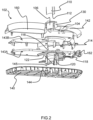
Fig.2 provides an exploded view of a support base of the steaming device, -
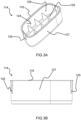
Figs.3A and 3B provide views of a cap that is included in a pole assembly, which pole assembly is mountable to the support base, -
Fig.4 provides a plan view of a pole support element of the support base, and -
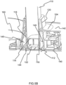
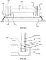
Figs.5A to 5F provide various views of the pole assembly mounted to the support base. -
Fig.1 depicts asteaming device 100 according to an example. Thesteaming device 100 comprises asupport base 102. Apole assembly 108 is detachably mountable to thesupport base 102. - The capability to supply the
pole assembly 108 detached from thesupport base 102 can assist to minimize the size of packaging required for transporting thesteaming device 100 and can facilitate transportation of thesteaming device 100. Being able to detach thepole assembly 108 from thesupport base 102 can also assist a user wishing to stow thesteaming device 100 in a storage area after use. - Referring to
Fig.2 , anupper portion 104 of thesupport base 102 delimits ahole 106. Thepole assembly 108 and thesupport base 102 are arranged such that thepole assembly 108 extends through thehole 106 and upstands from thesupport base 102 when thepole assembly 108 is mounted to thesupport base 102. - The
pole assembly 108, for example specifically thepole 110 included in thepole assembly 108, preferably contacts surface(s) of theupper portion 104 that delimit thehole 106. - Such contact can assist to reduce wobbling of the
pole assembly 108 when thepole assembly 108 is mounted to thesupport base 102. - In some embodiments, the
pole 110 is dimensioned to fit thehole 106 such that the surface(s) delimiting thehole 106 assist(s) to restrict movement of thepole 110 when thepole assembly 108 is mounted to thesupport base 102. - More generally, the
pole 110 is hollow at least at a lower portion of thepole 110, and acap 114 is received inside the lower portion of thepole 110 when thepole assembly 108 is assembled. - The
cap 114 can assist to ensure robust and stable mounting of thepole assembly 108 to thesupport base 102, as explained in more detail herein below. - The
steaming device 100 further includes apole support element 118. Thepole support element 118, when fixed to thesupport base 102, assists in mounting thepole assembly 108 to thesupport base 102. - The
pole 110 can have any suitable shape. In some embodiments, thepole 110 has a cross-sectional shape selected from the following: rectangular, rounded rectangular, square, rounded square, elliptical, or circular. - In some embodiments, the
pole 110 has an elongate cross-sectional shape, such as rectangular, rounded rectangular or elliptical. - In such embodiments, deformation along the sides of the
pole 110, corresponding to the longer dimension of the elongate cross-sectional shape, can potentially be significant, and can increase the risk of wobbling of thepole 110 when mounted to thesupport base 102. However, the manner of mounting thepole assembly 108 to thesupport base 102, as explained herein below, can assist to alleviate potential instability issues associated with the cross-sectional shape of thepole 110. - The
pole 110 can be formed of any suitable material. In some embodiments, thepole 110 is made of a metallic material. For example, thepole 110 is made of aluminium. Such analuminium pole 110 benefits from being relatively strong but also lightweight. - Difficulties can nonetheless be encountered with such an
aluminium pole 110, particularly in ensuring that manufacturing tolerances are consistently accurate. For example, abottom end 112 of thepole 110, at which the lower portion of thepole 110 terminates, may not easily fit into agroove 120 defined in thepole support element 118. This can compromise mounting of thepole 110 to thesupport base 102. However, the manner of mounting thepole assembly 108 to thesupport base 102, as explained herein below, can assist to alleviate such material-relatedpole 110 instability issues. - In view of the above-described technical challenges, the
pole support element 118 comprises aprotruding element 122. In at least some embodiments, such as that shown inFig.2 , the protrudingelement 122 upwardly protrudes in the direction of extension of thepole assembly 108 when thepole assembly 108 is mounted to thesupport base 102. - With reference to
Figs.2 ,3A and 3B , aninterior surface 124 of thecap 114 delimits ahollow portion 126 of thecap 114, and the protrudingelement 122 is receivable in thehollow portion 126 and dimensioned so that the protrudingelement 122 engages theinterior surface 124 of thecap 114. - The engagement of the protruding
element 122 with theinterior surface 124 of thecap 114 can assist to ensure robust and stable mounting of thepole assembly 108 to thesupport base 102. - In particular, the cap-protruding
element arrangement pole 110 of thepole assembly 108. Accordingly, various possibilities concerning the design of thepole 110 can be implemented with no or minimal compromise in terms of robust and stable mounting of thepole assembly 108 to thesupport base 102. For example, thepole 110 can be made of a metallic material, e.g. aluminium, and/or thepole 110 can have an elongate cross-sectional shape, such as rectangular, rounded rectangular or elliptical. - The engagement of the protruding
element 122 with theinterior surface 124 of thecap 114 can be regarded as at least partly defining an interference fit between thepole assembly 108 and thepole support element 118. - In other words, the interference fit between the
pole assembly 108 and thepole support element 118 can include theinterior surface 124 of thecap 114 and the protrudingelement 122 being pressed against each other. - In order to detach the
pole assembly 108 from thesupport base 102, the protrudingelement 122 can be removed from thehollow portion 126 of thecap 114, for example by pulling thepole 110 with sufficient force away from thesupport base 102, e.g. following release of apole fastening assembly 132 as described herein below. Thus, thepole 110, together with thecap 114, can be detached from thesupport base 102. - The
cap 114 can be made of any suitable material. In some embodiments, thecap 114 is made of one or more selected from a plastic material, such as an engineering thermoplastic, and a metallic material, such as aluminium. - For example, the
cap 114 is made of a moulded plastic material, such as a moulded engineering thermoplastic. In an alternative non-limiting example, thecap 114 is made of die cast aluminium. - In some embodiments, such as shown in
Figs.3A and 3B , thecap 114 includes one ormore fastening members 125, such as one or more snap-fit fastening members 125, for securing thecap 114 inside the lower portion of thepole 110. - For example, the fastening member(s) 125 include resiliently mounted protruding catch(es) that are each receivable in a recess or aperture defined in the lower portion of the
pole 110 in order to secure thecap 114 to the lower portion of thepole 110. - As an alternative or in addition to the fastening member(s) 125, an
exterior surface 127 of thecap 114 can contact, and thus frictionally engage with, an inner surface of the lower portion of thepole 110. - In some embodiments, and as shown in
Fig.3A , thecap 114 comprises aninternal reinforcement member 129. Theinternal reinforcement member 129 can assist to enhance the structural integrity of thecap 114. - The
internal reinforcement member 129 can have any suitable form/shape. In some embodiments, such as that shown inFig.3A , theinternal reinforcement member 129 comprises, e.g. is defined by, a grid mounted within thecap 114. - In some embodiments, and as best shown in
Fig.4 , the protrudingelement 122 comprises a plurality ofcrush ribs 128 arranged around the protrudingelement 122. In such embodiments, theinterior surface 124 of thecap 114 and thecrush ribs 128 are pressed against each other when the protrudingelement 122 is received in thehollow portion 126. - Thus, the engagement of the protruding
element 122 with theinterior surface 124 of thecap 114 can include, e.g. be defined by, engagement of thecrush ribs 128 of the protrudingelement 122 with theinterior surface 124 of thecap 114. - The
crush ribs 128 interfering with theinterior surface 124 of thecap 114 can assist to restrict movement of thepole assembly 108 when thepole assembly 108 is mounted to thesupport base 102. - As shown in
Fig.4 , thecrush ribs 128 are preferably distributed around a perimeter of the protrudingelement 122. This distribution of thecrush ribs 128 can assist to minimize gaps at the interface between thepole assembly 108 and thepole support element 118 when thepole assembly 108 is mounted to thesupport base 102. - More generally, and referring to
Figs.3A and4 , thehollow portion 126 preferably has a cross-sectional shape that complements a profile of the protrudingelement 122. - Thus, the protruding
element 122 can fit snuggly inside thehollow portion 126, with concomitant enhancement of stability of mounting of thepole assembly 108 to thesupport base 102. - In some embodiments, such as shown in
Figs.1 ,2 ,5A ,5B and5E , theupper portion 104 of thesupport base 102 comprises a mountingboss 130 for supporting thepole 110. The mountingboss 130 upwardly projects in the direction of extension of thepole assembly 108 from thesupport base 102 when thepole assembly 108 is mounted to thesupport base 102, as best shown inFigs.2 ,5A and5B . - In such embodiments, the
hole 106 through which thepole assembly 108 passes when thepole assembly 108 is mounted to thesupport base 102 extends through the mountingboss 130. The mountingboss 130 can thus assist to increase the length over which thepole assembly 108 is supportable by thesupport base 102. - The
pole assembly 108, for example specifically thepole 110 included in thepole assembly 108, preferably contacts inner surface(s) 138 of the mountingboss 130 that delimit(s) thehole 106. An example of this is best shown inFig.5F . - In such embodiments, the mounting
boss 130 assists to increase the length over which thepole assembly 108 contacts thesupport base 102. This, in turn, can enhance the stability of thepole assembly 108 when thepole assembly 108 is mounted to thesupport base 102. - The
arrows 131 inFig.5A point to areas of tight contact between thepole 110 and the inner surface(s) 138 of the mountingboss 130 that delimit(s) thehole 106. - In some embodiments, and as best shown in
Figs.5E and 5F , thesteaming device 100 comprises apole fastening assembly 132 for releasably fastening thepole 110 to thesupport base 102. - Securing the
pole 110 at a distance from the bottom end of thepole 110 in this way, in addition to the bottom end being secured via the protrudingelement 122 of thepole support element 118 being received in thehollow portion 126 of thecap 114, can significantly improve the rigidity of the interface between thepole assembly 108 and thesupport base 102. - In such embodiments, the
pole fastening assembly 132 preferably includes a pushingmember 134 coupled to thesupport base 102, and acam lever 136 pivotable between a locking position, as shown inFigs.5E and 5F , in which thecam lever 136 exerts a force on the pushingmember 134 that causes the pushingmember 134 to push against thepole 110, and a releasing position in which the force is released. - Such a
pole fastening assembly 132, which can be alternatively termed a "cam lock", can assist to minimize or prevent movement of thepole assembly 108 when thepole assembly 108 is mounted to thesupport base 102. - The force on the pushing
member 134 can cause thepole 110 to be squeezed between the pushingmember 134 and surface(s) of theupper portion 104 of thesupport base 102 that delimit(s) thehole 106. - When the
cam lever 136 is in the releasing position, thepole assembly 108 can be detached from thesupport base 102, in particular by causing the protrudingelement 122 to be removed from thehollow portion 126 of thecap 114, as previously described. - In embodiments in which the
upper portion 104 of thesupport base 102 comprises the mountingboss 130, the pushingmember 134 is preferably arranged such that, when thecam lever 136 is positioned to exert the force on the pushingmember 134 that causes the pushingmember 134 to push against thepole 110, thepole 110 is squeezed between the pushingmember 134 and the inner surface(s) 138 of the mountingboss 130. - The cam lock can thus assist to minimize or avoid gap(s) between the
pole 110 and the mountingboss 130, and thereby reduce wobbling of thepole assembly 108 when thepole assembly 108 is mounted to thesupport base 102. - The pushing
member 134 can be made of any suitable material. In some embodiments, the pushingmember 134 is made of a plastic material, such as an engineering thermoplastic. - When the pushing
member 134 is made of a plastic material, it can take the form of a plastic block that is movable by thecam lever 136 against thepole 110. - As shown in
Figs.5E and 5F , apivot coupling 137 couples thecam lever 136 to thesupport base 102 and enables pivoting of thecam lever 136 between the locking position and the releasing position. - In some embodiments, and referring to
Figs.2 ,5A and5B , thesupport base 102 comprises alower shell 140 and anupper shell 142 attached to thelower shell 140, with theupper shell 142 comprising theupper portion 104 of thesupport base 102 that delimits thehole 106. In such embodiments, a space is defined between thelower shell 140 and theupper shell 142, and at least part of thepole support element 118 is arranged within the space. - In some embodiments, such as shown in
Fig.2 , thesupport base 102 comprises aballast housing support base 102. - Such ballast assists to lower the centre of gravity of the
steaming device 100, and thus assists to make thesteaming device 100 more stable. - The
ballast housing ballast housing portion 143A and an upperballast housing portion 143B, with the ballast being housed between the lowerballast housing portion 143A and the upperballast housing portion 143B. - In some embodiments, at least part of the
ballast housing lower shell 140 and theupper shell 142. - Preferably, the
pole support element 118 is attached to thelower shell 140 and/or to theupper shell 142. - The
pole support element 118 can be attached, e.g. rigidly coupled, to thelower shell 140 and/or to theupper shell 142 in any suitable manner. For example, one or more fasteners, e.g. screw(s), can be used to attach thepole support element 118 to thelower shell 140 and/or to theupper shell 142. - Such fastener(s), e.g. screw(s), can assist to minimize or prevent movement of the
pole support element 118 within thesupport base 102. - Alternatively or additionally, the
lower shell 140 preferably comprises a mountingstructure 144 arranged around and adapted to press against thepole support element 118. - In some embodiments, and as best shown in
Figs.2 ,5A ,5B and5C , the mountingstructure 144 comprises, e.g. is defined by, an annular protrusion provided on thelower shell 140. - Such an annular protrusion preferably extends into an
annular cavity 145 provided in thepole support element 118. This can help to minimize movement of thepole support element 118 within thesupport base 102. - The
arrows 147A inFigs.5A and5C point to areas of tight contact between mountingstructure 144 and thepole support element 118. - It is noted that the
arrows 147B inFig.5A point to areas of contact between the mountingstructure 144 and thepole support element 118 that may be less critical for minimizing wobbling of thepole assembly 108 when mounted to thesupport base 102, due to the tight contacts pointed to by thearrows - In some embodiments, and as best shown in
Figs.3A, 3B and5A to 5F , thecap 114 has arim portion 116 that protrudes from thebottom end 112 of thepole 110, and therim portion 116 is receivable in thegroove 120 defined in thepole support element 118. - Referring to
Fig.2 , thegroove 120 extends around the protrudingelement 122. Thus, therim portion 116 is receivable in thegroove 120 when the protrudingelement 122 is received in thehollow portion 126 of thecap 114. - In such embodiments, the
groove 120 is preferably provided between theprotruding element 122 and anouter part 149 of thepole support element 118 that extends to reach, and is attached to, theupper shell 142 and/or thelower shell 140. - In other words, a leg defined by the
outer part 149 of thepole support element 118 can couple theprotruding element 122 to theupper shell 142 and/or thelower shell 140. - In some embodiments, and as shown in
Fig.5D , a first surface S1 and a second surface S2 of thepole support element 118 face each other across thegroove 120, and therim portion 116 is arranged to contact one or both of the first surface S1 and the second surface S2 when therim portion 116 is received in thegroove 120. - Thus, the interference fit between the
pole assembly 108 and thepole support element 118 can include therim portion 116 and surface(s) S1, S2 of thepole support element 118 delimiting thegroove 120 being pressed against each other. - In other words, the
rim portion 116, e.g. anannular rim portion 116, can be mounted tightly in thegroove 120 when thepole assembly 108 is mounted to thesupport base 102. - Referring to the non-limiting example shown in the Figures, the first surface S1 is a surface of the
outer part 149 of thepole support element 118 that faces the protrudingelement 122, and the second surface S2 is a surface of the protrudingelement 122 that faces the surface of theouter part 149. - In a non-limiting illustrative example, the
cap 114 is made of plastic material and is arranged in the lower portion of thepole 110 which is made of aluminium, with therim portion 116 that protrudes from thebottom end 112 of thealuminium pole 110 fitting tightly inside thegroove 120 defined in thepole support element 118. - In some embodiments, and referring again to
Fig.1 , thepole assembly 108 is atelescopic pole assembly 108 that comprises thepole 110 and anupper pole 146, with theupper pole 146 being slidable out of and into an upper end of thepole 110 to enable extension and collapsing of thetelescopic pole assembly 108. - The effect of any gaps at the interface between such a
telescopic pole assembly 108 and thesupport base 102, e.g. at thehole 106, on stability can be amplified by extension of thetelescopic pole assembly 108. Thus, there is a greater risk of theextended pole assembly 108 being perceived as being wobbly during ironing or steaming using thesteaming device 100. The robust and stable mounting of thepole assembly 108 to thesupport base 102 via the cap-protrudingelement arrangement pole assembly 108 is such atelescopic pole assembly 108. - In some embodiments, and referring again to
Fig. 1 , thesteaming device 100 comprises anironing board 148, with theironing board 148 being supportable by thepole assembly 108 and thesupport base 102. Thus, theironing board 148 can provided to the user along with thesupport base 102 and thepole assembly 108. - In embodiments in which the
pole assembly 108 is atelescopic pole assembly 108, extension and collapsing of thetelescopic pole assembly 108 can enable height adjustment of theironing board 148. - As an alternative or in addition to being telescopic, the
pole assembly 108 can be configured to enable tilting of theironing board 148, for example between a vertical orientation and a horizontal orientation, as shown inFig. 1 . - The vertical orientation of the
ironing board 148 can be utilized for steaming hanging garments, e.g. garments hanging from a hanger, and the horizontal orientation of theironing board 148 can be used for ironing garments. - In at least some embodiments, and with continued reference to
Fig. 1 , thesteaming device 100 comprises abase unit 150 comprising a water tank, asteamer head 152 having a treatment plate delimiting at least one steam vent, and ahose cord 154 connecting thebase unit 150 to thesteamer head 152. - The
steaming device 100 shown inFig.1 can be regarded as astand garment steamer 100. - In some embodiments, the
base unit 150 comprises a steam generator (not visible) and thesteamer head 152 comprises a steam chamber arranged to re-heat the steam and/or vaporise heated water received from the steam generator, prior to the steam exiting thesteamer head 152 via the at least one steam vent. - In alternative embodiments, the
steamer head 152 comprises a steam chamber arranged to generate steam from water supplied, e.g. pumped, thereto from the water tank included in thebase unit 150. - In some embodiments, such as that shown in
Fig. 1 , thesteaming device 100 includes acradle 156 on which thesteamer head 152 is dockable when thesteamer head 152 is not being moved by the user. Thecradle 156 is preferably attachable to theironing board 148 via asupport arm 158. - In some embodiments, the
support base 102 is arranged to support thebase unit 150. Thus, thebase unit 150 can be supported by thesupport base 102 to which thepole assembly 108 is detachably mountable. - In such embodiments, and referring to
Figs.2 and5B , thesupport base 102 preferably includes a recessedarea 160 in which thebase unit 150 is receivable in order to be supported by thesupport base 102. - For example, the recessed
area 160 has a shape that complements an exterior profile of thebase unit 150. - Such a complementarily shaped recessed
area 160 can assist to prevent thebase unit 150 from being accidentally knocked over during use of thesteaming device 100. - In some embodiments, such as shown in
Fig.2 , thesupport base 102 comprises one ormore wheels 162 to assist with manoeuvring of thesupport base 102, e.g. across a floor. - The wheel(s) 162 can be rotatably mounted in any suitable manner. The wheel(s) are preferably rotatably mounted to the
ballast housing ballast housing portion 143A. - The above embodiments as described are only illustrative, and not intended to limit the technique approaches of the present invention. Although the present invention is described in details referring to the preferable embodiments, those skilled in the art will understand that the technique approaches of the present invention can be modified or equally displaced without departing from the protective scope of the claims of the present invention. In particular, although the invention has been described based on a steaming device, it can be applied to any type of device, e.g. household device, having a pole assembly that is detachably mountable to a support base. In the claims, the word "comprising" does not exclude other elements or steps, and the indefinite article "a" or "an" does not exclude a plurality. Any reference signs in the claims should not be construed as limiting the scope.
Claims (15)
- A steaming device (100) comprising:a. a support base (102) having an upper portion (104), the upper portion delimiting a hole (106),b. a pole assembly (108) being detachably mountable to the support base, the pole assembly and the support base being arranged such that the pole assembly extends through the hole and upstands from the support base when the pole assembly is mounted to the support base, wherein the pole assembly comprises:i- a pole (110) being hollow at least at a lower portion of the pole, andii- a cap (114) being arranged inside the lower portion of the pole, an interior surface (124) of the cap delimiting a hollow portion (126) of the cap, andc. a pole support element (118) fixed to the support base, the pole support element comprising a protruding element (122), the protruding element being receivable in the hollow portion and dimensioned so that the protruding element engages with the interior surface of the cap.
- The steaming device (100) according to claim 1, wherein:- the lower portion of the pole (110) terminates at a bottom end (112) of the pole,- the cap (114) has a rim portion (116) that protrudes from the bottom end of the pole,- a groove (120) is defined in the pole support element (118), the groove extending around the protruding element (122), and- the rim portion is receivable in the groove when the protruding element is received in the hollow portion (126).
- The steaming device (100) according to claim 2, wherein:- a first surface (S1) and a second surface (S2) of the pole support element (118) face each other across the groove (120), and- the rim portion (116) is arranged to contact one or both of the first surface and the second surface when the rim portion is received in the groove.
- The steaming device (100) according to any one of claims 1 to 3, wherein the protruding element (122) comprises a plurality of crush ribs (128) arranged around the protruding element, the interior surface (124) of the cap (114) and the crush ribs being pressed against each other when the protruding element (122) is received in the hollow portion (126).
- The steaming device (100) according to any one of claims 1 to 4, wherein the upper portion (104) of the support base (102) comprises a mounting boss (130) for supporting the pole (110), the hole (106) extending through the mounting boss.
- The steaming device (100) according to any one of claims 1 to 5, comprising a pole fastening assembly (132) including:- a pushing member (134) coupled to the support base (102), and- a cam lever (136) pivotable between a locking position in which the cam lever exerts a force on the pushing member that causes the pushing member to push against the pole (110), and a releasing position in which said force is released.
- The steaming device (100) according to claim 6 when dependent from claim 5, wherein the pushing member (134) is arranged such that, when the cam lever (136) is positioned to exert said force, the pole (110) is squeezed between the pushing member and an inner surface (138) of the mounting boss (130).
- The steaming device (100) according to any one of claims 1 to 7, wherein:- the support base (102) comprises a lower shell (140) and an upper shell (142) attached to the lower shell,- the upper shell comprises said upper portion (104) of the support base,- a space is defined between the lower shell and the upper shell, and- at least part of the pole support element (118) is arranged within said space.
- The steaming device (100) according to claim 8, wherein the pole support element (118) is attached to the lower shell (140) and/or to the upper shell (142).
- The steaming device (100) according to claim 8 or claim 9, wherein the lower shell (140) comprises a mounting structure (144) arranged around and adapted to press against the pole support element (118).
- The steaming device (100) according to any one of claims 1 to 10, wherein the pole (110) has a cross-sectional shape selected from the following:- rectangular,- rounded rectangular- square,- rounded square,- elliptical, or- circular.
- The steaming device (100) according to any one of claims 1 to 11, wherein the pole (110) is made of a metallic material.
- The steaming device (100) according to any one of claims 1 to 12, wherein the pole assembly (108) is a telescopic pole assembly that comprises the pole (110) and an upper pole (146), the upper pole being slidable out of and into an upper end of the pole to enable extension and collapsing of the telescopic pole assembly.
- The steaming device (100) according to any one of claims 1 to 13, comprising an ironing board (148), the ironing board being supportable by the pole assembly (108) and the support base (102).
- The steaming device (100) according to any one of claims 1 to 14, comprising:- a base unit (150) comprising a water tank,- a steamer head (152) having a treatment plate delimiting at least one steam vent, and- a hose cord (154) connecting the base unit to the steamer head; optionally wherein the support base (102) is arranged to support the base unit.
Priority Applications (5)
| Application Number | Priority Date | Filing Date | Title |
|---|---|---|---|
| EP23151365.6A EP4400643A1 (en) | 2023-01-12 | 2023-01-12 | Steaming device comprising a pole assembly and a support base |
| CN202380091064.4A CN120548391A (en) | 2023-01-12 | 2023-12-04 | Steam handling apparatus including a rod assembly and a support base |
| EP23821148.6A EP4649188A1 (en) | 2023-01-12 | 2023-12-04 | Steaming device comprising a pole assembly and a support base |
| KR1020257026603A KR20250134115A (en) | 2023-01-12 | 2023-12-04 | A steaming device including a pole assembly and a support base |
| PCT/EP2023/084088 WO2024149519A1 (en) | 2023-01-12 | 2023-12-04 | Steaming device comprising a pole assembly and a support base |
Applications Claiming Priority (1)
| Application Number | Priority Date | Filing Date | Title |
|---|---|---|---|
| EP23151365.6A EP4400643A1 (en) | 2023-01-12 | 2023-01-12 | Steaming device comprising a pole assembly and a support base |
Publications (1)
| Publication Number | Publication Date |
|---|---|
| EP4400643A1 true EP4400643A1 (en) | 2024-07-17 |
Family
ID=84943303
Family Applications (2)
| Application Number | Title | Priority Date | Filing Date |
|---|---|---|---|
| EP23151365.6A Withdrawn EP4400643A1 (en) | 2023-01-12 | 2023-01-12 | Steaming device comprising a pole assembly and a support base |
| EP23821148.6A Pending EP4649188A1 (en) | 2023-01-12 | 2023-12-04 | Steaming device comprising a pole assembly and a support base |
Family Applications After (1)
| Application Number | Title | Priority Date | Filing Date |
|---|---|---|---|
| EP23821148.6A Pending EP4649188A1 (en) | 2023-01-12 | 2023-12-04 | Steaming device comprising a pole assembly and a support base |
Country Status (4)
| Country | Link |
|---|---|
| EP (2) | EP4400643A1 (en) |
| KR (1) | KR20250134115A (en) |
| CN (1) | CN120548391A (en) |
| WO (1) | WO2024149519A1 (en) |
Citations (4)
| Publication number | Priority date | Publication date | Assignee | Title |
|---|---|---|---|---|
| CN206858897U (en) * | 2017-07-07 | 2018-01-09 | 黄春香 | Ironing board arrangement for adjusting height and the intelligent clothing care machine using the device |
| CN108118517A (en) * | 2018-02-09 | 2018-06-05 | 苏州市格美纳电器有限公司 | A kind of ironing table and apply its Garment Steamer Machine |
| CN213624882U (en) * | 2020-10-26 | 2021-07-06 | 浙江绍兴苏泊尔生活电器有限公司 | Hanging ironing machine |
| EP3783171B1 (en) * | 2019-08-22 | 2022-01-19 | Seb S.A. | Device for treating laundry |
-
2023
- 2023-01-12 EP EP23151365.6A patent/EP4400643A1/en not_active Withdrawn
- 2023-12-04 KR KR1020257026603A patent/KR20250134115A/en active Pending
- 2023-12-04 EP EP23821148.6A patent/EP4649188A1/en active Pending
- 2023-12-04 WO PCT/EP2023/084088 patent/WO2024149519A1/en not_active Ceased
- 2023-12-04 CN CN202380091064.4A patent/CN120548391A/en active Pending
Patent Citations (4)
| Publication number | Priority date | Publication date | Assignee | Title |
|---|---|---|---|---|
| CN206858897U (en) * | 2017-07-07 | 2018-01-09 | 黄春香 | Ironing board arrangement for adjusting height and the intelligent clothing care machine using the device |
| CN108118517A (en) * | 2018-02-09 | 2018-06-05 | 苏州市格美纳电器有限公司 | A kind of ironing table and apply its Garment Steamer Machine |
| EP3783171B1 (en) * | 2019-08-22 | 2022-01-19 | Seb S.A. | Device for treating laundry |
| CN213624882U (en) * | 2020-10-26 | 2021-07-06 | 浙江绍兴苏泊尔生活电器有限公司 | Hanging ironing machine |
Also Published As
| Publication number | Publication date |
|---|---|
| CN120548391A (en) | 2025-08-26 |
| KR20250134115A (en) | 2025-09-09 |
| EP4649188A1 (en) | 2025-11-19 |
| WO2024149519A1 (en) | 2024-07-18 |
Similar Documents
| Publication | Publication Date | Title |
|---|---|---|
| EP4649188A1 (en) | Steaming device comprising a pole assembly and a support base | |
| WO2024179708A1 (en) | Accessory and garment steamer comprising the same | |
| KR101447138B1 (en) | Rovingness sprayer | |
| JP3751417B2 (en) | Pump with lock | |
| CN106222980B (en) | Clothes hanger | |
| EP4573241B1 (en) | Telescopic pole assembly for supporting an ironing board | |
| CN109625546B (en) | Storage box for ironing machine | |
| EP4647545A1 (en) | Stand steamer comprising support base and detachable water tank | |
| WO2024088512A1 (en) | Detachable docking unit for a garment steamer | |
| CN219720388U (en) | Cooking utensil | |
| CN215724188U (en) | Inner container fixing assembly and electric water heater | |
| EP4647544A1 (en) | Garment steamer comprising pole(s)-supported ironing board | |
| CN215210115U (en) | Water tank with telescopic structure for ironing machine and portable steam ironing machine | |
| WO2015024186A1 (en) | Fan | |
| CN224125700U (en) | Cooking apparatus | |
| CN220917145U (en) | Electric heating thermos bottle with built-in handle | |
| CN219720244U (en) | Bedstead and crib | |
| CN217429760U (en) | Electric saucepan | |
| CN210433305U (en) | Portable electric heating pot | |
| CN219720385U (en) | Cooking utensil | |
| CN223860617U (en) | Water dispenser | |
| CN222340792U (en) | Movable coffee table | |
| CN212308504U (en) | Stable rib cuff sterilization safety rack | |
| JP2560858Y2 (en) | Lifting device for handle rod in stroller | |
| JPH0534608Y2 (en) |
Legal Events
| Date | Code | Title | Description |
|---|---|---|---|
| PUAI | Public reference made under article 153(3) epc to a published international application that has entered the european phase |
Free format text: ORIGINAL CODE: 0009012 |
|
| STAA | Information on the status of an ep patent application or granted ep patent |
Free format text: STATUS: THE APPLICATION HAS BEEN PUBLISHED |
|
| AK | Designated contracting states |
Kind code of ref document: A1 Designated state(s): AL AT BE BG CH CY CZ DE DK EE ES FI FR GB GR HR HU IE IS IT LI LT LU LV MC ME MK MT NL NO PL PT RO RS SE SI SK SM TR |
|
| STAA | Information on the status of an ep patent application or granted ep patent |
Free format text: STATUS: THE APPLICATION IS DEEMED TO BE WITHDRAWN |
|
| 18D | Application deemed to be withdrawn |
Effective date: 20250118 |