EP4400642A1 - Washing machine with improved shock absorber fixation and process for its manufacture - Google Patents
Washing machine with improved shock absorber fixation and process for its manufacture Download PDFInfo
- Publication number
- EP4400642A1 EP4400642A1 EP24150999.1A EP24150999A EP4400642A1 EP 4400642 A1 EP4400642 A1 EP 4400642A1 EP 24150999 A EP24150999 A EP 24150999A EP 4400642 A1 EP4400642 A1 EP 4400642A1
- Authority
- EP
- European Patent Office
- Prior art keywords
- washing machine
- bottom plate
- shock absorber
- holes
- central opening
- Prior art date
- Legal status (The legal status is an assumption and is not a legal conclusion. Google has not performed a legal analysis and makes no representation as to the accuracy of the status listed.)
- Pending
Links
- 230000035939 shock Effects 0.000 title claims abstract description 65
- 239000006096 absorbing agent Substances 0.000 title claims abstract description 63
- 238000005406 washing Methods 0.000 title claims abstract description 51
- 238000000034 method Methods 0.000 title claims abstract description 22
- 230000008569 process Effects 0.000 title claims abstract description 22
- 238000004519 manufacturing process Methods 0.000 title claims abstract description 10
- XLYOFNOQVPJJNP-UHFFFAOYSA-N water Substances O XLYOFNOQVPJJNP-UHFFFAOYSA-N 0.000 claims abstract description 19
- 238000004049 embossing Methods 0.000 claims description 16
- 238000005520 cutting process Methods 0.000 claims description 5
- 229910000831 Steel Inorganic materials 0.000 claims description 4
- 239000010959 steel Substances 0.000 claims description 4
- 230000003014 reinforcing effect Effects 0.000 description 7
- 230000008901 benefit Effects 0.000 description 3
- 238000009826 distribution Methods 0.000 description 3
- 230000008859 change Effects 0.000 description 2
- 239000000463 material Substances 0.000 description 2
- 230000002093 peripheral effect Effects 0.000 description 2
- 238000005452 bending Methods 0.000 description 1
- 238000006243 chemical reaction Methods 0.000 description 1
- 238000010276 construction Methods 0.000 description 1
- 230000008878 coupling Effects 0.000 description 1
- 238000010168 coupling process Methods 0.000 description 1
- 238000005859 coupling reaction Methods 0.000 description 1
- 230000001419 dependent effect Effects 0.000 description 1
- 230000009975 flexible effect Effects 0.000 description 1
- 230000006872 improvement Effects 0.000 description 1
- 238000012423 maintenance Methods 0.000 description 1
- 239000002184 metal Substances 0.000 description 1
- 230000000149 penetrating effect Effects 0.000 description 1
- 230000035515 penetration Effects 0.000 description 1
- 239000002994 raw material Substances 0.000 description 1
- 230000003252 repetitive effect Effects 0.000 description 1
- 230000007704 transition Effects 0.000 description 1
- 238000003466 welding Methods 0.000 description 1
Images


Classifications
-
- D—TEXTILES; PAPER
- D06—TREATMENT OF TEXTILES OR THE LIKE; LAUNDERING; FLEXIBLE MATERIALS NOT OTHERWISE PROVIDED FOR
- D06F—LAUNDERING, DRYING, IRONING, PRESSING OR FOLDING TEXTILE ARTICLES
- D06F37/00—Details specific to washing machines covered by groups D06F21/00 - D06F25/00
- D06F37/20—Mountings, e.g. resilient mountings, for the rotary receptacle, motor, tub or casing; Preventing or damping vibrations
- D06F37/22—Mountings, e.g. resilient mountings, for the rotary receptacle, motor, tub or casing; Preventing or damping vibrations in machines with a receptacle rotating or oscillating about a horizontal axis
-
- D—TEXTILES; PAPER
- D06—TREATMENT OF TEXTILES OR THE LIKE; LAUNDERING; FLEXIBLE MATERIALS NOT OTHERWISE PROVIDED FOR
- D06F—LAUNDERING, DRYING, IRONING, PRESSING OR FOLDING TEXTILE ARTICLES
- D06F39/00—Details of washing machines not specific to a single type of machines covered by groups D06F9/00 - D06F27/00
- D06F39/12—Casings; Tubs
Definitions
- the invention relates to a washing machine with an improved shock absorber fixation and a process for its manufacture.
- the invention relates more particularly to a washing machine comprising a housing with a water tub in which a drum is rotatable arranged, at least one shock absorber to support the water tub; and a shock absorber fixing unit arranged on a bottom plate of the housing to secure the shock absorber at a fixed position; and a process for the manufacture of this washing machine.
- Japanese Patent Publication No. Heisei 5-253387 discloses a drum type washing machine comprising at least one damper (herein especially referred to as "shock absorber”) for supporting a lower portion of a water tub and reducing vibration and shaking caused in the water tub.
- the damper has an upper end coupled to the lower portion of the water tub and a lower end secured to a bottom plate of a washing machine body, and serves to reduce vibration and shaking caused in the water tub by a flexible action thereof.
- the disclosed washing machine comprises a specific shock absorber fixing unit disposed on the bottom plate of the body and adapted to secure the lower end of the damper. The lower end of the damper and the shock absorber fixing unit are coupled to each other by use of fixing bolts.
- the shock absorber fixing unit is conventionally attached to the bottom plate of the body by welding, or formed by cutting a portion of the bottom plate.
- the shock absorber fixing unit includes first and second fixing pieces extending from the bottom plate of the body to opposite sides of the lower end of the damper, respectively, each fixing piece having a bolt penetrating hole.
- the shock absorber fixing unit of a common washing machine has however the problem that a part thereof connected to the bottom plate of the housing is fragile, and therefore, the shock absorber fixing unit and the peripheral region thereof may be damaged by repetitive vibration and shock applied thereto.
- the shock absorber fixing unit is formed by cutting a portion of the bottom plate of the body, a boundary between the cut portion of the bottom plate and the shock absorber fixing unit is fragile, thus having a high risk of damage.
- the publication EP 1 760 183 A2 discloses a drum type washing machine comprising: a body; a water tub installed in the body; at least one damper to support the water tub; and a shock absorber fixing unit arranged on a bottom plate of the body to secure the damper at a fixed position; wherein the shock absorber fixing unit is formed via cutting of the bottom plate, and has a reinforced rigidity by a reinforcing portion formed around the cut portion of the bottom plate.
- the reinforcing portion is formed by bending a peripheral portion around the cut portion to have a height larger than a thickness of the bottom plate, and is integrally formed with the shock absorber fixing unit.
- the reinforcing portion is bent from a periphery of the cut portion to protrude upward from an upper surface of the bottom plate, and is integrally formed with the shock absorber fixing unit.
- the shock absorber fixing unit comprises first and second fixing pieces, which are cut from the bottom plate and bent upward to support opposite sides of a lower end of the damper, each fixing piece having a hole for the penetration of a fixing bolt.
- a washing machine comprising: a main body in which a tub is installed, and having a bottom plate; a damper provided in the main body to support the tub; and a damper fixing member, provided on the bottom plate to fix the damper to the bottom plate, comprising: a bolt, a first flange portion on the bottom plate to support a first side of a lower end of the damper and provided with a through hole through which the bolt passes, a second flange portion on the bottom plate and facing the first flange portion to support a second side of the lower end of the damper, and provided with a coupling portion to which the bolt is fastened, and a reinforcing rib on the first flange portion or the second flange portion.
- the reinforcing rib protrudes from the first flange portion or the second flange portion which the reinforcing rib is on. It is furthermore disclosed that the hole formed on the first flange portion may be a through hole through which the fixing bolt passes, and the hole formed on the second flange portion may be provided with threads to fix the fixing bolt.
- the used shock absorber fixing unit allows the construction of the washing machine with less material although the stability is not worsened.
- the washing machine should be capable of preventing damage to a shock absorber fixing unit.
- a further object was the provision of a process for manufacturing this washing machine.
- washing machine and the process for its manufacture pursuant to the independent claims.
- Preferred embodiments of the washing machine according to the invention are indicated in the dependent claims.
- Preferred embodiments of the process correspond to preferred embodiments of the washing machine and vice versa, even if not expressly stated herein.
- the invention is thus directed to a washing machine comprising a housing with a water tub in which a drum is rotatable arranged, at least one shock absorber to support the water tub; and a shock absorber fixing unit arranged on a bottom plate of the housing to secure the shock absorber per at a fixed position; wherein the shock absorber fixing unit comprises a three-dimensional structure with a central opening protruding from the bottom plate, the three-dimensional structure having a continuous round neck around the central opening that is inclined towards the central opening, and two flap portions with holes which extend from opposite sides of the neck.
- the shock absorber fixing unit has essentially a cut portion in the bottom plate and an improved reinforcing portion formed around the cut portion of the bottom plate. There are thus also no discontinuities in the neck since there is a continuous change of curvature away from the bottom plate.
- the shock absorber can be secured to the shock absorber fixing unit by introducing and fixing a suitable bolt through the hole of the first flap, a hole at the lower end of the shock absorber and the hole in the second flap element.
- a washing machine contains usually at least two shock absorbers, in general three or four shock absorbers.
- the washing machine of the present invention contains preferably three or four of the shock absorber fixing units described herein.
- the shock absorber fixing unit is arranged on a bottom plate. Any plate located on the bottom part of the housing is understood as a bottom plate. It is understood as a bottom part of the housing any part of the housing located under the lowest point of the water tub.
- the bottom plate can be arranged either vertically or horizontally, the horizontal position being the preferred position.
- the bottom plate can cover the bottom side of the housing partially or completely.
- the washing machine can be a washing machine as such or a wash-dryer that combines the functions of a washing machine and a dryer.
- the washing machine is in general adapted to treat laundry items, which are kept in the drum.
- the neck has a round base area.
- the round base area has preferably a short side and a long side, wherein the two flap elements are preferably arranged along the long sides.
- the holes have a round shape.
- a round shape avoids stress points that can become breaking points.
- a washing machine is moreover preferred, wherein the round holes have the shape of circles. It is then more preferable that the circle shaped holes have a common perpendicular axis that passes through the centers of both circle shaped holes.
- the round holes have a size corresponding to a circle with a diameter d in the range of from 4 to 11 mm, preferably of from 6 to 9 mm.
- the holes in the flaps are circular and have the same diameter.
- a washing machine is moreover preferred wherein one flap portion is provided with a thread around its round hole.
- the damper can thus allow its fixation at its lower end by introducing a bolt through an opening at the lower end of the damper and the round holes in the flaps in an improved manner.
- a distance h between the bottom plate and the center of each of the round holes in the flap portions is in the range of from to 1.0 to 2.5 cm, preferably 1.2 to 2.3 cm. In case several embossment steps have been carried out on the bottom plate, the distance h is measured from the highest located essentially plane part of the embossed bottom plate.
- a washing machine is moreover preferred, wherein the bottom plate is made from steel and has a thickness in the range of from 0.5 bis 2 mm, preferably 0.6 to 1.8 mm, in particular 0.7 to 1.5 mm. Following thicknesses 0.8 mm, 0.9 mm, 1 mm, 1.1 mm, 1.2 mm, 1.3 mm and 1.4 mm are also preferred.
- the invention is moreover directed to a process for the manufacture of a washing machine comprising a housing with a water tub in which a drum is rotatable arranged, at least one shock absorber to support the water tub; and a shock absorber fixing unit arranged on a bottom plate of the housing to secure the shock absorber at a fixed position; wherein the shock absorber fixing unit comprises a three-dimensional structure with a central opening protruding from the bottom plate, the three-dimensional structure having a continuous round neck around the central opening that is inclined towards the central opening, and two flap portions with holes which extend from opposite sides of the neck, the process comprising the steps:
- the holes have a round shape.
- a thread is provided around at least one of the holes after the step e) providing two holes in the two flap elements.
- a thread at one round opening in a flap portion is formed by deformation through the application of pressure, which creates the thread without scrap. Accordingly, the thread is preferably not an extra piece.
- the round holes are in general aligned for receiving a bolt through them such that for securing a damper in the shock absorber fixing unit of the washing machine, a suitable bolt can be introduced and fixed through the hole of the first flap, a hole at the lower end of the shock absorber and the hole in the second flap portion.
- a die bends faces, i.e. the flaps, from an inclined angle into 90°.
- step (e) the two holes are preferably introduced in separate steps in order to avoid deformation.
- the present invention provides several advantages. Advantages of the invention include a better distribution of stress, in particular tensile stress distribution, in such a way that there are no local stress concentration points. Thus the tendency for deformation and cracks in the shock absorber fixation can be significantly reduced. Additionally, a more robust design can be realized because the hole size can be made significantly smaller. In this manner, the system is less sensible to possible material or process variations n improvement of the utilization of. Another advantage is that the height h can be reduced significantly. This is important, because the lower h, the lower the momentum will be such that there is less stress on the bottom strut.
- the invention allows to reduce thickness and thus provides an economic saving.
- the present invention allows the same stackability than present embossed bottom plates. This allows to keep the same stacking capacity of the feeder.
- the invention allows that the shock absorber bracket is in a comparatively lower position, which reduces momentum.
- the invention allows in addition that the hole in a bottom strut is comparatively small, so the bottom strut is in general more robust.
- the process of the present invention is also more robust.
- the process is less sensible to variations of all parameters needed to manufacture the part. It is less sensible to variations of raw material properties, or tool maintenance, etc.
- a process relying on merely flaps is more sensible to process changes.
- the present invention allows to reduce the complexity of the manufacture in that the number of parts used per household appliance can be reduced.
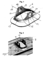
- Fig. 1 thus shows the three-dimensional structure 6 with a central opening 7 protruding from a bottom plate not shown here.
- the three-dimensional structure 6 has a continuous round neck 8 around the central opening 7 that is inclined towards the central opening 7, and two flap portions 9,10 with round holes 11,12 which extend from opposite sides of the neck 8.
- the neck 8 has a round base area 13.
- the round holes 11,12 have the shape of circles and have a common perpendicular axis 14 that passes through the centers 15 of both circle shaped holes 11,12.
- the round holes 11,12 have a diameter d in the range of from 6 to 9 mm.
- One flap portion 9 is provided with a thread 16 around its round hole.
- Fig. 2 shows a perspective view on the exemplary three-dimensional structure of Fig. 1 as present on a shown bottom plate 17,5.
- an upper part 17 of the original bottom plate 5 has been obtained in an embossing step.
- Further embossing is sometimes called big embossing, because the major part of the bottom plate is embossed in such a step. It has been surprisingly found that it provides a better result when the embossing of the three-dimensional structure is effected first, i.e. before the so-called big embossing.
- the reference signs have the same meaning as for Fig. 1 .
- Fig. 3 shows a partial view of the interior of a washing machine 1 where the position of a bottom plate 5 within the housing 2 is indicated.
- Fig. 4 shows a shock absorber 3 placed in a shock absorber fixing unit 4 as used in the present invention on a bottom plate 5 that consists here of two levels. 13 indicates the round base area and 11 the round hole in the first flap portion 9.
- Fig. 5 shows a cut view of the exemplary three-dimensional structure 6 of Fig. 1 as present on a shown bottom plate 5.
- 11 and 12 indicate the round, here circular, holes in the two flaps. 8 is the neck.
- the thickness p of the bottom strut 5 is here in the range of from 0.6 to 0.9 mm.
- Fig. 6 shows a perspective view on a part of a shock absorber 3 placed in a shock absorber fixing unit 4 as used in the present invention on a bottom plate 5.
- 9 and 10 refer to the two flap portions.
- 11 indicates the circular hole in flap portion 9.
- 8 is the neck.
- the thickness p of the bottom strut 5 is here in the range of from 0.6 to 0.9 mm.
- M 1 is the screwing torque, which does not change in general.
- M 2 is the reaction moment. It influences the stress distribution to the bottom strut. It is related to the height h.
- Fig. 7 shows the principle states of a steel plate as an example of a bottom plate 5 being first provided with a hole 11, then bent to the structure shown in the middle such that the hole 11 might be deformed and the final state on the right where the hole 11 is reworked and thus calibrated and wherein a thread 16 is provided at that hole.
- Fig. 8 shows a perspective view on a bottom plate 5 provided with two shock absorber fixing units 6.
- Fig. 9 shows the result of a first embossing step, wherein the three-dimensional structure 6 is formed that does not yet contain an opening.
- Fig. 10 shows the result after a second embossing step has been carried out in addition to the first embossing step of Fig. 9 . 17 indicates a higher level of the embossed bottom plate 5. 6 refers to the three-dimensional structure.
Landscapes
- Engineering & Computer Science (AREA)
- Textile Engineering (AREA)
- Main Body Construction Of Washing Machines And Laundry Dryers (AREA)
Abstract
The invention relates to a washing machine (1) comprising a housing (2) with a water tub in which a drum is rotatable arranged, at least one damper (3) to support the water tub; and a shock absorber fixing unit (4) arranged on a bottom plate (5) of the housing (2) to secure the damper (3) at a fixed position; wherein the shock absorber fixing unit (4) comprises a three-dimensional structure (6) with a central opening (7) protruding from the bottom plate (5), the three-dimensional structure (6) having a continuous round neck (8) around the central opening (7) that is inclined towards the central opening (7), and two flap portions (9,10) with round holes (11,12) which extend from opposite sides of the neck (8). The invention also relates to a process for manufacturing such a washing machine.
Description
- The invention relates to a washing machine with an improved shock absorber fixation and a process for its manufacture. The invention relates more particularly to a washing machine comprising a housing with a water tub in which a drum is rotatable arranged, at least one shock absorber to support the water tub; and a shock absorber fixing unit arranged on a bottom plate of the housing to secure the shock absorber at a fixed position; and a process for the manufacture of this washing machine.
-
Japanese Patent Publication No. Heisei 5-253387 - The shock absorber fixing unit is conventionally attached to the bottom plate of the body by welding, or formed by cutting a portion of the bottom plate. For the fastening of the fixing bolts penetrated through the lower end of the damper, the shock absorber fixing unit includes first and second fixing pieces extending from the bottom plate of the body to opposite sides of the lower end of the damper, respectively, each fixing piece having a bolt penetrating hole.
- The shock absorber fixing unit of a common washing machine has however the problem that a part thereof connected to the bottom plate of the housing is fragile, and therefore, the shock absorber fixing unit and the peripheral region thereof may be damaged by repetitive vibration and shock applied thereto. In particular, in a case where the shock absorber fixing unit is formed by cutting a portion of the bottom plate of the body, a boundary between the cut portion of the bottom plate and the shock absorber fixing unit is fragile, thus having a high risk of damage.
- It has been found, for the case that a shock absorbing fixing unit containing flaps is being used, that mechanical stress is concentrated in the transition zone between the flaps and the remainder of the bottom plate, such that the shock absorber fixation unit would not work properly if boundary conditions are higher, i.e. higher loads, lower sheet metal thicknesses, etc.
- The
publication EP 1 760 183 A2 discloses a drum type washing machine comprising: a body; a water tub installed in the body; at least one damper to support the water tub; and a shock absorber fixing unit arranged on a bottom plate of the body to secure the damper at a fixed position; wherein the shock absorber fixing unit is formed via cutting of the bottom plate, and has a reinforced rigidity by a reinforcing portion formed around the cut portion of the bottom plate. In a preferred embodiment, the reinforcing portion is formed by bending a peripheral portion around the cut portion to have a height larger than a thickness of the bottom plate, and is integrally formed with the shock absorber fixing unit. In another embodiment, the reinforcing portion is bent from a periphery of the cut portion to protrude upward from an upper surface of the bottom plate, and is integrally formed with the shock absorber fixing unit. It is moreover preferred that the shock absorber fixing unit comprises first and second fixing pieces, which are cut from the bottom plate and bent upward to support opposite sides of a lower end of the damper, each fixing piece having a hole for the penetration of a fixing bolt. - The publication
US 2020/0370223 A1 discloses a washing machine comprising: a main body in which a tub is installed, and having a bottom plate; a damper provided in the main body to support the tub; and a damper fixing member, provided on the bottom plate to fix the damper to the bottom plate, comprising: a bolt, a first flange portion on the bottom plate to support a first side of a lower end of the damper and provided with a through hole through which the bolt passes, a second flange portion on the bottom plate and facing the first flange portion to support a second side of the lower end of the damper, and provided with a coupling portion to which the bolt is fastened, and a reinforcing rib on the first flange portion or the second flange portion. The reinforcing rib protrudes from the first flange portion or the second flange portion which the reinforcing rib is on. It is furthermore disclosed that the hole formed on the first flange portion may be a through hole through which the fixing bolt passes, and the hole formed on the second flange portion may be provided with threads to fix the fixing bolt. - In view of this situation it was an object of the present invention to provide a washing machine with an improved shock absorber fixing unit. Preferably, the used shock absorber fixing unit allows the construction of the washing machine with less material although the stability is not worsened. In particular it would be desirable to have a shock absorber fixation with a reduced bottom strut thickness. The washing machine should be capable of preventing damage to a shock absorber fixing unit. A further object was the provision of a process for manufacturing this washing machine.
- This object is achieved according to the present invention by the washing machine and the process for its manufacture pursuant to the independent claims. Preferred embodiments of the washing machine according to the invention are indicated in the dependent claims. Preferred embodiments of the process correspond to preferred embodiments of the washing machine and vice versa, even if not expressly stated herein.
- The invention is thus directed to a washing machine comprising a housing with a water tub in which a drum is rotatable arranged, at least one shock absorber to support the water tub; and a shock absorber fixing unit arranged on a bottom plate of the housing to secure the shock absorber per at a fixed position; wherein the shock absorber fixing unit comprises a three-dimensional structure with a central opening protruding from the bottom plate, the three-dimensional structure having a continuous round neck around the central opening that is inclined towards the central opening, and two flap portions with holes which extend from opposite sides of the neck. Thus, the shock absorber fixing unit has essentially a cut portion in the bottom plate and an improved reinforcing portion formed around the cut portion of the bottom plate. There are thus also no discontinuities in the neck since there is a continuous change of curvature away from the bottom plate.
- In the shock absorber fixing unit of the washing machine of the present invention the shock absorber can be secured to the shock absorber fixing unit by introducing and fixing a suitable bolt through the hole of the first flap, a hole at the lower end of the shock absorber and the hole in the second flap element.
- A washing machine contains usually at least two shock absorbers, in general three or four shock absorbers. Thus, the washing machine of the present invention contains preferably three or four of the shock absorber fixing units described herein.
- The shock absorber fixing unit is arranged on a bottom plate. Any plate located on the bottom part of the housing is understood as a bottom plate. It is understood as a bottom part of the housing any part of the housing located under the lowest point of the water tub. The bottom plate can be arranged either vertically or horizontally, the horizontal position being the preferred position. The bottom plate can cover the bottom side of the housing partially or completely.
- The washing machine can be a washing machine as such or a wash-dryer that combines the functions of a washing machine and a dryer. The washing machine is in general adapted to treat laundry items, which are kept in the drum.
- In a preferred embodiment of the washing machine of the present invention, the neck has a round base area. The round base area has preferably a short side and a long side, wherein the two flap elements are preferably arranged along the long sides.
- In a preferred embodiment of the washing machine of the present invention, the holes have a round shape. A round shape avoids stress points that can become breaking points.
- A washing machine is moreover preferred, wherein the round holes have the shape of circles. It is then more preferable that the circle shaped holes have a common perpendicular axis that passes through the centers of both circle shaped holes.
- In another preferred embodiment of the washing machine, the round holes have a size corresponding to a circle with a diameter d in the range of from 4 to 11 mm, preferably of from 6 to 9 mm.
- Preferably, the holes in the flaps are circular and have the same diameter.
- A washing machine is moreover preferred wherein one flap portion is provided with a thread around its round hole. The damper can thus allow its fixation at its lower end by introducing a bolt through an opening at the lower end of the damper and the round holes in the flaps in an improved manner.
- It is especially preferred in the washing machine of the present invention that a distance h between the bottom plate and the center of each of the round holes in the flap portions is in the range of from to 1.0 to 2.5 cm, preferably 1.2 to 2.3 cm. In case several embossment steps have been carried out on the bottom plate, the distance h is measured from the highest located essentially plane part of the embossed bottom plate.
- A washing machine is moreover preferred, wherein the bottom plate is made from steel and has a thickness in the range of from 0.5
bis 2 mm, preferably 0.6 to 1.8 mm, in particular 0.7 to 1.5 mm. Following thicknesses 0.8 mm, 0.9 mm, 1 mm, 1.1 mm, 1.2 mm, 1.3 mm and 1.4 mm are also preferred. - The invention is moreover directed to a process for the manufacture of a washing machine comprising a housing with a water tub in which a drum is rotatable arranged, at least one shock absorber to support the water tub; and a shock absorber fixing unit arranged on a bottom plate of the housing to secure the shock absorber at a fixed position; wherein the shock absorber fixing unit comprises a three-dimensional structure with a central opening protruding from the bottom plate, the three-dimensional structure having a continuous round neck around the central opening that is inclined towards the central opening, and two flap portions with holes which extend from opposite sides of the neck, the process comprising the steps:
- (a) providing a bottom plate;
- (b) embossing the three-dimensional structure;
- (c) cutting out a central opening and two flap elements;
- (d) embossing the two flap elements;
- (e) providing two holes in the two flap elements; and
- (f) calibrating the two flap elements such that both holes are facing each other in the final two flap portions.
- In a preferred embodiment of this process, the holes have a round shape.
- In a preferred embodiment of this process, a thread is provided around at least one of the holes after the step e) providing two holes in the two flap elements.
- In a preferred embodiment of this process, a thread at one round opening in a flap portion is formed by deformation through the application of pressure, which creates the thread without scrap. Accordingly, the thread is preferably not an extra piece.
- In step (g), the round holes are in general aligned for receiving a bolt through them such that for securing a damper in the shock absorber fixing unit of the washing machine, a suitable bolt can be introduced and fixed through the hole of the first flap, a hole at the lower end of the shock absorber and the hole in the second flap portion. Preferably, a die bends faces, i.e. the flaps, from an inclined angle into 90°.
- In step (e), the two holes are preferably introduced in separate steps in order to avoid deformation.
- The present invention provides several advantages. Advantages of the invention include a better distribution of stress, in particular tensile stress distribution, in such a way that there are no local stress concentration points. Thus the tendency for deformation and cracks in the shock absorber fixation can be significantly reduced. Additionally, a more robust design can be realized because the hole size can be made significantly smaller. In this manner, the system is less sensible to possible material or process variations n improvement of the utilization of. Another advantage is that the height h can be reduced significantly. This is important, because the lower h, the lower the momentum will be such that there is less stress on the bottom strut.
- The invention allows to reduce thickness and thus provides an economic saving. Finally, the present invention allows the same stackability than present embossed bottom plates. This allows to keep the same stacking capacity of the feeder.
- Moreover, the invention allows that the shock absorber bracket is in a comparatively lower position, which reduces momentum. The invention allows in addition that the hole in a bottom strut is comparatively small, so the bottom strut is in general more robust.
- The process of the present invention is also more robust. The process is less sensible to variations of all parameters needed to manufacture the part. It is less sensible to variations of raw material properties, or tool maintenance, etc. In contrast, a process relying on merely flaps is more sensible to process changes. In addition, the present invention allows to reduce the complexity of the manufacture in that the number of parts used per household appliance can be reduced.
- The invention will be illustrated in the following by a non-limiting example for a three-dimensional structure and other exemplary parts used in a non-limiting example of a washing machine of the present invention. Reference is made in this regard to
Figures 1 to 10 . -
Fig. 1 shows a perspective view on an exemplary three-dimensional structure used in a washing machine according to the present invention. -
Fig. 2 shows a perspective view on the exemplary three-dimensional structure ofFig. 1 as present on a shown bottom plate. -
Fig. 3 shows a partial view of the interior of a washing machine where the position of a bottom plate is indicated. -
Fig. 4 shows a shock absorber placed in a shock absorber fixing unit as used in the present invention on a bottom plate. -
Fig. 5 shows cut view of the exemplary three-dimensional structure ofFig. 1 as present on a shown bottom plate. -
Fig. 6 shows a perspective view on a part of a shock absorber placed in a shock absorber fixing unit as used in the present invention on a bottom plate. -
Fig. 7 shows the principle states of a steel plate being first provided with a hole, then bent such that the hole might be deformed and the final state where the hole is reworked and thus calibrate and wherein a thread is provided at that hole. -
Fig. 8 shows a perspective view on a bottom plate provided with two shock absorber fixing units. -
Fig. 9 shows the result of a first embossing step, wherein the three dimensional structure is formed that does not yet contain an opening. -
Fig. 10 shows the result after a second embossing step has been carried out in addition to the first embossing step ofFig. 9 . -
Fig. 1 thus shows the three-dimensional structure 6 with acentral opening 7 protruding from a bottom plate not shown here. The three-dimensional structure 6 has a continuousround neck 8 around thecentral opening 7 that is inclined towards thecentral opening 7, and twoflap portions round holes neck 8. Theneck 8 has around base area 13. The round holes 11,12 have the shape of circles and have a commonperpendicular axis 14 that passes through thecenters 15 of both circle shapedholes flap portion 9 is provided with athread 16 around its round hole. -
Fig. 2 shows a perspective view on the exemplary three-dimensional structure ofFig. 1 as present on a shownbottom plate upper part 17 of theoriginal bottom plate 5 has been obtained in an embossing step. Further embossing is sometimes called big embossing, because the major part of the bottom plate is embossed in such a step. It has been surprisingly found that it provides a better result when the embossing of the three-dimensional structure is effected first, i.e. before the so-called big embossing.
The reference signs have the same meaning as forFig. 1 . -
Fig. 3 shows a partial view of the interior of awashing machine 1 where the position of abottom plate 5 within thehousing 2 is indicated. -
Fig. 4 shows ashock absorber 3 placed in a shockabsorber fixing unit 4 as used in the present invention on abottom plate 5 that consists here of two levels. 13 indicates the round base area and 11 the round hole in thefirst flap portion 9. -
Fig. 5 shows a cut view of the exemplary three-dimensional structure 6 ofFig. 1 as present on a shownbottom plate 5. 11 and 12 indicate the round, here circular, holes in the two flaps. 8 is the neck. The thickness p of thebottom strut 5 is here in the range of from 0.6 to 0.9 mm. -
Fig. 6 shows a perspective view on a part of ashock absorber 3 placed in a shockabsorber fixing unit 4 as used in the present invention on abottom plate 5. 9 and 10 refer to the two flap portions. 11 indicates the circular hole inflap portion 9. 8 is the neck. The thickness p of thebottom strut 5 is here in the range of from 0.6 to 0.9 mm. M1 is the screwing torque, which does not change in general. M2 is the reaction moment. It influences the stress distribution to the bottom strut. It is related to the height h. -
Fig. 7 shows the principle states of a steel plate as an example of abottom plate 5 being first provided with ahole 11, then bent to the structure shown in the middle such that thehole 11 might be deformed and the final state on the right where thehole 11 is reworked and thus calibrated and wherein athread 16 is provided at that hole. -
Fig. 8 shows a perspective view on abottom plate 5 provided with two shockabsorber fixing units 6. -
Fig. 9 shows the result of a first embossing step, wherein the three-dimensional structure 6 is formed that does not yet contain an opening. -
Fig. 10 shows the result after a second embossing step has been carried out in addition to the first embossing step ofFig. 9 . 17 indicates a higher level of the embossedbottom plate 5. 6 refers to the three-dimensional structure. -
- 1 Washing machine
- 2 Housing
- 3 Shock absorber; damper
- 4 Shock absorber fixing unit
- 5 Bottom plate; in particular bottom plate part from which the three-dimensional structure protrudes
- 6 Three-dimensional structure
- 7 Central opening (in three-dimensional structure)
- 8 Continuous round neck
- 9 First flap portion
- 10 Second flap portion
- 11 hole in first flap portion
- 12 hole in second flap portion
- 13 Base area
- 14 Perpendicular axis (passing through the centers of both round resp. circle shaped holes)
- 15 Centers of both circle shaped holes
- 16 Thread
- 17 Upper Part of bottom plate, resulting after a further embossing step
Claims (12)
- A washing machine (1) comprising a housing (2) with a water tub in which a drum is rotatable arranged, at least one damper (3) to support the water tub; and a shock absorber fixing unit (4) arranged on a bottom plate (5) of the housing (2) to secure the damper (3) at a fixed position; characterized in that the shock absorber fixing unit (4) comprises a three-dimensional structure (6) with a central opening (7) protruding from the bottom plate (5), the three-dimensional structure (6) having a continuous round neck (8) around the central opening (7) that is inclined towards the central opening (7), and two flap portions (9,10) with holes (11,12) which extend from opposite sides of the neck (8).
- Washing machine (1) according to claim 1, wherein the neck (8) has a round base area (13).
- Washing machine (1) according to claim 1 or 2, wherein the holes (11,12) have a round shape.
- Washing machine (1) according to claim 3, wherein the round holes (11,12) have the shape of circles.
- Washing machine (1) according to claim 4, wherein the circle shaped holes (11,12) have a common perpendicular axis (14) that passes through the centers (15) of both circle shaped holes.
- Washing machine (1) according to any of claims 3 to 5, wherein the round holes (11,12) have a size corresponding to a circle with a diameter d in the range of from 4 to 11 mm, preferably of from 6 to 9 mm.
- Washing machine (1) according to any of claims 1 to 6 wherein one flap portion (9) is provided with a thread (16) around its hole (11) is provided.
- Washing machine (1) according to any of claims 1 to 7, wherein a distance h between the bottom plate (5) and the center (15) of each of the round holes (11,12) in the flap portions (9,10) is in the range of from to 1.0 to 2.5 cm, preferably 1.2 to 2.3 cm.
- Washing machine (1) according to any of claims 1 to 8, wherein the bottom plate (5) is made from steel and has a thickness in the range of from 0,5 bis 2 mm, preferably 0,6 to 1.8 mm, in particular 0,7 to 1.5 mm.
- Process for the manufacture of a washing machine (1) comprising a housing (2) with a water tub in which a drum is rotatable arranged, at least one damper (3) to support the water tub; and a shock absorber fixing unit (4) arranged on a bottom plate (5) of the housing (2) to secure the damper (3) at a fixed position; wherein the shock absorber fixing unit (4) comprises a three-dimensional structure (6) with a central opening (7) protruding from the bottom plate (5), the three-dimensional structure (6) having a continuous round neck (8) around the central opening (7) that is inclined towards the central opening (7), and two flap portions (9,10) with holes (11,12) which extend from opposite sides of the neck (6), the process comprising the steps:(a) providing a bottom plate (5);(b) embossing the three-dimensional structure (6);(c) cutting out the central opening and two flap elements;(d) embossing the two flap elements;(e) providing two holes in the two flap elements; and(f) calibrating the two flap elements such that both holes are facing each other in the final two flap portions (9,10).
- Process according to claim 10, wherein the holes (11,12) provided in the step e) have a round shape.
- Process according to claim 10 or 11, wherein the process comprises also the step of providing a thread (16) around one hole (11, 12);
after the step e)
Applications Claiming Priority (1)
| Application Number | Priority Date | Filing Date | Title |
|---|---|---|---|
| EP23382018 | 2023-01-12 |
Publications (1)
| Publication Number | Publication Date |
|---|---|
| EP4400642A1 true EP4400642A1 (en) | 2024-07-17 |
Family
ID=84981366
Family Applications (1)
| Application Number | Title | Priority Date | Filing Date |
|---|---|---|---|
| EP24150999.1A Pending EP4400642A1 (en) | 2023-01-12 | 2024-01-09 | Washing machine with improved shock absorber fixation and process for its manufacture |
Country Status (1)
| Country | Link |
|---|---|
| EP (1) | EP4400642A1 (en) |
Citations (9)
| Publication number | Priority date | Publication date | Assignee | Title |
|---|---|---|---|---|
| GB1387259A (en) * | 1970-10-28 | 1975-03-12 | Hoover Ltd | Resilient mountings |
| JPH05253387A (en) | 1992-03-12 | 1993-10-05 | Matsushita Electric Ind Co Ltd | Drum type washing machine |
| US20050193779A1 (en) * | 2004-03-02 | 2005-09-08 | Kwon Ho C. | Damper assembly and washing machine using the same |
| KR20060034948A (en) * | 2004-10-20 | 2006-04-26 | 엘지전자 주식회사 | Damping device for washing machine |
| EP1760183A2 (en) | 2005-09-01 | 2007-03-07 | Samsung Electronics Co., Ltd. | Washing and/or Drying Machine Having a Damper Connecting Structure Including a Reinforcing Portion |
| KR20140145344A (en) * | 2013-06-13 | 2014-12-23 | 삼성전자주식회사 | Drum washing |
| EP3115495B1 (en) * | 2015-07-10 | 2018-08-08 | Vestel Beyaz Esya Sanayi Ve Ticaret A.S. | Washing and/or drying device with a damper |
| WO2020113971A1 (en) * | 2018-12-06 | 2020-06-11 | 无锡小天鹅电器有限公司 | Laundry treatment apparatus |
| US20200370223A1 (en) | 2019-05-24 | 2020-11-26 | Samsung Electronics Co., Ltd. | Washing machine |
-
2024
- 2024-01-09 EP EP24150999.1A patent/EP4400642A1/en active Pending
Patent Citations (9)
| Publication number | Priority date | Publication date | Assignee | Title |
|---|---|---|---|---|
| GB1387259A (en) * | 1970-10-28 | 1975-03-12 | Hoover Ltd | Resilient mountings |
| JPH05253387A (en) | 1992-03-12 | 1993-10-05 | Matsushita Electric Ind Co Ltd | Drum type washing machine |
| US20050193779A1 (en) * | 2004-03-02 | 2005-09-08 | Kwon Ho C. | Damper assembly and washing machine using the same |
| KR20060034948A (en) * | 2004-10-20 | 2006-04-26 | 엘지전자 주식회사 | Damping device for washing machine |
| EP1760183A2 (en) | 2005-09-01 | 2007-03-07 | Samsung Electronics Co., Ltd. | Washing and/or Drying Machine Having a Damper Connecting Structure Including a Reinforcing Portion |
| KR20140145344A (en) * | 2013-06-13 | 2014-12-23 | 삼성전자주식회사 | Drum washing |
| EP3115495B1 (en) * | 2015-07-10 | 2018-08-08 | Vestel Beyaz Esya Sanayi Ve Ticaret A.S. | Washing and/or drying device with a damper |
| WO2020113971A1 (en) * | 2018-12-06 | 2020-06-11 | 无锡小天鹅电器有限公司 | Laundry treatment apparatus |
| US20200370223A1 (en) | 2019-05-24 | 2020-11-26 | Samsung Electronics Co., Ltd. | Washing machine |
Similar Documents
| Publication | Publication Date | Title |
|---|---|---|
| JP4423018B2 (en) | Bumper beam assembly | |
| JP6157682B2 (en) | Door beam and door beam mounting structure | |
| WO2008038957A1 (en) | Pole for mesh fence | |
| US7219809B2 (en) | Relay rack | |
| US8696003B2 (en) | Front axle support with arrangement of a steering gear and a front axle stabilizer | |
| CN120174593A (en) | Drum washing machine | |
| JP2000257441A (en) | Shielding material | |
| JP7729613B2 (en) | Mounting fixture, embankment structure and embankment structure construction method | |
| US7618012B2 (en) | Bracket fixing structure | |
| KR20200134895A (en) | Washing machine | |
| JP6899411B2 (en) | Body front structure | |
| US9527531B2 (en) | Energy absorbing bracket | |
| CA2061178C (en) | Vibration and shock absorber | |
| JP6332214B2 (en) | Vehicle suspension tower structure | |
| US12012719B2 (en) | Tubular structural member for exterior of construction machine | |
| TWI784859B (en) | Rope hook | |
| US20010054673A1 (en) | Support frame for preventing a heavy-duty machinery from falling | |
| EP4471203B1 (en) | Household appliance with a cover panel | |
| WO2008150036A1 (en) | Reinforced impact beam | |
| CN112397904B (en) | Novel variable microwave antenna plane of reflection structure of high accuracy curved surface | |
| KR102903593B1 (en) | Apparatus for mounting wall-mounted TV | |
| CN223485437U (en) | Vertical vibration test stand | |
| CN221371575U (en) | Clothes treating apparatus | |
| CN217401524U (en) | Engineering machinery shock absorber capable of preventing cracking | |
| JP6967940B2 (en) | Resin bracket |
Legal Events
| Date | Code | Title | Description |
|---|---|---|---|
| PUAI | Public reference made under article 153(3) epc to a published international application that has entered the european phase |
Free format text: ORIGINAL CODE: 0009012 |
|
| STAA | Information on the status of an ep patent application or granted ep patent |
Free format text: STATUS: THE APPLICATION HAS BEEN PUBLISHED |
|
| AK | Designated contracting states |
Kind code of ref document: A1 Designated state(s): AL AT BE BG CH CY CZ DE DK EE ES FI FR GB GR HR HU IE IS IT LI LT LU LV MC ME MK MT NL NO PL PT RO RS SE SI SK SM TR |
|
| STAA | Information on the status of an ep patent application or granted ep patent |
Free format text: STATUS: REQUEST FOR EXAMINATION WAS MADE |
|
| 17P | Request for examination filed |
Effective date: 20250117 |