EP4400486A1 - Conversion of carbon fiber tows to metal carbide fiber tows - Google Patents
Conversion of carbon fiber tows to metal carbide fiber tows Download PDFInfo
- Publication number
- EP4400486A1 EP4400486A1 EP23217885.5A EP23217885A EP4400486A1 EP 4400486 A1 EP4400486 A1 EP 4400486A1 EP 23217885 A EP23217885 A EP 23217885A EP 4400486 A1 EP4400486 A1 EP 4400486A1
- Authority
- EP
- European Patent Office
- Prior art keywords
- fiber tow
- carbon fiber
- vacuum
- metal
- metal carbide
- Prior art date
- Legal status (The legal status is an assumption and is not a legal conclusion. Google has not performed a legal analysis and makes no representation as to the accuracy of the status listed.)
- Pending
Links
- 229920000049 Carbon (fiber) Polymers 0.000 title claims abstract description 165
- 239000004917 carbon fiber Substances 0.000 title claims abstract description 165
- VNWKTOKETHGBQD-UHFFFAOYSA-N methane Chemical compound C VNWKTOKETHGBQD-UHFFFAOYSA-N 0.000 title claims abstract description 160
- 239000000835 fiber Substances 0.000 title claims abstract description 141
- 239000002184 metal Substances 0.000 title claims abstract description 127
- 229910052751 metal Inorganic materials 0.000 title claims abstract description 127
- 238000006243 chemical reaction Methods 0.000 title description 13
- 238000012545 processing Methods 0.000 claims abstract description 38
- 238000000034 method Methods 0.000 claims description 50
- 229910052710 silicon Inorganic materials 0.000 claims description 20
- 239000010703 silicon Substances 0.000 claims description 20
- 239000002002 slurry Substances 0.000 claims description 20
- 238000010438 heat treatment Methods 0.000 claims description 19
- 230000008569 process Effects 0.000 claims description 14
- HBMJWWWQQXIZIP-UHFFFAOYSA-N silicon carbide Chemical group [Si+]#[C-] HBMJWWWQQXIZIP-UHFFFAOYSA-N 0.000 claims description 12
- 229910010271 silicon carbide Inorganic materials 0.000 claims description 12
- 238000000151 deposition Methods 0.000 description 21
- XUIMIQQOPSSXEZ-UHFFFAOYSA-N Silicon Chemical compound [Si] XUIMIQQOPSSXEZ-UHFFFAOYSA-N 0.000 description 19
- 230000008021 deposition Effects 0.000 description 18
- 239000003566 sealing material Substances 0.000 description 13
- OKTJSMMVPCPJKN-UHFFFAOYSA-N Carbon Chemical compound [C] OKTJSMMVPCPJKN-UHFFFAOYSA-N 0.000 description 12
- 229910052799 carbon Inorganic materials 0.000 description 12
- 238000007789 sealing Methods 0.000 description 12
- 239000000463 material Substances 0.000 description 11
- 238000010586 diagram Methods 0.000 description 7
- 239000000919 ceramic Substances 0.000 description 5
- 238000005229 chemical vapour deposition Methods 0.000 description 5
- 238000009792 diffusion process Methods 0.000 description 5
- 239000011261 inert gas Substances 0.000 description 5
- 239000000203 mixture Substances 0.000 description 5
- 239000011153 ceramic matrix composite Substances 0.000 description 4
- 238000001764 infiltration Methods 0.000 description 4
- 230000008595 infiltration Effects 0.000 description 4
- 239000000565 sealant Substances 0.000 description 4
- 239000012812 sealant material Substances 0.000 description 4
- 239000007858 starting material Substances 0.000 description 4
- 238000010923 batch production Methods 0.000 description 3
- 238000004891 communication Methods 0.000 description 3
- 239000013078 crystal Substances 0.000 description 3
- 239000000126 substance Substances 0.000 description 3
- XKRFYHLGVUSROY-UHFFFAOYSA-N Argon Chemical compound [Ar] XKRFYHLGVUSROY-UHFFFAOYSA-N 0.000 description 2
- RTAQQCXQSZGOHL-UHFFFAOYSA-N Titanium Chemical compound [Ti] RTAQQCXQSZGOHL-UHFFFAOYSA-N 0.000 description 2
- 230000008859 change Effects 0.000 description 2
- 239000011248 coating agent Substances 0.000 description 2
- 238000000576 coating method Methods 0.000 description 2
- 239000007789 gas Substances 0.000 description 2
- 239000004519 grease Substances 0.000 description 2
- 150000002739 metals Chemical class 0.000 description 2
- 230000003647 oxidation Effects 0.000 description 2
- 238000007254 oxidation reaction Methods 0.000 description 2
- 239000007921 spray Substances 0.000 description 2
- 239000010936 titanium Substances 0.000 description 2
- 229910052719 titanium Inorganic materials 0.000 description 2
- WFKWXMTUELFFGS-UHFFFAOYSA-N tungsten Chemical compound [W] WFKWXMTUELFFGS-UHFFFAOYSA-N 0.000 description 2
- 229910052721 tungsten Inorganic materials 0.000 description 2
- 239000010937 tungsten Substances 0.000 description 2
- 238000004804 winding Methods 0.000 description 2
- 229920002134 Carboxymethyl cellulose Polymers 0.000 description 1
- 229910052786 argon Inorganic materials 0.000 description 1
- 238000003491 array Methods 0.000 description 1
- 230000004888 barrier function Effects 0.000 description 1
- 235000010948 carboxy methyl cellulose Nutrition 0.000 description 1
- 239000000969 carrier Substances 0.000 description 1
- 229920006184 cellulose methylcellulose Polymers 0.000 description 1
- 238000012710 chemistry, manufacturing and control Methods 0.000 description 1
- 150000001875 compounds Chemical class 0.000 description 1
- 239000000470 constituent Substances 0.000 description 1
- 238000010924 continuous production Methods 0.000 description 1
- 230000007547 defect Effects 0.000 description 1
- 238000005137 deposition process Methods 0.000 description 1
- 238000009826 distribution Methods 0.000 description 1
- 230000009977 dual effect Effects 0.000 description 1
- 230000008020 evaporation Effects 0.000 description 1
- 238000001704 evaporation Methods 0.000 description 1
- 238000002474 experimental method Methods 0.000 description 1
- 239000002783 friction material Substances 0.000 description 1
- 239000012535 impurity Substances 0.000 description 1
- 239000000314 lubricant Substances 0.000 description 1
- 239000011159 matrix material Substances 0.000 description 1
- 150000001247 metal acetylides Chemical class 0.000 description 1
- 239000007769 metal material Substances 0.000 description 1
- 238000001000 micrograph Methods 0.000 description 1
- 230000005012 migration Effects 0.000 description 1
- 238000013508 migration Methods 0.000 description 1
- 150000004767 nitrides Chemical class 0.000 description 1
- 239000002245 particle Substances 0.000 description 1
- 230000000149 penetrating effect Effects 0.000 description 1
- 229920000642 polymer Polymers 0.000 description 1
- 239000011148 porous material Substances 0.000 description 1
- 230000035755 proliferation Effects 0.000 description 1
- 239000000376 reactant Substances 0.000 description 1
- 238000006557 surface reaction Methods 0.000 description 1
- 230000008719 thickening Effects 0.000 description 1
- 238000007740 vapor deposition Methods 0.000 description 1
- XLYOFNOQVPJJNP-UHFFFAOYSA-N water Substances O XLYOFNOQVPJJNP-UHFFFAOYSA-N 0.000 description 1
Images


Classifications
-
- C—CHEMISTRY; METALLURGY
- C04—CEMENTS; CONCRETE; ARTIFICIAL STONE; CERAMICS; REFRACTORIES
- C04B—LIME, MAGNESIA; SLAG; CEMENTS; COMPOSITIONS THEREOF, e.g. MORTARS, CONCRETE OR LIKE BUILDING MATERIALS; ARTIFICIAL STONE; CERAMICS; REFRACTORIES; TREATMENT OF NATURAL STONE
- C04B35/00—Shaped ceramic products characterised by their composition; Ceramics compositions; Processing powders of inorganic compounds preparatory to the manufacturing of ceramic products
- C04B35/622—Forming processes; Processing powders of inorganic compounds preparatory to the manufacturing of ceramic products
- C04B35/626—Preparing or treating the powders individually or as batches ; preparing or treating macroscopic reinforcing agents for ceramic products, e.g. fibres; mechanical aspects section B
- C04B35/628—Coating the powders or the macroscopic reinforcing agents
- C04B35/62844—Coating fibres
-
- C—CHEMISTRY; METALLURGY
- C04—CEMENTS; CONCRETE; ARTIFICIAL STONE; CERAMICS; REFRACTORIES
- C04B—LIME, MAGNESIA; SLAG; CEMENTS; COMPOSITIONS THEREOF, e.g. MORTARS, CONCRETE OR LIKE BUILDING MATERIALS; ARTIFICIAL STONE; CERAMICS; REFRACTORIES; TREATMENT OF NATURAL STONE
- C04B35/00—Shaped ceramic products characterised by their composition; Ceramics compositions; Processing powders of inorganic compounds preparatory to the manufacturing of ceramic products
- C04B35/622—Forming processes; Processing powders of inorganic compounds preparatory to the manufacturing of ceramic products
- C04B35/626—Preparing or treating the powders individually or as batches ; preparing or treating macroscopic reinforcing agents for ceramic products, e.g. fibres; mechanical aspects section B
- C04B35/628—Coating the powders or the macroscopic reinforcing agents
- C04B35/62844—Coating fibres
- C04B35/62876—Coating fibres with metals
-
- C—CHEMISTRY; METALLURGY
- C04—CEMENTS; CONCRETE; ARTIFICIAL STONE; CERAMICS; REFRACTORIES
- C04B—LIME, MAGNESIA; SLAG; CEMENTS; COMPOSITIONS THEREOF, e.g. MORTARS, CONCRETE OR LIKE BUILDING MATERIALS; ARTIFICIAL STONE; CERAMICS; REFRACTORIES; TREATMENT OF NATURAL STONE
- C04B35/00—Shaped ceramic products characterised by their composition; Ceramics compositions; Processing powders of inorganic compounds preparatory to the manufacturing of ceramic products
- C04B35/515—Shaped ceramic products characterised by their composition; Ceramics compositions; Processing powders of inorganic compounds preparatory to the manufacturing of ceramic products based on non-oxide ceramics
- C04B35/56—Shaped ceramic products characterised by their composition; Ceramics compositions; Processing powders of inorganic compounds preparatory to the manufacturing of ceramic products based on non-oxide ceramics based on carbides or oxycarbides
- C04B35/565—Shaped ceramic products characterised by their composition; Ceramics compositions; Processing powders of inorganic compounds preparatory to the manufacturing of ceramic products based on non-oxide ceramics based on carbides or oxycarbides based on silicon carbide
-
- C—CHEMISTRY; METALLURGY
- C04—CEMENTS; CONCRETE; ARTIFICIAL STONE; CERAMICS; REFRACTORIES
- C04B—LIME, MAGNESIA; SLAG; CEMENTS; COMPOSITIONS THEREOF, e.g. MORTARS, CONCRETE OR LIKE BUILDING MATERIALS; ARTIFICIAL STONE; CERAMICS; REFRACTORIES; TREATMENT OF NATURAL STONE
- C04B35/00—Shaped ceramic products characterised by their composition; Ceramics compositions; Processing powders of inorganic compounds preparatory to the manufacturing of ceramic products
- C04B35/622—Forming processes; Processing powders of inorganic compounds preparatory to the manufacturing of ceramic products
- C04B35/62227—Forming processes; Processing powders of inorganic compounds preparatory to the manufacturing of ceramic products obtaining fibres
- C04B35/62272—Forming processes; Processing powders of inorganic compounds preparatory to the manufacturing of ceramic products obtaining fibres based on non-oxide ceramics
- C04B35/62277—Fibres based on carbides
- C04B35/62281—Fibres based on carbides based on silicon carbide
-
- C—CHEMISTRY; METALLURGY
- C04—CEMENTS; CONCRETE; ARTIFICIAL STONE; CERAMICS; REFRACTORIES
- C04B—LIME, MAGNESIA; SLAG; CEMENTS; COMPOSITIONS THEREOF, e.g. MORTARS, CONCRETE OR LIKE BUILDING MATERIALS; ARTIFICIAL STONE; CERAMICS; REFRACTORIES; TREATMENT OF NATURAL STONE
- C04B35/00—Shaped ceramic products characterised by their composition; Ceramics compositions; Processing powders of inorganic compounds preparatory to the manufacturing of ceramic products
- C04B35/622—Forming processes; Processing powders of inorganic compounds preparatory to the manufacturing of ceramic products
- C04B35/626—Preparing or treating the powders individually or as batches ; preparing or treating macroscopic reinforcing agents for ceramic products, e.g. fibres; mechanical aspects section B
- C04B35/62605—Treating the starting powders individually or as mixtures
- C04B35/62645—Thermal treatment of powders or mixtures thereof other than sintering
- C04B35/6268—Thermal treatment of powders or mixtures thereof other than sintering characterised by the applied pressure or type of atmosphere, e.g. in vacuum, hydrogen or a specific oxygen pressure
-
- C—CHEMISTRY; METALLURGY
- C04—CEMENTS; CONCRETE; ARTIFICIAL STONE; CERAMICS; REFRACTORIES
- C04B—LIME, MAGNESIA; SLAG; CEMENTS; COMPOSITIONS THEREOF, e.g. MORTARS, CONCRETE OR LIKE BUILDING MATERIALS; ARTIFICIAL STONE; CERAMICS; REFRACTORIES; TREATMENT OF NATURAL STONE
- C04B35/00—Shaped ceramic products characterised by their composition; Ceramics compositions; Processing powders of inorganic compounds preparatory to the manufacturing of ceramic products
- C04B35/622—Forming processes; Processing powders of inorganic compounds preparatory to the manufacturing of ceramic products
- C04B35/626—Preparing or treating the powders individually or as batches ; preparing or treating macroscopic reinforcing agents for ceramic products, e.g. fibres; mechanical aspects section B
- C04B35/628—Coating the powders or the macroscopic reinforcing agents
- C04B35/62844—Coating fibres
- C04B35/62857—Coating fibres with non-oxide ceramics
- C04B35/6286—Carbides
- C04B35/62863—Silicon carbide
-
- C—CHEMISTRY; METALLURGY
- C04—CEMENTS; CONCRETE; ARTIFICIAL STONE; CERAMICS; REFRACTORIES
- C04B—LIME, MAGNESIA; SLAG; CEMENTS; COMPOSITIONS THEREOF, e.g. MORTARS, CONCRETE OR LIKE BUILDING MATERIALS; ARTIFICIAL STONE; CERAMICS; REFRACTORIES; TREATMENT OF NATURAL STONE
- C04B35/00—Shaped ceramic products characterised by their composition; Ceramics compositions; Processing powders of inorganic compounds preparatory to the manufacturing of ceramic products
- C04B35/622—Forming processes; Processing powders of inorganic compounds preparatory to the manufacturing of ceramic products
- C04B35/626—Preparing or treating the powders individually or as batches ; preparing or treating macroscopic reinforcing agents for ceramic products, e.g. fibres; mechanical aspects section B
- C04B35/628—Coating the powders or the macroscopic reinforcing agents
- C04B35/62844—Coating fibres
- C04B35/62878—Coating fibres with boron or silicon
-
- C—CHEMISTRY; METALLURGY
- C04—CEMENTS; CONCRETE; ARTIFICIAL STONE; CERAMICS; REFRACTORIES
- C04B—LIME, MAGNESIA; SLAG; CEMENTS; COMPOSITIONS THEREOF, e.g. MORTARS, CONCRETE OR LIKE BUILDING MATERIALS; ARTIFICIAL STONE; CERAMICS; REFRACTORIES; TREATMENT OF NATURAL STONE
- C04B35/00—Shaped ceramic products characterised by their composition; Ceramics compositions; Processing powders of inorganic compounds preparatory to the manufacturing of ceramic products
- C04B35/622—Forming processes; Processing powders of inorganic compounds preparatory to the manufacturing of ceramic products
- C04B35/626—Preparing or treating the powders individually or as batches ; preparing or treating macroscopic reinforcing agents for ceramic products, e.g. fibres; mechanical aspects section B
- C04B35/628—Coating the powders or the macroscopic reinforcing agents
- C04B35/62884—Coating the powders or the macroscopic reinforcing agents by gas phase techniques
-
- C—CHEMISTRY; METALLURGY
- C04—CEMENTS; CONCRETE; ARTIFICIAL STONE; CERAMICS; REFRACTORIES
- C04B—LIME, MAGNESIA; SLAG; CEMENTS; COMPOSITIONS THEREOF, e.g. MORTARS, CONCRETE OR LIKE BUILDING MATERIALS; ARTIFICIAL STONE; CERAMICS; REFRACTORIES; TREATMENT OF NATURAL STONE
- C04B35/00—Shaped ceramic products characterised by their composition; Ceramics compositions; Processing powders of inorganic compounds preparatory to the manufacturing of ceramic products
- C04B35/622—Forming processes; Processing powders of inorganic compounds preparatory to the manufacturing of ceramic products
- C04B35/626—Preparing or treating the powders individually or as batches ; preparing or treating macroscopic reinforcing agents for ceramic products, e.g. fibres; mechanical aspects section B
- C04B35/628—Coating the powders or the macroscopic reinforcing agents
- C04B35/62886—Coating the powders or the macroscopic reinforcing agents by wet chemical techniques
-
- C—CHEMISTRY; METALLURGY
- C04—CEMENTS; CONCRETE; ARTIFICIAL STONE; CERAMICS; REFRACTORIES
- C04B—LIME, MAGNESIA; SLAG; CEMENTS; COMPOSITIONS THEREOF, e.g. MORTARS, CONCRETE OR LIKE BUILDING MATERIALS; ARTIFICIAL STONE; CERAMICS; REFRACTORIES; TREATMENT OF NATURAL STONE
- C04B41/00—After-treatment of mortars, concrete, artificial stone or ceramics; Treatment of natural stone
- C04B41/45—Coating or impregnating, e.g. injection in masonry, partial coating of green or fired ceramics, organic coating compositions for adhering together two concrete elements
- C04B41/4505—Coating or impregnating, e.g. injection in masonry, partial coating of green or fired ceramics, organic coating compositions for adhering together two concrete elements characterised by the method of application
- C04B41/4515—Coating or impregnating, e.g. injection in masonry, partial coating of green or fired ceramics, organic coating compositions for adhering together two concrete elements characterised by the method of application application under vacuum or reduced pressure
-
- C—CHEMISTRY; METALLURGY
- C04—CEMENTS; CONCRETE; ARTIFICIAL STONE; CERAMICS; REFRACTORIES
- C04B—LIME, MAGNESIA; SLAG; CEMENTS; COMPOSITIONS THEREOF, e.g. MORTARS, CONCRETE OR LIKE BUILDING MATERIALS; ARTIFICIAL STONE; CERAMICS; REFRACTORIES; TREATMENT OF NATURAL STONE
- C04B2235/00—Aspects relating to ceramic starting mixtures or sintered ceramic products
- C04B2235/02—Composition of constituents of the starting material or of secondary phases of the final product
- C04B2235/30—Constituents and secondary phases not being of a fibrous nature
- C04B2235/42—Non metallic elements added as constituents or additives, e.g. sulfur, phosphor, selenium or tellurium
- C04B2235/428—Silicon
-
- C—CHEMISTRY; METALLURGY
- C04—CEMENTS; CONCRETE; ARTIFICIAL STONE; CERAMICS; REFRACTORIES
- C04B—LIME, MAGNESIA; SLAG; CEMENTS; COMPOSITIONS THEREOF, e.g. MORTARS, CONCRETE OR LIKE BUILDING MATERIALS; ARTIFICIAL STONE; CERAMICS; REFRACTORIES; TREATMENT OF NATURAL STONE
- C04B2235/00—Aspects relating to ceramic starting mixtures or sintered ceramic products
- C04B2235/02—Composition of constituents of the starting material or of secondary phases of the final product
- C04B2235/50—Constituents or additives of the starting mixture chosen for their shape or used because of their shape or their physical appearance
- C04B2235/52—Constituents or additives characterised by their shapes
- C04B2235/5208—Fibers
- C04B2235/5216—Inorganic
- C04B2235/524—Non-oxidic, e.g. borides, carbides, silicides or nitrides
- C04B2235/5244—Silicon carbide
-
- C—CHEMISTRY; METALLURGY
- C04—CEMENTS; CONCRETE; ARTIFICIAL STONE; CERAMICS; REFRACTORIES
- C04B—LIME, MAGNESIA; SLAG; CEMENTS; COMPOSITIONS THEREOF, e.g. MORTARS, CONCRETE OR LIKE BUILDING MATERIALS; ARTIFICIAL STONE; CERAMICS; REFRACTORIES; TREATMENT OF NATURAL STONE
- C04B2235/00—Aspects relating to ceramic starting mixtures or sintered ceramic products
- C04B2235/02—Composition of constituents of the starting material or of secondary phases of the final product
- C04B2235/50—Constituents or additives of the starting mixture chosen for their shape or used because of their shape or their physical appearance
- C04B2235/52—Constituents or additives characterised by their shapes
- C04B2235/5208—Fibers
- C04B2235/5216—Inorganic
- C04B2235/524—Non-oxidic, e.g. borides, carbides, silicides or nitrides
- C04B2235/5248—Carbon, e.g. graphite
-
- C—CHEMISTRY; METALLURGY
- C04—CEMENTS; CONCRETE; ARTIFICIAL STONE; CERAMICS; REFRACTORIES
- C04B—LIME, MAGNESIA; SLAG; CEMENTS; COMPOSITIONS THEREOF, e.g. MORTARS, CONCRETE OR LIKE BUILDING MATERIALS; ARTIFICIAL STONE; CERAMICS; REFRACTORIES; TREATMENT OF NATURAL STONE
- C04B2235/00—Aspects relating to ceramic starting mixtures or sintered ceramic products
- C04B2235/02—Composition of constituents of the starting material or of secondary phases of the final product
- C04B2235/50—Constituents or additives of the starting mixture chosen for their shape or used because of their shape or their physical appearance
- C04B2235/52—Constituents or additives characterised by their shapes
- C04B2235/5208—Fibers
- C04B2235/5264—Fibers characterised by the diameter of the fibers
Definitions
- the disclosure relates to vacuum processing of fibers.
- Ceramic fibers may be embedded in a matrix to create a ceramic matrix composite (CMC).
- CMCs may be used in high temperature applications.
- CMC components may be used as friction materials for commercial and military aircraft, or in refractory applications.
- Next generation ceramic fibers, such as metal carbide fibers, may be desirable for improved material properties, such as increased temperature resistance and/or increased oxidation resistance.
- these ceramic fibers may be difficult and expensive to make, limiting the applications where they may be employed.
- the disclosure is directed to a technique for generating a fiber tow comprising metal carbide.
- Generating the fiber tow comprising metal carbide includes applying metal to a carbon fiber tow.
- the technique also includes vacuum processing the carbon fiber tow to convert at least a portion of the carbon fiber tow to metal carbide.
- the disclosure is directed to a system for generating a fiber tow comprising metal carbide.
- the system includes a metal application system configured to apply metal to a carbon fiber tow.
- the system also includes a vacuum processing system configured to convert at least a portion of a carbon fiber tow to a metal carbide.
- the disclosure describes systems and techniques for generating metal carbide fiber tows.
- Carbon fiber tows may be coated or converted (e.g., chemically reacted) to form metal carbide coated carbon fiber tows or metal carbide fiber tows.
- Metal carbide fiber tows such as silicon carbide fiber tows, may have one or more desirable properties relative to carbon fibers (e.g., increased strength, increased oxidation resistance, or the like).
- the disclosed techniques and systems for generating metal carbide fiber tows may advantageously allow for these fiber tows to be used in more applications because they may be made more economically.
- the disclosure describes vacuum processing of carbon fiber tows to generate a fiber tow that comprises or consists of metal carbide.
- the vacuum process may be a batch process or a continuous process.
- a discrete number and length of carbon fiber tows are treated (e.g., by a chemical vapor infiltration (CVI) process, a chemical vapor deposition (CVD) process, a slurry deposition process, or the like) under vacuum.
- the carbon fiber tows may be any suitable carbon fiber tows arranged in any suitable arrangement.
- tows of fibers may be arranged in a linear, radial, or chordal arrangement.
- the carbon fiber tows may be relatively short, chopped and/or entangled fibers.
- the carbon fiber tows may be wrapped around mandrels or bobbins in a spool.
- the fiber tow may be a continuous carbon fiber tow that is continuously vacuum processed to at least partially convert the carbon fiber tow to a reacted fiber tow that includes metal carbide.
- vacuum processing of carbon fiber tows may include passing a carbon fiber tow through a plurality of vacuum chambers that are arranged in series.
- each vacuum chamber of the plurality of vacuum chambers may be outfitted with a corresponding vacuum pump of a plurality of vacuum pumps.
- the plurality of vacuum chambers may be configured to step down (e.g., reduce) the pressure at each successive vacuum chamber, until a portion of the carbon fiber tow passes into a central vacuum chamber.
- the central vacuum chamber may, in some examples, consist of or include a objective chamber configured to coat or convert the portion of the fiber tow inside the central vacuum chamber.
- the operating pressure in the central vacuum chamber may be the lowest pressure (i.e., highest vacuum level) of the plurality of vacuum chambers.
- the central vacuum chamber need not be precisely the middle vacuum chamber of the plurality of chambers.
- the fiber tow may be coated or converted (e.g., partially converted or completely converted) to a fiber tow that includes metal carbide.
- the fiber tow may pass through a second set of vacuum chambers configured to step up (e.g., increase) the pressure at each successive vacuum chamber until the fiber tow exits the vacuum system.
- a carbon fiber tow may be continuously processed under vacuum because the pressure in the central vacuum chamber may be maintained below an acceptable threshold level for the conversion to metal carbide by the plurality of vacuum chambers on either side of the central vacuum chamber.
- the plurality of vacuum chambers may substantially prevent or minimize entry of an atmosphere external to the vacuum system from reaching the central vacuum chamber.
- the plurality of vacuum chambers may provide for an acceptable vacuum level for vacuum processing in the central vacuum chamber.
- carbon fiber tows may be treated to generate fiber tows including metal carbide.
- the carbon fiber tow may be completely converted to a metal carbide fiber tow, such as a silicon carbide fiber tow.
- the fiber tow resulting from vacuum processing according to the present disclosure may consist of or consist essentially of metal carbide. This result may be surprising because complete conversion of a carbon fiber tow to a metal carbide fiber tow may be performed at a pressure level in the central vacuum chamber of less than about 500 millitorr.
- Metal carbide fiber tows may have desirable properties over carbon fiber tows, for example in aerospace applications, such as ultra-high temperature (e.g., greater than 1500 degrees Celsius (°C)) applications.
- ultra-high temperature e.g., greater than 1500 degrees Celsius (°C)
- metal carbide fiber tows have found only limited use since processes used to generate the fiber tows have limited the applications where it is cost-effective to use metal carbide fiber tows.
- one way to make metal carbide fiber tows such as silicon carbide fiber tows involves pre-ceramic polymers which have complex and long processing cycles.
- Using vacuum processing systems and techniques disclosed herein may allow for the proliferation of these desirable materials because the continuous vacuum processing techniques may be cost-effective in more applications
- metal carbide fiber tow Although described herein primarily with respect to silicon as the metal in the metal carbide fiber tow, other suitable metals may be used, such as titanium, tungsten, or some other such metal.
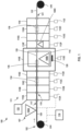
- FIG. 1 is a schematic diagram illustrating an example system 100 for continuous vacuum processing of a fiber tow 120.
- System 100 includes fiber system 102, sealing system 107, vacuum system 111, and controller 116.
- Fiber system 102 is configured to pass carbon fiber tow 120 through vacuum system 111. Although illustrated as a single carbon fiber tow 120, fiber system 102 may be configured to pass multiple carbon fiber tows, and may include multiples of any of the elements of fiber system 102.
- Fiber system 102 includes starter core 104 and winding core 106. Starter core 104 and/or winding core 106 may be coupled to a tensioner (not shown), for example, an electric motor or a braking system configured to provide a selected tension on fiber tow 120 as core 104 is rotated to pass fiber tow 120 through vacuum system 111.
- a tensioner not shown
- an electric motor or a braking system configured to provide a selected tension on fiber tow 120 as core 104 is rotated to pass fiber tow 120 through vacuum system 111.
- Fiber system 102 may additionally or alternatively include one or more tensioning rollers (e.g., nip rollers, idlers, adjustable and/or translatable idlers, web steering rollers and the like) configured to provide a selected tension on fiber tow 120 (or a web material or removable backing material onto which fiber tow 120 is disposed) as starter core 104 is rotated to pass fiber tow 120 through vacuum system 111 (along the direction of the arrow in FIG. 1 ).
- the selected tension may affect a density of carbon fiber tow 120, e.g., a fiber volume and/or density relative to a total volume and/or density of fiber tow 120.
- fiber system 102 may be omitted from system 100, and carbon fiber tow may be loaded directly into vacuum system 100 before vacuum system 100 is closed.
- Fiber system 102 may be selectively controlled to control the feed rate of carbon fiber tow 120 through vacuum system 111, such that the dwell time of carbon fiber tow 120 in vacuum system 111 may be controlled.
- a thickness of a coating of sealing material applied by sealing system 107, or an infiltration distance of material applied by sealing system 107 e.g., a metal material such as a material including silicon
- System 100 includes vacuum system 111.
- vacuum system 111 is configured to continuously vacuum process fiber tow 120 and includes a plurality of vacuum chambers.
- vacuum system 111 may include a single vacuum chamber.
- Vacuum system 111 includes plurality of vacuum chambers 110A, 110B, 110C, 110D, 110E, 110F, 110G, 110H, and 110I (collectively "vacuum chambers 110"). Vacuum system 111 also includes one or more vacuum pumps configured to evacuate vacuum chambers 110. In some examples, vacuum system 111 may include a plurality of vacuum pumps 112A, 112B, 112C, 112D, 112E, 112F, 112G, 112H, and 112I (collectively "vacuum pumps 112") As such, vacuum system 111 may include a corresponding vacuum pump 112A for each vacuum chamber 110A of the plurality of vacuum chambers 110.
- vacuum chamber may take on any other suitable shape.
- vacuum chambers 110 may be sections of tube surrounding fiber tow 120.
- tube-shaped vacuum chambers 110 may substantially reduce the volume that must be evacuated by vacuum pumps 112.
- Vacuum chambers 110 may be arranged in series, such that fiber tow 120 is configured to pass through first inlet 117 into first vacuum chamber 110A, through first vacuum chamber outlet 119 and into second vacuum chamber 110B, and so on until fiber tow 120 passes out of last vacuum chamber 110I through outlet 121.
- Inlet 117 and outlet 119 may be defined in a wall of vacuum chamber 110A, as shown.
- first vacuum chamber 110A and second vacuum chamber 110B may share a wall, such that first vacuum chamber outlet 119 also defines an inlet to second vacuum chamber 119B.
- each vacuum chamber 110A-110I may be a separate, discrete chamber with its own inlet and outlet connected with a tube.
- the aperture in the wall of 110A may be defined to reduce leakage of the atmosphere exterior to vacuum system 111 into vacuum system 111.
- a diameter of inlet 117 and/or outlet 119 may be similar to a diameter of carbon fiber tow 120, such that there is a tight tolerance or contact between carbon fiber tow 120 and inlet 117, outlet 119, or both, so that leakage is reduced.
- inlet 117 and/or outlet 119 may extend along a length of carbon fiber tow 120, and may in some examples define a tortuous path along the length of carbon fiber tow 120, which may further reduce leakage.
- system 100 may include sealing system 107, which may be configured to reduce leakage of atmosphere into vacuum system 111 by applying a layer of sealing material to carbon fiber tow 120, as will be further described below.
- vacuum system 111 may include up to 20 vacuum chambers 110.
- central vacuum chamber 110E is illustrated as being in the middle of the series of vacuum chambers 110 such that fiber tow 120 is configured to pass through four chambers before entering central vacuum chamber 110E and four chambers after exiting central vacuum chamber 110E, central vacuum chamber 110E need not be located exactly in the middle of vacuum system 111.
- more vacuum chambers 110 may be disposed before central vacuum chamber 110E, or more vacuum chambers 110 may be disposed after central vacuum chamber 110E.
- At least two vacuum chambers 110A, 110B of vacuum chambers 110 may be configured to operate at a different level of vacuum pressure from each other during vacuum processing of fiber tow 120.
- first set of vacuum chambers 110A-110D may be configured to step down (e.g., reduce) a pressure from an atmospheric pressure (e.g., about 760 torr) outside of vacuum system to an operating pressure for a vacuum processing operation inside central vacuum chamber 110E.
- central vacuum chamber 110E may be configured to operate at less than, for example, about 500 millitorr, or about 250 millitorr.
- first vacuum chamber 110A may be configured to operate at about 50 torr
- second vacuum chamber 110B may be configured to operate at about 25 torr
- third vacuum chamber 110C may be configured to operate at about 10 torr
- fourth vacuum chamber 110D may be configured to operate at about 1 torr.
- vacuum pumps 112 may be similar to each other.
- vacuum pumps 112 may be standard vacuum pumps, which may be relatively widely available and inexpensive, because the work required to reach the threshold vacuum level for the vacuum process in central vacuum chamber 110E may be shared across multiple vacuum pumps 112A-112E.
- Vacuum system 111 includes second set of vacuum chambers 110F-110I.
- Vacuum chambers 110F-110I may be configured to step up (e.g., increase) a pressure from the operating pressure for a vacuum processing operation inside central vacuum chamber 110E (e.g., about 500 millitorr) to the atmospheric pressure (e.g., about 760 torr) outside of vacuum system 111, in a manner similar to and opposite the operation of first set of vacuum chambers 110A-110D.
- vacuum chamber 110F may be configured to operate at about 1 torr
- vacuum chamber 110G may be configured to operate at about 10 torr
- vacuum chamber 110H may be configured to operate at about 25 torr
- vacuum chamber 110I may be configured to operate at about 50 torr. Absent second set of vacuum chambers 110F-110I, the external atmosphere beyond vacuum system 111 may leak directly into central vacuum chamber 110E, which would prevent central chamber 110E from reaching the threshold vacuum level for vacuum processing.
- central vacuum chamber 110E may include an objective chamber 114.
- Objective chamber 114 may, in some examples, be a retort configured to be placed in a vacuum furnace, and central vacuum chamber 110E may be a vacuum furnace configured to house objective chamber 114.
- vacuum chamber 110E may be configured to serve the dual purpose of acting as an objective chamber. In other words, objective chamber 114 need not be a separate component of vacuum system 111.
- central vacuum chamber 110E may be configured to be a CVI and/or CVD chamber, or slurry burnout chamber, as will be further described below.
- objective chamber 114 may be configured to chemically react portion 126 of fiber tow 120 disposed within objective chamber 114 to convert carbon fiber tow 120 to reacted fiber tow 122.
- carbon fiber tow 120 be converted within objective chamber 114, and may exit objective chamber 114 with at least part of carbon fiber tow 120 having a different chemical composition than it did when entering objective chamber 114.
- carbon fiber tow 120 may become reacted fiber tow 122, indicated by the color change and reference number change in FIG. 1 .
- fiber system 102 may be configured to replace portion 126 with a new portion of fiber tow 120
- objective chamber 114 may be configured to continuously react carbon fiber tow 120 to form reacted fiber tow 122, which may include metal carbide.
- one or more of the plurality of vacuum chambers 110 may be configured to heat carbon fiber tow 120 during a continuous vacuum process.
- central vacuum chamber 114 may include one or more heating elements 128.
- Heating element(s) 128 may be include any suitable means for heating, such as an electrical element, a gas heating element, or the like.
- Heating element(s) 128 may be configured to heat central vacuum chamber 110E to a temperature suitable for the vacuum process, such as a temperature for chemical vapor infiltration/ chemical vapor deposition.
- objective chamber 114 may be heated to a temperature of at least about 1400 degrees Celsius.
- System 100 also includes sealing system 107.
- Sealing system 107 may be configured to apply a sealing material (not illustrated) to fiber tow 120.
- the sealing material may be configured to reduce leakage of external atmosphere into one or more vacuum chambers 110, such as central vacuum chamber.
- Sealing system may includes one or more deposition members 108A, 108B, 108C (collectively "deposition members 108") configured to apply a layer of sealing material to carbon fiber tow 120.
- a layer of sealing material may be applied be deposition member 108A before fiber tow 120 enters first vacuum chamber 110A.
- the sealing material may assist in forming a seal between fiber tow 120 and the wall of vacuum chamber 110A as fiber tow 120 passes through inlet 117.
- the sealing material may include any material or mixture of materials that assists in reducing leakage of the external environment into vacuum chamber 110A.
- water, lubricants such as vacuum grease, or other sealants may be applied to carbon fiber tow 120 by deposition member 108A.
- Deposition members 108 may apply the sealant via a spray, such as by one or more spray nozzles. Additionally, or alternatively, deposition members may include a brush system or a bath system configured to apply a layer of sealant material.
- sealing system may include additional deposition member 108B, 108C configured to apply or additional layers of sealing material.
- each of vacuum chambers 110 may include a corresponding deposition member 108 configured to apply a layer of sealing material configured to reduce leakage into the next vacuum chamber in the sequence.
- system 100 may include a metal application system.
- sealing system 107 is configured to act as the metal application system, but a separate metal application system may be included in some examples.
- deposition member 108A and/or deposition member 108B may be configured to apply a metal slurry to fiber tow 120.
- the metal slurry may be configured to act as a sealing layer surrounding from deposition member 108A to objective chamber 114, which may be at a low enough pressure and high enough pressure to vaporize the metal slurry for vapor deposition and/or infiltration of portion 126 of carbon fiber tow 120 disposed within objective chamber 114.
- Deposition member 108C may then apply a sealing material such as vacuum grease or sealing through second set of vacuum chambers 110F-110I.
- the sealing material may be a metal slurry configured to react (e.g., chemically react) with carbon fiber tow 120 to generate reacted fiber tow 122, which may include or consist of metal carbide.
- the metal application system may include deposition member 108B, which may be disposed within objective chamber 114.
- deposition member 108B may be configured to apply metal to carbon fiber tow 120 from a vapor.
- deposition member 108B may be a silicon boat or silicon ingot which is configured to vaporize in the environment of objective chamber 114 and vapor deposit on carbon fiber tow 120.
- At least one vacuum chamber 110A system 100 may include an inert gas inlet (not called out with a reference numeral for clarity) configured to receive inert gas (e.g., argon) from an inert gas supply 132.
- inert gas e.g., argon
- Outfitting first vacuum chamber 110A with an inert gas may advantageously assist in vacuum processing fiber tow 120, because leakage into successive vacuum chambers 110 may be of the inert gas that does not interfere with the vacuum process as much as gases from the external atmosphere.
- system 100 may also include controller 116.
- Controller 116 may include, for example, a computing device, a desktop computer, a laptop computer, a workstation, a server, a mainframe, a cloud computing system, a tablet, a smart phone, or the like. Controller 116 may be configured to control operation of system 100, including, for example, the power supplied to fiber system 102, vacuum system 111, and/or sealing system 107. As such, the speed of fiber tow 120 and thus the dwell time of fiber tow 120 in vacuum system 111 may be selectively configured for desired vacuum processing.
- Controller 116 may be communicatively coupled to the various component of system 100 including, e.g., starter core 104, vacuum pump 112A, deposition member 108A, and/or the like using respective communication connections. Only a portion of these connections may be illustrated in FIG. 1 for clarity.
- the communication connections may include network links, such as Ethernet, ATM, or other network connections. Such connections may be wireless and/or wired connections.
- the communication connections may include other types of device connections, such as USB, IEEE 1394, or the like.
- controller 116 may include control circuitry, such as one or more processors, including one or more microprocessors, digital signal processors (DSPs), application specific integrated circuits (ASICs), field programmable gate arrays (FPGAs), or any other equivalent integrated or discrete logic circuitry, as well as any combinations of such components.
- processors including one or more microprocessors, digital signal processors (DSPs), application specific integrated circuits (ASICs), field programmable gate arrays (FPGAs), or any other equivalent integrated or discrete logic circuitry, as well as any combinations of such components.
- DSPs digital signal processors
- ASICs application specific integrated circuits
- FPGAs field programmable gate arrays
- Carbon fiber tow 120 may be any suitable fiber tow suitable for vacuum processing.
- carbon fiber tow 120 may be a bundle of individual fibers linearly aligned.
- fiber 120 may include a plurality of continuous filaments.
- Each tow may include about 10 to about 10,000 individual fibers unidirectionally aligned to form a single tow.
- the individual fibers in the tow may define an individual fiber diameter.
- the individual fiber diameter may be in a range of from about 0.1 micrometers to about 100 micrometers.
- carbon fiber tow 120 may include carbon or may consist essentially of carbon.
- some or all of the individual fibers in fiber tow 120 may include carbon.
- Carbon fiber tows may be made using any suitable technique. Additionally, or alternatively, the individual fibers in fiber tow 120 may include other materials, which may be coated or reacted with any suitable coating or reaction material, such as a metal, an oxide, a nitride, or the like.
- one or more deposition members 108A, 108B of sealant system 107 may be configured to apply a metal slurry.
- system 100 may be configured to generate a fiber tow comprising a metal carbide, because the metal slurry may infiltrate and react with carbon of carbon fiber tow 120.
- FIGS. 2-4 illustrate portions of fiber tow 120 at various points throughout the process of conversion of carbon fiber tow 120 from a carbon fiber tow to a fiber tow comprising metal carbide.
- FIGS. 2-4 illustrate portions of carbon fiber tow 120 within windows 134, 136, and 138 of FIG. 1 , respectively.
- FIG. 2 is a schematic cross-sectional diagram illustrating the portion of carbon fiber tow 120 within window 134 of FIG. 1 .
- Carbon fiber tow 120 is covered in layer 130 of sealant material, which in this example is a metal slurry, such as silicon slurry.
- the slurry may include a metal (e.g., silicon) and one or more carriers configured to maintain the proximity of the metal and the surface of fiber tow 120.
- system 100 may be used to generate fiber tows comprising or consisting of metal carbide even where only deposition member 108B is configured to apply a layer of metal to fiber tow 120 in vapor form.
- carbon fiber tow 120 may include a surface portion (e.g., outer-most 10-25 microns) that includes carbon filaments capable of reacting with the metal to form a metal carbide.
- the carbon filaments of the surface portion may have a particular composition and/or morphology, such as microstructure, phase composition, geometry of component phases, morphology of components phases, and/or dimensions and distribution of ceramic fibers or pores, crystal structure, presence and type of impurities, particle morphology shape and size, crystal surface terminations (e.g., active facets), crystal defects, and/or surface functionalization.
- This particular composition and/or morphology may result in a reaction with the metal according to particular reaction thermodynamics and kinetics, such as a temperature of reaction and a rate of reaction.
- the portion of fiber tow 120 within window 136 which is located within objective chamber 114, as illustrated.
- the metal the metal of the metal slurry of layer 130 may react with carbon of carbon of carbon fiber tow 120 to form metal carbide 140.
- the environment inside objective chamber 114 may be at a low enough pressure and high enough temperature such that the metal may melt and/or vaporize.
- Objective chamber 114 may maintain a vapor pressure of the metal at the surface of carbon fiber tow 120 in stoichiometric excess.
- a variety of parameters may be controlled to encourage migration of the metal into, and reaction with, carbon of carbon fiber tow 120.
- the metal is silicon.
- the temperature of objective chamber 114 may be maintained at greater than about 1400°C
- the pressure may be maintained at less than about 500 millitorr
- the dwell time of any individual portion of fiber tow 120 within objective chamber 114 may be between on the order of seconds to minutes.
- this reaction may be limited by diffusion of the metal into fiber tow 120.
- the newly formed metal carbide may form a diffusion barrier separating the reactants (e.g., carbon and metal), which may stop the thickening and further creation to form thicker metal carbides (e.g., by preventing metal from further penetrating into a depth of the surface portion of carbon fiber tow 120 and/or preventing diffusion of carbon out of carbon fiber tow 120 to react with the metal).
- FIG. 4 is a schematic cross-sectional diagram illustrating the example portion of carbon fiber tow 120 within window 138 of FIG. 1 .
- a diameter of the fiber tow may correspond to a size for which the metal may infiltrate and react (e.g., less than a diffusion limit), such as less than about 50 micrometers ( ⁇ m), or between about 10 ⁇ m and about 50 ⁇ m.
- carbon fiber tow 120 may be completely converted to reacted fiber tow 122, which may consist of or consist essentially of metal carbide 140. In some examples, any remaining metal or carrier on fiber tow 120 may be removed, such as through evaporation.
- the resulting reacted fiber tow 122 may be a relatively homogeneous metal carbide having a relatively uniform thickness.
- system 100 may be configured to generate a reacted fiber tow 122 comprising a metal carbide.
- Reacted fiber tow 122 may be stable at temperatures of up to about 3600°F (about 2000°C).
- stable may mean that reacted fiber tow 122 does not degrade into its constituent elements, does not react with carbon, and/or does not react with other elements or compounds present in the environment in reacted fiber tow 122 is eventually used, for example in aerospace applications.
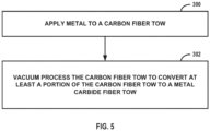
- FIG. 5 is a flowchart illustrating an example technique for generating a fiber tow which includes metal carbide. Although described with respect to system 100 of FIG. 1 , the illustrated technique may be performed by other systems, and system 100 may be used to perform other techniques.
- the technique of FIG. 5 includes applying metal to carbon fiber tow 120 (200).
- the metal may be applied via sealant system 107 as part of sealant material layer 130, or may be applied separately by a separate metal application system.
- the metal may be silicon, and applying silicon to carbon fiber tow 120 may include depositing silicon on carbon fiber tow 120 from a vapor.
- applying metal to carbon fiber tow 120 includes applying a layer 130 which includes a metal slurry (e.g., silicon slurry) onto carbon fiber tow 120.
- the technique of FIG. 5 also includes vacuum processing carbon fiber tow 120 to convert at least a part of portion 126 of carbon fiber tow 120 to metal carbide.
- metal may be silicon, titanium, tungsten, combinations thereof, or other metals.
- the technique of FIG. 5 also includes heating carbon fiber tow 120 via one or more heating elements 128. Heating the carbon fiber tow may include raising the temperature of carbon fiber tow 120 to a temperature of at least about 1400 degrees Celsius.
- the technique of FIG. 5 may include continuously vacuum processing carbon fiber tow 120 by passing carbon fiber tow 120 through a plurality of vacuum chambers 110.
- vacuum chambers 110 may be arranged in series.
- the technique of FIG. 5 may include passing carbon fiber tow 120 through central vacuum chamber 110E, which may be operated at the lowest pressure of vacuum chambers 110.
- Central vacuum chamber 110E may include objective chamber 114, which may be separate from (e.g., inside) or the same as central vacuum chamber 110E. Converting at least a portion of carbon fiber tow 120 to a reacted fiber tow 122 may occur in objective chamber 114.
- carbon fiber tow 120 may be completely converted into a silicon carbide reacted fiber tow 122, as shown in FIG. 4 .
- Carbon fiber tow 120 may include from about 10 to about 10,000 individual carbon fibers.
- Carbon fiber tow 120 includes a cross-sectional fiber diameter of from about 10 micrometers to about 50 micrometers.
- a carbon fiber tow was vacuum processed using techniques according to the present disclosure to generate a silicon carbide fiber tow.
- a carbon fiber tow was coated with a layer of silicon slurry and placed in a vacuum chamber.
- the vacuum chamber was heated by a heating element to about 1400 degrees Celsius and operated a pressure of about 500 millitorr.
- the carbon fiber was completely converted to a silicon carbide fiber.
- the dwell time was on the order of 30 minutes, however it is expected that complete conversion of the carbon fiber tow to metal carbide could be completed within about 5 minutes, or about 10 minutes.
- FIGS. 6A and 6B are micrographs illustrating a portion of reacted fiber tow 222, generated with a vacuum process according to the present disclosure.
- FIG. 6B is a closeup of the same reacted fiber tow illustrated in FIG. 6A .
- the illustrated reacted fiber tow 222 began as a carbon fiber tow, but was treated under vacuum as described herein.
- the carbon fiber tow was completely converted to silicon carbide 240.
Landscapes
- Chemical & Material Sciences (AREA)
- Engineering & Computer Science (AREA)
- Ceramic Engineering (AREA)
- Manufacturing & Machinery (AREA)
- Materials Engineering (AREA)
- Organic Chemistry (AREA)
- Structural Engineering (AREA)
- Inorganic Chemistry (AREA)
- Physics & Mathematics (AREA)
- Thermal Sciences (AREA)
- Nanotechnology (AREA)
- Chemical Kinetics & Catalysis (AREA)
- General Chemical & Material Sciences (AREA)
- Chemical Or Physical Treatment Of Fibers (AREA)
Abstract
Description
- The disclosure relates to vacuum processing of fibers.
- Ceramic fibers may be embedded in a matrix to create a ceramic matrix composite (CMC). CMCs may be used in high temperature applications. For example, CMC components may be used as friction materials for commercial and military aircraft, or in refractory applications. Next generation ceramic fibers, such as metal carbide fibers, may be desirable for improved material properties, such as increased temperature resistance and/or increased oxidation resistance. However, these ceramic fibers may be difficult and expensive to make, limiting the applications where they may be employed.
- In some examples, the disclosure is directed to a technique for generating a fiber tow comprising metal carbide. Generating the fiber tow comprising metal carbide includes applying metal to a carbon fiber tow. The technique also includes vacuum processing the carbon fiber tow to convert at least a portion of the carbon fiber tow to metal carbide.
- In some examples, the disclosure is directed to a system for generating a fiber tow comprising metal carbide. The system includes a metal application system configured to apply metal to a carbon fiber tow. The system also includes a vacuum processing system configured to convert at least a portion of a carbon fiber tow to a metal carbide.
- The details of one or more examples of the disclosure are set forth in the accompanying drawings and the description below. Other features, objects, and advantages of the disclosure will be apparent from the description and drawings, and from the claims.
-
-
FIG. 1 is a schematic diagram illustrating an example system for generating a metal carbide fiber tow according to some examples of the present disclosure. -
FIG. 2 is a schematic cross-sectional diagram illustrating a portion of the fiber tow ofFIG. 1 covered in a layer of sealant material according to some examples of the present disclosure. -
FIG. 3 is a schematic cross-sectional diagram illustrating a portion of the example carbon fiber tow ofFIG. 1 partially converted to metal carbide. -
FIG. 4 is a schematic cross-sectional diagram illustrating a portion of the example carbon fiber tow ofFIG. 1 completely converted to metal carbide. -
FIG. 5 is a flowchart illustrating an example technique for generating a metal carbide fiber tow according to some examples of the present disclosure. -
FIGS. 6A and 6B illustrate an example metal carbide fiber tow generated by vacuum processing techniques according to the present disclosure. - The disclosure describes systems and techniques for generating metal carbide fiber tows. Carbon fiber tows, for example, may be coated or converted (e.g., chemically reacted) to form metal carbide coated carbon fiber tows or metal carbide fiber tows. Metal carbide fiber tows, such as silicon carbide fiber tows, may have one or more desirable properties relative to carbon fibers (e.g., increased strength, increased oxidation resistance, or the like). The disclosed techniques and systems for generating metal carbide fiber tows may advantageously allow for these fiber tows to be used in more applications because they may be made more economically.
- The disclosure describes vacuum processing of carbon fiber tows to generate a fiber tow that comprises or consists of metal carbide. The vacuum process may be a batch process or a continuous process. In a batch process, a discrete number and length of carbon fiber tows are treated (e.g., by a chemical vapor infiltration (CVI) process, a chemical vapor deposition (CVD) process, a slurry deposition process, or the like) under vacuum. The carbon fiber tows may be any suitable carbon fiber tows arranged in any suitable arrangement. For example, tows of fibers may be arranged in a linear, radial, or chordal arrangement. The carbon fiber tows may be relatively short, chopped and/or entangled fibers. In some examples, the carbon fiber tows may be wrapped around mandrels or bobbins in a spool. Alternatively, as will be described below, the fiber tow may be a continuous carbon fiber tow that is continuously vacuum processed to at least partially convert the carbon fiber tow to a reacted fiber tow that includes metal carbide.
- In some examples, vacuum processing of carbon fiber tows according to the present disclosure may include passing a carbon fiber tow through a plurality of vacuum chambers that are arranged in series. In some examples, each vacuum chamber of the plurality of vacuum chambers may be outfitted with a corresponding vacuum pump of a plurality of vacuum pumps. The plurality of vacuum chambers may be configured to step down (e.g., reduce) the pressure at each successive vacuum chamber, until a portion of the carbon fiber tow passes into a central vacuum chamber.
- The central vacuum chamber may, in some examples, consist of or include a objective chamber configured to coat or convert the portion of the fiber tow inside the central vacuum chamber. The operating pressure in the central vacuum chamber may be the lowest pressure (i.e., highest vacuum level) of the plurality of vacuum chambers. Although described herein as a central vacuum chamber, the central vacuum chamber need not be precisely the middle vacuum chamber of the plurality of chambers. Upon reaching the central vacuum chamber, the fiber tow may be coated or converted (e.g., partially converted or completely converted) to a fiber tow that includes metal carbide.
- Next, the fiber tow may pass through a second set of vacuum chambers configured to step up (e.g., increase) the pressure at each successive vacuum chamber until the fiber tow exits the vacuum system. In this way, a carbon fiber tow may be continuously processed under vacuum because the pressure in the central vacuum chamber may be maintained below an acceptable threshold level for the conversion to metal carbide by the plurality of vacuum chambers on either side of the central vacuum chamber. Advantageously, the plurality of vacuum chambers may substantially prevent or minimize entry of an atmosphere external to the vacuum system from reaching the central vacuum chamber. Thus, even though continuous vacuum processing of a fiber tow may involve passing the fiber tow through an inlet to the vacuum system and an outlet of the vacuum system, the plurality of vacuum chambers, arranged both before and after the central vacuum chamber, may provide for an acceptable vacuum level for vacuum processing in the central vacuum chamber.
- Although described primarily herein as a single carbon fiber tow, other numbers of carbon fiber tows are considered suitable for use in systems and techniques described herein. For example, two, three, four, or more discrete carbon fiber tows may be vacuum processed simultaneously. Although described below primarily as a carbon fiber being vacuum processed to convert to a metal carbide fiber, other materials are considered for the disclosed vacuum processing systems and techniques. Other fibers suitable for vacuum processing treatment by CVI, CVD or other processes may also be treated in the disclosed systems.
- As mentioned above, in some examples of the present disclosure, carbon fiber tows may be treated to generate fiber tows including metal carbide. Surprisingly, in some examples, the carbon fiber tow may be completely converted to a metal carbide fiber tow, such as a silicon carbide fiber tow. Stated similarly, the fiber tow resulting from vacuum processing according to the present disclosure may consist of or consist essentially of metal carbide. This result may be surprising because complete conversion of a carbon fiber tow to a metal carbide fiber tow may be performed at a pressure level in the central vacuum chamber of less than about 500 millitorr.
- Metal carbide fiber tows may have desirable properties over carbon fiber tows, for example in aerospace applications, such as ultra-high temperature (e.g., greater than 1500 degrees Celsius (°C)) applications. However, metal carbide fiber tows have found only limited use since processes used to generate the fiber tows have limited the applications where it is cost-effective to use metal carbide fiber tows. For example, one way to make metal carbide fiber tows such as silicon carbide fiber tows involves pre-ceramic polymers which have complex and long processing cycles. Using vacuum processing systems and techniques disclosed herein may allow for the proliferation of these desirable materials because the continuous vacuum processing techniques may be cost-effective in more applications
- Although described herein primarily with respect to silicon as the metal in the metal carbide fiber tow, other suitable metals may be used, such as titanium, tungsten, or some other such metal.
-
FIG. 1 is a schematic diagram illustrating anexample system 100 for continuous vacuum processing of afiber tow 120.System 100 includesfiber system 102,sealing system 107,vacuum system 111, andcontroller 116. -
Fiber system 102 is configured to passcarbon fiber tow 120 throughvacuum system 111. Although illustrated as a singlecarbon fiber tow 120,fiber system 102 may be configured to pass multiple carbon fiber tows, and may include multiples of any of the elements offiber system 102.Fiber system 102 includesstarter core 104 and windingcore 106.Starter core 104 and/or windingcore 106 may be coupled to a tensioner (not shown), for example, an electric motor or a braking system configured to provide a selected tension onfiber tow 120 ascore 104 is rotated to passfiber tow 120 throughvacuum system 111.Fiber system 102 may additionally or alternatively include one or more tensioning rollers (e.g., nip rollers, idlers, adjustable and/or translatable idlers, web steering rollers and the like) configured to provide a selected tension on fiber tow 120 (or a web material or removable backing material onto whichfiber tow 120 is disposed) asstarter core 104 is rotated to passfiber tow 120 through vacuum system 111 (along the direction of the arrow inFIG. 1 ). In some examples, the selected tension may affect a density ofcarbon fiber tow 120, e.g., a fiber volume and/or density relative to a total volume and/or density offiber tow 120. In examples where metal carbide fiber tows are generated by a batch process,fiber system 102 may be omitted fromsystem 100, and carbon fiber tow may be loaded directly intovacuum system 100 beforevacuum system 100 is closed. -
Fiber system 102 may be selectively controlled to control the feed rate ofcarbon fiber tow 120 throughvacuum system 111, such that the dwell time ofcarbon fiber tow 120 invacuum system 111 may be controlled. In this way, a thickness of a coating of sealing material applied by sealingsystem 107, or an infiltration distance of material applied by sealing system 107 (e.g., a metal material such as a material including silicon) by controlling a length of dwell time in one or more vacuum chambers ofvacuum system 111. -
System 100 includesvacuum system 111. In the illustrated example,vacuum system 111 is configured to continuously vacuumprocess fiber tow 120 and includes a plurality of vacuum chambers. In alternative examples, wherecarbon fiber tow 120 is to be batch vacuum processed,vacuum system 111 may include a single vacuum chamber. -
Vacuum system 111 includes plurality ofvacuum chambers Vacuum system 111 also includes one or more vacuum pumps configured to evacuate vacuum chambers 110. In some examples,vacuum system 111 may include a plurality ofvacuum pumps vacuum system 111 may include acorresponding vacuum pump 112A for eachvacuum chamber 110A of the plurality of vacuum chambers 110. Although illustrated as defining a substantially rectangular cross-sectional area, vacuum chamber may take on any other suitable shape. For example, vacuum chambers 110 may be sections of tube surroundingfiber tow 120. Advantageously, tube-shaped vacuum chambers 110 may substantially reduce the volume that must be evacuated by vacuum pumps 112. - Vacuum chambers 110 may be arranged in series, such that
fiber tow 120 is configured to pass throughfirst inlet 117 intofirst vacuum chamber 110A, through firstvacuum chamber outlet 119 and intosecond vacuum chamber 110B, and so on untilfiber tow 120 passes out of last vacuum chamber 110I throughoutlet 121. Several vacuum chamber inlets and outlets are not specifically called out by reference numerals inFIG. 1 for clarity.Inlet 117 andoutlet 119 may be defined in a wall ofvacuum chamber 110A, as shown. In some examples, as illustrated,first vacuum chamber 110A andsecond vacuum chamber 110B may share a wall, such that firstvacuum chamber outlet 119 also defines an inlet to second vacuum chamber 119B. However, in some examples eachvacuum chamber 110A-110I may be a separate, discrete chamber with its own inlet and outlet connected with a tube. - The aperture in the wall of 110A may be defined to reduce leakage of the atmosphere exterior to
vacuum system 111 intovacuum system 111. For example, a diameter ofinlet 117 and/oroutlet 119 may be similar to a diameter ofcarbon fiber tow 120, such that there is a tight tolerance or contact betweencarbon fiber tow 120 andinlet 117,outlet 119, or both, so that leakage is reduced. Additionally, or alternatively,inlet 117 and/oroutlet 119 may extend along a length ofcarbon fiber tow 120, and may in some examples define a tortuous path along the length ofcarbon fiber tow 120, which may further reduce leakage. Additionally, or alternatively,system 100 may include sealingsystem 107, which may be configured to reduce leakage of atmosphere intovacuum system 111 by applying a layer of sealing material tocarbon fiber tow 120, as will be further described below. - Although the illustrated example of
FIG. 1 includes nine different vacuum chambers 110, any suitable number of vacuum chambers may be included in the plurality of vacuum chambers, for example a single vacuum chamber, or at least three vacuum chambers, or at least five vacuum chambers. In some examples,vacuum system 111 may include up to 20 vacuum chambers 110. Furthermore, althoughcentral vacuum chamber 110E is illustrated as being in the middle of the series of vacuum chambers 110 such thatfiber tow 120 is configured to pass through four chambers before enteringcentral vacuum chamber 110E and four chambers after exitingcentral vacuum chamber 110E,central vacuum chamber 110E need not be located exactly in the middle ofvacuum system 111. For example, more vacuum chambers 110 may be disposed beforecentral vacuum chamber 110E, or more vacuum chambers 110 may be disposed aftercentral vacuum chamber 110E. - At least two
vacuum chambers fiber tow 120. For example, first set ofvacuum chambers 110A-110D may be configured to step down (e.g., reduce) a pressure from an atmospheric pressure (e.g., about 760 torr) outside of vacuum system to an operating pressure for a vacuum processing operation insidecentral vacuum chamber 110E. For example,central vacuum chamber 110E may be configured to operate at less than, for example, about 500 millitorr, or about 250 millitorr. - To achieve this level of vacuum in
central vacuum chamber 110E,first vacuum chamber 110A may be configured to operate at about 50 torr,second vacuum chamber 110B may be configured to operate at about 25 torr,third vacuum chamber 110C may be configured to operate at about 10 torr, andfourth vacuum chamber 110D may be configured to operate at about 1 torr. It should be understood that these numbers are merely exemplary and not intended to be limiting. It should also be understood that as used herein, the term "about" to describe a value includes values within plus or minus 10% of the stated value. - Since the pressure may be reduced over the first set of
vacuum chambers 110A-110D, some minimal level of leakage resulting from the passage ofcarbon fiber tow 120 from the exterior atmosphere intofirst vacuum chamber 110A may be acceptable, because thesuccessive chambers 110B-110D may be configured to further reduce pressure. In some examples, vacuum pumps 112 may be similar to each other. Advantageously, vacuum pumps 112 may be standard vacuum pumps, which may be relatively widely available and inexpensive, because the work required to reach the threshold vacuum level for the vacuum process incentral vacuum chamber 110E may be shared acrossmultiple vacuum pumps 112A-112E. -
Vacuum system 111 includes second set ofvacuum chambers 110F-110I.Vacuum chambers 110F-110I may be configured to step up (e.g., increase) a pressure from the operating pressure for a vacuum processing operation insidecentral vacuum chamber 110E (e.g., about 500 millitorr) to the atmospheric pressure (e.g., about 760 torr) outside ofvacuum system 111, in a manner similar to and opposite the operation of first set ofvacuum chambers 110A-110D. For example,vacuum chamber 110F may be configured to operate at about 1 torr,vacuum chamber 110G may be configured to operate at about 10 torr,vacuum chamber 110H may be configured to operate at about 25 torr, and vacuum chamber 110I may be configured to operate at about 50 torr. Absent second set ofvacuum chambers 110F-110I, the external atmosphere beyondvacuum system 111 may leak directly intocentral vacuum chamber 110E, which would preventcentral chamber 110E from reaching the threshold vacuum level for vacuum processing. - In some examples,
central vacuum chamber 110E may include anobjective chamber 114.Objective chamber 114 may, in some examples, be a retort configured to be placed in a vacuum furnace, andcentral vacuum chamber 110E may be a vacuum furnace configured to houseobjective chamber 114. Alternatively,vacuum chamber 110E may be configured to serve the dual purpose of acting as an objective chamber. In other words,objective chamber 114 need not be a separate component ofvacuum system 111. In some examples,central vacuum chamber 110E may be configured to be a CVI and/or CVD chamber, or slurry burnout chamber, as will be further described below. - In some examples,
objective chamber 114 may be configured to chemically reactportion 126 offiber tow 120 disposed withinobjective chamber 114 to convertcarbon fiber tow 120 to reactedfiber tow 122. As such,carbon fiber tow 120 be converted withinobjective chamber 114, and may exitobjective chamber 114 with at least part ofcarbon fiber tow 120 having a different chemical composition than it did when enteringobjective chamber 114. Thus,carbon fiber tow 120 may become reactedfiber tow 122, indicated by the color change and reference number change inFIG. 1 . Sincefiber system 102 may be configured to replaceportion 126 with a new portion offiber tow 120,objective chamber 114 may be configured to continuously reactcarbon fiber tow 120 to form reactedfiber tow 122, which may include metal carbide. - In some examples, one or more of the plurality of vacuum chambers 110 may be configured to heat
carbon fiber tow 120 during a continuous vacuum process. For example,central vacuum chamber 114 may include one ormore heating elements 128. Heating element(s) 128 may be include any suitable means for heating, such as an electrical element, a gas heating element, or the like. Heating element(s) 128 may be configured to heatcentral vacuum chamber 110E to a temperature suitable for the vacuum process, such as a temperature for chemical vapor infiltration/ chemical vapor deposition. As such,objective chamber 114 may be heated to a temperature of at least about 1400 degrees Celsius. -
System 100 also includes sealingsystem 107.Sealing system 107 may be configured to apply a sealing material (not illustrated) tofiber tow 120. The sealing material may be configured to reduce leakage of external atmosphere into one or more vacuum chambers 110, such as central vacuum chamber. Sealing system may includes one ormore deposition members carbon fiber tow 120. For example, a layer of sealing material may be applied bedeposition member 108A beforefiber tow 120 entersfirst vacuum chamber 110A. The sealing material may assist in forming a seal betweenfiber tow 120 and the wall ofvacuum chamber 110A asfiber tow 120 passes throughinlet 117. The sealing material may include any material or mixture of materials that assists in reducing leakage of the external environment intovacuum chamber 110A. For example, water, lubricants such as vacuum grease, or other sealants may be applied tocarbon fiber tow 120 bydeposition member 108A. Deposition members 108 may apply the sealant via a spray, such as by one or more spray nozzles. Additionally, or alternatively, deposition members may include a brush system or a bath system configured to apply a layer of sealant material. - In some examples, the applied layer sealing material may evaporate in the reduced pressure environment inside
vacuum chamber 110A. Accordingly, sealing system may includeadditional deposition member - In some examples,
system 100 may include a metal application system. In the illustrated example ofFIG. 1 , sealingsystem 107 is configured to act as the metal application system, but a separate metal application system may be included in some examples. In the illustrated example ofFIG. 1 ,deposition member 108A and/ordeposition member 108B may be configured to apply a metal slurry tofiber tow 120. The metal slurry may be configured to act as a sealing layer surrounding fromdeposition member 108A toobjective chamber 114, which may be at a low enough pressure and high enough pressure to vaporize the metal slurry for vapor deposition and/or infiltration ofportion 126 ofcarbon fiber tow 120 disposed withinobjective chamber 114.Deposition member 108C may then apply a sealing material such as vacuum grease or sealing through second set ofvacuum chambers 110F-110I. In some examples, the sealing material may be a metal slurry configured to react (e.g., chemically react) withcarbon fiber tow 120 to generate reactedfiber tow 122, which may include or consist of metal carbide. - In some examples, the metal application system may include
deposition member 108B, which may be disposed withinobjective chamber 114. In some examples,deposition member 108B may be configured to apply metal tocarbon fiber tow 120 from a vapor. For instance,deposition member 108B may be a silicon boat or silicon ingot which is configured to vaporize in the environment ofobjective chamber 114 and vapor deposit oncarbon fiber tow 120. - In some examples, at least one
vacuum 100 may include an inert gas inlet (not called out with a reference numeral for clarity) configured to receive inert gas (e.g., argon) from anchamber 110A systeminert gas supply 132. Outfittingfirst vacuum chamber 110A with an inert gas, in some examples, may advantageously assist in vacuumprocessing fiber tow 120, because leakage into successive vacuum chambers 110 may be of the inert gas that does not interfere with the vacuum process as much as gases from the external atmosphere. - In some examples,
system 100 may also includecontroller 116.Controller 116 may include, for example, a computing device, a desktop computer, a laptop computer, a workstation, a server, a mainframe, a cloud computing system, a tablet, a smart phone, or the like.Controller 116 may be configured to control operation ofsystem 100, including, for example, the power supplied tofiber system 102,vacuum system 111, and/or sealingsystem 107. As such, the speed offiber tow 120 and thus the dwell time offiber tow 120 invacuum system 111 may be selectively configured for desired vacuum processing. Controller 116may be communicatively coupled to the various component ofsystem 100 including, e.g.,starter core 104,vacuum pump 112A,deposition member 108A, and/or the like using respective communication connections. Only a portion of these connections may be illustrated inFIG. 1 for clarity. In some examples, the communication connections may include network links, such as Ethernet, ATM, or other network connections. Such connections may be wireless and/or wired connections. In other examples, the communication connections may include other types of device connections, such as USB, IEEE 1394, or the like. In some examples,controller 116 may include control circuitry, such as one or more processors, including one or more microprocessors, digital signal processors (DSPs), application specific integrated circuits (ASICs), field programmable gate arrays (FPGAs), or any other equivalent integrated or discrete logic circuitry, as well as any combinations of such components. The term "processor" or "processing circuitry" may generally refer to any of the foregoing logic circuitry, alone or in combination with other logic circuitry, or any other equivalent circuitry. -
Carbon fiber tow 120 may be any suitable fiber tow suitable for vacuum processing. In some examples,carbon fiber tow 120 may be a bundle of individual fibers linearly aligned. As such,fiber 120 may include a plurality of continuous filaments. Each tow may include about 10 to about 10,000 individual fibers unidirectionally aligned to form a single tow. The individual fibers in the tow may define an individual fiber diameter. In some examples, the individual fiber diameter may be in a range of from about 0.1 micrometers to about 100 micrometers. In some examples,carbon fiber tow 120 may include carbon or may consist essentially of carbon. For example, some or all of the individual fibers infiber tow 120 may include carbon. Carbon fiber tows may be made using any suitable technique. Additionally, or alternatively, the individual fibers infiber tow 120 may include other materials, which may be coated or reacted with any suitable coating or reaction material, such as a metal, an oxide, a nitride, or the like. - In some examples, one or
more deposition members sealant system 107 may be configured to apply a metal slurry. In such examples,system 100 may be configured to generate a fiber tow comprising a metal carbide, because the metal slurry may infiltrate and react with carbon ofcarbon fiber tow 120.FIGS. 2-4 illustrate portions offiber tow 120 at various points throughout the process of conversion ofcarbon fiber tow 120 from a carbon fiber tow to a fiber tow comprising metal carbide.FIGS. 2-4 illustrate portions ofcarbon fiber tow 120 withinwindows FIG. 1 , respectively. -
FIG. 2 is a schematic cross-sectional diagram illustrating the portion ofcarbon fiber tow 120 withinwindow 134 ofFIG. 1 .Carbon fiber tow 120 is covered inlayer 130 of sealant material, which in this example is a metal slurry, such as silicon slurry. The slurry may include a metal (e.g., silicon) and one or more carriers configured to maintain the proximity of the metal and the surface offiber tow 120. It should be understood thatsystem 100 may be used to generate fiber tows comprising or consisting of metal carbide even whereonly deposition member 108B is configured to apply a layer of metal tofiber tow 120 in vapor form. - Prior to reaction with a metal,
carbon fiber tow 120 may include a surface portion (e.g., outer-most 10-25 microns) that includes carbon filaments capable of reacting with the metal to form a metal carbide. Without being limited to any particular theory, the carbon filaments of the surface portion may have a particular composition and/or morphology, such as microstructure, phase composition, geometry of component phases, morphology of components phases, and/or dimensions and distribution of ceramic fibers or pores, crystal structure, presence and type of impurities, particle morphology shape and size, crystal surface terminations (e.g., active facets), crystal defects, and/or surface functionalization. This particular composition and/or morphology may result in a reaction with the metal according to particular reaction thermodynamics and kinetics, such as a temperature of reaction and a rate of reaction. - Turning to
FIG. 3 , the portion offiber tow 120 withinwindow 136, which is located withinobjective chamber 114, as illustrated. Inobjective chamber 114, the metal the metal of the metal slurry oflayer 130 may react with carbon of carbon ofcarbon fiber tow 120 to formmetal carbide 140. The environment insideobjective chamber 114 may be at a low enough pressure and high enough temperature such that the metal may melt and/or vaporize.Objective chamber 114 may maintain a vapor pressure of the metal at the surface ofcarbon fiber tow 120 in stoichiometric excess. A variety of parameters, such as a temperature, a concentration (e.g., as indicated by pressure) of the metal nearcarbon fiber tow 120, and a dwell time withinobjective chamber 114, may be controlled to encourage migration of the metal into, and reaction with, carbon ofcarbon fiber tow 120. In the illustrated example, the metal is silicon. As such, the temperature ofobjective chamber 114 may be maintained at greater than about 1400°C, the pressure may be maintained at less than about 500 millitorr, and the dwell time of any individual portion offiber tow 120 withinobjective chamber 114 may be between on the order of seconds to minutes. - In some instances, this reaction may be limited by diffusion of the metal into
fiber tow 120. As the metal reacts with the individual fibers ofcarbon fiber tow 120, the newly formed metal carbide may form a diffusion barrier separating the reactants (e.g., carbon and metal), which may stop the thickening and further creation to form thicker metal carbides (e.g., by preventing metal from further penetrating into a depth of the surface portion ofcarbon fiber tow 120 and/or preventing diffusion of carbon out ofcarbon fiber tow 120 to react with the metal). -
FIG. 4 is a schematic cross-sectional diagram illustrating the example portion ofcarbon fiber tow 120 withinwindow 138 ofFIG. 1 . In this example, aftercarbon fiber tow 120 has exitedobjective chamber 114 ofcentral vacuum chamber 110E,carbon fiber tow 120 has been converted to reactedfiber tow 122. In the illustrated example ofFIG. 4 , a diameter of the fiber tow may correspond to a size for which the metal may infiltrate and react (e.g., less than a diffusion limit), such as less than about 50 micrometers (µm), or between about 10 µm and about 50 µm. Where the diameter of the fiber tow is less than the diffusion limit,carbon fiber tow 120 may be completely converted to reactedfiber tow 122, which may consist of or consist essentially ofmetal carbide 140. In some examples, any remaining metal or carrier onfiber tow 120 may be removed, such as through evaporation. The resulting reactedfiber tow 122 may be a relatively homogeneous metal carbide having a relatively uniform thickness. - As such,
system 100 may be configured to generate a reactedfiber tow 122 comprising a metal carbide. Reactedfiber tow 122 may be stable at temperatures of up to about 3600°F (about 2000°C). In this context, "stable" may mean that reactedfiber tow 122 does not degrade into its constituent elements, does not react with carbon, and/or does not react with other elements or compounds present in the environment in reactedfiber tow 122 is eventually used, for example in aerospace applications. -
FIG. 5 is a flowchart illustrating an example technique for generating a fiber tow which includes metal carbide. Although described with respect tosystem 100 ofFIG. 1 , the illustrated technique may be performed by other systems, andsystem 100 may be used to perform other techniques. - The technique of
FIG. 5 includes applying metal to carbon fiber tow 120 (200). The metal may be applied viasealant system 107 as part ofsealant material layer 130, or may be applied separately by a separate metal application system. In some examples, the metal may be silicon, and applying silicon tocarbon fiber tow 120 may include depositing silicon oncarbon fiber tow 120 from a vapor. In other examples applying metal tocarbon fiber tow 120 includes applying alayer 130 which includes a metal slurry (e.g., silicon slurry) ontocarbon fiber tow 120. - The technique of
FIG. 5 also includes vacuum processingcarbon fiber tow 120 to convert at least a part ofportion 126 ofcarbon fiber tow 120 to metal carbide. Although silicon is specifically mentioned above, in some examples the metal may be silicon, titanium, tungsten, combinations thereof, or other metals. - In some examples, the technique of
FIG. 5 also includes heatingcarbon fiber tow 120 via one ormore heating elements 128. Heating the carbon fiber tow may include raising the temperature ofcarbon fiber tow 120 to a temperature of at least about 1400 degrees Celsius. - In some examples, the technique of
FIG. 5 may include continuously vacuum processingcarbon fiber tow 120 by passingcarbon fiber tow 120 through a plurality of vacuum chambers 110. In some examples, vacuum chambers 110 may be arranged in series. The technique ofFIG. 5 may include passingcarbon fiber tow 120 throughcentral vacuum chamber 110E, which may be operated at the lowest pressure of vacuum chambers 110.Central vacuum chamber 110E may includeobjective chamber 114, which may be separate from (e.g., inside) or the same ascentral vacuum chamber 110E. Converting at least a portion ofcarbon fiber tow 120 to a reactedfiber tow 122 may occur inobjective chamber 114. - In some examples,
carbon fiber tow 120 may be completely converted into a silicon carbide reactedfiber tow 122, as shown inFIG. 4 .Carbon fiber tow 120 may include from about 10 to about 10,000 individual carbon fibers.Carbon fiber tow 120 includes a cross-sectional fiber diameter of from about 10 micrometers to about 50 micrometers. - In a first example, a carbon fiber tow was vacuum processed using techniques according to the present disclosure to generate a silicon carbide fiber tow. A carbon fiber tow was coated with a layer of silicon slurry and placed in a vacuum chamber. The vacuum chamber was heated by a heating element to about 1400 degrees Celsius and operated a pressure of about 500 millitorr. In the objective chamber, the carbon fiber was completely converted to a silicon carbide fiber. The dwell time was on the order of 30 minutes, however it is expected that complete conversion of the carbon fiber tow to metal carbide could be completed within about 5 minutes, or about 10 minutes.
-
FIGS. 6A and 6B are micrographs illustrating a portion of reactedfiber tow 222, generated with a vacuum process according to the present disclosure.FIG. 6B is a closeup of the same reacted fiber tow illustrated inFIG. 6A . The illustrated reactedfiber tow 222 began as a carbon fiber tow, but was treated under vacuum as described herein. The carbon fiber tow was completely converted tosilicon carbide 240. - Various examples have been described. These and other examples are within the scope of the following clauses and claims:
- Clause 1. A method comprising: generating a fiber tow comprising metal carbide, wherein generating the fiber tow comprising metal carbide includes: applying metal to a carbon fiber tow, and vacuum processing the carbon fiber tow to convert at least a portion of the carbon fiber tow to metal carbide.
- Clause 2. The method of clause 1, wherein the metal carbide is silicon carbide.
- Clause 3. The method of clause 1, wherein vacuum processing the carbon fiber tow further comprises heating the carbon fiber tow.
- Clause 4. The method of clause 3, wherein heating the carbon fiber tow further comprises heating the carbon fiber tow to a temperature of at least about 1400 degrees Celsius.
- Clause 5. The method of clause 1, wherein vacuum processing the carbon fiber tow comprises continuously vacuum processing the carbon fiber tow by passing the carbon fiber tow through a plurality of vacuum chambers.
- Clause 6. The method of clause 5, wherein the plurality of vacuum chambers are arranged in series, and wherein passing the carbon fiber tow through the plurality of vacuum chambers comprises passing the carbon fiber tow through a central vacuum chamber which is at the lowest pressure of the plurality of vacuum chambers.
- Clause 7. The method of clause 6, wherein the central vacuum chamber is a objective chamber, and wherein converting at least a portion of the carbon fiber tow to a metal carbide fiber tow occurs in the objective chamber.
- Clause 8. The method of any of clauses 1-7, wherein vacuum processing the carbon fiber tow completely converting the carbon fiber tow into a silicon carbide fiber tow.
- Clause 9. The method of any of clauses 1-8, wherein applying silicon to the carbon fiber tow comprises applying a layer of silicon slurry onto the carbon fiber tow.
- Clause 10. The method of any of clauses 1-9, wherein applying silicon to the carbon fiber tow comprises depositing silicon on the carbon fiber tow from a vapor.
- Clause 11. The method of any of clauses 1-10, wherein the carbon fiber tow comprises about 10 to about 10,000 individual carbon fibers.
- Clause 12. The method of any of clauses 1-11, wherein the carbon fiber tow comprises a cross-sectional fiber diameter of from about 10 micrometers to about 50 micrometers.
- Clause 13. A system for generating a fiber tow comprising metal carbide, the system comprising: a metal application system configured to apply metal to a carbon fiber tow; and a vacuum processing system configured to convert at least a portion of a carbon fiber tow to metal carbide.
- Clause 14. The system of clause 13, wherein the metal carbide is silicon carbide.
- Clause 15. The system of clause 13, further comprising a heating element configured to heat the carbon fiber tow.
- Clause 16. The system of clause 15, wherein the heating element is configured to heat the carbon fiber tow to a temperature of at least about 1400 degrees Celsius.
- Clause 17. The system of clause 13-16, wherein the vacuum processing system includes a plurality of vacuum chambers configured to continuously vacuum process the carbon fiber tow by passing the carbon fiber tow through the plurality of vacuum chambers.
- Clause 18. The system of clause 17, wherein the plurality of vacuum chambers are arranged in series, and the plurality of vacuum chambers are configured to pass the carbon fiber tow through a central vacuum chamber which is at the lowest pressure of the plurality of vacuum chambers.
- Clause 19. The system of clause 18, wherein the central vacuum chamber is a objective chamber, and wherein the objective chamber is configured to convert at least a portion of the carbon fiber tow to a metal carbide fiber tow.
- Clause 20. The system of any of clauses 13-19, wherein the metal application system comprises a slurry bath system of brush system configured to apply a layer of metal slurry onto the carbon fiber tow.
- Clause 21. The system of any of clauses 13-20, wherein the metal application system is configured to depositing silicon on the carbon fiber tow from a vapor.
- Clause 22. The system of any of clauses 13-21, further comprising the carbon fiber tow, wherein the carbon fiber tow comprises about 10 to about 10,000 individual carbon fibers.
- Clause 23. The system of any of clauses 13-22, further comprising the carbon fiber tow, wherein the carbon fiber tow comprises a cross-sectional fiber diameter of from about 10 micrometers to about 50 micrometers.
Claims (15)
- A system for generating a fiber tow comprising metal carbide, the system comprising:a metal application system configured to apply metal to a carbon fiber tow; anda vacuum processing system configured to convert at least a portion of a carbon fiber tow to metal carbide.
- The system of claim 1, wherein the metal carbide is silicon carbide.
- The system of any of claim 1 or claim 2, further comprising a heating element configured to heat the carbon fiber tow.
- The system of claim 3, wherein the heating element is configured to heat the carbon fiber tow to a temperature of at least about 1400 degrees Celsius.
- The system of any of claims 1-4, wherein the vacuum processing system includes a plurality of vacuum chambers configured to continuously vacuum process the carbon fiber tow by passing the carbon fiber tow through the plurality of vacuum chambers.
- The system of claim 5, wherein the plurality of vacuum chambers are arranged in series, and
the plurality of vacuum chambers are configured to pass the carbon fiber tow through a central vacuum chamber which is at the lowest pressure of the plurality of vacuum chambers. - The system of claim 6, wherein the central vacuum chamber is an objective chamber, and wherein the objective chamber is configured to convert at least a portion of the carbon fiber tow to a metal carbide fiber tow.
- The system of any of claims 1-7, wherein the metal application system comprises a slurry bath system of brush system configured to apply a layer of metal slurry onto the carbon fiber tow.
- The system of any of claims 1-8, wherein the metal application system is configured to deposit silicon on the carbon fiber tow from a vapor.
- The system of any of claims 1-9, further comprising the carbon fiber tow, wherein the carbon fiber tow comprises about 10 to about 10,000 individual carbon fibers.
- The system of any of claims 1-10, further comprising the carbon fiber tow, wherein the carbon fiber tow comprises a cross-sectional fiber diameter of from about 10 micrometers to about 50 micrometers.
- A method comprising:
generating a fiber tow comprising metal carbide, wherein generating the fiber tow comprising metal carbide includes:applying metal to a carbon fiber tow, andvacuum processing the carbon fiber tow to convert at least a portion of the carbon fiber tow to metal carbide. - The method of claim 12, wherein the metal carbide is silicon carbide.
- The method of claim 12 or claim 13, wherein vacuum processing the carbon fiber tow further comprises heating the carbon fiber tow.
- The method of claim 14, wherein heating the carbon fiber tow further comprises heating the carbon fiber tow to a temperature of at least about 1400 degrees Celsius.
Applications Claiming Priority (1)
| Application Number | Priority Date | Filing Date | Title |
|---|---|---|---|
| US18/153,871 US20240239713A1 (en) | 2023-01-12 | 2023-01-12 | Conversion of carbon fiber tows to metal carbide fiber tows |
Publications (1)
| Publication Number | Publication Date |
|---|---|
| EP4400486A1 true EP4400486A1 (en) | 2024-07-17 |
Family
ID=89224130
Family Applications (1)
| Application Number | Title | Priority Date | Filing Date |
|---|---|---|---|
| EP23217885.5A Pending EP4400486A1 (en) | 2023-01-12 | 2023-12-19 | Conversion of carbon fiber tows to metal carbide fiber tows |
Country Status (2)
| Country | Link |
|---|---|
| US (1) | US20240239713A1 (en) |
| EP (1) | EP4400486A1 (en) |
Citations (4)
| Publication number | Priority date | Publication date | Assignee | Title |
|---|---|---|---|---|
| EP0209320A1 (en) * | 1985-07-10 | 1987-01-21 | Hitachi, Ltd. | Fiber-reinforced ceramics |
| US5876659A (en) * | 1993-06-25 | 1999-03-02 | Hitachi, Ltd. | Process for producing fiber reinforced composite |
| EP1867619A2 (en) * | 2006-06-16 | 2007-12-19 | United Technologies Corporation | Coating a ceramic based felt |
| US20160265143A1 (en) * | 2014-02-18 | 2016-09-15 | Advanced Ceramic Fibers, Llc | Metal carbide fibers and methods for their manufacture |
Family Cites Families (2)
| Publication number | Priority date | Publication date | Assignee | Title |
|---|---|---|---|---|
| US5187021A (en) * | 1989-02-08 | 1993-02-16 | Diamond Fiber Composites, Inc. | Coated and whiskered fibers for use in composite materials |
| US20070099527A1 (en) * | 2005-11-01 | 2007-05-03 | General Electric Company | Method and reactor to coat fiber tows and article |
-
2023
- 2023-01-12 US US18/153,871 patent/US20240239713A1/en active Pending
- 2023-12-19 EP EP23217885.5A patent/EP4400486A1/en active Pending
Patent Citations (4)
| Publication number | Priority date | Publication date | Assignee | Title |
|---|---|---|---|---|
| EP0209320A1 (en) * | 1985-07-10 | 1987-01-21 | Hitachi, Ltd. | Fiber-reinforced ceramics |
| US5876659A (en) * | 1993-06-25 | 1999-03-02 | Hitachi, Ltd. | Process for producing fiber reinforced composite |
| EP1867619A2 (en) * | 2006-06-16 | 2007-12-19 | United Technologies Corporation | Coating a ceramic based felt |
| US20160265143A1 (en) * | 2014-02-18 | 2016-09-15 | Advanced Ceramic Fibers, Llc | Metal carbide fibers and methods for their manufacture |
Also Published As
| Publication number | Publication date |
|---|---|
| US20240239713A1 (en) | 2024-07-18 |
Similar Documents
| Publication | Publication Date | Title |
|---|---|---|
| CN107737932B (en) | A kind of integrated laser increasing material manufacturing method that titanium or titanium alloy constituency are strengthened | |
| US6482476B1 (en) | Low temperature plasma enhanced CVD ceramic coating process for metal, alloy and ceramic materials | |
| US20090252945A1 (en) | Method and apparatus for the coating and for the surface treatment of substrates by means of a plasma beam | |
| EP2799589B1 (en) | Vapor deposition method having pretreatment that uses plasma | |
| US4955135A (en) | Method of making matrix composites | |
| EP3258471A1 (en) | Superconducting wire material production method and superconducting wire material joining member | |
| KR101591050B1 (en) | Method for coating ultra high temperature ceramics on the surface of carbon-containing material | |
| DE19526387A1 (en) | Steel components with wear and oxidation resistant double coating | |
| EP1442860B1 (en) | Honeycomb structural body forming die and method of manufacturing the die | |
| US20140127889A1 (en) | System and method for depositing a material on a substrate | |
| EP3102717B1 (en) | Protective layer for pecvd graphite boats | |
| US20240239713A1 (en) | Conversion of carbon fiber tows to metal carbide fiber tows | |
| JP7030773B2 (en) | Manufacturing method of SiC composite ceramics | |
| WO2020094929A4 (en) | Process for manufacturing fibres that are thermostable at high temperatures | |
| EP4431633A1 (en) | Continuous vacuum processing of fiber tows | |
| FR2722800A1 (en) | Steel components with wear and oxidation resistant double coating | |
| JP2001505956A (en) | Low friction coating | |
| JPH01104879A (en) | Composite carbon fiber and its production | |
| Roy et al. | Control of thickness and morphology of thin alumina films deposited via pulsed chemical vapor deposition (pulsed CVD) through variation of purge times | |
| CA2028013A1 (en) | Coated filaments for composites | |
| CN210711289U (en) | Conductive carbon nano-coating glass fiber preparation device | |
| JP2006206959A (en) | Method for nitriding aluminum alloy | |
| JPS642186B2 (en) | ||
| JPH04191378A (en) | Method and device for forming plasma film | |
| US11335896B2 (en) | Method for producing yttrium oxide-containing thin film by atomic layer deposition |
Legal Events
| Date | Code | Title | Description |
|---|---|---|---|
| PUAI | Public reference made under article 153(3) epc to a published international application that has entered the european phase |
Free format text: ORIGINAL CODE: 0009012 |
|
| STAA | Information on the status of an ep patent application or granted ep patent |
Free format text: STATUS: THE APPLICATION HAS BEEN PUBLISHED |
|
| AK | Designated contracting states |
Kind code of ref document: A1 Designated state(s): AL AT BE BG CH CY CZ DE DK EE ES FI FR GB GR HR HU IE IS IT LI LT LU LV MC ME MK MT NL NO PL PT RO RS SE SI SK SM TR |
|
| STAA | Information on the status of an ep patent application or granted ep patent |
Free format text: STATUS: REQUEST FOR EXAMINATION WAS MADE |
|
| 17P | Request for examination filed |
Effective date: 20240808 |
|
| RBV | Designated contracting states (corrected) |
Designated state(s): AL AT BE BG CH CY CZ DE DK EE ES FI FR GB GR HR HU IE IS IT LI LT LU LV MC ME MK MT NL NO PL PT RO RS SE SI SK SM TR |