EP4400468A1 - A conveying device suitable for conveying object - Google Patents
A conveying device suitable for conveying object Download PDFInfo
- Publication number
- EP4400468A1 EP4400468A1 EP24150839.9A EP24150839A EP4400468A1 EP 4400468 A1 EP4400468 A1 EP 4400468A1 EP 24150839 A EP24150839 A EP 24150839A EP 4400468 A1 EP4400468 A1 EP 4400468A1
- Authority
- EP
- European Patent Office
- Prior art keywords
- longitudinal
- bracket
- conveying device
- guardrail
- arc
- Prior art date
- Legal status (The legal status is an assumption and is not a legal conclusion. Google has not performed a legal analysis and makes no representation as to the accuracy of the status listed.)
- Pending
Links
Images







Classifications
-
- B—PERFORMING OPERATIONS; TRANSPORTING
- B66—HOISTING; LIFTING; HAULING
- B66B—ELEVATORS; ESCALATORS OR MOVING WALKWAYS
- B66B21/00—Kinds or types of escalators or moving walkways
- B66B21/02—Escalators
-
- B—PERFORMING OPERATIONS; TRANSPORTING
- B66—HOISTING; LIFTING; HAULING
- B66B—ELEVATORS; ESCALATORS OR MOVING WALKWAYS
- B66B31/00—Accessories for escalators, or moving walkways, e.g. for sterilising or cleaning
-
- B—PERFORMING OPERATIONS; TRANSPORTING
- B65—CONVEYING; PACKING; STORING; HANDLING THIN OR FILAMENTARY MATERIAL
- B65G—TRANSPORT OR STORAGE DEVICES, e.g. CONVEYORS FOR LOADING OR TIPPING, SHOP CONVEYOR SYSTEMS OR PNEUMATIC TUBE CONVEYORS
- B65G21/00—Supporting or protective framework or housings for endless load-carriers or traction elements of belt or chain conveyors
- B65G21/08—Protective roofs or arch supports therefor
-
- B—PERFORMING OPERATIONS; TRANSPORTING
- B66—HOISTING; LIFTING; HAULING
- B66B—ELEVATORS; ESCALATORS OR MOVING WALKWAYS
- B66B23/00—Component parts of escalators or moving walkways
- B66B23/02—Driving gear
-
- B—PERFORMING OPERATIONS; TRANSPORTING
- B66—HOISTING; LIFTING; HAULING
- B66B—ELEVATORS; ESCALATORS OR MOVING WALKWAYS
- B66B25/00—Control of escalators or moving walkways
-
- B—PERFORMING OPERATIONS; TRANSPORTING
- B66—HOISTING; LIFTING; HAULING
- B66B—ELEVATORS; ESCALATORS OR MOVING WALKWAYS
- B66B29/00—Safety devices of escalators or moving walkways
Definitions
- the present disclosure relates to a conveying device suitable for conveying object, in particular to a conveying device suitable for conveying object on a truss beam of a passenger conveying device or on an ordinary step.
- a conveying device suitable for conveying objects is proposed, wherein the conveying device can slide on at least two truss beams of a truss of a passenger conveying device.
- the object to be transported is arranged on the conveying device.
- the conveying device can move from a first position to a second position different from the first position along the length of the truss of the passenger conveying device, thereby conveying the objects to be conveyed from the first position to the second position.
- the conveying device is provided with a wear-resistant component made of a wear-resistant material.
- the wear-resistant components are frictionally sliding on the truss beam.
- the wear-resistant material is polyamide (nylon).
- the conveying device includes a first longitudinal bracket, a second longitudinal bracket and a first transverse bracket.
- the first transverse bracket is connected between a first end of the first longitudinal bracket and a first end of the second longitudinal bracket.
- the first end of the first longitudinal bracket and the first end of the second longitudinal bracket are respectively provided with first arc-shaped parts.
- a second end of the first longitudinal bracket and a second end of the second longitudinal bracket are respectively provided with a second arc-shaped assembly.
- both the first end of the first longitudinal bracket and the first end of the second longitudinal bracket have arc-shaped ends.
- the first arc-shaped part is fixedly fitted on the arc-shaped end part and the first arc-shaped part is fitted on the bottom surfaces of the first longitudinal bracket and the second longitudinal bracket.
- the second arc-shaped assembly includes a first bending part, a second bending part, a third substrate and a fourth arc-shaped part.
- a first end of the first bending part is fixedly connected to the second end of the first longitudinal bracket and the second end of the second longitudinal bracket.
- a second end of the first bending member is fixedly connected to a first end of the second bending member.
- the third substrate is fixedly connected to the first bending part and the second bending part.
- a second end of the second bending part is arc-shaped.
- the fourth arc-shaped part is fixedly connected to the second end of the second bending part and the arc-shaped edge of the third substrate.
- the fourth arc-shaped part is fixedly connected to the bottom surfaces of the first longitudinal bracket and the second longitudinal bracket.
- a third substrate through hole is provided on the third substrate.
- the conveying device further comprises a second transverse bracket.
- the second transverse bracket is connected between the first ends of the two second bending parts.
- the first transverse bracket and the second transverse bracket have telescopic structures, so that the distance between the first longitudinal bracket and the second longitudinal bracket can be adjusted.
- first transverse bracket through holes in an elongated shape are formed on both ends of the first transverse bracket.
- Second transverse bracket through holes in an elongated shape are formed on both ends of the second transverse bracket.
- the first transverse bracket can be adjustably connected between the first end of the first longitudinal bracket and the first end of the second longitudinal bracket through a fastener passing through the through hole of the first transverse bracket.
- the second transverse bracket can be adjustably connected between the first ends of the two second bending parts by a fastener passing through the through hole of the second transverse bracket.
- the wear-resistant components are fixedly installed on the bottom surfaces of the first longitudinal bracket and the second longitudinal bracket.
- Two end parts of the wear-resistant components are adjacent to the first arc-shaped part and the fourth arc-shaped part respectively and are arranged to smoothly transition with the first arc-shaped part and the fourth arc-shaped part.
- the wear-resistant components can slide on the truss beam in friction, thereby reducing the frictional resistance between the conveying device and the truss beam and reducing the wear of the bottom surfaces of the first longitudinal bracket and the second longitudinal bracket and the truss beam.
- a plurality of module supporting parts are provided on the top surfaces of the first longitudinal bracket and the second longitudinal bracket.
- the module supporting parts are used for installing the object to be transported and supporting the object to be transported.
- the first longitudinal bracket includes at least two first bracket sections, and two first bracket sections adjacent to each other are detachably connected together by fasteners.
- the second longitudinal bracket comprises at least two second bracket sections, and two adjacent second bracket sections are detachably connected together through fasteners.
- the dismountable first longitudinal bracket and the dismountable second longitudinal bracket are beneficial to dismounting the conveying device into a smaller volume after the conveying work is completed, thereby being beneficial to transportation and storage.
- each bracket section of the first longitudinal bracket and the second longitudinal bracket can have a telescopic structure, so that the conveying device can be adapted to truss beams with different distances.
- the conveying device further comprises a first longitudinal guardrail assembly and a second longitudinal guardrail assembly.
- the first longitudinal guardrail assembly can be adjustably connected to the first longitudinal bracket and located outside the first longitudinal bracket.
- the second longitudinal guardrail assembly can be adjustably connected to the second longitudinal bracket and located outside the second longitudinal bracket.
- the distance between the first longitudinal guardrail assembly and the second longitudinal guardrail assembly can be adjusted.
- the first longitudinal guardrail assembly includes a first longitudinal guardrail body and a plurality of first longitudinal guardrail connectors.
- the plurality of first longitudinal guardrail connectors are connected to the first longitudinal guardrail body and are arranged at equal intervals along the length direction of the first longitudinal guardrail body.
- the second longitudinal guardrail assembly comprises a second longitudinal guardrail body and a plurality of second longitudinal guardrail connectors.
- the plurality of second longitudinal guardrail connectors are connected to the second longitudinal guardrail body and are arranged at equal intervals along the length direction of the second longitudinal guardrail body.
- the first longitudinal guardrail connector is provided with an elongated first longitudinal guardrail through hole.
- the first longitudinal guardrail connector can be adjustably connected to the first longitudinal bracket through a fastener passing through the first longitudinal guardrail through hole.
- the second longitudinal guardrail connector is provided with an elongated second longitudinal guardrail through hole.
- the second longitudinal guardrail connector can be adjustably connected to the second longitudinal bracket through a fastener passing through the second longitudinal guardrail through hole.
- the first longitudinal guardrail assembly and the second longitudinal guardrail assembly help to prevent the truss side bracket from colliding with the first longitudinal bracket and the second longitudinal bracket.
- the object to be transported is an upper module of the passenger conveying device and/or a lower module of the passenger conveying device.
- the module supporting part is provided with a plurality of module mounting grooves, module fastener holes, module mounting notches and module spindle through holes.
- the plurality of module mounting grooves, module fastener holes, module mounting notches and module spindle through holes are used for mounting the upper module and/or the lower module on the first longitudinal bracket and the second longitudinal bracket.
- the truss of the passenger conveying device includes a truss side bracket and a plurality of truss beams.
- the plurality of truss beams are connected between truss side brackets and arranged at equal intervals along the length direction of the truss.
- the first longitudinal bracket and the second longitudinal bracket of the conveying device can slide on the plurality of truss beams.
- the first longitudinal bracket, the second longitudinal bracket, the first transverse bracket, the second transverse bracket, the first longitudinal guardrail component and the second longitudinal guardrail component of the conveying device are all located between the truss side brackets and within the height range of the truss side brackets.
- the conveying device for conveying heavy objects according to the present disclosure can be used for the modernization of passenger conveying devices.
- the conveying device can slide on the truss beams of the truss or on ordinary steps, and can safely transport heavy objects from a first position with height difference to a second position, and vice versa. It solves the problem that the limited space cannot transport large-volume objects.
- the conveying device has a longitudinal bracket that can slide on the truss beam or the normal steps on site and has a first longitudinal guardrail assembly and a second longitudinal guardrail assembly to ensure the correct sliding of the conveying device.
- a winch or other towing machine can be installed at the top of the truss to tow the conveying device.
- the prior art solution is to disassemble the module into small parts, put these small parts on the upper or lower floor of the elevator, and then install them on site.
- the conveying device according to the present disclosure pre-assembled elevator modules will be installed on the conveying device in advance
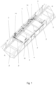
- Fig. 1 shows a conveying device 1 suitable for conveying object 5 (see fig. 2 ) according to an embodiment of the present disclosure, which can slide on at least two truss beams 3 of a truss 2 of a passenger conveying device.
- Fig. 2 shows an upper module of a passenger conveying device and/or a lower module of a passenger conveying device installed on a conveying device 1 according to the present disclosure.
- the object 5 to be transported is arranged on the conveying device 1 (see fig. 2 ).
- the truss 2 is arranged obliquely, and the conveying device 1 can move from a first position A to a second position B different from the first position A along the length of the truss 2 of the passenger conveyor, so as to transport the object to be transported from the first position A to the second position B, and vice versa.
- the passenger conveying device is an escalator.
- first position A and the second position B there may be no height difference between the first position A and the second position B, for example, at the entrance and exit of a pedestrian escalator as a passenger conveying device.
- the truss 2 of the passenger conveying device comprises a truss side bracket 4 and a plurality of truss beams 3.
- the plurality of truss beams 3 are connected between truss side brackets 4 and arranged at equal intervals along the length direction of the truss 2.
- the conveying device 1 is basically located in a frame recess 6 formed by the truss side brackets 4 and the plurality of truss beams 3, wherein the plurality of truss beams 3 support the conveying device 1 in the frame recess 6, and the truss side brackets 4 restrict the movement of the conveying device 1 in the frame recess 6 from both sides of the conveying device 1.
- the object 5 to be transported is an upper module of the passenger conveying device and/or a lower module of the passenger conveying device.
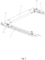
- Fig. 3 shows a schematic perspective view of a conveying device 1 according to an embodiment of the present disclosure, which includes a first longitudinal bracket 7, a second longitudinal bracket 8 and a first transverse bracket 9.
- the first transverse bracket 9 is connected between a first end of the first longitudinal bracket 7 and a first end of the second longitudinal bracket 8.
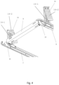
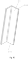
- first end of the first longitudinal bracket 7 and the first end of the second longitudinal bracket 8 are respectively provided with first arc-shaped parts 10 (see fig. 6 ).
- a second end of the first longitudinal bracket 7 and a second end of the second longitudinal bracket 8 are respectively provided with a second arc assembly 11.
- both the first end of the first longitudinal bracket 7 and the first end of the second longitudinal bracket 8 have arc-shaped ends 7-1 and 8-1.
- the first arc-shaped part 10 is fixedly fitted on the arc-shaped end 8-1 and is fitted on the bottom surfaces of the first longitudinal bracket 7 and the second longitudinal bracket 8.
- the second arc-shaped assembly 11 includes a first bending part 11-1, a second bending part 11-2, a third substrate 11-3 and a fourth arc-shaped part 11-4.
- a first end 11-1-1 of the first bending part 11-1 is fixedly connected to the second end of the first longitudinal bracket 7 and the second end of the second longitudinal bracket 8.
- a second end 11-1-2 of the first bending part 11-1 is fixedly connected to a first end 11-2-1 of the second bending part 11-2.
- the third substrate 11-3 is fixedly connected to the first bending part 11-1 and the second bending part 11-2.
- a second end 11-2-2 of the second bending part 11-2 is in an arc shape.
- the fourth arc-shaped part 11-4 is fixedly connected to the second end 11-2-2 of the second bending part 11-2 and an arc-shaped edge 11-3-1 of the third substrate 11-3.
- the fourth arc-shaped part 11-4 is fixedly connected to the bottom surfaces of the first longitudinal bracket 7 and the second longitudinal bracket 8.
- the third substrate 11-3 is provided with a third substrate through hole 11-3-2.
- the conveying device 1 further comprises a second transverse bracket 12.
- the second transverse bracket 12 is connected between the first ends 11-2-1 of the two second bending members 11-2.
- the first transverse bracket 9 and the second transverse bracket 12 have telescopic structures, so that the distance between the first longitudinal bracket 7 and the second longitudinal bracket 8 can be adjusted, thus being suitable for trusses of different types of passenger conveying devices.
- the distance between the first longitudinal bracket 7 and the second longitudinal bracket 8 is, for example, but not limited to, 600mm, 800mm or 1000 mm.
- the elongated first transverse bracket through holes may be formed at both ends of the first transverse bracket 9.
- the elongated second transverse bracket through holes are formed at both ends of the second transverse bracket 12.
- the first transverse bracket 9 is adjustably connected between the first end of the first longitudinal bracket 7 and the first end of the second longitudinal bracket 8 by fasteners passing through the first transverse bracket through holes.
- the second transverse bracket 12 can be adjustably connected between the first ends of the two second bending members 11-2 by fasteners passing through the second transverse bracket through holes.
- the conveying device 1 is provided with a wear-resistant components 13 made of a wear-resistant material, such as but not limited to polyamide (nylon).
- the wear-resistant components 13 can slide on the truss beam 3 in a frictional manner, thereby reducing the frictional resistance between the conveying device 1 and the truss beam 3 and reducing the wear of the bottom surfaces of the first longitudinal bracket 7 and the second longitudinal bracket 8 and the truss beam 3.
- the wear-resistant components 13 are fixedly installed on the bottom surfaces of the first longitudinal bracket 7 and the second longitudinal bracket 8.
- the conveying device 1 can slide not only on at least two truss beams 3 of a truss 2 of an escalator or a pedestrian escalator, but also on a flat or inclined ground.
- Two end portions of the wear-resistant components 13 are adjacent to the first arc-shaped part 10 and the fourth arc-shaped part 11-4 respectively and are arranged to smoothly transition with the first arc-shaped part 10 and the fourth arc-shaped part 11-4.
- the wear-resistant components 13 may also be formed on the arc surfaces of the first arc-shaped part 10 and the fourth arc-shaped part 11-4.
- the first arc-shaped part 10 and the fourth arc-shaped part 11-4 facilitate the conveying device to cross the bent corner portion (not shown) of the truss, such as the joint between the inclined part of the truss and an upper platform part and a lower platform part of the elevator.
- a plurality of module support parts 14 are provided on the top surfaces of the first longitudinal bracket 7 and the second longitudinal bracket 8.
- the module supporting part 14 is used for installing the object 5 to be transported and supporting the object 5 to be transported.
- Fig. 16 shows a schematic diagram in which the first longitudinal bracket 7 and the second longitudinal bracket 8 have two bracket sections, respectively, according to an embodiment of the present disclosure.
- the first longitudinal bracket 7 includes at least two first bracket sections 7-2, and two adjacent first bracket sections 7-2 are detachably connected together by fasteners.
- the second longitudinal bracket 8 includes at least two second bracket sections 8-2, and two adjacent second bracket sections 8-2 are detachably connected together by fasteners.
- the detachable first longitudinal bracket 7 and the detachable second longitudinal bracket 8 are beneficial to disassembling the conveying device 1 into a smaller volume after the conveying work is completed, and are further beneficial to transportation and storage.
- each bracket section of the first longitudinal bracket 7 and the second longitudinal bracket 8 can have a telescopic structure, so that the conveying device can be adapted to truss beams with different distances.
- Fig. 17 shows a schematic perspective view of a first longitudinal guardrail assembly 15 and a second longitudinal guardrail assembly 16 according to an embodiment of the present disclosure.
- the conveying device 1 further includes the first longitudinal guardrail assembly 15 and the second longitudinal guardrail assembly 16.
- the first longitudinal guardrail assembly 15 is adjustably connected to the first longitudinal bracket 7 and located outside the first longitudinal bracket 7.
- the second longitudinal guardrail assembly 16 is adjustably connected to the second longitudinal bracket 8 and located outside the second longitudinal bracket 8.
- the distance between the first longitudinal guardrail assembly 15 and the second longitudinal guardrail assembly 16 can be adjusted.
- the first longitudinal guardrail assembly 15 and the second longitudinal guardrail assembly 16 help to prevent the truss side bracket 4 from colliding with the first longitudinal bracket 7 and the second longitudinal bracket 8.
- the lengths of the first longitudinal guardrail assembly 15 and the second longitudinal guardrail assembly 16 are longer than those of the first longitudinal bracket 7 and the second longitudinal bracket 8, and two end portions of the first longitudinal guardrail assembly 15 and the second longitudinal guardrail assembly 16 respectively exceed the first transverse bracket 9 and the second transverse bracket 12.
- the first longitudinal guardrail assembly 15 includes a first longitudinal guardrail body 15-1 and a plurality of first longitudinal guardrail connectors 15-2.
- the two ends of the first longitudinal guardrail body 15-1 are curved bends.
- the plurality of first longitudinal guardrail connectors 15-2 are connected to the first longitudinal guardrail body 15-1 and arranged at equal intervals along the length direction of the first longitudinal guardrail body 15-1.
- the second longitudinal guardrail assembly 16 includes a second longitudinal guardrail body 16-1 and a plurality of second longitudinal guardrail connectors 16-2.
- the two end portions of the second longitudinal guardrail body 16-1 are curved bends.
- the plurality of second longitudinal guardrail connectors 16-2 are connected to the second longitudinal guardrail body 16-1 and arranged at equal intervals along the length direction of the second longitudinal guardrail body 16-1.
- the first longitudinal guardrail connector 15-2 is provided with an elongated first longitudinal guardrail through hole 15-3.
- the first longitudinal guardrail connector 15-2 can be adjustably connected to the first longitudinal bracket 7 by a fastener passing through the first longitudinal guardrail through hole 15-3.
- the second longitudinal guardrail connector 16-2 is provided with an elongated second longitudinal guardrail through hole 16-3.
- the second longitudinal guardrail connector 16-2 can be adjustably connected to the second longitudinal bracket 8 by a fastener passing through the second longitudinal guardrail through hole 16-3.
- the module supporting member 14 is provided with a plurality of module mounting grooves 14-1, module fastener holes 14-2, module mounting notches 14-3 and module spindle through holes 14-4.
- the plurality of module mounting grooves 14-1, module fastener holes 14-2, module mounting notches 14-3 and module spindle through holes 14-4 are configured for mounting the upper module and/or the lower module on the first longitudinal bracket 7 and the second longitudinal bracket 8.
- the first longitudinal bracket 7 and the second longitudinal bracket 8 of the conveying device can slide on the plurality of truss beams 3.
- the first longitudinal bracket 7, the second longitudinal bracket 8, the first transverse bracket 9, the second transverse bracket 12, the first longitudinal guardrail assembly 15 and the second longitudinal guardrail assembly 16 of the conveying device are all located between the truss side brackets 4 and within the height range of the truss side brackets 4.
Landscapes
- Engineering & Computer Science (AREA)
- Mechanical Engineering (AREA)
- Escalators And Moving Walkways (AREA)
Abstract
Description
- The present disclosure relates to a conveying device suitable for conveying object, in particular to a conveying device suitable for conveying object on a truss beam of a passenger conveying device or on an ordinary step.
- For the solution of modernization of passenger conveyor, it is necessary to remove all the old passenger conveyor modules, but keep the truss of passenger conveyor. Then, a new passenger conveyor module needs to be installed on site, for example, an upper module of the passenger conveyor and a lower module of the passenger conveyor need to be installed on site.
- In many cases, especially indoor passenger transport devices, elevator modules cannot be transported from one floor to another by elevators or hoists because of limited space. Therefore, it is necessary to design a conveying device that can slide on the truss beam of the passenger conveyor or on ordinary steps, which is used to transport heavy or large-volume objects, such as but not limited to the upper module of the passenger conveyor and the lower module of the passenger conveyor.
- In order to solve one or more defects in the prior art, according to one aspect of the present disclosure, a conveying device suitable for conveying objects is proposed, wherein the conveying device can slide on at least two truss beams of a truss of a passenger conveying device.
- The object to be transported is arranged on the conveying device.
- The conveying device can move from a first position to a second position different from the first position along the length of the truss of the passenger conveying device, thereby conveying the objects to be conveyed from the first position to the second position.
- According to the above aspect of the present disclosure, there is a height difference between the first position and the second position, or there is no height difference between the first position and the second position.
- According to the above aspects of the present disclosure, the conveying device is provided with a wear-resistant component made of a wear-resistant material. The wear-resistant components are frictionally sliding on the truss beam.
- According to the above aspects of the present disclosure, the wear-resistant material is polyamide (nylon).
- According to the above aspects of the present disclosure, the conveying device includes a first longitudinal bracket, a second longitudinal bracket and a first transverse bracket.
- The first transverse bracket is connected between a first end of the first longitudinal bracket and a first end of the second longitudinal bracket.
- The first end of the first longitudinal bracket and the first end of the second longitudinal bracket are respectively provided with first arc-shaped parts.
- A second end of the first longitudinal bracket and a second end of the second longitudinal bracket are respectively provided with a second arc-shaped assembly.
- According to the above aspects of the present disclosure, both the first end of the first longitudinal bracket and the first end of the second longitudinal bracket have arc-shaped ends.
- The first arc-shaped part is fixedly fitted on the arc-shaped end part and the first arc-shaped part is fitted on the bottom surfaces of the first longitudinal bracket and the second longitudinal bracket.
- According to the above aspects of the present disclosure, the second arc-shaped assembly includes a first bending part, a second bending part, a third substrate and a fourth arc-shaped part.
- A first end of the first bending part is fixedly connected to the second end of the first longitudinal bracket and the second end of the second longitudinal bracket.
- A second end of the first bending member is fixedly connected to a first end of the second bending member.
- The third substrate is fixedly connected to the first bending part and the second bending part.
- A second end of the second bending part is arc-shaped.
- The fourth arc-shaped part is fixedly connected to the second end of the second bending part and the arc-shaped edge of the third substrate.
- At the second end of the first longitudinal bracket and the second end of the second longitudinal bracket, the fourth arc-shaped part is fixedly connected to the bottom surfaces of the first longitudinal bracket and the second longitudinal bracket.
- According to the above aspects of the present disclosure, a third substrate through hole is provided on the third substrate.
- According to the above aspects of the present disclosure, the conveying device further comprises a second transverse bracket.
- The second transverse bracket is connected between the first ends of the two second bending parts.
- According to the above aspects of the present disclosure, the first transverse bracket and the second transverse bracket have telescopic structures, so that the distance between the first longitudinal bracket and the second longitudinal bracket can be adjusted.
- According to the above-mentioned aspects of the present disclosure, first transverse bracket through holes in an elongated shape are formed on both ends of the first transverse bracket.
- Second transverse bracket through holes in an elongated shape are formed on both ends of the second transverse bracket.
- The first transverse bracket can be adjustably connected between the first end of the first longitudinal bracket and the first end of the second longitudinal bracket through a fastener passing through the through hole of the first transverse bracket.
- The second transverse bracket can be adjustably connected between the first ends of the two second bending parts by a fastener passing through the through hole of the second transverse bracket.
- According to the above aspects of the present disclosure, the wear-resistant components are fixedly installed on the bottom surfaces of the first longitudinal bracket and the second longitudinal bracket.
- Two end parts of the wear-resistant components are adjacent to the first arc-shaped part and the fourth arc-shaped part respectively and are arranged to smoothly transition with the first arc-shaped part and the fourth arc-shaped part.
- The wear-resistant components can slide on the truss beam in friction, thereby reducing the frictional resistance between the conveying device and the truss beam and reducing the wear of the bottom surfaces of the first longitudinal bracket and the second longitudinal bracket and the truss beam.
- According to the above aspects of the present disclosure, a plurality of module supporting parts are provided on the top surfaces of the first longitudinal bracket and the second longitudinal bracket.
- The module supporting parts are used for installing the object to be transported and supporting the object to be transported.
- According to the above aspects of the present disclosure, the first longitudinal bracket includes at least two first bracket sections, and two first bracket sections adjacent to each other are detachably connected together by fasteners.
- The second longitudinal bracket comprises at least two second bracket sections, and two adjacent second bracket sections are detachably connected together through fasteners.
- The dismountable first longitudinal bracket and the dismountable second longitudinal bracket are beneficial to dismounting the conveying device into a smaller volume after the conveying work is completed, thereby being beneficial to transportation and storage.
- It can also be understood by those skilled in the art that each bracket section of the first longitudinal bracket and the second longitudinal bracket can have a telescopic structure, so that the conveying device can be adapted to truss beams with different distances.
- According to the above aspects of the present disclosure, the conveying device further comprises a first longitudinal guardrail assembly and a second longitudinal guardrail assembly.
- The first longitudinal guardrail assembly can be adjustably connected to the first longitudinal bracket and located outside the first longitudinal bracket.
- The second longitudinal guardrail assembly can be adjustably connected to the second longitudinal bracket and located outside the second longitudinal bracket.
- The distance between the first longitudinal guardrail assembly and the second longitudinal guardrail assembly can be adjusted.
- According to the above aspects of the present disclosure, the first longitudinal guardrail assembly includes a first longitudinal guardrail body and a plurality of first longitudinal guardrail connectors.
- The plurality of first longitudinal guardrail connectors are connected to the first longitudinal guardrail body and are arranged at equal intervals along the length direction of the first longitudinal guardrail body.
- The second longitudinal guardrail assembly comprises a second longitudinal guardrail body and a plurality of second longitudinal guardrail connectors.
- The plurality of second longitudinal guardrail connectors are connected to the second longitudinal guardrail body and are arranged at equal intervals along the length direction of the second longitudinal guardrail body.
- According to the above aspects of the present disclosure, the first longitudinal guardrail connector is provided with an elongated first longitudinal guardrail through hole.
- The first longitudinal guardrail connector can be adjustably connected to the first longitudinal bracket through a fastener passing through the first longitudinal guardrail through hole.
- The second longitudinal guardrail connector is provided with an elongated second longitudinal guardrail through hole.
- The second longitudinal guardrail connector can be adjustably connected to the second longitudinal bracket through a fastener passing through the second longitudinal guardrail through hole.
- The first longitudinal guardrail assembly and the second longitudinal guardrail assembly help to prevent the truss side bracket from colliding with the first longitudinal bracket and the second longitudinal bracket.
- According to the above aspects of the present disclosure, the object to be transported is an upper module of the passenger conveying device and/or a lower module of the passenger conveying device.
- According to the above aspects of the present disclosure, the module supporting part is provided with a plurality of module mounting grooves, module fastener holes, module mounting notches and module spindle through holes.
- The plurality of module mounting grooves, module fastener holes, module mounting notches and module spindle through holes are used for mounting the upper module and/or the lower module on the first longitudinal bracket and the second longitudinal bracket.
- According to the above aspects of the present disclosure, the truss of the passenger conveying device includes a truss side bracket and a plurality of truss beams.
- The plurality of truss beams are connected between truss side brackets and arranged at equal intervals along the length direction of the truss.
- The first longitudinal bracket and the second longitudinal bracket of the conveying device can slide on the plurality of truss beams.
- The first longitudinal bracket, the second longitudinal bracket, the first transverse bracket, the second transverse bracket, the first longitudinal guardrail component and the second longitudinal guardrail component of the conveying device are all located between the truss side brackets and within the height range of the truss side brackets.
- The conveying device for conveying heavy objects according to the present disclosure can be used for the modernization of passenger conveying devices.
- The conveying device according to the present disclosure can slide on the truss beams of the truss or on ordinary steps, and can safely transport heavy objects from a first position with height difference to a second position, and vice versa. It solves the problem that the limited space cannot transport large-volume objects.
- The conveying device according to the present disclosure has a longitudinal bracket that can slide on the truss beam or the normal steps on site and has a first longitudinal guardrail assembly and a second longitudinal guardrail assembly to ensure the correct sliding of the conveying device. In addition, a winch or other towing machine can be installed at the top of the truss to tow the conveying device.
- The prior art solution is to disassemble the module into small parts, put these small parts on the upper or lower floor of the elevator, and then install them on site. Compared with the prior art solution that modules need to be assembled on site and good accuracy cannot be maintained for assembly, the conveying device according to the present disclosure (pre-assembled elevator modules will be installed on the conveying device in advance) can save installation time, ensure good installation accuracy, and further save installation cost.
- So far, in order that the detailed description of the disclosure herein can be better understood and the contribution of the disclosure to the prior art can be better realized, the disclosure has outlined the contents of the disclosure quite broadly. Of course, embodiments of the present disclosure will be described below and will form the subject of the appended claims.
- Likewise, those skilled in the art will recognize that the concept on which this disclosure is based can be easily used as a basis for designing other structures, methods and systems for carrying out the several purposes of this disclosure. Therefore, it is important that the appended claims should be regarded as including such equivalent structures as long as they do not exceed the spirit and scope of this disclosure.
- Those skilled in the art will have a better understanding of this disclosure through the following drawings, and the advantages of this disclosure can be more clearly reflected. The drawings described here are only for illustrative purposes of selected embodiments, not all possible implementations, and are not intended to limit the scope of the present disclosure.
-
Fig. 1 shows a conveying device suitable for conveying objects according to the present disclosure, which can slide on a truss beam of a truss of a passenger conveying device; -
Fig. 2 shows an upper module of a passenger conveyor and/or a lower module of a passenger conveyor installed on a conveying device according to the present disclosure; -
Fig. 3 shows a schematic perspective view of a conveying device according to the present disclosure; -
Fig. 4 shows a schematic perspective view of a first end of a conveying device according to the present disclosure, which shows the bottom of the conveying device; -
Fig. 5 is a partially simplified view offig. 4 ; -
Fig. 6 shows a schematic perspective view of a first arc-shaped part according to the present disclosure; -
Figs. 7 and8 are perspective schematic views showing the second end of the conveying device according to the present disclosure from different perspectives, respectively; -
Fig. 9 shows a perspective schematic view of the first and second longitudinal brackets and a second arc-shaped assembly installed on the first and second longitudinal brackets according to the present disclosure; -
Fig. 10 shows a schematic perspective view of a first bending part according to the present disclosure; -
Fig. 11 shows a perspective schematic view of a second bending part according to the present disclosure; -
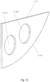
Fig. 12 shows a schematic perspective view of a third substrate according to the present disclosure; -
Fig. 13 shows a perspective schematic view of a fourth arc-shaped part in an arc shape according to the present disclosure; -
Fig. 14 shows a wear-resistant component according to the present disclosure; -
Fig. 15 shows a bottom view of the conveying device according to the present disclosure, in which wear-resistant components are installed on the bottom surfaces of the first longitudinal bracket and the second longitudinal bracket, respectively; -
Fig. 16 shows a schematic view of a first longitudinal bracket and a second longitudinal bracket respectively having two bracket sections according to the present disclosure; -
Fig. 17 shows a schematic perspective view of a first longitudinal guardrail assembly and a second longitudinal guardrail assembly according to the present disclosure. - Hereinafter, a specific embodiment according to the present disclosure will be described in detail with reference to each of
figs. 1 to 17 . -
Fig. 1 shows a conveyingdevice 1 suitable for conveying object 5 (seefig. 2 ) according to an embodiment of the present disclosure, which can slide on at least twotruss beams 3 of atruss 2 of a passenger conveying device. -
Fig. 2 shows an upper module of a passenger conveying device and/or a lower module of a passenger conveying device installed on a conveyingdevice 1 according to the present disclosure. - The
object 5 to be transported is arranged on the conveying device 1 (seefig. 2 ). Infig. 1 , thetruss 2 is arranged obliquely, and the conveyingdevice 1 can move from a first position A to a second position B different from the first position A along the length of thetruss 2 of the passenger conveyor, so as to transport the object to be transported from the first position A to the second position B, and vice versa. For example, the passenger conveying device is an escalator. - There is a height difference between the first position A and the second position B.
- It can also be understood by those skilled in the art that there may be no height difference between the first position A and the second position B, for example, at the entrance and exit of a pedestrian escalator as a passenger conveying device.
- The
truss 2 of the passenger conveying device comprises atruss side bracket 4 and a plurality of truss beams 3. - The plurality of
truss beams 3 are connected betweentruss side brackets 4 and arranged at equal intervals along the length direction of thetruss 2. - In the configuration shown in
figs. 1 and2 , the conveyingdevice 1 is basically located in aframe recess 6 formed by thetruss side brackets 4 and the plurality oftruss beams 3, wherein the plurality oftruss beams 3 support the conveyingdevice 1 in theframe recess 6, and thetruss side brackets 4 restrict the movement of the conveyingdevice 1 in theframe recess 6 from both sides of the conveyingdevice 1. - The
object 5 to be transported is an upper module of the passenger conveying device and/or a lower module of the passenger conveying device. -
Fig. 3 shows a schematic perspective view of a conveyingdevice 1 according to an embodiment of the present disclosure, which includes a firstlongitudinal bracket 7, a secondlongitudinal bracket 8 and a firsttransverse bracket 9. - The first
transverse bracket 9 is connected between a first end of the firstlongitudinal bracket 7 and a first end of the secondlongitudinal bracket 8. - As shown in
fig. 4 , the first end of the firstlongitudinal bracket 7 and the first end of the secondlongitudinal bracket 8 are respectively provided with first arc-shaped parts 10 (seefig. 6 ). - A second end of the first
longitudinal bracket 7 and a second end of the secondlongitudinal bracket 8 are respectively provided with asecond arc assembly 11. - As shown in
fig. 5 , both the first end of the firstlongitudinal bracket 7 and the first end of the secondlongitudinal bracket 8 have arc-shaped ends 7-1 and 8-1. - The first arc-shaped
part 10 is fixedly fitted on the arc-shaped end 8-1 and is fitted on the bottom surfaces of the firstlongitudinal bracket 7 and the secondlongitudinal bracket 8. - As shown in
figs. 7 to 13 , the second arc-shapedassembly 11 includes a first bending part 11-1, a second bending part 11-2, a third substrate 11-3 and a fourth arc-shaped part 11-4. - A first end 11-1-1 of the first bending part 11-1 is fixedly connected to the second end of the first
longitudinal bracket 7 and the second end of the secondlongitudinal bracket 8. - A second end 11-1-2 of the first bending part 11-1 is fixedly connected to a first end 11-2-1 of the second bending part 11-2.
- The third substrate 11-3 is fixedly connected to the first bending part 11-1 and the second bending part 11-2.
- A second end 11-2-2 of the second bending part 11-2 is in an arc shape.
- The fourth arc-shaped part 11-4 is fixedly connected to the second end 11-2-2 of the second bending part 11-2 and an arc-shaped edge 11-3-1 of the third substrate 11-3.
- At the second end of the first
longitudinal bracket 7 and the second end of the secondlongitudinal bracket 8, the fourth arc-shaped part 11-4 is fixedly connected to the bottom surfaces of the firstlongitudinal bracket 7 and the secondlongitudinal bracket 8. - The third substrate 11-3 is provided with a third substrate through hole 11-3-2.
- The conveying
device 1 further comprises a secondtransverse bracket 12. - The second
transverse bracket 12 is connected between the first ends 11-2-1 of the two second bending members 11-2. - The first
transverse bracket 9 and the secondtransverse bracket 12 have telescopic structures, so that the distance between the firstlongitudinal bracket 7 and the secondlongitudinal bracket 8 can be adjusted, thus being suitable for trusses of different types of passenger conveying devices. For example, the distance between the firstlongitudinal bracket 7 and the secondlongitudinal bracket 8 is, for example, but not limited to, 600mm, 800mm or 1000 mm. - In addition to the telescopic structure of the first
transverse bracket 9 and the secondtransverse bracket 12, the elongated first transverse bracket through holes may be formed at both ends of the firsttransverse bracket 9. - The elongated second transverse bracket through holes are formed at both ends of the second
transverse bracket 12. - The first
transverse bracket 9 is adjustably connected between the first end of the firstlongitudinal bracket 7 and the first end of the secondlongitudinal bracket 8 by fasteners passing through the first transverse bracket through holes. - The second
transverse bracket 12 can be adjustably connected between the first ends of the two second bending members 11-2 by fasteners passing through the second transverse bracket through holes. - As shown in
fig. 14 , the conveyingdevice 1 is provided with a wear-resistant components 13 made of a wear-resistant material, such as but not limited to polyamide (nylon). - The wear-
resistant components 13 can slide on thetruss beam 3 in a frictional manner, thereby reducing the frictional resistance between the conveyingdevice 1 and thetruss beam 3 and reducing the wear of the bottom surfaces of the firstlongitudinal bracket 7 and the secondlongitudinal bracket 8 and thetruss beam 3. - The wear-
resistant components 13 are fixedly installed on the bottom surfaces of the firstlongitudinal bracket 7 and the secondlongitudinal bracket 8. - The conveying
device 1 can slide not only on at least twotruss beams 3 of atruss 2 of an escalator or a pedestrian escalator, but also on a flat or inclined ground. - Two end portions of the wear-
resistant components 13 are adjacent to the first arc-shapedpart 10 and the fourth arc-shaped part 11-4 respectively and are arranged to smoothly transition with the first arc-shapedpart 10 and the fourth arc-shaped part 11-4. - The wear-
resistant components 13 may also be formed on the arc surfaces of the first arc-shapedpart 10 and the fourth arc-shaped part 11-4. The first arc-shapedpart 10 and the fourth arc-shaped part 11-4 facilitate the conveying device to cross the bent corner portion (not shown) of the truss, such as the joint between the inclined part of the truss and an upper platform part and a lower platform part of the elevator. - As shown in
figs. 3 and4 , a plurality ofmodule support parts 14 are provided on the top surfaces of the firstlongitudinal bracket 7 and the secondlongitudinal bracket 8. - The
module supporting part 14 is used for installing theobject 5 to be transported and supporting theobject 5 to be transported. -
Fig. 16 shows a schematic diagram in which the firstlongitudinal bracket 7 and the secondlongitudinal bracket 8 have two bracket sections, respectively, according to an embodiment of the present disclosure. As shown infig. 16 , the firstlongitudinal bracket 7 includes at least two first bracket sections 7-2, and two adjacent first bracket sections 7-2 are detachably connected together by fasteners. - The second
longitudinal bracket 8 includes at least two second bracket sections 8-2, and two adjacent second bracket sections 8-2 are detachably connected together by fasteners. - The detachable first
longitudinal bracket 7 and the detachable secondlongitudinal bracket 8 are beneficial to disassembling the conveyingdevice 1 into a smaller volume after the conveying work is completed, and are further beneficial to transportation and storage. - It can also be understood by those skilled in the art that each bracket section of the first
longitudinal bracket 7 and the secondlongitudinal bracket 8 can have a telescopic structure, so that the conveying device can be adapted to truss beams with different distances. -
Fig. 17 shows a schematic perspective view of a firstlongitudinal guardrail assembly 15 and a secondlongitudinal guardrail assembly 16 according to an embodiment of the present disclosure. As shown infig. 17 , the conveyingdevice 1 further includes the firstlongitudinal guardrail assembly 15 and the secondlongitudinal guardrail assembly 16. - The first
longitudinal guardrail assembly 15 is adjustably connected to the firstlongitudinal bracket 7 and located outside the firstlongitudinal bracket 7. - The second
longitudinal guardrail assembly 16 is adjustably connected to the secondlongitudinal bracket 8 and located outside the secondlongitudinal bracket 8. - The distance between the first
longitudinal guardrail assembly 15 and the secondlongitudinal guardrail assembly 16 can be adjusted. - The first
longitudinal guardrail assembly 15 and the secondlongitudinal guardrail assembly 16 help to prevent thetruss side bracket 4 from colliding with the firstlongitudinal bracket 7 and the secondlongitudinal bracket 8. - The lengths of the first
longitudinal guardrail assembly 15 and the secondlongitudinal guardrail assembly 16 are longer than those of the firstlongitudinal bracket 7 and the secondlongitudinal bracket 8, and two end portions of the firstlongitudinal guardrail assembly 15 and the secondlongitudinal guardrail assembly 16 respectively exceed the firsttransverse bracket 9 and the secondtransverse bracket 12. - The first
longitudinal guardrail assembly 15 includes a first longitudinal guardrail body 15-1 and a plurality of first longitudinal guardrail connectors 15-2. - The two ends of the first longitudinal guardrail body 15-1 are curved bends.
- The plurality of first longitudinal guardrail connectors 15-2 are connected to the first longitudinal guardrail body 15-1 and arranged at equal intervals along the length direction of the first longitudinal guardrail body 15-1.
- The second
longitudinal guardrail assembly 16 includes a second longitudinal guardrail body 16-1 and a plurality of second longitudinal guardrail connectors 16-2. - The two end portions of the second longitudinal guardrail body 16-1 are curved bends.
- The plurality of second longitudinal guardrail connectors 16-2 are connected to the second longitudinal guardrail body 16-1 and arranged at equal intervals along the length direction of the second longitudinal guardrail body 16-1.
- The first longitudinal guardrail connector 15-2 is provided with an elongated first longitudinal guardrail through hole 15-3.
- The first longitudinal guardrail connector 15-2 can be adjustably connected to the first
longitudinal bracket 7 by a fastener passing through the first longitudinal guardrail through hole 15-3. - The second longitudinal guardrail connector 16-2 is provided with an elongated second longitudinal guardrail through hole 16-3.
- The second longitudinal guardrail connector 16-2 can be adjustably connected to the second
longitudinal bracket 8 by a fastener passing through the second longitudinal guardrail through hole 16-3. - The
module supporting member 14 is provided with a plurality of module mounting grooves 14-1, module fastener holes 14-2, module mounting notches 14-3 and module spindle through holes 14-4. - The plurality of module mounting grooves 14-1, module fastener holes 14-2, module mounting notches 14-3 and module spindle through holes 14-4 are configured for mounting the upper module and/or the lower module on the first
longitudinal bracket 7 and the secondlongitudinal bracket 8. - The first
longitudinal bracket 7 and the secondlongitudinal bracket 8 of the conveying device can slide on the plurality of truss beams 3. - The first
longitudinal bracket 7, the secondlongitudinal bracket 8, the firsttransverse bracket 9, the secondtransverse bracket 12, the firstlongitudinal guardrail assembly 15 and the secondlongitudinal guardrail assembly 16 of the conveying device are all located between thetruss side brackets 4 and within the height range of thetruss side brackets 4. - The foregoing disclosure provides illustration and description, but is not intended to be exhaustive or to limit the embodiments to the precise forms disclosed. Modifications and variations are possible in light of the above disclosure, or may be acquired from practice of the embodiments.
- Even if specific combinations of features are recited in the claims and/or disclosed in the specification, these combinations are not intended to limit the disclosure of various embodiments. In fact, many of these features can be combined in ways not specifically recited in the claims and/or not specifically disclosed in the specification. Although each dependent claim listed below may directly depend on only one claim, the disclosure of various embodiments includes each dependent claim in combination with every other claim in the claim set.
Claims (15)
- A conveying device (1) suitable for conveying object (5), wherein,the conveying device can slide on at least two truss beams (3) of the truss (2) of passenger conveying device;setting said object to be transported on the conveying device;the conveying device can move from a first position (A) to a second position (B) different from the first position along the length of the truss of the passenger conveying device, thereby conveying said object to be transported from the first position to the second position.
- The conveying device according to claim 1, wherein,there is a height difference between the first position and the second position, or there is no height difference between the first position and the second position; or wherein,wear-resistant components (13) made of wear-resistant material are arranged on the conveying device;the wear-resistant components are frictionally sliding on the truss beam.
- The conveying device according to claim 2, wherein,
the wear-resistant material is polyamide (nylon). - The conveying device according to claim 3, wherein,the conveying device comprises a first longitudinal bracket (7), a second longitudinal bracket (8) and a first transverse bracket (9);the first transverse bracket is connected between a first end of the first longitudinal bracket and a first end of the second longitudinal bracket;the first end of the first longitudinal bracket and the first end of the second longitudinal bracket are respectively provided with first arc-shaped parts (10);a second end of the first longitudinal bracket and a second end of the second longitudinal bracket are respectively provided with a second arc-shaped assembly (11).
- The conveying device according to claim 4, wherein,the first end of the first longitudinal bracket and the first end of the second longitudinal bracket both have arc-shaped ends (7-1; 8-1);the first arc-shaped part is fixedly fitted on the arc-shaped end part and the first arc-shaped part is fitted on bottom surfaces of the first longitudinal bracket and the second longitudinal bracket;
or wherein,the second arc-shaped assembly (11) comprises first bending parts (11-1), second bending parts (11-2), a third substrate (11-3) and a fourth arc-shaped part (11-4);a first end of the first bending part is fixedly connected to the second end of the first longitudinal bracket and the second end of the second longitudinal bracket; a second end of the first bending part is fixedly connected to a first end of the second bending part;the third substrate is fixedly connected to the first bending part and the second bending part;the second end of the second bending part is arc-shaped;the fourth arc-shaped part is fixedly connected to a second end of the second bending part and the arc-shaped edge (11-3-1) of the third substrate; andat the second end of the first longitudinal bracket and the second end of the second longitudinal bracket, the fourth arc-shaped part is fixedly connected to the bottom surfaces of the first longitudinal bracket and the second longitudinal bracket. - The conveying device according to claim 5, wherein,a third substrate through hole (11-3-2) is arranged on the third substrate;
or wherein,the conveying device (1) further comprises a second transverse bracket (12);the second transverse bracket is connected between the first ends (11-2-1) of the two second bending parts. - The conveying device according to claim 6, wherein,the first transverse bracket and the second transverse bracket have telescopic structures, so that the distance between the first longitudinal bracket and the second longitudinal bracket can be adjusted;
or wherein,forming elongated first transverse bracket through holes on both ends of the first transverse bracket;forming elongated second transverse bracket through holes on both ends of the second transverse bracket;the first transverse bracket can be adjustably connected between the first end of the first longitudinal bracket and the first end of the second longitudinal bracket through a fastener passing through the through hole of the first transverse bracket;the second transverse bracket can be adjustably connected between the first ends of the two second bending parts by a fastener passing through the through hole of the second transverse bracket. - The conveying device according to claim 6, wherein,the wear-resistant components (13) are fixedly installed on the bottom surfaces of the first longitudinal bracket and the second longitudinal bracket;two end parts of the wear-resistant component are adjacent to the first arc-shaped part and the fourth arc-shaped part respectively and are arranged to smoothly transition with the first arc-shaped part and the fourth arc-shaped part; or wherein,a plurality of module supporting parts (14) are arranged on the top surfaces of the first longitudinal bracket and the second longitudinal bracket;the module supporting part is used for installing the object to be transported and supporting the object to be transported.
- The conveying device according to claim 8, wherein,the first longitudinal bracket (7) comprises at least two first bracket sections (7-2), and two adjacent first bracket sections are detachably connected together through fasteners;the second longitudinal bracket (8) comprises at least two second bracket sections (8-2), and two adjacent second bracket sections are detachably connected together through fasteners.
- The conveying device according to claim 8, wherein,the conveying device further comprises a first longitudinal guardrail assembly (15) and a second longitudinal guardrail assembly (16);the first longitudinal guardrail assembly can be adjustably connected to the first longitudinal bracket and positioned outside the first longitudinal bracket;the second longitudinal guardrail assembly can be adjustably connected to the second longitudinal bracket and positioned outside the second longitudinal bracket;the distance between the first longitudinal guardrail assembly and the second longitudinal guardrail assembly can be adjusted.
- The conveying device according to claim 10, wherein,the first longitudinal guardrail assembly comprises a first longitudinal guardrail body (15-1) and a plurality of first longitudinal guardrail connectors (15-2);the plurality of first longitudinal guardrail connectors are connected to the first longitudinal guardrail body and are arranged at equal intervals along the length direction of the first longitudinal guardrail body;the second longitudinal guardrail assembly comprises a second longitudinal guardrail body (16-1) and a plurality of second longitudinal guardrail connectors (16-2);the plurality of second longitudinal guardrail connectors are connected to the second longitudinal guardrail body and are arranged at equal intervals along the length direction of the second longitudinal guardrail body.
- The conveying device according to claim 11, wherein,the first longitudinal guardrail connector is provided with an elongated first longitudinal guardrail through hole (15-3);the first longitudinal guardrail connector can be adjustably connected to the first longitudinal bracket through a fastener passing through the first longitudinal guardrail through hole;the second longitudinal guardrail connector is provided with an elongated second longitudinal guardrail through hole (16-3);the second longitudinal guardrail connector can be adjustably connected to the second longitudinal bracket through a fastener passing through the second longitudinal guardrail through hole.
- The conveying device according to claim 12, wherein,
the object to be transported is an upper module of the passenger conveying device and/or a lower module of the passenger conveying device. - The conveying device according to claim 13, wherein,the module supporting part is provided with a plurality of module mounting grooves (14-1), module fastener holes (14-2), module mounting notches (14-3) and module spindle through holes (14-4);the plurality of module mounting grooves, module fastener holes, module mounting notches and module spindle through holes are used for mounting the upper module and/or the lower module on the first longitudinal bracket and the second longitudinal bracket.
- The conveying device according to claim 6, wherein,the truss (2) of the passenger conveying device (1) comprises a truss side bracket (4) and a plurality of truss beams (3);the plurality of truss beams are connected between truss side brackets and arranged at equal intervals along the length direction of the truss;the first longitudinal bracket and the second longitudinal bracket of the conveying device can slide on the plurality of truss beams;the first longitudinal bracket, the second longitudinal bracket, the first transverse bracket, the second transverse bracket, the first longitudinal guardrail assembly and the second longitudinal guardrail assembly of the conveying device are all located between the truss side brackets and within the height range of the truss side brackets.
Applications Claiming Priority (1)
| Application Number | Priority Date | Filing Date | Title |
|---|---|---|---|
| CN202310043126.6A CN116253225A (en) | 2023-01-12 | 2023-01-12 | A handling device suitable for handling materials |
Publications (1)
| Publication Number | Publication Date |
|---|---|
| EP4400468A1 true EP4400468A1 (en) | 2024-07-17 |
Family
ID=86685626
Family Applications (1)
| Application Number | Title | Priority Date | Filing Date |
|---|---|---|---|
| EP24150839.9A Pending EP4400468A1 (en) | 2023-01-12 | 2024-01-09 | A conveying device suitable for conveying object |
Country Status (3)
| Country | Link |
|---|---|
| US (1) | US20240239612A1 (en) |
| EP (1) | EP4400468A1 (en) |
| CN (1) | CN116253225A (en) |
Citations (4)
| Publication number | Priority date | Publication date | Assignee | Title |
|---|---|---|---|---|
| JP2002226165A (en) * | 2001-01-30 | 2002-08-14 | Hitachi Building Systems Co Ltd | Transport device for escalator |
| JP2007290826A (en) * | 2006-04-26 | 2007-11-08 | Hitachi Ltd | Passenger conveyor component delivery method, component delivery method, passenger conveyor repair method using the same, and passenger conveyor component delivery device used therefor |
| US20150239711A1 (en) * | 2012-09-27 | 2015-08-27 | Inventio Ag | Track System for an Escalator or Moving Walkway |
| WO2020179013A1 (en) * | 2019-03-06 | 2020-09-10 | 三菱電機ビルテクノサービス株式会社 | Escalator equipment transportation device |
Family Cites Families (2)
| Publication number | Priority date | Publication date | Assignee | Title |
|---|---|---|---|---|
| JP2011251800A (en) * | 2010-06-01 | 2011-12-15 | Toshiba Elevator Co Ltd | Method of replacing passenger conveyors |
| CN220998866U (en) * | 2023-01-12 | 2024-05-24 | 通力电梯有限公司 | Handling device suitable for carry material |
-
2023
- 2023-01-12 CN CN202310043126.6A patent/CN116253225A/en active Pending
-
2024
- 2024-01-02 US US18/402,157 patent/US20240239612A1/en active Pending
- 2024-01-09 EP EP24150839.9A patent/EP4400468A1/en active Pending
Patent Citations (4)
| Publication number | Priority date | Publication date | Assignee | Title |
|---|---|---|---|---|
| JP2002226165A (en) * | 2001-01-30 | 2002-08-14 | Hitachi Building Systems Co Ltd | Transport device for escalator |
| JP2007290826A (en) * | 2006-04-26 | 2007-11-08 | Hitachi Ltd | Passenger conveyor component delivery method, component delivery method, passenger conveyor repair method using the same, and passenger conveyor component delivery device used therefor |
| US20150239711A1 (en) * | 2012-09-27 | 2015-08-27 | Inventio Ag | Track System for an Escalator or Moving Walkway |
| WO2020179013A1 (en) * | 2019-03-06 | 2020-09-10 | 三菱電機ビルテクノサービス株式会社 | Escalator equipment transportation device |
Non-Patent Citations (2)
| Title |
|---|
| DATABASE WPI Week 200268, Derwent World Patents Index; AN 2002-632168 * |
| DATABASE WPI Week 200781, Derwent World Patents Index; AN 2007-878227 * |
Also Published As
| Publication number | Publication date |
|---|---|
| US20240239612A1 (en) | 2024-07-18 |
| CN116253225A (en) | 2023-06-13 |
Similar Documents
| Publication | Publication Date | Title |
|---|---|---|
| EP0985628B1 (en) | Elevator with adjustable top edge railing members | |
| EP2017201B1 (en) | Cellular base structure for a reciprocating slat conveyor | |
| KR20170107511A (en) | Elevator system rail | |
| CN107032050A (en) | Vehicle transportation device and vehicle radiating scanography system | |
| CN220998866U (en) | Handling device suitable for carry material | |
| EP2749518A1 (en) | An elevator guide rail arrangement and a bracket | |
| EP1812328B1 (en) | Installing guide rails in an elevator system | |
| US20240239612A1 (en) | Conveying device suitable for conveying object | |
| EP3081520A1 (en) | Method for installing a guide rail and a guide rail | |
| RU2009098C1 (en) | Guide system for lifts | |
| US10046951B2 (en) | Fixing modules and pallets for a pallet conveyor | |
| CN107001002A (en) | The lattice construction for passenger conveyors including single wall section bar | |
| US20220009744A1 (en) | Elevator car | |
| CN1982194B (en) | Elevator car and method for assembling car wall panels | |
| US7581631B2 (en) | Travelator, moving ramp or escalator | |
| CN206927157U (en) | Vehicle transportation device and vehicle radiating scanography system | |
| CA3112853A1 (en) | Conveyor chain for a pallet belt of a moving walkway of low structural height | |
| JP2007518650A (en) | Moving walkway, moving slope, or escalator | |
| CN119317589A (en) | Elevator System | |
| JP3178771B2 (en) | Simultaneous multi-story parking system | |
| EP1328460B1 (en) | Supporting structure for elevator guide rails | |
| CN114516574B (en) | Guide rails and elevators | |
| JP3968117B1 (en) | Heavy goods transport structure in staircase transportation | |
| JP6057836B2 (en) | Parking device gap closing device | |
| CN120308791A (en) | Elevator car suspension system |
Legal Events
| Date | Code | Title | Description |
|---|---|---|---|
| PUAI | Public reference made under article 153(3) epc to a published international application that has entered the european phase |
Free format text: ORIGINAL CODE: 0009012 |
|
| STAA | Information on the status of an ep patent application or granted ep patent |
Free format text: STATUS: THE APPLICATION HAS BEEN PUBLISHED |
|
| AK | Designated contracting states |
Kind code of ref document: A1 Designated state(s): AL AT BE BG CH CY CZ DE DK EE ES FI FR GB GR HR HU IE IS IT LI LT LU LV MC ME MK MT NL NO PL PT RO RS SE SI SK SM TR |
|
| P01 | Opt-out of the competence of the unified patent court (upc) registered |
Free format text: CASE NUMBER: APP_55326/2024 Effective date: 20241009 |
|
| RAP1 | Party data changed (applicant data changed or rights of an application transferred) |
Owner name: KONE CORPORATION |
|
| STAA | Information on the status of an ep patent application or granted ep patent |
Free format text: STATUS: REQUEST FOR EXAMINATION WAS MADE |
|
| 17P | Request for examination filed |
Effective date: 20250115 |
|
| STAA | Information on the status of an ep patent application or granted ep patent |
Free format text: STATUS: EXAMINATION IS IN PROGRESS |
|
| 17Q | First examination report despatched |
Effective date: 20251008 |