EP4400322A1 - Ribbon cartridge - Google Patents
Ribbon cartridge Download PDFInfo
- Publication number
- EP4400322A1 EP4400322A1 EP24151247.4A EP24151247A EP4400322A1 EP 4400322 A1 EP4400322 A1 EP 4400322A1 EP 24151247 A EP24151247 A EP 24151247A EP 4400322 A1 EP4400322 A1 EP 4400322A1
- Authority
- EP
- European Patent Office
- Prior art keywords
- tape
- case
- case portion
- pressing
- cartridge
- Prior art date
- Legal status (The legal status is an assumption and is not a legal conclusion. Google has not performed a legal analysis and makes no representation as to the accuracy of the status listed.)
- Granted
Links
Images








Classifications
-
- B—PERFORMING OPERATIONS; TRANSPORTING
- B41—PRINTING; LINING MACHINES; TYPEWRITERS; STAMPS
- B41J—TYPEWRITERS; SELECTIVE PRINTING MECHANISMS, i.e. MECHANISMS PRINTING OTHERWISE THAN FROM A FORME; CORRECTION OF TYPOGRAPHICAL ERRORS
- B41J32/00—Ink-ribbon cartridges
-
- B—PERFORMING OPERATIONS; TRANSPORTING
- B41—PRINTING; LINING MACHINES; TYPEWRITERS; STAMPS
- B41J—TYPEWRITERS; SELECTIVE PRINTING MECHANISMS, i.e. MECHANISMS PRINTING OTHERWISE THAN FROM A FORME; CORRECTION OF TYPOGRAPHICAL ERRORS
- B41J15/00—Devices or arrangements of selective printing mechanisms, e.g. ink-jet printers or thermal printers, specially adapted for supporting or handling copy material in continuous form, e.g. webs
- B41J15/04—Supporting, feeding, or guiding devices; Mountings for web rolls or spindles
- B41J15/044—Cassettes or cartridges containing continuous copy material, tape, for setting into printing devices
-
- B—PERFORMING OPERATIONS; TRANSPORTING
- B41—PRINTING; LINING MACHINES; TYPEWRITERS; STAMPS
- B41J—TYPEWRITERS; SELECTIVE PRINTING MECHANISMS, i.e. MECHANISMS PRINTING OTHERWISE THAN FROM A FORME; CORRECTION OF TYPOGRAPHICAL ERRORS
- B41J17/00—Mechanisms for manipulating page-width impression-transfer material, e.g. carbon paper
- B41J17/32—Detachable carriers or holders for impression-transfer material mechanism
-
- B—PERFORMING OPERATIONS; TRANSPORTING
- B41—PRINTING; LINING MACHINES; TYPEWRITERS; STAMPS
- B41J—TYPEWRITERS; SELECTIVE PRINTING MECHANISMS, i.e. MECHANISMS PRINTING OTHERWISE THAN FROM A FORME; CORRECTION OF TYPOGRAPHICAL ERRORS
- B41J2/00—Typewriters or selective printing mechanisms characterised by the printing or marking process for which they are designed
- B41J2/315—Typewriters or selective printing mechanisms characterised by the printing or marking process for which they are designed characterised by selective application of heat to a heat sensitive printing or impression-transfer material
- B41J2/32—Typewriters or selective printing mechanisms characterised by the printing or marking process for which they are designed characterised by selective application of heat to a heat sensitive printing or impression-transfer material using thermal heads
- B41J2/325—Typewriters or selective printing mechanisms characterised by the printing or marking process for which they are designed characterised by selective application of heat to a heat sensitive printing or impression-transfer material using thermal heads by selective transfer of ink from ink carrier, e.g. from ink ribbon or sheet
-
- B—PERFORMING OPERATIONS; TRANSPORTING
- B41—PRINTING; LINING MACHINES; TYPEWRITERS; STAMPS
- B41J—TYPEWRITERS; SELECTIVE PRINTING MECHANISMS, i.e. MECHANISMS PRINTING OTHERWISE THAN FROM A FORME; CORRECTION OF TYPOGRAPHICAL ERRORS
- B41J3/00—Typewriters or selective printing or marking mechanisms characterised by the purpose for which they are constructed
- B41J3/407—Typewriters or selective printing or marking mechanisms characterised by the purpose for which they are constructed for marking on special material
- B41J3/4075—Tape printers; Label printers
-
- B—PERFORMING OPERATIONS; TRANSPORTING
- B41—PRINTING; LINING MACHINES; TYPEWRITERS; STAMPS
- B41J—TYPEWRITERS; SELECTIVE PRINTING MECHANISMS, i.e. MECHANISMS PRINTING OTHERWISE THAN FROM A FORME; CORRECTION OF TYPOGRAPHICAL ERRORS
- B41J33/00—Apparatus or arrangements for feeding ink ribbons or like character-size impression-transfer material
- B41J33/14—Ribbon-feed devices or mechanisms
Definitions
- the present disclosure relates to a ribbon cartridge that can be mounted on a tape printing apparatus.
- a ribbon cartridge which includes an ink ribbon and a cartridge case accommodating the ink ribbon, and is attachable to and detachable from a tape printing apparatus is known.
- the cartridge case is provided with a tape inlet that introduces tape, which serves as a printing medium, from an outside of the cartridge case into the cartridge case.
- a rigidity of the cartridge case is decreased, and thus, the cartridge case may bend or a part of the cartridge case may be deformed.
- a ribbon cartridge configured to be mounted on a tape printing apparatus including: an ink ribbon; and a cartridge case that accommodates the ink ribbon, in which the cartridge case includes a first case portion, and a second case portion provided in a first direction with respect to the first case portion, the cartridge case is provided with a tape inlet that is formed in a long shape in a direction parallel to the first direction, and introduces a tape from an outside of the cartridge case into the cartridge case, and a tape outlet that discharges the tape introduced into the cartridge case to the outside of the cartridge case, the first case portion and the second case portion are combined by a plurality of case engagement portions including an engagement projection portion provided at one of the first case portion and the second case portion and an engagement recess portion provided at another of the first case portion and the second case portion and engaged with the engagement projection portion, and the tape inlet is provided at a position at which a distance from one case engagement portion of the plurality of case engagement portions is smaller than a dimension of the tape inlet in
- FIGS. 1 to 15 are views illustrating a first embodiment of the ribbon cartridge
- FIGS. 16 and 17 are views illustrating a second embodiment of the ribbon cartridge.
- directions based on the XYZ orthogonal coordinate system illustrated in each drawing will be described. However, these directions are for convenience of explanation only and do not limit the following embodiments in any way.
- the number of each component is merely an example, and does not limit the following embodiments in any way.
- the ribbon cartridge 101A which is a first embodiment of the ribbon cartridge, will be described with reference to FIGS. 1 and 2 .
- the ribbon cartridge 101A includes a cartridge case 103, a ribbon roll 105, a winding core 107, a platen roller 109, a tape pressing portion 111, and a circuit substrate 113.
- the cartridge case 103 accommodates the ribbon roll 105, the winding core 107, the platen roller 109, and the tape pressing portion 111. Further, the circuit substrate 113 is attached to the cartridge case 103.
- FIG. 2 in order to illustrate a structure inside the cartridge case 103, a part of the cartridge case 103, that is, a second case portion 131, which will be described later, is not illustrated.
- the cartridge case 103 is provided with a cartridge-side tape inlet 115, a cartridge-side tape outlet 117, a tape path 119, and a head insertion hole 121.
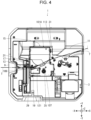
- the cartridge-side tape inlet 115 is provided on a surface of the cartridge case 103 in a +X direction, and is formed in a substantially rectangular shape elongated in a Z-axis direction. As illustrated in FIG. 4 , the cartridge-side tape inlet 115 introduces a tape T, which is a printing medium, from an outside of the cartridge case 103 into the cartridge case 103. That is, the tape T is introduced into the cartridge case 103 from the outside of the cartridge case 103 through the cartridge-side tape inlet 115 in a posture in which a width direction of the tape T is the Z-axis direction.
- the cartridge-side tape outlet 117 is provided on a surface of the cartridge case 103 in the -X direction, and is formed in a substantially rectangular shape elongated in the Z-axis direction.
- the cartridge-side tape outlet 117 discharges the tape T introduced into the cartridge case 103 to the outside of the cartridge case 103. That is, the tape T is discharged from the inside of the cartridge case 103 through the cartridge-side tape outlet 117 to the outside of the cartridge case 103 in a posture in which the width direction of the tape T is the Z-axis direction.
- the tape path 119 is a path from the cartridge-side tape inlet 115 to the cartridge-side tape outlet 117.
- the tape T introduced into the cartridge case 103 from the cartridge-side tape inlet 115 passes through the tape path 119, and is discharged from the cartridge-side tape outlet 117 to the outside of the cartridge case 103.
- the head insertion hole 121 is provided to penetrate through the cartridge case 103 in the Z-axis direction. As illustrated in FIG. 4 , a thermal head 17 and a head cover 19 provided in the tape printing apparatus 1 are inserted into the head insertion hole 121.
- the ribbon roll 105 includes an ink ribbon 123 and a feeding core 125 around which the ink ribbon 123 is wound.
- the ink ribbon 123 fed from the feeding core 125 is wound around the winding core 107.
- the platen roller 109 pinches the tape T and the ink ribbon 123 between the platen roller 109 and the thermal head 17 provided in the tape printing apparatus 1, and feeds the pinched tape T.
- the circuit substrate 113 is provided on the surface of the cartridge case 103 in the +X direction. Various types of information such as the remaining amount of the ink ribbon 123 is stored in the circuit substrate 113 in a rewritable manner.
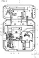
- the tape printing apparatus 1 in which the ribbon cartridge 101A is mounted will be described with reference to FIGS. 3 and 4 .
- the tape printing apparatus 1 includes an apparatus case 3 and a mounting portion cover 5.
- the apparatus case 3 is formed in a substantially rectangular shape.
- the apparatus case 3 is provided with an apparatus-side tape inlet 7, an apparatus-side tape outlet 9, a tape introduction path 11, a tape discharge path 13, and a cartridge mounting portion 15.
- the apparatus-side tape inlet 7 is provided on a surface of the apparatus case 3 in the +X direction, and is formed in a substantially rectangular shape elongated in the Z-axis direction.
- the apparatus-side tape inlet 7 introduces the tape T fed from a tape roll (not illustrated) set outside the apparatus case 3 into the apparatus case 3. That is, the tape T is introduced into the apparatus case 3 through the apparatus-side tape inlet 7 in a posture in which the width direction of the tape T is the Z-axis direction.
- the apparatus-side tape outlet 9 is provided on a surface of the apparatus case 3 in the - X direction, and is formed in a substantially rectangular shape elongated in the Z-axis direction.
- the apparatus-side tape outlet 9 discharges the tape T introduced into the apparatus case 3 to an outside of the apparatus case 3. That is, the tape T is discharged to the outside of the apparatus case 3 through the apparatus-side tape outlet 9 in a posture in which the width direction of the tape T is the Z-axis direction.
- the tape introduction path 11 is a path from the apparatus-side tape inlet 7 to the cartridge mounting portion 15.
- the tape T introduced from the apparatus-side tape inlet 7 into the apparatus case 3 is fed to the ribbon cartridge 101A mounted on the cartridge mounting portion 15, through the tape introduction path 11.
- the tape discharge path 13 is a path from the cartridge mounting portion 15 to the apparatus-side tape outlet 9.
- the tape T discharged from the ribbon cartridge 101A mounted on the cartridge mounting portion 15 is discharged from the apparatus-side tape outlet 9 to the outside of the apparatus case 3 through the tape discharge path 13.
- the cartridge mounting portion 15 is a recess portion that is opened in the +Z direction.
- the ribbon cartridge 101A is detachably mounted in the cartridge mounting portion 15.
- the apparatus-side tape inlet 7, the apparatus-side tape outlet 9, the tape introduction path 11, and the tape discharge path 13 are open in the +Z direction, in the same manner as the cartridge mounting portion 15. Therefore, when mounting the ribbon cartridge 101A in which the tape T is introduced in advance into the cartridge mounting portion 15, a user can insert the tape T projecting from the ribbon cartridge 101A into the apparatus-side tape inlet 7, the apparatus-side tape outlet 9, the tape introduction path 11, and the tape discharge path 13 from the +Z direction.
- the mounting portion cover 5 is rotatably attached to an end portion of the apparatus case 3 in the +Y direction.
- the mounting portion cover 5 opens and closes the apparatus-side tape inlet 7, the apparatus-side tape outlet 9, the tape introduction path 11, the tape discharge path 13, and the cartridge mounting portion 15 in the +Z direction.
- the mounting portion cover 5 is not illustrated.
- the cartridge mounting portion 15 is provided with the thermal head 17 and the head cover 19.
- the thermal head 17 includes a heat generating element (not illustrated), and performs printing on the tape T.
- the head cover 19 partially covers the thermal head 17.
- a platen shaft 21, a feeding shaft 23, and a winding shaft 25 project in the +Z direction.
- the platen shaft 21, the feeding shaft 23, and the winding shaft 25 are inserted into the platen roller 109, the feeding core 125, and the winding core 107, respectively. Therefore, rotation of a feed motor (not illustrated) can be transmitted to the platen roller 109, the feeding core 125, and the winding core 107.
- an entry projection 27 projects from the bottom surface of the cartridge mounting portion 15 in the +Z direction.
- the entry projection 27 enters the cartridge case 103 from a projection insertion hole 127 illustrated in FIG. 2 provided in the cartridge case 103.
- the thermal head 17 When the mounting portion cover 5 is closed after the ribbon cartridge 101A is mounted on the cartridge mounting portion 15, the thermal head 17 is moved toward the platen roller 109 by a head moving mechanism (not illustrated). Therefore, the tape T and the ink ribbon 123 are pinched between the thermal head 17 and the platen roller 109. When the platen roller 109 and the winding shaft 25 are rotated in this state, the tape T and the ink ribbon 123 are fed. At this time, the thermal head 17 generates heat based on print data received from an external apparatus such as a personal computer, and therefore, an ink of the ink ribbon 123 is transferred to the tape T, and a printing image is printed on the tape T.
- a cutter 29 is provided between the cartridge mounting portion 15 and the apparatus-side tape outlet 9.
- the cutter 29 cuts the tape T by using a cutter motor (not illustrated) as a driving source. Therefore, a printed portion of the tape T is cut away.
- a substrate connecting portion 31 is provided on an inner surface of the cartridge mounting portion 15.
- the substrate connecting portion 31 comes into contact with the circuit substrate 113 attached to the cartridge case 103. Therefore, the circuit substrate 113 and a control portion (not illustrated) included in the tape printing apparatus 1 are electrically connected to each other, via the substrate connecting portion 31.
- the control portion reads various types of information stored in the circuit substrate 113, and writes various types of information in the circuit substrate 113 via the substrate connecting portion 31.
- the cartridge case 103 will be described with reference to FIG. 1 and FIG. 2 .
- the cartridge case 103 includes a first case portion 129, and a second case portion 131 made of a member different from a member of the first case portion 129.
- the second case portion 131 is located in the +Z direction with respect to the first case portion 129.
- the ribbon cartridge 101A is mounted on the cartridge mounting portion 15 such that the first case portion 129 faces the bottom surface of the cartridge mounting portion 15.
- the second case portion 131 includes a second A case portion 133, a second B case portion 135, and a second C case portion 137.
- the second A case portion 133, the second B case portion 135, and the second C case portion 137 are made of members different from each other. That is, the second case portion 131 is made of three members of the second A case portion 133, the second B case portion 135, and the second C case portion 137.
- the first case portion 129 is made of a non- transmissive resin, and all of the second A case portion 133, the second B case portion 135, and the second C case portion 137 forming the second case portion 131 are made of a transmissive resin. Meanwhile, the material of each case portion is not limited thereto.
- the first case portion 129 and the second A case portion 133 form an outer shell of a tape presser accommodating portion 139.
- the tape pressing portion 111 is accommodated in the tape presser accommodating portion 139.
- the first case portion 129 and the second B case portion 135 form an outer shell of an ink ribbon accommodating portion 141.
- the ribbon roll 105 and the winding core 107 are accommodated in the ink ribbon accommodating portion 141.
- the first case portion 129 and the second C case portion 137 form an outer shell of a platen roller accommodating portion 143.
- the platen roller 109 is accommodated in the platen roller accommodating portion 143.
- the first case portion 129 will be described with reference to FIG. 2 .
- the first case portion 129 includes a first base wall portion 145 formed in a plate shape parallel to an XY plane and a first side wall portion 147 projecting from a peripheral edge portion of the first base wall portion 145 in the +Z direction.
- the first side wall portion 147 includes a first introduction-side side wall portion 149, a first discharge-side side wall portion 151, a first pressing-side side wall portion 153, and a first ribbon-side side wall portion 155.
- the first introduction-side side wall portion 149 is a wall portion located in the first side wall portion 147 in the +X direction.
- the first discharge-side side wall portion 151 is a wall portion located in the first side wall portion 147 in the -X direction.
- the first pressing-side side wall portion 153 is a wall portion located in the first side wall portion 147 in the +Y direction.
- the first ribbon-side side wall portion 155 is a wall portion located in the first side wall portion 147 in the -Y direction.
- the first side wall portion 147 is provided with a first inlet portion 157, a side wall projection portion 161, and a substrate attaching portion 163.
- the first inlet portion 157 is provided in the first introduction-side side wall portion 149, and is formed in a slit shape extending in the Z-axis direction.
- the first inlet portion 157 forms a part of the cartridge-side tape inlet 115.
- the side wall projection portion 161 is provided at an edge portion of the first inlet portion 157 in the -Y direction, and is formed in a substantially prismatic shape projecting in the +Z direction from an end surface of the first introduction-side side wall portion 149 in the +Z direction.
- the substrate attaching portion 163 is provided at an end portion of the first introduction-side side wall portion 149 in the +Y direction.
- the circuit substrate 113 is attached to the substrate attaching portion 163.
- the first base wall portion 145 is provided with a first head opening 165 located at a corner portion of the first base wall portion 145 in the -X direction and the -Y direction.
- the first head opening 165 is formed in a substantially rectangular shape, and forms an end portion of the head insertion hole 121 in the -Z direction.
- a cylindrical portion 167, a tape pressing support shaft 169, a holding portion 171, a first projection portion 173, a ribbon guide 175, a first tape guide 177, a second tape guide 179, and a support projection portion 181 are provided from the first base wall portion 145 in the +Z direction.
- the cylindrical portion 167, the tape pressing support shaft 169, the holding portion 171, and the first projection portion 173 are provided in the tape presser accommodating portion 139.
- the cylindrical portion 167 is provided at a substantially center portion of the tape presser accommodating portion 139 when viewed from the +Z direction.
- the cylindrical portion 167 is provided with the projection insertion hole 127 described above.
- the tape pressing support shaft 169 is provided in the +X direction and the +Y direction with respect to the cylindrical portion 167.
- the tape pressing support shaft 169 rotatably supports the tape pressing portion 111.
- the holding portion 171 is provided at an end portion of the first base wall portion 145 in the +Y direction.
- the holding portion 171 holds the tape pressing portion 111 at a position separated from the first tape guide 177.
- the first projection portion 173 is formed in a substantially arc shape centered on the tape pressing support shaft 169 when viewed from the +Z direction.
- the ribbon guide 175 is provided at a peripheral edge portion of the first head opening 165.
- the ribbon guide 175 is formed in a substantially square tubular shape, and forms a peripheral wall of the head insertion hole 121.
- the ribbon guide 175 guides the feed of the ink ribbon 123 such that the ink ribbon 123 fed from the ribbon roll 105 revolves around the head insertion hole 121.
- the first tape guide 177 and the second tape guide 179 are provided between the tape presser accommodating portion 139 and the ink ribbon accommodating portion 141.
- the first tape guide 177 extends between the first inlet portion 157 and the first head opening 165 in an oblique direction between the -X direction and the -Y direction.
- the second tape guide 179 is provided in the +Y direction with respect to the first tape guide 177.
- the second tape guide 179 is provided with a guide base portion 183 and three guide projection portions 185.
- the guide base portion 183 is provided substantially parallel to the first tape guide 177 from the first inlet portion 157 to the path intermediate portion 187.
- the path intermediate portion 187 means an intermediate point between the first inlet portion 157 and the first head opening 165.
- the three guide projection portions 185 project from the guide base portion 183 toward the first tape guide 177.
- the tape T introduced from the cartridge-side tape inlet 115 passes between the first tape guide 177 and the second tape guide 179, and more specifically, is fed to the platen roller 109 through a space between the first tape guide 177 and the three guide projection portions 185.
- the first tape guide 177 and the second tape guide 179 form a side wall of the tape path 119. That is, the first tape guide 177 and the second tape guide 179 guide the tape T introduced from the cartridge-side tape inlet 115 in a posture in which the width direction of the tape T is the Z-axis direction, in the thickness direction of the tape T.
- a surface of each guide projection portion 185 in the +Z direction is formed to be an inclined surface such that a tip portion, that is, an end portion on the first tape guide 177 side is located in the -Z direction with respect to a base end portion, that is, an end portion on the guide base portion 183 side. Therefore, when the user inserts the tape T into the tape path 119 from the +Z direction in a state in which the tape path 119 is opened in the +Z direction, even when an end portion of the tape T in the -Z direction hits a surface of the guide projection portion 185 in the +Z direction, the tape T is guided between the first tape guide 177 and the three guide projection portions 185. Therefore, when the user inserts the tape T into the tape path 119 from the +Z direction, the tape T can be prevented from being caught on the guide projection portion 185.
- the guide base portion 183 of the second tape guide 179 is provided between the first inlet portion 157 and the path intermediate portion 187. Therefore, a portion of the first tape guide 177, which is on the first inlet portion 157 side with respect to the path intermediate portion 187 faces the second tape guide 179. Meanwhile, a portion of the first tape guide 177, which is on the portion on the first head opening 165 side with respect to the path intermediate portion 187 does not face the second tape guide 179, but faces the tape pressing portion 111. That is, the first tape guide 177 also functions as a receiver of the tape pressing portion 111.
- the support projection portion 181 is provided in the vicinity of the platen roller 109.
- the support projection portion 181 is engaged with the second C case portion 137, and supports the second C case portion 137.
- the first case portion 129 is provided with three third engagement receiving portions 189, five first B engagement holes 191, and four first C engagement holes 193.
- the three engagement receiving portions 189 are provided one by one at the first introduction-side side wall portion 149, the first discharge-side side wall portion 151, and the first pressing-side side wall portion 153, corresponding to positions at which the second A case portion 133 is combined with the first case portion 129.
- the three engagement receiving portions 189 are engaged with three second A engagement projection portions 219 provided in the second A case portion 133 illustrated in FIG. 6 . Therefore, the second A case portion 133 is detachably combined with the first case portion 129.
- the five first B engagement holes 191 are provided corresponding to positions at which the second B case portion 135 is combined with the first case portion 129.
- four first B engagement holes 191 are provided in the first side wall portion 147 and one first B engagement hole 191 is provided in the ribbon guide 175.
- one first B engagement hole 191 is provided on an end surface of the side wall projection portion 161 in the +Z direction.
- the five first B engagement holes 191 extend in the Z-axis direction.
- five second B engagement pins 235 provided in the second B case portion 135 are press-fitted into the five first B engagement holes 191 from the +Z direction.
- the second B case portion 135 is combined with the first case portion 129.
- the second B engagement pin 235 and the first B engagement hole 191 into which the second B engagement pin 235 is press-fitted are referred to as a case engagement portion 195.
- the first case portion 129 and the second B case portion 135 are combined by five case engagement portions 195.
- the case engagement portion 195 constituting the first B engagement hole 191 provided in the side wall projection portion 161 and the second B engagement pin 235 press-fitted to the first B engagement hole 191 is provided at a position at which a distance D from the cartridge-side tape inlet 115 is smaller than a dimension W of the cartridge-side tape inlet 115 in a lateral direction of the cartridge-side tape inlet 115, that is, the Y-axis direction.
- the distance D between the case engagement portion 195 and the cartridge-side tape inlet 115 means a dimension between a center of the case engagement portion 195 in the Y-axis direction and an end portion of the cartridge-side tape inlet 115 in the -Y direction, that is, a second B introduction edge portion 237, which will be described below.
- the case engagement portion 195 provided at the position at which the distance D from the cartridge-side tape inlet 115 is smaller than the dimension W of the cartridge-side tape inlet 115 is the case engagement portion 195 constituting the first B engagement hole 191 provided on the side wall projection portion 161 and the second B engagement pin 235 press-fitted to the first B engagement hole 191.
- the present embodiment is not limited thereto.
- the case engagement portion 195 provided at the position at which the distance D from the cartridge-side tape inlet 115 is smaller than the dimension W of the cartridge-side tape inlet 115 may be the case engagement portion 195 constituting the first B engagement hole 191 provided on the first side wall portion 147 other than the side wall projection portion 161 and the second B engagement pin 235 press-fitted to the first B engagement hole 191.
- the four first C engagement holes 193 are provided corresponding to positions at which the second C case portion 137 is combined with the first case portion 129.
- three first C engagement holes 193 are provided at the first side wall portion 147 and one first C engagement hole 193 is provided at the support projection portion 181.
- the four first C engagement holes 193 extend in the Z-axis direction.
- four second C engagement pins 245 provided in the second C case portion 137 are press-fitted into the four first C engagement holes 193 from the +Z direction. Therefore, the second C case portion 137 is combined with the first case portion 129.
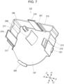
- the second A case portion 133 will be described with reference to FIGS. 6 and 7 .
- the second A case portion 133 includes a second A base wall portion 197 formed in a plate shape parallel to the XY plane and a second A side wall portion 199 projecting from a peripheral edge portion of the second A base wall portion 197 in the -Z direction.
- the first path 201 means a section of the tape path 119 from the cartridge-side tape inlet 115 to the middle of the tape path 119.
- the first path 201 corresponds to a section of the tape path 119, which is from the cartridge-side tape inlet 115 to a front of a case opening 203 provided between the second B case portion 135 and the second C case portion 137, that is, to an end portion of the case opening 203 on the cartridge-side tape inlet 115 side.
- the first path 201 has a length equal to or more than half a length of the tape path 119, more specifically, a length of approximately two thirds of the tape path 119.
- An overlap portion 205 is provided at an edge portion of the second A base wall portion 197 in the -Y direction.
- the overlap portion 205 is provided in the +Z direction with respect to the second A base wall portion 197.
- the overlap portion 205 overlaps with an outside of the second B case portion 135, that is, in the +Z direction.
- the overlap portion 205 is provided in the second A base wall portion 197, even when a force is applied to the second A base wall portion 197 from the outside, the overlap portion 205 is supported by the second B case portion 135 from the inside, that is, from the -Z direction, so that it is possible to prevent the second A base wall portion 197 from bending inward.
- a release portion 207 and a second projection portion 209 project from the second A base wall portion 197 in the -Z direction.
- the release portion 207 is formed in a substantially prismatic shape, and is engaged with the tape pressing portion 111 at a tip portion of the release portion 207 when the second A case portion 133 is mounted on the first case portion 129.
- the second projection portion 209 is formed in a substantially arc shape centered on the tape pressing support shaft 169 when viewed from the +Z direction.
- the second A side wall portion 199 includes a second A introduction-side side wall portion 211, a second A discharge-side side wall portion 213, and a second A pressing-side side wall portion 215.
- the second A introduction-side side wall portion 211 is a wall portion located in the second A side wall portion 199 in the +X direction.
- the second A discharge-side side wall portion 213 is a wall portion located in the second A side wall portion 199 in the -X direction.
- the second A pressing-side side wall portion 215 is a wall portion located in the second A side wall portion 199 in the +Y direction.
- a second A introduction edge portion 217 which is an end portion of the second A introduction-side side wall portion 211 in the -Y direction, forms an edge portion of the cartridge-side tape inlet 115 in the +Y direction. That is, as illustrated in FIG. 5 , the cartridge-side tape inlet 115 is provided between the second A introduction edge portion 217 of the second A case portion 133 and the second B introduction edge portion 237 of the second B case portion 135. In this manner, the cartridge-side tape inlet 115 can be configured by using a gap between the second A case portion 133 and the second B case portion 135.
- the second A side wall portion 199 is provided with the three second A engagement projection portions 219 and two finger hook portions 221.
- the three second A engagement projection portions 219 project one by one at the second A introduction-side side wall portion 211, the second A discharge-side side wall portion 213, and the second A pressing-side side wall portion 215 in the -Z direction.
- Each of the second A engagement projection portions 219 is formed to have a hook-shaped tip portion, and is engaged with the engagement receiving portion 189 provided in the first case portion 129.
- the three second A engagement projection portions 219 are engaged with the three engagement receiving portions 189, so that the second A case portion 133 is detachably combined with the first case portion 129.
- the second A case portion 133 can open and close the tape presser accommodating portion 139 and the first path 201 in the +Z direction. That is, the second A case portion 133 opens the tape presser accommodating portion 139 and the first path 201 in the +Z direction by being removed from the first case portion 129, and closes the tape presser accommodating portion 139 and the first path 201 in the +Z direction by being mounted on the first case portion 129.
- the user can operate the tape pressing portion 111 from the +Z direction.
- the user can insert the tape T from the +Z direction into the first path 201, that is, between the tape pressing portion 111 and the first tape guide 177.
- the second A case portion 133 closes the tape presser accommodating portion 139 and the first path 201 in the +Z direction, it is possible to prevent a foreign matter from entering the tape presser accommodating portion 139 and the first path 201.
- the ribbon cartridge 101A is to be mounted in the cartridge mounting portion 15, it is possible to prevent the movement of the tape T inserted in the tape path 119 in the Z-axis direction, that is, the width direction of the tape T. Therefore, the user can easily mount the ribbon cartridge 101A with the tape T inserted into the tape path 119 into the cartridge mounting portion 15.
- the second A case portion 133 closes the first path 201 in the +Z direction, which occupies half or more of the tape path 119, it is possible to more effectively prevent the movement of the tape T inserted into the tape path 119, in the width direction of the tape T.
- the second A case portion 133 closes the first path 201 in the +Z direction, it is preferable that there is almost no gap between the second A case portion 133 and the second B case portion 135.
- the second A case portion 133 closes not only a part of the first path 201 in a width direction of the first path 201, that is, in the thickness direction of the tape T inserted into the first path 201 but also an entirety of the first path 201.
- not only the first path 201 in the +Z direction including the cartridge-side tape inlet 115 but also a part of the cartridge-side tape outlet 117 in the +Z direction is closed by the outlet covering portion 234 illustrated in FIG. 8 , which is provided in the second B case portion 135.
- one finger hook portion 221 projects in the +X direction from an end portion of the second A introduction-side side wall portion 211 in the -Y direction, and the other finger hook portion 221 projects in the -X direction from an end portion of the second A discharge-side side wall portion 213 in the -Y direction.
- the two finger hook portions 221 are portions on which the user hooks a finger when the user removes the second A case portion 133 from the first case portion 129.
- the finger hook portion 221 is not limited to the configuration in which the finger hook portion 221 projects from the second A side wall portion 199, and may be a recess portion or may have a configuration in which a partial surface of the second A side wall portion 199 is roughened to make it difficult for the finger to slip.
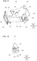
- the second B case portion 135 will be described with reference to FIG. 9 .
- the second B case portion 135 includes a second B base wall portion 223 formed in a plate shape parallel to the XY plane and a second B side wall portion 225 projecting from a peripheral edge portion of the second B base wall portion 223 in the -Z direction.
- the second B base wall portion 223 is provided substantially flush with the second A base wall portion 197 when the second A case portion 133 is mounted on the first case portion 129, and the overlap portion 205 overlaps with the second B base wall portion 223 in the +Z direction.
- the second B base wall portion 223 is provided with a second head opening 227 located at a corner portion of the second B base wall portion 223 in the -X direction and the -Y direction.
- the second head opening 227 is formed in a substantially rectangular shape, and forms an end portion of the head insertion hole 121 in the +Z direction.
- the case opening 203 is provided between the second B base wall portion 223 and a second C base wall portion 241 of the second C case portion 137.
- the case opening 203 is located in the +Z direction with respect to the tape path 119.
- the case opening 203 is a location through which the tape T passes when the tape T is inserted into the tape path 119 in the -Z direction.
- a gap between the second B case portion 135 and the second C case portion 137 can be used to form the case opening 203 through which the tape T passes when the tape T is inserted into the tape path 119.
- an end portion of the case opening 203 in the -X direction and the -Y direction is connected to the second head opening 227.
- the second B side wall portion 225 includes a second B introduction-side side wall portion 229, a second B discharge-side side wall portion 231, and a second B ribbon-side side wall portion 233.
- the second B introduction-side side wall portion 229 is a wall portion located in the second B side wall portion 225 in the +X direction.
- the second B discharge-side side wall portion 231 is a wall portion located in the second B side wall portion 225 in the -X direction.
- the second B ribbon-side side wall portion 233 is a wall portion located in the second B side wall portion 225 in the -Y direction.
- the second B case portion 135 is provided with the five second B engagement pins 235.
- the five second B engagement pins 235 four second B engagement pins 235 project in the -Z direction from an end surface of the second B side wall portion 225 in the -Z direction, and one second B engagement pin 235 is located near the second head opening 227 and projects from the second B base wall portion 223 in the -Z direction.
- the five second B engagement pins 235 are press-fitted into the five first B engagement holes 191 provided in the first case portion 129, from the +Z direction. Therefore, the second B case portion 135 is combined with the first case portion 129.
- the second B introduction edge portion 237 which is an end portion of the second B introduction-side side wall portion 229 in the +Y direction, forms an edge portion of the cartridge-side tape inlet 115 in the -Y direction. That is, as described above, the cartridge-side tape inlet 115 is provided between the second B introduction edge portion 237 of the second B case portion 135 and the second A introduction edge portion 217 of the second A case portion 133.
- a second B discharge edge portion 239 which is an end portion of the second B discharge-side side wall portion 231 in the +Y direction, forms an edge portion of the cartridge-side tape outlet 117 in the -Y direction. That is, as illustrated in FIG. 8 , the cartridge-side tape outlet 117 is provided between the second B discharge edge portion 239 of the second B case portion 135 and a second C discharge edge portion 247 of the second C case portion 137.
- the second C case portion 137 will be described with reference to FIG. 10 .
- the second C case portion 137 includes a second C base wall portion 241 formed in a plate shape parallel to the XY plane and a second C side wall portion 243 projecting from a peripheral edge portion of the second C base wall portion 241 in the -Z direction.
- the second C base wall portion 241 is provided substantially flush with the second A base wall portion 197 and the second C base wall portion 241 when the second A case portion 133 is mounted on the first case portion 129.
- the case opening 203 is provided between the second C base wall portion 241 and the second B base wall portion 223.
- the second C case portion 137 is provided with the four second C engagement pins 245.
- the four second C engagement pins 245 three second C engagement pins 245 project in the -Z direction from an end surface of the second C side wall portion 243 in the -Z direction, and one second C engagement pin 245 projects in the -Z direction from the second C base wall portion 241.
- the four second C engagement pins 245 are press-fitted into the four first C engagement holes 193 provided in the first case portion 129, from the +Z direction. Therefore, the second C case portion 137 is combined with the first case portion 129.
- the second C discharge edge portion 247 which is an end portion of the second C side wall portion 243 in the -Y direction, forms an edge portion of the cartridge-side tape outlet 117 in the +Y direction. That is, as described above, the cartridge-side tape outlet 117 is provided between the second C discharge edge portion 247 of the second C case portion 137 and the second B discharge edge portion 239 of the second B case portion 135.
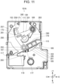
- the tape pressing portion 111 will be described with reference to FIGS. 11 and 12 .
- the tape pressing portion 111 is accommodated in the tape presser accommodating portion 139 to be movable between a separation position and s pressing position.
- the pressing position of the tape pressing portion 111 means a position at which the tape pressing portion 111 presses the tape T inserted into the tape path 119 against the first tape guide 177.
- the separation position of the tape pressing portion 111 means a position at which the tape pressing portion 111 is separated from the tape T inserted into the tape path 119.
- An elastic member 249 is accommodated in the tape presser accommodating portion 139 together with the tape pressing portion 111.
- the elastic member 249 applies a force to the tape pressing portion 111 in a direction in which the tape pressing portion 111 faces the pressing position, that is, to the tape pressing portion 111 counterclockwise when viewed from the +Z direction. Therefore, the tape pressing portion 111 can appropriately press the tape T by the elastic force of the elastic member 249.
- a torsion coil spring can be used as the elastic member 249.
- the elastic member 249 is provided at the tape pressing support shaft 169, one end portion of the elastic member 249 is latched to the tape pressing portion 111, and the other end portion of the elastic member 249 is latched to the first case portion 129.
- the tape pressing portion 111 includes an arm portion 251, a tape contact portion 253, a pressing projection portion 255, an engagement support portion 257, and a pressing engagement portion 259.
- the arm portion 251 is rotatably supported by the tape pressing support shaft 169 provided in the first case portion 129.
- the rotation of the arm portion 251 is guided by a surface of the arm portion 251 in the -Z direction being slid with the first projection portion 173.
- the rotation of the arm portion 251 is guided by a surface of the arm portion 251 in the +Z direction being slid with the second projection portion 209. Therefore, blurring of the arm portion 251 in the Z-axis direction is prevented when the arm portion 251 is rotated, and the arm portion 251 can be smoothly rotated.
- the arm portion 251 is formed in a shape bent in a substantially "L" shape when viewed from the +Z direction.
- a support shaft insertion portion 263 that is formed in a substantially disc shape is provided at an end portion of the arm portion 251 in the +X direction with respect to a bent portion 261.
- the tape pressing support shaft 169 is inserted through the support shaft insertion portion 263.
- the tape contact portion 253 is provided at an end portion of the arm portion 251 in the -Y direction with respect to the bent portion 261.
- the tape contact portion 253 is formed in a substantially cylindrical shape, and comes into contact with the tape T when the tape pressing portion 111 is located at the pressing position. That is, when the tape pressing portion 111 is located at the pressing position, the tape T inserted into the tape path 119 is pinched between the tape contact portion 253 and the first tape guide 177.
- the pressing projection portion 255 projects from the vicinity of the bent portion 261 of the arm portion 251 in the +Z direction.
- the pressing projection portion 255 is a portion on which the user hooks a finger when moving the tape pressing portion 111.
- the engagement support portion 257 projects in a substantially columnar shape from the vicinity of the bent portion 261 of the arm portion 251 toward a side opposite to the tape contact portion 253. At a tip of the engagement support portion 257, the pressing engagement portion 259 is provided.
- the pressing engagement portion 259 is provided at the tip of the engagement support portion 257.
- the pressing engagement portion 259 is engaged with the holding portion 171 provided in the first case portion 129 from a side opposite to the tape pressing support shaft 169 with respect to the holding portion 171, that is, from the -X direction to enter between the holding portion 171 and the first pressing-side side wall portion 153. Therefore, the movement of the tape pressing portion 111 is blocked against the elastic force of the elastic member 249. That is, the tape pressing portion 111 is held at the separation position by engaging the pressing engagement portion 259 with the holding portion 171.
- a release inclined surface 265 is provided on a surface of the pressing engagement portion 259 in the +Z direction.
- the release inclined surface 265 is inclined such that an end portion of the release inclined surface 265 in the +X direction is located in the -Z direction with respect to an end portion of the release inclined surface 265 in the -X direction.
- FIG. 11 A procedure in which a user inserts the tape T into the tape path 119 will be described with reference to FIGS. 11 to 15 .
- the user detaches the second A case portion 133 from the first case portion 129, and opens the tape presser accommodating portion 139 and the first path 201 in the +Z direction.
- the user can easily move the second A case portion 133 in the +Z direction with respect to the first case portion 129 by using the finger hook portion 221, and the second A case portion 133 can be easily detached from the first case portion 129.
- the user moves the tape pressing portion 111 to a separation position against the elastic force of the elastic member 249. At this time, the user can easily move the tape pressing portion 111 to the separation position by using the pressing projection portion 255.
- the pressing engagement portion 259 is engaged with the holding portion 171, so that the tape pressing portion 111 is held at the separation position. Therefore, when the user inserts the tape T into the tape path 119, it is not necessary to manually hold the tape pressing portion 111 such that the tape pressing portion 111 is located at the separation position, and operability can be improved.
- the user inserts the tape T pulled out from the tape roll from the +Z direction with respect to the tape path 119.
- the tape pressing portion 111 is separated from the first tape guide 177, the user can easily insert the tape T between the tape pressing portion 111 and the first tape guide 177.
- the user mounts the second A case portion 133 on the first case portion 129.
- the release portion 207 provided in the second A case portion 133 is engaged with the pressing engagement portion 259. Therefore, the pressing engagement portion 259 is displaced from the holding portion 171, and the tape pressing portion 111 is moved to a pressing position by the elastic force of the elastic member 249.
- the tape T inserted into the tape path 119 is pressed against the first tape guide 177 by the tape pressing portion 111 that has moved to the pressing position.
- the user can release the holding of the tape pressing portion 111 by the holding portion 171, and can move the tape pressing portion 111 to the pressing position, without performing an operation for releasing the holding of the tape pressing portion 111 by the holding portion 171, apart from the operation of mounting the second A case portion 133 on the first case portion 129.
- the second A case portion 133 is transparently illustrated.
- the user inserts the tape T into the tape path 119, and then mounts the ribbon cartridge 101A in the cartridge mounting portion 15. At this time, since the tape T inserted into the tape path 119 is pressed by the tape pressing portion 111, the tape T is prevented from coming out of the tape path 119 through the cartridge-side tape inlet 115. Therefore, the user can easily perform the operation of mounting the ribbon cartridge 101A at the cartridge mounting portion 15.
- the entry projection 27 that has entered the tape presser accommodating portion 139 from the projection insertion hole 127 is engaged with the arm portion 251, so that the tape pressing portion 111 is rotated in a direction in which the tape pressing portion 111 is moved toward the separation position. Therefore, since the tape pressing portion 111 is separated from the tape T, it is possible to prevent the feeding of the tape T from being interrupted by the tape pressing portion 111. In this manner, even when the user does not operate the tape pressing portion 111, the tape pressing portion 111 can be automatically separated from the tape T only by mounting the ribbon cartridge 101A in the cartridge mounting portion 15.
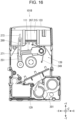
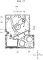
- a ribbon cartridge 101B which is a second embodiment of the ribbon cartridge, will be described with reference to FIGS. 16 and 17 .
- the second B case portion 135, the second C case portion 137, the ribbon roll 105, the winding core 107, and the platen roller 109 are not illustrated.
- the ribbon cartridge 101B is different from the ribbon cartridge 101A in that a hinge portion 267 and a connecting portion 269 are provided.
- the hinge portion 267 has a rotation axis parallel to the X-axis direction, and connects an end portion of the first pressing-side side wall portion 153 in the +Z direction and an end portion of the second A pressing-side side wall portion 215 in the -Z direction such that the second A case portion 133 can be rotated with respect to the first case portion 129. That is, the second A case portion 133 is connected to the first case portion 129 via the hinge portion 267.
- the second A case portion 133 opens the tape presser accommodating portion 139 and the first path 201 in the +Z direction, by being rotated in a first rotation direction with respect to the first case portion 129 around the hinge portion 267, that is, in a counterclockwise direction when viewed from the -X direction.
- the second A case portion 133 closes the tape presser accommodating portion 139 and the first path 201 in the +Z direction, by being rotated in a direction opposite to the first rotation direction with respect to the first case portion 129 around the hinge portion 267, that is, in a clockwise direction when viewed from the -X direction.
- the second A case portion 133 may be provided with the two finger hook portions 221. Therefore, the user can easily perform an operation of rotating the second A case portion 133 with respect to the first case portion 129.
- the connecting portion 269 connects the tape pressing portion 111 and the second A case portion 133.
- a pressing-side connecting engagement portion 271 is provided on a surface of the arm portion 251 in the +Z direction, and a case-side connecting engagement portion 273 is provided at the second A pressing-side side wall portion 215.
- the pressing-side connecting engagement portion 271 is engaged with an end portion of the connecting portion 269 in the -Y direction, and the case-side connecting engagement portion 273 is engaged with an end portion of the connecting portion 269 in the +Y direction.
- the tape pressing portion 111 Since the tape pressing portion 111 is connected to the second A case portion 133 via the connecting portion 269, when the second A case portion 133 is rotated in the first rotation direction, in conjunction with the rotation of the second A case portion 133, the tape pressing portion 111 is moved to the separation position, as illustrated in FIG. 16 . Therefore, the user can move the tape pressing portion 111 to the separation position without performing an operation of moving the tape pressing portion 111 to the separation position, apart from the operation of rotating the second A case portion 133 with respect to the first case portion 129.
- the tape pressing portion 111 When the second A case portion 133 is rotated in a second rotation direction, as illustrated in FIG. 17 , the tape pressing portion 111 is moved to a pressing position in conjunction with the rotation of the second A case portion 133. Therefore, the user can move the tape pressing portion 111 to the pressing position without performing an operation of moving the tape pressing portion 111 to the pressing position, apart from the operation of rotating the second A case portion 133 with respect to the first case portion 129.
- the second A case portion 133 is applied with a force in the second rotation direction by the elastic force of the elastic member 249 via the tape pressing portion 111 and the connecting portion 269.
- the ribbon cartridge 101A and the ribbon cartridge 101B of the present embodiment include the ink ribbon 123 and the cartridge case 103 accommodating the ink ribbon 123, and can be mounted on the tape printing apparatus 1.
- the cartridge case 103 includes the first case portion 129, and the second case portion 131 provided in the +Z direction with respect to the first case portion 129.
- the cartridge case 103 is provided with a cartridge-side tape inlet 115, and a cartridge-side tape outlet 117.
- the cartridge-side tape inlet 115 is formed in a long shape in a direction parallel to the +Z direction, and introduces the tape T from the outside of the cartridge case 103 into the cartridge case 103.
- the cartridge-side tape outlet 117 discharges the tape T introduced into the cartridge case 103 to the outside of the cartridge case 103.
- the first case portion 129 and the second case portion 131 are combined by a plurality of case engagement portions 195.
- the case engagement portion 195 includes the second B engagement pin 235 provided in the second case portion 131 and the first B engagement hole 191 provided in the first case portion 129 and engaged with the second B engagement pin 235.
- the cartridge-side tape inlet 115 is provided at a position at which the distance D from one case engagement portion 195 among the plurality of case engagement portions 195 is smaller than the dimension W of the cartridge-side tape inlet 115 in the lateral direction of the cartridge-side tape inlet 115.
- the ribbon cartridge 101A may not include the tape pressing portion 111.
- another component may be accommodated in a space corresponding to the tape presser accommodating portion 139, and no component in particular may be accommodated. The same manner is applied to the ribbon cartridge 101B.
- the case engagement portion 195 is not limited to the configuration in which the engagement pin is provided in the second case portion 131 in the same manner as the second B engagement pin 235, and the engagement hole is provided in the first case portion 129 in the same manner as the first B engagement hole 191.
- the case engagement portion 195 may have a configuration in which an engagement pin is provided in the first case portion 129 and an engagement hole is provided in the second case portion 131.
- the plurality of case engagement portions 195 may have a configuration in which the case engagement portion 195 in which the engagement pin is provided in the second case portion 131 and the engagement hole is provided in the first case portion 129, and the case engagement portion 195 in which the engagement pin is provided in the first case portion 129, and the engagement hole is provided in the second case portion 131 are mixed.
- the second case portion 131 is not limited to the configuration including three members formed of different members from each other, that is, the second A case portion 133, the second B case portion 135, and the second C case portion 137.
- the second case portion 131 may be configured to include a single member, may be configured to include two members, or may be configured to include four or more members.
- the first path 201 is not limited to the section of the tape path 119 from the cartridge-side tape inlet 115 to the front of the case opening 203.
- the first path 201 may be a section of the tape path 119 from the cartridge-side tape inlet 115 to a point between the cartridge-side tape inlet 115 and the case opening 203. That is, in the second A case portion 133, the first path 201 may have a configuration in which a section of the tape path 119 from the cartridge-side tape inlet 115 to a point between the cartridge-side tape inlet 115 and the case opening 203 can be opened and closed in the +Z direction.
- a ribbon cartridge configured to be mounted on a tape printing apparatus including: an ink ribbon; and a cartridge case that accommodates the ink ribbon, in which the cartridge case includes a first case portion, and a second case portion provided in a first direction with respect to the first case portion, the cartridge case is provided with a tape inlet that is formed in a long shape in a direction parallel to the first direction, and introduces a tape from an outside of the cartridge case into the cartridge case, and a tape outlet that discharges the tape introduced into the cartridge case to the outside of the cartridge case, the first case portion and the second case portion are combined by a plurality of case engagement portions including an engagement projection portion provided at one of the first case portion and the second case portion and an engagement recess portion provided at another of the first case portion and the second case portion and engaged with the engagement projection portion, and the tape inlet is provided at a position at which a distance from one case engagement portion of the plurality of case engagement portions is smaller than a dimension of the tape inlet in a lateral direction of the tape in
- the cartridge-side tape inlet 115 is an example of the "tape inlet”.
- the second B engagement pin 235 is an example of the "engagement projection portion”.
- the first B engagement hole 191 is an example of the "engagement recess portion”.
- the +Z direction is an example of the "first direction”.
- the second case portion may include a second A case portion, and a second B case portion made of a member different from a member of the second A case portion, and the tape inlet may be provided between the second A case portion and the second B case portion.
- the tape inlet can be formed by using a gap between the second A case portion and the second B case portion.
- the second A case portion may be configured to open and close the tape inlet in the first direction.
- the second A case portion may be provided with two finger hook portions on which a user hooks fingers when the user operates the second A case portion such that the tape inlet is opened in the first direction.
- the user can easily perform an operation of opening the tape inlet in the first direction by using the two finger hook portions.
- the ribbon cartridge may further include: a tape pressing portion that presses the tape introduced into the cartridge case against the first case portion, in which the first case portion and the second A case portion may form an outer shell of a tape presser accommodating portion in which the tape pressing portion is accommodated, and the second A case portion may be configured to open and close the tape presser accommodating portion in the first direction.
- the tape presser accommodating portion by opening the tape presser accommodating portion in the first direction, the user can operate the tape pressing portion from the first direction.
- the tape presser accommodating portion is closed in the first direction, it is possible to prevent a foreign matter from entering the tape accommodating portion.
- the tape pressing portion may be movable between a pressing position for pressing the tape against the first case portion and a separation position spaced apart from the tape.
- the user can easily insert the tape between the tape pressing portion and the first case portion by moving the tape pressing portion to the separation position.
- the second A case portion may be detachably combined with the first case portion and may be detached from the first case portion to open the tape presser accommodating portion in the first direction.
- the user can open the tape presser accommodating portion in the first direction by detaching the second A case portion from the first case portion.
- the first case portion may be provided with a holding portion configured to hold the tape pressing portion at the separation position when the second A case portion is detached from the first case portion.
- the tape pressing portion can be held at the separation position by the holding portion. Therefore, the user does not need to manually hold the tape pressing portion such that the tape pressing portion is located at the separation position, and thus it is possible to improve operability.
- the second A case portion may be provided with a release portion that releases the holding of the tape pressing portion by the holding portion, by engaging with the tape pressing portion when the second A case portion is mounted on the first case portion.
- the user can release the holding of the tape pressing portion by the holding portion without performing an operation for releasing the holding of the tape pressing portion by the holding portion, apart from the operation of mounting the second A case portion on the first case portion.
- the tape pressing portion may be provided with a pressing projection portion on which a user hooks a finger when the user moves the tape pressing portion.
- the second A case portion may be connected to the first case portion via a hinge portion and may be rotated around the hinge portion with respect to the first case portion to open the tape presser accommodating portion in the first direction.
- the user can open the tape presser accommodating portion in the first direction by rotating the second A case portion around the hinge portion with respect to the first case portion.
- the ribbon cartridge may further include: a connecting portion that connects the tape pressing portion and the second A case portion, in which when the second A case portion is rotated in a direction in which the tape presser accommodating portion is opened in the first direction, the tape pressing portion may be moved to the separation position in conjunction with the rotation of the second A case portion, and when the second A case portion is rotated in a direction in which the tape presser accommodating portion is closed in the first direction, the tape pressing portion may be moved to the pressing position in conjunction with the rotation of the second A case portion.
- the user can move the tape pressing portion to the separation position without performing an operation of moving the tape pressing portion to the separation position, apart from the operation of rotating the second A case portion with respect to the first case portion.
- the user can move the tape pressing portion to the pressing position without performing an operation of moving the tape pressing portion to the pressing position, apart from the operation of rotating the second A case portion with respect to the first case portion.
- the ribbon cartridge may further include: an elastic member that applies a force to the tape pressing portion toward the pressing position.
- the tape pressing portion can appropriately press the tape by the elastic force of the elastic member.
- the first case portion may be provided with a tape pressing support shaft that rotatably supports the tape pressing portion between the pressing position and the separation position
- the tape pressing portion may include an arm portion rotatably supported by the tape pressing support shaft, and a tape contact portion that is provided at the arm portion, and comes into contact with the tape when the tape pressing portion is located at the pressing position.
- the first case portion may be provided with a first projection portion projecting in the first direction, and the arm portion may be slid with the first projection portion while rotating.
- the second A case portion may be provided with a second projection portion projecting in a second direction opposite to the first direction, and the arm portion may be slid with the second projection portion while rotating.
- the +Z direction is an example of the "second direction".
Landscapes
- Impression-Transfer Materials And Handling Thereof (AREA)
- Printers Characterized By Their Purpose (AREA)
Abstract
Description
- The present application is based on, and claims priority from
JP Application Serial Number 2023-003265, filed January 12, 2023 - The present disclosure relates to a ribbon cartridge that can be mounted on a tape printing apparatus.
- In the related art, as disclosed in
JP-A-2020-104326 - In the cartridge case provided with the tape inlet, a rigidity of the cartridge case is decreased, and thus, the cartridge case may bend or a part of the cartridge case may be deformed.
- According to an aspect of the present disclosure, there is provided a ribbon cartridge configured to be mounted on a tape printing apparatus including: an ink ribbon; and a cartridge case that accommodates the ink ribbon, in which the cartridge case includes a first case portion, and a second case portion provided in a first direction with respect to the first case portion, the cartridge case is provided with a tape inlet that is formed in a long shape in a direction parallel to the first direction, and introduces a tape from an outside of the cartridge case into the cartridge case, and a tape outlet that discharges the tape introduced into the cartridge case to the outside of the cartridge case, the first case portion and the second case portion are combined by a plurality of case engagement portions including an engagement projection portion provided at one of the first case portion and the second case portion and an engagement recess portion provided at another of the first case portion and the second case portion and engaged with the engagement projection portion, and the tape inlet is provided at a position at which a distance from one case engagement portion of the plurality of case engagement portions is smaller than a dimension of the tape inlet in a lateral direction of the tape inlet.
-
-
FIG. 1 is a perspective view of a ribbon cartridge. -
FIG. 2 is a perspective view of the ribbon cartridge illustrating a structure inside a cartridge case. -
FIG. 3 is a view of a tape printing apparatus in a state in which the ribbon cartridge is not mounted, as viewed from a +Z direction. -
FIG. 4 is a view of the tape printing apparatus in a state in which the ribbon cartridge is mounted, as viewed from the +Z direction. -
FIG. 5 is a view of the ribbon cartridge viewed from a +X direction. -
FIG. 6 is a perspective view of a second A case portion. -
FIG. 7 is a perspective view of the second A case portion viewed from an angle different from an angle ofFIG. 6 . -
FIG. 8 is a view of the ribbon cartridge viewed from a -X direction. -
FIG. 9 is a perspective view of a second B case portion. -
FIG. 10 is a perspective view of a second C case portion. -
FIG. 11 is a view of the ribbon cartridge in a state in which the second A case portion is removed from a first case portion and a tape pressing portion is located at a pressing position, as viewed from the +Z direction. -
FIG. 12 is a view of the ribbon cartridge in a state in which the second A case portion is removed from the first case portion and the tape pressing portion is located at a separation position, as viewed from the +Z direction. -
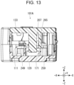
FIG. 13 is a cross-sectional diagram of the ribbon cartridge. -
FIG. 14 is a view of the ribbon cartridge in a state in which the second A case portion is removed from the first case portion and a tape is inserted into a tape path, as viewed from the +Z direction. -
FIG. 15 is a view of the ribbon cartridge in a state in which the tape is inserted into the tape path and the second A case portion is mounted on the first case portion, as viewed from the +Z direction. -
FIG. 16 is a cross-sectional diagram of the ribbon cartridge in a state in which the second A case portion opens a tape presser accommodating portion, as viewed from the +Z direction. -
FIG. 17 is a view of the ribbon cartridge in a state in which the second A case portion closes the tape presser accommodating portion, as viewed from the +Z direction. - Hereinafter, one embodiment of a ribbon cartridge will be described with reference to the accompanying drawings.
FIGS. 1 to 15 are views illustrating a first embodiment of the ribbon cartridge, andFIGS. 16 and17 are views illustrating a second embodiment of the ribbon cartridge. In the following, directions based on the XYZ orthogonal coordinate system illustrated in each drawing will be described. However, these directions are for convenience of explanation only and do not limit the following embodiments in any way. In addition, the number of each component is merely an example, and does not limit the following embodiments in any way. - A
ribbon cartridge 101A, which is a first embodiment of the ribbon cartridge, will be described with reference toFIGS. 1 and2 . Theribbon cartridge 101A includes acartridge case 103, aribbon roll 105, a windingcore 107, aplaten roller 109, atape pressing portion 111, and acircuit substrate 113. - The
cartridge case 103 accommodates theribbon roll 105, the windingcore 107, theplaten roller 109, and thetape pressing portion 111. Further, thecircuit substrate 113 is attached to thecartridge case 103. InFIG. 2 , in order to illustrate a structure inside thecartridge case 103, a part of thecartridge case 103, that is, asecond case portion 131, which will be described later, is not illustrated. - The
cartridge case 103 is provided with a cartridge-side tape inlet 115, a cartridge-side tape outlet 117, atape path 119, and ahead insertion hole 121. - The cartridge-
side tape inlet 115 is provided on a surface of thecartridge case 103 in a +X direction, and is formed in a substantially rectangular shape elongated in a Z-axis direction. As illustrated inFIG. 4 , the cartridge-side tape inlet 115 introduces a tape T, which is a printing medium, from an outside of thecartridge case 103 into thecartridge case 103. That is, the tape T is introduced into thecartridge case 103 from the outside of thecartridge case 103 through the cartridge-side tape inlet 115 in a posture in which a width direction of the tape T is the Z-axis direction. - The cartridge-
side tape outlet 117 is provided on a surface of thecartridge case 103 in the -X direction, and is formed in a substantially rectangular shape elongated in the Z-axis direction. The cartridge-side tape outlet 117 discharges the tape T introduced into thecartridge case 103 to the outside of thecartridge case 103. That is, the tape T is discharged from the inside of thecartridge case 103 through the cartridge-side tape outlet 117 to the outside of thecartridge case 103 in a posture in which the width direction of the tape T is the Z-axis direction. - The
tape path 119 is a path from the cartridge-side tape inlet 115 to the cartridge-side tape outlet 117. The tape T introduced into thecartridge case 103 from the cartridge-side tape inlet 115 passes through thetape path 119, and is discharged from the cartridge-side tape outlet 117 to the outside of thecartridge case 103. - The
head insertion hole 121 is provided to penetrate through thecartridge case 103 in the Z-axis direction. As illustrated inFIG. 4 , athermal head 17 and ahead cover 19 provided in thetape printing apparatus 1 are inserted into thehead insertion hole 121. - The
ribbon roll 105 includes anink ribbon 123 and a feedingcore 125 around which theink ribbon 123 is wound. Theink ribbon 123 fed from thefeeding core 125 is wound around the windingcore 107. - The
platen roller 109 pinches the tape T and theink ribbon 123 between theplaten roller 109 and thethermal head 17 provided in thetape printing apparatus 1, and feeds the pinched tape T. - The
circuit substrate 113 is provided on the surface of thecartridge case 103 in the +X direction. Various types of information such as the remaining amount of theink ribbon 123 is stored in thecircuit substrate 113 in a rewritable manner. - The
tape printing apparatus 1 in which theribbon cartridge 101A is mounted will be described with reference toFIGS. 3 and4 . Thetape printing apparatus 1 includes anapparatus case 3 and amounting portion cover 5. Theapparatus case 3 is formed in a substantially rectangular shape. - The
apparatus case 3 is provided with an apparatus-side tape inlet 7, an apparatus-side tape outlet 9, atape introduction path 11, atape discharge path 13, and acartridge mounting portion 15. - The apparatus-
side tape inlet 7 is provided on a surface of theapparatus case 3 in the +X direction, and is formed in a substantially rectangular shape elongated in the Z-axis direction. The apparatus-side tape inlet 7 introduces the tape T fed from a tape roll (not illustrated) set outside theapparatus case 3 into theapparatus case 3. That is, the tape T is introduced into theapparatus case 3 through the apparatus-side tape inlet 7 in a posture in which the width direction of the tape T is the Z-axis direction. - The apparatus-
side tape outlet 9 is provided on a surface of theapparatus case 3 in the - X direction, and is formed in a substantially rectangular shape elongated in the Z-axis direction. The apparatus-side tape outlet 9 discharges the tape T introduced into theapparatus case 3 to an outside of theapparatus case 3. That is, the tape T is discharged to the outside of theapparatus case 3 through the apparatus-side tape outlet 9 in a posture in which the width direction of the tape T is the Z-axis direction. - The
tape introduction path 11 is a path from the apparatus-side tape inlet 7 to thecartridge mounting portion 15. The tape T introduced from the apparatus-side tape inlet 7 into theapparatus case 3 is fed to theribbon cartridge 101A mounted on thecartridge mounting portion 15, through thetape introduction path 11. - The
tape discharge path 13 is a path from thecartridge mounting portion 15 to the apparatus-side tape outlet 9. The tape T discharged from theribbon cartridge 101A mounted on thecartridge mounting portion 15 is discharged from the apparatus-side tape outlet 9 to the outside of theapparatus case 3 through thetape discharge path 13. - The
cartridge mounting portion 15 is a recess portion that is opened in the +Z direction. Theribbon cartridge 101A is detachably mounted in thecartridge mounting portion 15. - The apparatus-
side tape inlet 7, the apparatus-side tape outlet 9, thetape introduction path 11, and thetape discharge path 13 are open in the +Z direction, in the same manner as thecartridge mounting portion 15. Therefore, when mounting theribbon cartridge 101A in which the tape T is introduced in advance into thecartridge mounting portion 15, a user can insert the tape T projecting from theribbon cartridge 101A into the apparatus-side tape inlet 7, the apparatus-side tape outlet 9, thetape introduction path 11, and thetape discharge path 13 from the +Z direction. - The mounting
portion cover 5 is rotatably attached to an end portion of theapparatus case 3 in the +Y direction. The mountingportion cover 5 opens and closes the apparatus-side tape inlet 7, the apparatus-side tape outlet 9, thetape introduction path 11, thetape discharge path 13, and thecartridge mounting portion 15 in the +Z direction. InFIG. 4 , the mountingportion cover 5 is not illustrated. - The
cartridge mounting portion 15 is provided with thethermal head 17 and thehead cover 19. Thethermal head 17 includes a heat generating element (not illustrated), and performs printing on the tape T. The head cover 19 partially covers thethermal head 17. When theribbon cartridge 101A is mounted on thecartridge mounting portion 15, thethermal head 17 and thehead cover 19 are inserted into thehead insertion hole 121. - From a bottom surface of the
cartridge mounting portion 15, aplaten shaft 21, a feedingshaft 23, and a windingshaft 25 project in the +Z direction. When theribbon cartridge 101A is mounted on thecartridge mounting portion 15, theplaten shaft 21, the feedingshaft 23, and the windingshaft 25 are inserted into theplaten roller 109, thefeeding core 125, and the windingcore 107, respectively. Therefore, rotation of a feed motor (not illustrated) can be transmitted to theplaten roller 109, thefeeding core 125, and the windingcore 107. - Further, an
entry projection 27 projects from the bottom surface of thecartridge mounting portion 15 in the +Z direction. When theribbon cartridge 101A is mounted in thecartridge mounting portion 15, theentry projection 27 enters thecartridge case 103 from aprojection insertion hole 127 illustrated inFIG. 2 provided in thecartridge case 103. - When the mounting
portion cover 5 is closed after theribbon cartridge 101A is mounted on thecartridge mounting portion 15, thethermal head 17 is moved toward theplaten roller 109 by a head moving mechanism (not illustrated). Therefore, the tape T and theink ribbon 123 are pinched between thethermal head 17 and theplaten roller 109. When theplaten roller 109 and the windingshaft 25 are rotated in this state, the tape T and theink ribbon 123 are fed. At this time, thethermal head 17 generates heat based on print data received from an external apparatus such as a personal computer, and therefore, an ink of theink ribbon 123 is transferred to the tape T, and a printing image is printed on the tape T. - A
cutter 29 is provided between thecartridge mounting portion 15 and the apparatus-side tape outlet 9. Thecutter 29 cuts the tape T by using a cutter motor (not illustrated) as a driving source. Therefore, a printed portion of the tape T is cut away. - A
substrate connecting portion 31 is provided on an inner surface of thecartridge mounting portion 15. When theribbon cartridge 101A is mounted on thecartridge mounting portion 15, thesubstrate connecting portion 31 comes into contact with thecircuit substrate 113 attached to thecartridge case 103. Therefore, thecircuit substrate 113 and a control portion (not illustrated) included in thetape printing apparatus 1 are electrically connected to each other, via thesubstrate connecting portion 31. The control portion reads various types of information stored in thecircuit substrate 113, and writes various types of information in thecircuit substrate 113 via thesubstrate connecting portion 31. - The
cartridge case 103 will be described with reference toFIG. 1 andFIG. 2 . Thecartridge case 103 includes afirst case portion 129, and asecond case portion 131 made of a member different from a member of thefirst case portion 129. Thesecond case portion 131 is located in the +Z direction with respect to thefirst case portion 129. Theribbon cartridge 101A is mounted on thecartridge mounting portion 15 such that thefirst case portion 129 faces the bottom surface of thecartridge mounting portion 15. - The
second case portion 131 includes a secondA case portion 133, a secondB case portion 135, and a secondC case portion 137. The secondA case portion 133, the secondB case portion 135, and the secondC case portion 137 are made of members different from each other. That is, thesecond case portion 131 is made of three members of the secondA case portion 133, the secondB case portion 135, and the secondC case portion 137. Thefirst case portion 129 is made of a non- transmissive resin, and all of the secondA case portion 133, the secondB case portion 135, and the secondC case portion 137 forming thesecond case portion 131 are made of a transmissive resin. Meanwhile, the material of each case portion is not limited thereto. - The
first case portion 129 and the secondA case portion 133 form an outer shell of a tapepresser accommodating portion 139. Thetape pressing portion 111 is accommodated in the tapepresser accommodating portion 139. Thefirst case portion 129 and the secondB case portion 135 form an outer shell of an inkribbon accommodating portion 141. Theribbon roll 105 and the windingcore 107 are accommodated in the inkribbon accommodating portion 141. Thefirst case portion 129 and the secondC case portion 137 form an outer shell of a platenroller accommodating portion 143. Theplaten roller 109 is accommodated in the platenroller accommodating portion 143. - The
first case portion 129 will be described with reference toFIG. 2 . Thefirst case portion 129 includes a first base wall portion 145 formed in a plate shape parallel to an XY plane and a firstside wall portion 147 projecting from a peripheral edge portion of the first base wall portion 145 in the +Z direction. - The first
side wall portion 147 includes a first introduction-sideside wall portion 149, a first discharge-sideside wall portion 151, a first pressing-sideside wall portion 153, and a first ribbon-sideside wall portion 155. The first introduction-sideside wall portion 149 is a wall portion located in the firstside wall portion 147 in the +X direction. The first discharge-sideside wall portion 151 is a wall portion located in the firstside wall portion 147 in the -X direction. The first pressing-sideside wall portion 153 is a wall portion located in the firstside wall portion 147 in the +Y direction. The first ribbon-sideside wall portion 155 is a wall portion located in the firstside wall portion 147 in the -Y direction. - The first
side wall portion 147 is provided with afirst inlet portion 157, a sidewall projection portion 161, and asubstrate attaching portion 163. - The
first inlet portion 157 is provided in the first introduction-sideside wall portion 149, and is formed in a slit shape extending in the Z-axis direction. Thefirst inlet portion 157 forms a part of the cartridge-side tape inlet 115. - The side
wall projection portion 161 is provided at an edge portion of thefirst inlet portion 157 in the -Y direction, and is formed in a substantially prismatic shape projecting in the +Z direction from an end surface of the first introduction-sideside wall portion 149 in the +Z direction. Thesubstrate attaching portion 163 is provided at an end portion of the first introduction-sideside wall portion 149 in the +Y direction. Thecircuit substrate 113 is attached to thesubstrate attaching portion 163. - The first base wall portion 145 is provided with a first head opening 165 located at a corner portion of the first base wall portion 145 in the -X direction and the -Y direction. The
first head opening 165 is formed in a substantially rectangular shape, and forms an end portion of thehead insertion hole 121 in the -Z direction. - A
cylindrical portion 167, a tape pressingsupport shaft 169, a holdingportion 171, afirst projection portion 173, aribbon guide 175, afirst tape guide 177, asecond tape guide 179, and asupport projection portion 181 are provided from the first base wall portion 145 in the +Z direction. - The
cylindrical portion 167, the tape pressingsupport shaft 169, the holdingportion 171, and thefirst projection portion 173 are provided in the tapepresser accommodating portion 139. Thecylindrical portion 167 is provided at a substantially center portion of the tapepresser accommodating portion 139 when viewed from the +Z direction. Thecylindrical portion 167 is provided with theprojection insertion hole 127 described above. When theribbon cartridge 101A is mounted in thecartridge mounting portion 15, theentry projection 27 provided in thecartridge mounting portion 15 enters the tapepresser accommodating portion 139 through theprojection insertion hole 127. The tape pressingsupport shaft 169 is provided in the +X direction and the +Y direction with respect to thecylindrical portion 167. The tape pressingsupport shaft 169 rotatably supports thetape pressing portion 111. The holdingportion 171 is provided at an end portion of the first base wall portion 145 in the +Y direction. The holdingportion 171 holds thetape pressing portion 111 at a position separated from thefirst tape guide 177. As illustrated inFIGS. 11 and12 , thefirst projection portion 173 is formed in a substantially arc shape centered on the tape pressingsupport shaft 169 when viewed from the +Z direction. - The
ribbon guide 175 is provided at a peripheral edge portion of thefirst head opening 165. Theribbon guide 175 is formed in a substantially square tubular shape, and forms a peripheral wall of thehead insertion hole 121. Theribbon guide 175 guides the feed of theink ribbon 123 such that theink ribbon 123 fed from theribbon roll 105 revolves around thehead insertion hole 121. - The
first tape guide 177 and thesecond tape guide 179 are provided between the tapepresser accommodating portion 139 and the inkribbon accommodating portion 141. Thefirst tape guide 177 extends between thefirst inlet portion 157 and the first head opening 165 in an oblique direction between the -X direction and the -Y direction. - As illustrated in
FIGS. 11 and12 , thesecond tape guide 179 is provided in the +Y direction with respect to thefirst tape guide 177. Thesecond tape guide 179 is provided with aguide base portion 183 and threeguide projection portions 185. Theguide base portion 183 is provided substantially parallel to thefirst tape guide 177 from thefirst inlet portion 157 to the pathintermediate portion 187. The pathintermediate portion 187 means an intermediate point between thefirst inlet portion 157 and thefirst head opening 165. The threeguide projection portions 185 project from theguide base portion 183 toward thefirst tape guide 177. - The tape T introduced from the cartridge-
side tape inlet 115 passes between thefirst tape guide 177 and thesecond tape guide 179, and more specifically, is fed to theplaten roller 109 through a space between thefirst tape guide 177 and the threeguide projection portions 185. Thefirst tape guide 177 and thesecond tape guide 179 form a side wall of thetape path 119. That is, thefirst tape guide 177 and thesecond tape guide 179 guide the tape T introduced from the cartridge-side tape inlet 115 in a posture in which the width direction of the tape T is the Z-axis direction, in the thickness direction of the tape T. - A surface of each
guide projection portion 185 in the +Z direction is formed to be an inclined surface such that a tip portion, that is, an end portion on thefirst tape guide 177 side is located in the -Z direction with respect to a base end portion, that is, an end portion on theguide base portion 183 side. Therefore, when the user inserts the tape T into thetape path 119 from the +Z direction in a state in which thetape path 119 is opened in the +Z direction, even when an end portion of the tape T in the -Z direction hits a surface of theguide projection portion 185 in the +Z direction, the tape T is guided between thefirst tape guide 177 and the threeguide projection portions 185. Therefore, when the user inserts the tape T into thetape path 119 from the +Z direction, the tape T can be prevented from being caught on theguide projection portion 185. - As described above, the
guide base portion 183 of thesecond tape guide 179 is provided between thefirst inlet portion 157 and the pathintermediate portion 187. Therefore, a portion of thefirst tape guide 177, which is on thefirst inlet portion 157 side with respect to the pathintermediate portion 187 faces thesecond tape guide 179. Meanwhile, a portion of thefirst tape guide 177, which is on the portion on the first head opening 165 side with respect to the pathintermediate portion 187 does not face thesecond tape guide 179, but faces thetape pressing portion 111. That is, thefirst tape guide 177 also functions as a receiver of thetape pressing portion 111. - The
support projection portion 181 is provided in the vicinity of theplaten roller 109. Thesupport projection portion 181 is engaged with the secondC case portion 137, and supports the secondC case portion 137. - The
first case portion 129 is provided with three thirdengagement receiving portions 189, five first B engagement holes 191, and four first C engagement holes 193. - The three
engagement receiving portions 189 are provided one by one at the first introduction-sideside wall portion 149, the first discharge-sideside wall portion 151, and the first pressing-sideside wall portion 153, corresponding to positions at which the secondA case portion 133 is combined with thefirst case portion 129. The threeengagement receiving portions 189 are engaged with three second Aengagement projection portions 219 provided in the secondA case portion 133 illustrated inFIG. 6 . Therefore, the secondA case portion 133 is detachably combined with thefirst case portion 129. - The five first B engagement holes 191 are provided corresponding to positions at which the second
B case portion 135 is combined with thefirst case portion 129. Among the five first B engagement holes 191, four first B engagement holes 191 are provided in the firstside wall portion 147 and one firstB engagement hole 191 is provided in theribbon guide 175. Among the four first B engagement holes 191 provided in the firstside wall portion 147, one firstB engagement hole 191 is provided on an end surface of the sidewall projection portion 161 in the +Z direction. The five first B engagement holes 191 extend in the Z-axis direction. As illustrated inFIG. 9 , five second B engagement pins 235 provided in the secondB case portion 135 are press-fitted into the five first B engagement holes 191 from the +Z direction. Therefore, the secondB case portion 135 is combined with thefirst case portion 129. The secondB engagement pin 235 and the firstB engagement hole 191 into which the secondB engagement pin 235 is press-fitted are referred to as acase engagement portion 195. Thefirst case portion 129 and the secondB case portion 135 are combined by fivecase engagement portions 195. - As illustrated in
FIG. 5 , among the fivecase engagement portions 195, thecase engagement portion 195 constituting the firstB engagement hole 191 provided in the sidewall projection portion 161 and the secondB engagement pin 235 press-fitted to the firstB engagement hole 191 is provided at a position at which a distance D from the cartridge-side tape inlet 115 is smaller than a dimension W of the cartridge-side tape inlet 115 in a lateral direction of the cartridge-side tape inlet 115, that is, the Y-axis direction. Therefore, unlike the present embodiment, even with thecase engagement portion 195 closest to the cartridge-side tape inlet 115, it is possible to prevent a decrease in rigidity of thecartridge case 103 due to the provision of the cartridge-side tape inlet 115, as compared to a configuration in which thecase engagement portion 195 is provided at a position at which the distance D from the cartridge-side tape inlet 115 is larger than the dimension W of the cartridge-side tape inlet 115. Here, the distance D between thecase engagement portion 195 and the cartridge-side tape inlet 115 means a dimension between a center of thecase engagement portion 195 in the Y-axis direction and an end portion of the cartridge-side tape inlet 115 in the -Y direction, that is, a second Bintroduction edge portion 237, which will be described below. - In the present embodiment, the
case engagement portion 195 provided at the position at which the distance D from the cartridge-side tape inlet 115 is smaller than the dimension W of the cartridge-side tape inlet 115 is thecase engagement portion 195 constituting the firstB engagement hole 191 provided on the sidewall projection portion 161 and the secondB engagement pin 235 press-fitted to the firstB engagement hole 191. Meanwhile, the present embodiment is not limited thereto. For example, thecase engagement portion 195 provided at the position at which the distance D from the cartridge-side tape inlet 115 is smaller than the dimension W of the cartridge-side tape inlet 115 may be thecase engagement portion 195 constituting the firstB engagement hole 191 provided on the firstside wall portion 147 other than the sidewall projection portion 161 and the secondB engagement pin 235 press-fitted to the firstB engagement hole 191. - The four first C engagement holes 193 are provided corresponding to positions at which the second
C case portion 137 is combined with thefirst case portion 129. Among the four first C engagement holes 193, three first C engagement holes 193 are provided at the firstside wall portion 147 and one firstC engagement hole 193 is provided at thesupport projection portion 181. The four first C engagement holes 193 extend in the Z-axis direction. As illustrated inFIG. 10 , four second C engagement pins 245 provided in the secondC case portion 137 are press-fitted into the four first C engagement holes 193 from the +Z direction. Therefore, the secondC case portion 137 is combined with thefirst case portion 129. - The second
A case portion 133 will be described with reference toFIGS. 6 and7 . The secondA case portion 133 includes a second Abase wall portion 197 formed in a plate shape parallel to the XY plane and a second Aside wall portion 199 projecting from a peripheral edge portion of the second Abase wall portion 197 in the -Z direction. - When the second
A case portion 133 is mounted on thefirst case portion 129, the second Abase wall portion 197 covers the tapepresser accommodating portion 139 and afirst path 201 in the +Z direction. Here, thefirst path 201 means a section of thetape path 119 from the cartridge-side tape inlet 115 to the middle of thetape path 119. In the present embodiment, as illustrated inFIGS. 11 and12 , thefirst path 201 corresponds to a section of thetape path 119, which is from the cartridge-side tape inlet 115 to a front of a case opening 203 provided between the secondB case portion 135 and the secondC case portion 137, that is, to an end portion of the case opening 203 on the cartridge-side tape inlet 115 side. Thefirst path 201 has a length equal to or more than half a length of thetape path 119, more specifically, a length of approximately two thirds of thetape path 119. - An
overlap portion 205 is provided at an edge portion of the second Abase wall portion 197 in the -Y direction. Theoverlap portion 205 is provided in the +Z direction with respect to the second Abase wall portion 197. As illustrated inFIGS. 5 and8 , when the secondA case portion 133 is mounted on thefirst case portion 129, theoverlap portion 205 overlaps with an outside of the secondB case portion 135, that is, in the +Z direction. Since theoverlap portion 205 is provided in the second Abase wall portion 197, even when a force is applied to the second Abase wall portion 197 from the outside, theoverlap portion 205 is supported by the secondB case portion 135 from the inside, that is, from the -Z direction, so that it is possible to prevent the second Abase wall portion 197 from bending inward. - A
release portion 207 and asecond projection portion 209 project from the second Abase wall portion 197 in the -Z direction. Therelease portion 207 is formed in a substantially prismatic shape, and is engaged with thetape pressing portion 111 at a tip portion of therelease portion 207 when the secondA case portion 133 is mounted on thefirst case portion 129. Thesecond projection portion 209 is formed in a substantially arc shape centered on the tape pressingsupport shaft 169 when viewed from the +Z direction. - The second A
side wall portion 199 includes a second A introduction-sideside wall portion 211, a second A discharge-sideside wall portion 213, and a second A pressing-sideside wall portion 215. The second A introduction-sideside wall portion 211 is a wall portion located in the second Aside wall portion 199 in the +X direction. The second A discharge-sideside wall portion 213 is a wall portion located in the second Aside wall portion 199 in the -X direction. The second A pressing-sideside wall portion 215 is a wall portion located in the second Aside wall portion 199 in the +Y direction. - A second A
introduction edge portion 217, which is an end portion of the second A introduction-sideside wall portion 211 in the -Y direction, forms an edge portion of the cartridge-side tape inlet 115 in the +Y direction. That is, as illustrated inFIG. 5 , the cartridge-side tape inlet 115 is provided between the second Aintroduction edge portion 217 of the secondA case portion 133 and the second Bintroduction edge portion 237 of the secondB case portion 135. In this manner, the cartridge-side tape inlet 115 can be configured by using a gap between the secondA case portion 133 and the secondB case portion 135. - The second A
side wall portion 199 is provided with the three second Aengagement projection portions 219 and twofinger hook portions 221. - The three second A
engagement projection portions 219 project one by one at the second A introduction-sideside wall portion 211, the second A discharge-sideside wall portion 213, and the second A pressing-sideside wall portion 215 in the -Z direction. Each of the second Aengagement projection portions 219 is formed to have a hook-shaped tip portion, and is engaged with theengagement receiving portion 189 provided in thefirst case portion 129. The three second Aengagement projection portions 219 are engaged with the threeengagement receiving portions 189, so that the secondA case portion 133 is detachably combined with thefirst case portion 129. - The second
A case portion 133 can open and close the tapepresser accommodating portion 139 and thefirst path 201 in the +Z direction. That is, the secondA case portion 133 opens the tapepresser accommodating portion 139 and thefirst path 201 in the +Z direction by being removed from thefirst case portion 129, and closes the tapepresser accommodating portion 139 and thefirst path 201 in the +Z direction by being mounted on thefirst case portion 129. - By opening the tape
presser accommodating portion 139 in the +Z direction, the user can operate thetape pressing portion 111 from the +Z direction. In addition, by opening thefirst path 201 in the +Z direction, the user can insert the tape T from the +Z direction into thefirst path 201, that is, between thetape pressing portion 111 and thefirst tape guide 177. - On the other hand, since the second
A case portion 133 closes the tapepresser accommodating portion 139 and thefirst path 201 in the +Z direction, it is possible to prevent a foreign matter from entering the tapepresser accommodating portion 139 and thefirst path 201. In addition, even when a defect occurs in thetape pressing portion 111 since thefirst path 201 is closed in the +Z direction by the secondA case portion 133, when theribbon cartridge 101A is to be mounted in thecartridge mounting portion 15, it is possible to prevent the movement of the tape T inserted in thetape path 119 in the Z-axis direction, that is, the width direction of the tape T. Therefore, the user can easily mount theribbon cartridge 101A with the tape T inserted into thetape path 119 into thecartridge mounting portion 15. - In particular, in the present embodiment, since the second
A case portion 133 closes thefirst path 201 in the +Z direction, which occupies half or more of thetape path 119, it is possible to more effectively prevent the movement of the tape T inserted into thetape path 119, in the width direction of the tape T. When the secondA case portion 133 closes thefirst path 201 in the +Z direction, it is preferable that there is almost no gap between the secondA case portion 133 and the secondB case portion 135. That is, regarding thefirst path 201, it is preferable that the secondA case portion 133 closes not only a part of thefirst path 201 in a width direction of thefirst path 201, that is, in the thickness direction of the tape T inserted into thefirst path 201 but also an entirety of thefirst path 201. - In the present embodiment, not only the
first path 201 in the +Z direction including the cartridge-side tape inlet 115 but also a part of the cartridge-side tape outlet 117 in the +Z direction is closed by theoutlet covering portion 234 illustrated inFIG. 8 , which is provided in the secondB case portion 135. With this configuration, it is possible to more effectively prevent the tape T inserted into thetape path 119 from being moved in the width direction of the tape T. - Of the two
finger hook portions 221, onefinger hook portion 221 projects in the +X direction from an end portion of the second A introduction-sideside wall portion 211 in the -Y direction, and the otherfinger hook portion 221 projects in the -X direction from an end portion of the second A discharge-sideside wall portion 213 in the -Y direction. The twofinger hook portions 221 are portions on which the user hooks a finger when the user removes the secondA case portion 133 from thefirst case portion 129. Thefinger hook portion 221 is not limited to the configuration in which thefinger hook portion 221 projects from the second Aside wall portion 199, and may be a recess portion or may have a configuration in which a partial surface of the second Aside wall portion 199 is roughened to make it difficult for the finger to slip. Second B Case Portion - The second
B case portion 135 will be described with reference toFIG. 9 . The secondB case portion 135 includes a second Bbase wall portion 223 formed in a plate shape parallel to the XY plane and a second Bside wall portion 225 projecting from a peripheral edge portion of the second Bbase wall portion 223 in the -Z direction. - The second B
base wall portion 223 is provided substantially flush with the second Abase wall portion 197 when the secondA case portion 133 is mounted on thefirst case portion 129, and theoverlap portion 205 overlaps with the second Bbase wall portion 223 in the +Z direction. The second Bbase wall portion 223 is provided with a second head opening 227 located at a corner portion of the second Bbase wall portion 223 in the -X direction and the -Y direction. The second head opening 227 is formed in a substantially rectangular shape, and forms an end portion of thehead insertion hole 121 in the +Z direction. - As illustrated in
FIG. 12 , the case opening 203 is provided between the second Bbase wall portion 223 and a second Cbase wall portion 241 of the secondC case portion 137. Thecase opening 203 is located in the +Z direction with respect to thetape path 119. Thecase opening 203 is a location through which the tape T passes when the tape T is inserted into thetape path 119 in the -Z direction. In this manner, a gap between the secondB case portion 135 and the secondC case portion 137 can be used to form the case opening 203 through which the tape T passes when the tape T is inserted into thetape path 119. As illustrated inFIG. 12 , an end portion of the case opening 203 in the -X direction and the -Y direction is connected to thesecond head opening 227. - The second B
side wall portion 225 includes a second B introduction-sideside wall portion 229, a second B discharge-sideside wall portion 231, and a second B ribbon-sideside wall portion 233. The second B introduction-sideside wall portion 229 is a wall portion located in the second Bside wall portion 225 in the +X direction. The second B discharge-sideside wall portion 231 is a wall portion located in the second Bside wall portion 225 in the -X direction. The second B ribbon-sideside wall portion 233 is a wall portion located in the second Bside wall portion 225 in the -Y direction. - The second
B case portion 135 is provided with the five second B engagement pins 235. Among the five second B engagement pins 235, four second B engagement pins 235 project in the -Z direction from an end surface of the second Bside wall portion 225 in the -Z direction, and one secondB engagement pin 235 is located near the second head opening 227 and projects from the second Bbase wall portion 223 in the -Z direction. The five second B engagement pins 235 are press-fitted into the five first B engagement holes 191 provided in thefirst case portion 129, from the +Z direction. Therefore, the secondB case portion 135 is combined with thefirst case portion 129. - The second B
introduction edge portion 237, which is an end portion of the second B introduction-sideside wall portion 229 in the +Y direction, forms an edge portion of the cartridge-side tape inlet 115 in the -Y direction. That is, as described above, the cartridge-side tape inlet 115 is provided between the second Bintroduction edge portion 237 of the secondB case portion 135 and the second Aintroduction edge portion 217 of the secondA case portion 133. - In addition, a second B
discharge edge portion 239, which is an end portion of the second B discharge-sideside wall portion 231 in the +Y direction, forms an edge portion of the cartridge-side tape outlet 117 in the -Y direction. That is, as illustrated inFIG. 8 , the cartridge-side tape outlet 117 is provided between the second Bdischarge edge portion 239 of the secondB case portion 135 and a second Cdischarge edge portion 247 of the secondC case portion 137. - The second
C case portion 137 will be described with reference toFIG. 10 . The secondC case portion 137 includes a second Cbase wall portion 241 formed in a plate shape parallel to the XY plane and a second Cside wall portion 243 projecting from a peripheral edge portion of the second Cbase wall portion 241 in the -Z direction. - The second C
base wall portion 241 is provided substantially flush with the second Abase wall portion 197 and the second Cbase wall portion 241 when the secondA case portion 133 is mounted on thefirst case portion 129. As described above, the case opening 203 is provided between the second Cbase wall portion 241 and the second Bbase wall portion 223. - The second
C case portion 137 is provided with the four second C engagement pins 245. Among the four second C engagement pins 245, three second C engagement pins 245 project in the -Z direction from an end surface of the second Cside wall portion 243 in the -Z direction, and one secondC engagement pin 245 projects in the -Z direction from the second Cbase wall portion 241. The four second C engagement pins 245 are press-fitted into the four first C engagement holes 193 provided in thefirst case portion 129, from the +Z direction. Therefore, the secondC case portion 137 is combined with thefirst case portion 129. - The second C
discharge edge portion 247, which is an end portion of the second Cside wall portion 243 in the -Y direction, forms an edge portion of the cartridge-side tape outlet 117 in the +Y direction. That is, as described above, the cartridge-side tape outlet 117 is provided between the second Cdischarge edge portion 247 of the secondC case portion 137 and the second Bdischarge edge portion 239 of the secondB case portion 135. - The
tape pressing portion 111 will be described with reference toFIGS. 11 and12 . Thetape pressing portion 111 is accommodated in the tapepresser accommodating portion 139 to be movable between a separation position and s pressing position. - As illustrated in
FIG. 11 , the pressing position of thetape pressing portion 111 means a position at which thetape pressing portion 111 presses the tape T inserted into thetape path 119 against thefirst tape guide 177. As illustrated inFIG. 12 , the separation position of thetape pressing portion 111 means a position at which thetape pressing portion 111 is separated from the tape T inserted into thetape path 119. - An
elastic member 249 is accommodated in the tapepresser accommodating portion 139 together with thetape pressing portion 111. Theelastic member 249 applies a force to thetape pressing portion 111 in a direction in which thetape pressing portion 111 faces the pressing position, that is, to thetape pressing portion 111 counterclockwise when viewed from the +Z direction. Therefore, thetape pressing portion 111 can appropriately press the tape T by the elastic force of theelastic member 249. As theelastic member 249, for example, a torsion coil spring can be used. Theelastic member 249 is provided at the tape pressingsupport shaft 169, one end portion of theelastic member 249 is latched to thetape pressing portion 111, and the other end portion of theelastic member 249 is latched to thefirst case portion 129. - The
tape pressing portion 111 includes anarm portion 251, atape contact portion 253, apressing projection portion 255, anengagement support portion 257, and apressing engagement portion 259. - The
arm portion 251 is rotatably supported by the tape pressingsupport shaft 169 provided in thefirst case portion 129. When thearm portion 251 is rotated, the rotation of thearm portion 251 is guided by a surface of thearm portion 251 in the -Z direction being slid with thefirst projection portion 173. Further, when thearm portion 251 is rotated, the rotation of thearm portion 251 is guided by a surface of thearm portion 251 in the +Z direction being slid with thesecond projection portion 209. Therefore, blurring of thearm portion 251 in the Z-axis direction is prevented when thearm portion 251 is rotated, and thearm portion 251 can be smoothly rotated. - The
arm portion 251 is formed in a shape bent in a substantially "L" shape when viewed from the +Z direction. A supportshaft insertion portion 263 that is formed in a substantially disc shape is provided at an end portion of thearm portion 251 in the +X direction with respect to abent portion 261. The tape pressingsupport shaft 169 is inserted through the supportshaft insertion portion 263. Thetape contact portion 253 is provided at an end portion of thearm portion 251 in the -Y direction with respect to thebent portion 261. - The
tape contact portion 253 is formed in a substantially cylindrical shape, and comes into contact with the tape T when thetape pressing portion 111 is located at the pressing position. That is, when thetape pressing portion 111 is located at the pressing position, the tape T inserted into thetape path 119 is pinched between thetape contact portion 253 and thefirst tape guide 177. - The
pressing projection portion 255 projects from the vicinity of thebent portion 261 of thearm portion 251 in the +Z direction. Thepressing projection portion 255 is a portion on which the user hooks a finger when moving thetape pressing portion 111. - The
engagement support portion 257 projects in a substantially columnar shape from the vicinity of thebent portion 261 of thearm portion 251 toward a side opposite to thetape contact portion 253. At a tip of theengagement support portion 257, thepressing engagement portion 259 is provided. - The
pressing engagement portion 259 is provided at the tip of theengagement support portion 257. When thetape pressing portion 111 is moved to the separation position, thepressing engagement portion 259 is engaged with the holdingportion 171 provided in thefirst case portion 129 from a side opposite to the tape pressingsupport shaft 169 with respect to the holdingportion 171, that is, from the -X direction to enter between the holdingportion 171 and the first pressing-sideside wall portion 153. Therefore, the movement of thetape pressing portion 111 is blocked against the elastic force of theelastic member 249. That is, thetape pressing portion 111 is held at the separation position by engaging thepressing engagement portion 259 with the holdingportion 171. - A release inclined
surface 265 is provided on a surface of thepressing engagement portion 259 in the +Z direction. The release inclinedsurface 265 is inclined such that an end portion of the release inclinedsurface 265 in the +X direction is located in the -Z direction with respect to an end portion of the release inclinedsurface 265 in the -X direction. When the secondA case portion 133 is mounted on thefirst case portion 129 in a state in which thepressing engagement portion 259 is engaged with the holdingportion 171, therelease portion 207 provided in the secondA case portion 133 presses the release inclinedsurface 265 from the +Z direction, as illustrated inFIG. 13 . Therefore, therelease portion 207 is pressed in the -X direction and thepressing engagement portion 259 is displaced from the holdingportion 171. Therefore, thetape pressing portion 111 is moved to the pressing position by the elastic force of theelastic member 249. - A procedure in which a user inserts the tape T into the
tape path 119 will be described with reference toFIGS. 11 to 15 . First, as illustrated inFIG. 11 , the user detaches the secondA case portion 133 from thefirst case portion 129, and opens the tapepresser accommodating portion 139 and thefirst path 201 in the +Z direction. At this time, the user can easily move the secondA case portion 133 in the +Z direction with respect to thefirst case portion 129 by using thefinger hook portion 221, and the secondA case portion 133 can be easily detached from thefirst case portion 129. - Subsequently, as illustrated in
FIG. 12 , the user moves thetape pressing portion 111 to a separation position against the elastic force of theelastic member 249. At this time, the user can easily move thetape pressing portion 111 to the separation position by using thepressing projection portion 255. - When the
tape pressing portion 111 is moved to the separation position, thepressing engagement portion 259 is engaged with the holdingportion 171, so that thetape pressing portion 111 is held at the separation position. Therefore, when the user inserts the tape T into thetape path 119, it is not necessary to manually hold thetape pressing portion 111 such that thetape pressing portion 111 is located at the separation position, and operability can be improved. - Subsequently, as illustrated in
FIG. 14 , the user inserts the tape T pulled out from the tape roll from the +Z direction with respect to thetape path 119. At this time, since thetape pressing portion 111 is separated from thefirst tape guide 177, the user can easily insert the tape T between thetape pressing portion 111 and thefirst tape guide 177. - Subsequently, the user mounts the second
A case portion 133 on thefirst case portion 129. At this time, as illustrated inFIG. 13 , therelease portion 207 provided in the secondA case portion 133 is engaged with thepressing engagement portion 259. Therefore, thepressing engagement portion 259 is displaced from the holdingportion 171, and thetape pressing portion 111 is moved to a pressing position by the elastic force of theelastic member 249. As illustrated inFIG. 15 , the tape T inserted into thetape path 119 is pressed against thefirst tape guide 177 by thetape pressing portion 111 that has moved to the pressing position. Therefore, the user can release the holding of thetape pressing portion 111 by the holdingportion 171, and can move thetape pressing portion 111 to the pressing position, without performing an operation for releasing the holding of thetape pressing portion 111 by the holdingportion 171, apart from the operation of mounting the secondA case portion 133 on thefirst case portion 129. InFIG. 15 , in order to illustrate thetape pressing portion 111 and thetape path 119, the secondA case portion 133 is transparently illustrated. - The user inserts the tape T into the
tape path 119, and then mounts theribbon cartridge 101A in thecartridge mounting portion 15. At this time, since the tape T inserted into thetape path 119 is pressed by thetape pressing portion 111, the tape T is prevented from coming out of thetape path 119 through the cartridge-side tape inlet 115. Therefore, the user can easily perform the operation of mounting theribbon cartridge 101A at thecartridge mounting portion 15. - When the
ribbon cartridge 101A is mounted in thecartridge mounting portion 15, theentry projection 27 that has entered the tapepresser accommodating portion 139 from theprojection insertion hole 127 is engaged with thearm portion 251, so that thetape pressing portion 111 is rotated in a direction in which thetape pressing portion 111 is moved toward the separation position. Therefore, since thetape pressing portion 111 is separated from the tape T, it is possible to prevent the feeding of the tape T from being interrupted by thetape pressing portion 111. In this manner, even when the user does not operate thetape pressing portion 111, thetape pressing portion 111 can be automatically separated from the tape T only by mounting theribbon cartridge 101A in thecartridge mounting portion 15. - A
ribbon cartridge 101B, which is a second embodiment of the ribbon cartridge, will be described with reference toFIGS. 16 and17 . In addition, inFIGS. 16 and17 , the secondB case portion 135, the secondC case portion 137, theribbon roll 105, the windingcore 107, and theplaten roller 109 are not illustrated. Theribbon cartridge 101B is different from theribbon cartridge 101A in that ahinge portion 267 and a connectingportion 269 are provided. - The
hinge portion 267 has a rotation axis parallel to the X-axis direction, and connects an end portion of the first pressing-sideside wall portion 153 in the +Z direction and an end portion of the second A pressing-sideside wall portion 215 in the -Z direction such that the secondA case portion 133 can be rotated with respect to thefirst case portion 129. That is, the secondA case portion 133 is connected to thefirst case portion 129 via thehinge portion 267. In theribbon cartridge 101B, it is not necessary to provide theengagement receiving portion 189 and the second Aengagement projection portion 219 at the first pressing-sideside wall portion 153 and the second A pressing-sideside wall portion 215, respectively. - The second
A case portion 133 opens the tapepresser accommodating portion 139 and thefirst path 201 in the +Z direction, by being rotated in a first rotation direction with respect to thefirst case portion 129 around thehinge portion 267, that is, in a counterclockwise direction when viewed from the -X direction. The secondA case portion 133 closes the tapepresser accommodating portion 139 and thefirst path 201 in the +Z direction, by being rotated in a direction opposite to the first rotation direction with respect to thefirst case portion 129 around thehinge portion 267, that is, in a clockwise direction when viewed from the -X direction. In theribbon cartridge 101B as well, the secondA case portion 133 may be provided with the twofinger hook portions 221. Therefore, the user can easily perform an operation of rotating the secondA case portion 133 with respect to thefirst case portion 129. - The connecting
portion 269 connects thetape pressing portion 111 and the secondA case portion 133. A pressing-side connectingengagement portion 271 is provided on a surface of thearm portion 251 in the +Z direction, and a case-side connectingengagement portion 273 is provided at the second A pressing-sideside wall portion 215. The pressing-side connectingengagement portion 271 is engaged with an end portion of the connectingportion 269 in the -Y direction, and the case-side connectingengagement portion 273 is engaged with an end portion of the connectingportion 269 in the +Y direction. - Since the
tape pressing portion 111 is connected to the secondA case portion 133 via the connectingportion 269, when the secondA case portion 133 is rotated in the first rotation direction, in conjunction with the rotation of the secondA case portion 133, thetape pressing portion 111 is moved to the separation position, as illustrated inFIG. 16 . Therefore, the user can move thetape pressing portion 111 to the separation position without performing an operation of moving thetape pressing portion 111 to the separation position, apart from the operation of rotating the secondA case portion 133 with respect to thefirst case portion 129. - When the second
A case portion 133 is rotated in a second rotation direction, as illustrated inFIG. 17 , thetape pressing portion 111 is moved to a pressing position in conjunction with the rotation of the secondA case portion 133. Therefore, the user can move thetape pressing portion 111 to the pressing position without performing an operation of moving thetape pressing portion 111 to the pressing position, apart from the operation of rotating the secondA case portion 133 with respect to thefirst case portion 129. The secondA case portion 133 is applied with a force in the second rotation direction by the elastic force of theelastic member 249 via thetape pressing portion 111 and the connectingportion 269. - As described above, the
ribbon cartridge 101A and theribbon cartridge 101B of the present embodiment include theink ribbon 123 and thecartridge case 103 accommodating theink ribbon 123, and can be mounted on thetape printing apparatus 1. Thecartridge case 103 includes thefirst case portion 129, and thesecond case portion 131 provided in the +Z direction with respect to thefirst case portion 129. Thecartridge case 103 is provided with a cartridge-side tape inlet 115, and a cartridge-side tape outlet 117. The cartridge-side tape inlet 115 is formed in a long shape in a direction parallel to the +Z direction, and introduces the tape T from the outside of thecartridge case 103 into thecartridge case 103. The cartridge-side tape outlet 117 discharges the tape T introduced into thecartridge case 103 to the outside of thecartridge case 103. Thefirst case portion 129 and thesecond case portion 131 are combined by a plurality ofcase engagement portions 195. Thecase engagement portion 195 includes the secondB engagement pin 235 provided in thesecond case portion 131 and the firstB engagement hole 191 provided in thefirst case portion 129 and engaged with the secondB engagement pin 235. The cartridge-side tape inlet 115 is provided at a position at which the distance D from onecase engagement portion 195 among the plurality ofcase engagement portions 195 is smaller than the dimension W of the cartridge-side tape inlet 115 in the lateral direction of the cartridge-side tape inlet 115. - With this configuration, it is possible to prevent a decrease in rigidity of the
cartridge case 103 due to the provision of the cartridge-side tape inlet 115. Therefore, it is possible to prevent thecartridge case 103 from being bent or a part of thecartridge case 103 from being deformed. - It is needless to say that the present disclosure is not limited to the above-described embodiment, and various configurations can be adopted without departing from the gist thereof. For example, the above-described embodiment can be changed to the following aspects in addition to the above-described aspects. In addition, a configuration in which the embodiments and modification examples are respectively combined may be used.
- The
ribbon cartridge 101A may not include thetape pressing portion 111. In this case, another component may be accommodated in a space corresponding to the tapepresser accommodating portion 139, and no component in particular may be accommodated. The same manner is applied to theribbon cartridge 101B. - The
case engagement portion 195 is not limited to the configuration in which the engagement pin is provided in thesecond case portion 131 in the same manner as the secondB engagement pin 235, and the engagement hole is provided in thefirst case portion 129 in the same manner as the firstB engagement hole 191. For example, thecase engagement portion 195 may have a configuration in which an engagement pin is provided in thefirst case portion 129 and an engagement hole is provided in thesecond case portion 131. In addition, the plurality ofcase engagement portions 195 may have a configuration in which thecase engagement portion 195 in which the engagement pin is provided in thesecond case portion 131 and the engagement hole is provided in thefirst case portion 129, and thecase engagement portion 195 in which the engagement pin is provided in thefirst case portion 129, and the engagement hole is provided in thesecond case portion 131 are mixed. - The
second case portion 131 is not limited to the configuration including three members formed of different members from each other, that is, the secondA case portion 133, the secondB case portion 135, and the secondC case portion 137. Thesecond case portion 131 may be configured to include a single member, may be configured to include two members, or may be configured to include four or more members. - The
first path 201 is not limited to the section of thetape path 119 from the cartridge-side tape inlet 115 to the front of thecase opening 203. For example, thefirst path 201 may be a section of thetape path 119 from the cartridge-side tape inlet 115 to a point between the cartridge-side tape inlet 115 and thecase opening 203. That is, in the secondA case portion 133, thefirst path 201 may have a configuration in which a section of thetape path 119 from the cartridge-side tape inlet 115 to a point between the cartridge-side tape inlet 115 and the case opening 203 can be opened and closed in the +Z direction. - A description of a ribbon cartridge is added.
- There is provided a ribbon cartridge configured to be mounted on a tape printing apparatus including: an ink ribbon; and a cartridge case that accommodates the ink ribbon, in which the cartridge case includes a first case portion, and a second case portion provided in a first direction with respect to the first case portion, the cartridge case is provided with a tape inlet that is formed in a long shape in a direction parallel to the first direction, and introduces a tape from an outside of the cartridge case into the cartridge case, and a tape outlet that discharges the tape introduced into the cartridge case to the outside of the cartridge case, the first case portion and the second case portion are combined by a plurality of case engagement portions including an engagement projection portion provided at one of the first case portion and the second case portion and an engagement recess portion provided at another of the first case portion and the second case portion and engaged with the engagement projection portion, and the tape inlet is provided at a position at which a distance from one case engagement portion of the plurality of case engagement portions is smaller than a dimension of the tape inlet in a lateral direction of the tape inlet.
- With this configuration, it is possible to prevent a decrease in rigidity of the cartridge case due to the provision of the tape inlet.
- The cartridge-
side tape inlet 115 is an example of the "tape inlet". The secondB engagement pin 235 is an example of the "engagement projection portion". The firstB engagement hole 191 is an example of the "engagement recess portion". The +Z direction is an example of the "first direction". - In this case, in the ribbon cartridge, the second case portion may include a second A case portion, and a second B case portion made of a member different from a member of the second A case portion, and the tape inlet may be provided between the second A case portion and the second B case portion.
- With this configuration, the tape inlet can be formed by using a gap between the second A case portion and the second B case portion.
- In this case, in the ribbon cartridge, the second A case portion may be configured to open and close the tape inlet in the first direction.
- With this configuration, by opening the tape inlet in the first direction, the user can insert the tape into the tape inlet from the first direction. Further, by closing the tape inlet in the first direction, it is possible to prevent movement of the tape inserted into the tape path in a width direction of the tape when the ribbon cartridge is mounted in the tape printing apparatus.
- In this case, in the ribbon cartridge, the second A case portion may be provided with two finger hook portions on which a user hooks fingers when the user operates the second A case portion such that the tape inlet is opened in the first direction.
- With this configuration, the user can easily perform an operation of opening the tape inlet in the first direction by using the two finger hook portions.
- In this case, the ribbon cartridge may further include: a tape pressing portion that presses the tape introduced into the cartridge case against the first case portion, in which the first case portion and the second A case portion may form an outer shell of a tape presser accommodating portion in which the tape pressing portion is accommodated, and the second A case portion may be configured to open and close the tape presser accommodating portion in the first direction.
- With this configuration, by opening the tape presser accommodating portion in the first direction, the user can operate the tape pressing portion from the first direction. In addition, since the tape presser accommodating portion is closed in the first direction, it is possible to prevent a foreign matter from entering the tape accommodating portion.
- In this case, in the ribbon cartridge, the tape pressing portion may be movable between a pressing position for pressing the tape against the first case portion and a separation position spaced apart from the tape.
- With this configuration, the user can easily insert the tape between the tape pressing portion and the first case portion by moving the tape pressing portion to the separation position.
- In this case, in the ribbon cartridge, the second A case portion may be detachably combined with the first case portion and may be detached from the first case portion to open the tape presser accommodating portion in the first direction.
- With this configuration, the user can open the tape presser accommodating portion in the first direction by detaching the second A case portion from the first case portion.
- In this case, in the ribbon cartridge, the first case portion may be provided with a holding portion configured to hold the tape pressing portion at the separation position when the second A case portion is detached from the first case portion.
- With this configuration, when the user detaches the second A case portion from the first case portion and inserts the tape between the tape pressing portion and the first case portion, the tape pressing portion can be held at the separation position by the holding portion. Therefore, the user does not need to manually hold the tape pressing portion such that the tape pressing portion is located at the separation position, and thus it is possible to improve operability.
- In this case, in the ribbon cartridge, the second A case portion may be provided with a release portion that releases the holding of the tape pressing portion by the holding portion, by engaging with the tape pressing portion when the second A case portion is mounted on the first case portion.
- With this configuration, the user can release the holding of the tape pressing portion by the holding portion without performing an operation for releasing the holding of the tape pressing portion by the holding portion, apart from the operation of mounting the second A case portion on the first case portion.
- In this case, in the ribbon cartridge, the tape pressing portion may be provided with a pressing projection portion on which a user hooks a finger when the user moves the tape pressing portion.
- With this configuration, the user can easily move the tape pressing portion by using the pressing projection portion.
- In this case, in the ribbon cartridge, the second A case portion may be connected to the first case portion via a hinge portion and may be rotated around the hinge portion with respect to the first case portion to open the tape presser accommodating portion in the first direction.
- With this configuration, the user can open the tape presser accommodating portion in the first direction by rotating the second A case portion around the hinge portion with respect to the first case portion.
- In this case, the ribbon cartridge may further include: a connecting portion that connects the tape pressing portion and the second A case portion, in which when the second A case portion is rotated in a direction in which the tape presser accommodating portion is opened in the first direction, the tape pressing portion may be moved to the separation position in conjunction with the rotation of the second A case portion, and when the second A case portion is rotated in a direction in which the tape presser accommodating portion is closed in the first direction, the tape pressing portion may be moved to the pressing position in conjunction with the rotation of the second A case portion.
- With this configuration, the user can move the tape pressing portion to the separation position without performing an operation of moving the tape pressing portion to the separation position, apart from the operation of rotating the second A case portion with respect to the first case portion. In addition, the user can move the tape pressing portion to the pressing position without performing an operation of moving the tape pressing portion to the pressing position, apart from the operation of rotating the second A case portion with respect to the first case portion.
- In this case, the ribbon cartridge may further include: an elastic member that applies a force to the tape pressing portion toward the pressing position.
- With this configuration, the tape pressing portion can appropriately press the tape by the elastic force of the elastic member.
- In this case, in the ribbon cartridge, the first case portion may be provided with a tape pressing support shaft that rotatably supports the tape pressing portion between the pressing position and the separation position, and the tape pressing portion may include an arm portion rotatably supported by the tape pressing support shaft, and a tape contact portion that is provided at the arm portion, and comes into contact with the tape when the tape pressing portion is located at the pressing position.
- With this configuration, the tape is pinched between the tape contact portion and the first case portion.
- In this case, in the ribbon cartridge, the first case portion may be provided with a first projection portion projecting in the first direction, and the arm portion may be slid with the first projection portion while rotating.
- With this configuration, the rotation of the arm portion can be guided by the first projection portion.
- In this case, in the ribbon cartridge, the second A case portion may be provided with a second projection portion projecting in a second direction opposite to the first direction, and the arm portion may be slid with the second projection portion while rotating.
- With this configuration, the rotation of the arm portion can be guided by the second projection portion.
- The +Z direction is an example of the "second direction".
Claims (16)
- A ribbon cartridge configured to be mounted on a tape printing apparatus, the ribbon cartridge comprising:an ink ribbon; anda cartridge case that accommodates the ink ribbon, whereinthe cartridge case includesa first case portion, anda second case portion provided in a first direction with respect to the first case portion,the cartridge case is provided witha tape inlet that is formed in a long shape in a direction parallel to the first direction, and introduces a tape from an outside of the cartridge case into the cartridge case, anda tape outlet that discharges the tape introduced into the cartridge case to the outside of the cartridge case,the first case portion and the second case portion are combined by a plurality of case engagement portions including an engagement projection portion provided at one of the first case portion and the second case portion and an engagement recess portion provided at another of the first case portion and the second case portion and engaged with the engagement projection portion, andthe tape inlet is provided at a position at which a distance from one case engagement portion of the plurality of case engagement portions is smaller than a dimension of the tape inlet in a lateral direction of the tape inlet.
- The ribbon cartridge according to claim 1, whereinthe second case portion includesa second A case portion, anda second B case portion made of a member different from a member of the second A case portion, andthe tape inlet is provided between the second A case portion and the second B case portion.
- The ribbon cartridge according to claim 2, wherein
the second A case portion is configured to open and close the tape inlet in the first direction. - The ribbon cartridge according to claim 3, wherein
the second A case portion is provided with two finger hook portions on which a user hooks fingers when the user operates the second A case portion such that the tape inlet is opened in the first direction. - The ribbon cartridge according to claim 2, further comprising:a tape pressing portion that presses the tape introduced into the cartridge case against the first case portion, whereinthe first case portion and the second A case portion form an outer shell of a tape presser accommodating portion in which the tape pressing portion is accommodated, andthe second A case portion is configured to open and close the tape presser accommodating portion in the first direction.
- The ribbon cartridge according to claim 5, wherein
the tape pressing portion is movable between a pressing position for pressing the tape against the first case portion and a separation position spaced apart from the tape. - The ribbon cartridge according to claim 6, wherein
the second A case portion is detachably combined with the first case portion and is detached from the first case portion to open the tape presser accommodating portion in the first direction. - The ribbon cartridge according to claim 7, wherein
the first case portion is provided with a holding portion configured to hold the tape pressing portion at the separation position when the second A case portion is detached from the first case portion. - The ribbon cartridge according to claim 8, wherein
the second A case portion is provided with a release portion that releases the holding of the tape pressing portion by the holding portion, by engaging with the tape pressing portion when the second A case portion is mounted on the first case portion. - The ribbon cartridge according to claim 7, wherein
the tape pressing portion is provided with a pressing projection portion on which a user hooks a finger when the user moves the tape pressing portion. - The ribbon cartridge according to claim 6, wherein
the second A case portion is connected to the first case portion via a hinge portion and is rotated around the hinge portion with respect to the first case portion to open the tape presser accommodating portion in the first direction. - The ribbon cartridge according to claim 11, further comprising:a connecting portion that connects the tape pressing portion and the second A case portion, whereinwhen the second A case portion is rotated in a direction in which the tape presser accommodating portion is opened in the first direction, the tape pressing portion is moved to the separation position in conjunction with the rotation of the second A case portion, andwhen the second A case portion is rotated in a direction in which the tape presser accommodating portion is closed in the first direction, the tape pressing portion is moved to the pressing position in conjunction with the rotation of the second A case portion.
- The ribbon cartridge according to claim 6, further comprising:
an elastic member that applies a force to the tape pressing portion toward the pressing position. - The ribbon cartridge according to claim 6, whereinthe first case portion is provided with a tape pressing support shaft that rotatably supports the tape pressing portion between the pressing position and the separation position, andthe tape pressing portion includesan arm portion rotatably supported by the tape pressing support shaft, anda tape contact portion that is provided at the arm portion, and comes into contact with the tape when the tape pressing portion is located at the pressing position.
- The ribbon cartridge according to claim 14, whereinthe first case portion is provided with a first projection portion projecting in the first direction, andthe arm portion is slid with the first projection portion while rotating.
- The ribbon cartridge according to claim 14, whereinthe second A case portion is provided with a second projection portion projecting in a second direction opposite to the first direction, andthe arm portion is slid with the second projection portion while rotating.
Applications Claiming Priority (1)
| Application Number | Priority Date | Filing Date | Title |
|---|---|---|---|
| JP2023003265A JP2024099367A (en) | 2023-01-12 | 2023-01-12 | Ribbon Cartridge |
Publications (2)
| Publication Number | Publication Date |
|---|---|
| EP4400322A1 true EP4400322A1 (en) | 2024-07-17 |
| EP4400322B1 EP4400322B1 (en) | 2025-10-22 |
Family
ID=89573546
Family Applications (1)
| Application Number | Title | Priority Date | Filing Date |
|---|---|---|---|
| EP24151247.4A Active EP4400322B1 (en) | 2023-01-12 | 2024-01-10 | Ribbon cartridge |
Country Status (7)
| Country | Link |
|---|---|
| US (1) | US12576659B2 (en) |
| EP (1) | EP4400322B1 (en) |
| JP (1) | JP2024099367A (en) |
| KR (1) | KR20240112751A (en) |
| CN (1) | CN118322729A (en) |
| FI (1) | FI4400322T3 (en) |
| TW (1) | TWI890264B (en) |
Families Citing this family (1)
| Publication number | Priority date | Publication date | Assignee | Title |
|---|---|---|---|---|
| KR20260055284A (en) | 2024-10-16 | 2026-04-23 | 세이코 엡슨 가부시키가이샤 | Ink ribbon cartridge |
Citations (2)
| Publication number | Priority date | Publication date | Assignee | Title |
|---|---|---|---|---|
| JP2020104326A (en) | 2018-12-26 | 2020-07-09 | セイコーエプソン株式会社 | cartridge |
| JP2023003265A (en) | 2021-06-23 | 2023-01-11 | 三菱重工業株式会社 | Cutting method of seal member |
Family Cites Families (6)
| Publication number | Priority date | Publication date | Assignee | Title |
|---|---|---|---|---|
| JP6509006B2 (en) | 2015-03-30 | 2019-05-08 | セイコーエプソン株式会社 | Tape cartridge |
| US10144229B2 (en) * | 2015-04-03 | 2018-12-04 | Seiko Epson Corporation | Tape cartridge |
| JP7142564B2 (en) * | 2018-03-29 | 2022-09-27 | セイコーエプソン株式会社 | Ribbon cartridges and printing devices |
| JP7035713B2 (en) * | 2018-03-29 | 2022-03-15 | セイコーエプソン株式会社 | Ribbon cartridge |
| JP7143648B2 (en) * | 2018-06-28 | 2022-09-29 | セイコーエプソン株式会社 | Tape printer, tape cartridge and tape cartridge set |
| JP7287860B2 (en) * | 2019-03-19 | 2023-06-06 | セイコーエプソン株式会社 | cartridge and tape printers |
-
2023
- 2023-01-12 JP JP2023003265A patent/JP2024099367A/en active Pending
-
2024
- 2024-01-09 TW TW113100885A patent/TWI890264B/en active
- 2024-01-09 KR KR1020240003303A patent/KR20240112751A/en active Pending
- 2024-01-09 CN CN202410030260.7A patent/CN118322729A/en active Pending
- 2024-01-10 EP EP24151247.4A patent/EP4400322B1/en active Active
- 2024-01-10 FI FIEP24151247.4T patent/FI4400322T3/en active
- 2024-01-11 US US18/410,178 patent/US12576659B2/en active Active
Patent Citations (3)
| Publication number | Priority date | Publication date | Assignee | Title |
|---|---|---|---|---|
| JP2020104326A (en) | 2018-12-26 | 2020-07-09 | セイコーエプソン株式会社 | cartridge |
| US20220072881A1 (en) * | 2018-12-26 | 2022-03-10 | Seiko Epson Corporation | Cartridge |
| JP2023003265A (en) | 2021-06-23 | 2023-01-11 | 三菱重工業株式会社 | Cutting method of seal member |
Also Published As
| Publication number | Publication date |
|---|---|
| US12576659B2 (en) | 2026-03-17 |
| TW202428460A (en) | 2024-07-16 |
| JP2024099367A (en) | 2024-07-25 |
| TWI890264B (en) | 2025-07-11 |
| EP4400322B1 (en) | 2025-10-22 |
| US20240239123A1 (en) | 2024-07-18 |
| FI4400322T3 (en) | 2025-12-22 |
| KR20240112751A (en) | 2024-07-19 |
| CN118322729A (en) | 2024-07-12 |
Similar Documents
| Publication | Publication Date | Title |
|---|---|---|
| JP7361858B2 (en) | ribbon cartridge | |
| CN111376617B (en) | Box | |
| JP7073846B2 (en) | Printing cartridges, tape guides and printing equipment | |
| JP7142564B2 (en) | Ribbon cartridges and printing devices | |
| JP7467697B2 (en) | cartridge | |
| JP7467701B2 (en) | cartridge | |
| JP7213678B2 (en) | Tape printer, set of cartridges | |
| EP4400322B1 (en) | Ribbon cartridge | |
| US20240239122A1 (en) | Ribbon cartridge | |
| CN113165402B (en) | Ink cartridge | |
| EP4242006B1 (en) | Cartridge | |
| WO2020137962A1 (en) | Cartridge | |
| US12325233B2 (en) | Cartridge |
Legal Events
| Date | Code | Title | Description |
|---|---|---|---|
| PUAI | Public reference made under article 153(3) epc to a published international application that has entered the european phase |
Free format text: ORIGINAL CODE: 0009012 |
|
| STAA | Information on the status of an ep patent application or granted ep patent |
Free format text: STATUS: THE APPLICATION HAS BEEN PUBLISHED |
|
| AK | Designated contracting states |
Kind code of ref document: A1 Designated state(s): AL AT BE BG CH CY CZ DE DK EE ES FI FR GB GR HR HU IE IS IT LI LT LU LV MC ME MK MT NL NO PL PT RO RS SE SI SK SM TR |
|
| STAA | Information on the status of an ep patent application or granted ep patent |
Free format text: STATUS: REQUEST FOR EXAMINATION WAS MADE |
|
| 17P | Request for examination filed |
Effective date: 20241108 |
|
| RBV | Designated contracting states (corrected) |
Designated state(s): AL AT BE BG CH CY CZ DE DK EE ES FI FR GB GR HR HU IE IS IT LI LT LU LV MC ME MK MT NL NO PL PT RO RS SE SI SK SM TR |
|
| GRAP | Despatch of communication of intention to grant a patent |
Free format text: ORIGINAL CODE: EPIDOSNIGR1 |
|
| STAA | Information on the status of an ep patent application or granted ep patent |
Free format text: STATUS: GRANT OF PATENT IS INTENDED |
|
| INTG | Intention to grant announced |
Effective date: 20250606 |
|
| GRAS | Grant fee paid |
Free format text: ORIGINAL CODE: EPIDOSNIGR3 |
|
| GRAA | (expected) grant |
Free format text: ORIGINAL CODE: 0009210 |
|
| STAA | Information on the status of an ep patent application or granted ep patent |
Free format text: STATUS: THE PATENT HAS BEEN GRANTED |
|
| AK | Designated contracting states |
Kind code of ref document: B1 Designated state(s): AL AT BE BG CH CY CZ DE DK EE ES FI FR GB GR HR HU IE IS IT LI LT LU LV MC ME MK MT NL NO PL PT RO RS SE SI SK SM TR |
|
| REG | Reference to a national code |
Ref country code: CH Ref legal event code: F10 Free format text: ST27 STATUS EVENT CODE: U-0-0-F10-F00 (AS PROVIDED BY THE NATIONAL OFFICE) Effective date: 20251022 Ref country code: GB Ref legal event code: FG4D |
|
| REG | Reference to a national code |
Ref country code: DE Ref legal event code: R096 Ref document number: 602024000964 Country of ref document: DE |
|
| REG | Reference to a national code |
Ref country code: IE Ref legal event code: FG4D |
|
| REG | Reference to a national code |
Ref country code: FI Ref legal event code: FGE |
|
| PGFP | Annual fee paid to national office [announced via postgrant information from national office to epo] |
Ref country code: FI Payment date: 20251222 Year of fee payment: 3 |
|
| REG | Reference to a national code |
Ref country code: SE Ref legal event code: TRGR |
|
| REG | Reference to a national code |
Ref country code: NL Ref legal event code: MP Effective date: 20251022 |
|
| PG25 | Lapsed in a contracting state [announced via postgrant information from national office to epo] |
Ref country code: NL Free format text: LAPSE BECAUSE OF FAILURE TO SUBMIT A TRANSLATION OF THE DESCRIPTION OR TO PAY THE FEE WITHIN THE PRESCRIBED TIME-LIMIT Effective date: 20251022 |
|
| PGFP | Annual fee paid to national office [announced via postgrant information from national office to epo] |
Ref country code: SE Payment date: 20260126 Year of fee payment: 3 |
|
| PG25 | Lapsed in a contracting state [announced via postgrant information from national office to epo] |
Ref country code: ES Free format text: LAPSE BECAUSE OF FAILURE TO SUBMIT A TRANSLATION OF THE DESCRIPTION OR TO PAY THE FEE WITHIN THE PRESCRIBED TIME-LIMIT Effective date: 20251022 |
|
| REG | Reference to a national code |
Ref country code: LT Ref legal event code: MG9D |
|
| PG25 | Lapsed in a contracting state [announced via postgrant information from national office to epo] |
Ref country code: NO Free format text: LAPSE BECAUSE OF FAILURE TO SUBMIT A TRANSLATION OF THE DESCRIPTION OR TO PAY THE FEE WITHIN THE PRESCRIBED TIME-LIMIT Effective date: 20260122 |
|
| PGFP | Annual fee paid to national office [announced via postgrant information from national office to epo] |
Ref country code: DE Payment date: 20260127 Year of fee payment: 3 |
|
| PG25 | Lapsed in a contracting state [announced via postgrant information from national office to epo] |
Ref country code: HR Free format text: LAPSE BECAUSE OF FAILURE TO SUBMIT A TRANSLATION OF THE DESCRIPTION OR TO PAY THE FEE WITHIN THE PRESCRIBED TIME-LIMIT Effective date: 20251022 Ref country code: AT Free format text: LAPSE BECAUSE OF FAILURE TO SUBMIT A TRANSLATION OF THE DESCRIPTION OR TO PAY THE FEE WITHIN THE PRESCRIBED TIME-LIMIT Effective date: 20251022 |
|
| PGFP | Annual fee paid to national office [announced via postgrant information from national office to epo] |
Ref country code: AT Payment date: 20260301 Year of fee payment: 3 |
|
| PGFP | Annual fee paid to national office [announced via postgrant information from national office to epo] |
Ref country code: IT Payment date: 20260131 Year of fee payment: 3 |
|
| REG | Reference to a national code |
Ref country code: AT Ref legal event code: MK05 Ref document number: 1848842 Country of ref document: AT Kind code of ref document: T Effective date: 20251022 |
|
| PG25 | Lapsed in a contracting state [announced via postgrant information from national office to epo] |
Ref country code: RS Free format text: LAPSE BECAUSE OF FAILURE TO SUBMIT A TRANSLATION OF THE DESCRIPTION OR TO PAY THE FEE WITHIN THE PRESCRIBED TIME-LIMIT Effective date: 20260122 |
|
| PG25 | Lapsed in a contracting state [announced via postgrant information from national office to epo] |
Ref country code: IS Free format text: LAPSE BECAUSE OF FAILURE TO SUBMIT A TRANSLATION OF THE DESCRIPTION OR TO PAY THE FEE WITHIN THE PRESCRIBED TIME-LIMIT Effective date: 20260222 |
|
| PGFP | Annual fee paid to national office [announced via postgrant information from national office to epo] |
Ref country code: FR Payment date: 20260126 Year of fee payment: 3 |
|
| PG25 | Lapsed in a contracting state [announced via postgrant information from national office to epo] |
Ref country code: PT Free format text: LAPSE BECAUSE OF FAILURE TO SUBMIT A TRANSLATION OF THE DESCRIPTION OR TO PAY THE FEE WITHIN THE PRESCRIBED TIME-LIMIT Effective date: 20260223 |
|
| PG25 | Lapsed in a contracting state [announced via postgrant information from national office to epo] |
Ref country code: PL Free format text: LAPSE BECAUSE OF FAILURE TO SUBMIT A TRANSLATION OF THE DESCRIPTION OR TO PAY THE FEE WITHIN THE PRESCRIBED TIME-LIMIT Effective date: 20251022 |
|
| PG25 | Lapsed in a contracting state [announced via postgrant information from national office to epo] |
Ref country code: LV Free format text: LAPSE BECAUSE OF FAILURE TO SUBMIT A TRANSLATION OF THE DESCRIPTION OR TO PAY THE FEE WITHIN THE PRESCRIBED TIME-LIMIT Effective date: 20251022 |
|
| PG25 | Lapsed in a contracting state [announced via postgrant information from national office to epo] |
Ref country code: BG Free format text: LAPSE BECAUSE OF FAILURE TO SUBMIT A TRANSLATION OF THE DESCRIPTION OR TO PAY THE FEE WITHIN THE PRESCRIBED TIME-LIMIT Effective date: 20251022 |