EP4400321A1 - Inkjet printer with belt maintenance mode - Google Patents
Inkjet printer with belt maintenance mode Download PDFInfo
- Publication number
- EP4400321A1 EP4400321A1 EP23219106.4A EP23219106A EP4400321A1 EP 4400321 A1 EP4400321 A1 EP 4400321A1 EP 23219106 A EP23219106 A EP 23219106A EP 4400321 A1 EP4400321 A1 EP 4400321A1
- Authority
- EP
- European Patent Office
- Prior art keywords
- belt
- layer
- print medium
- printing
- marking material
- Prior art date
- Legal status (The legal status is an assumption and is not a legal conclusion. Google has not performed a legal analysis and makes no representation as to the accuracy of the status listed.)
- Pending
Links
Images


Classifications
-
- B—PERFORMING OPERATIONS; TRANSPORTING
- B41—PRINTING; LINING MACHINES; TYPEWRITERS; STAMPS
- B41J—TYPEWRITERS; SELECTIVE PRINTING MECHANISMS, i.e. MECHANISMS PRINTING OTHERWISE THAN FROM A FORME; CORRECTION OF TYPOGRAPHICAL ERRORS
- B41J11/00—Devices or arrangements of selective printing mechanisms, e.g. ink-jet printers or thermal printers, for supporting or handling copy material in sheet or web form
- B41J11/007—Conveyor belts or like feeding devices
-
- B—PERFORMING OPERATIONS; TRANSPORTING
- B41—PRINTING; LINING MACHINES; TYPEWRITERS; STAMPS
- B41J—TYPEWRITERS; SELECTIVE PRINTING MECHANISMS, i.e. MECHANISMS PRINTING OTHERWISE THAN FROM A FORME; CORRECTION OF TYPOGRAPHICAL ERRORS
- B41J11/00—Devices or arrangements of selective printing mechanisms, e.g. ink-jet printers or thermal printers, for supporting or handling copy material in sheet or web form
- B41J11/0085—Using suction for maintaining printing material flat
-
- B—PERFORMING OPERATIONS; TRANSPORTING
- B41—PRINTING; LINING MACHINES; TYPEWRITERS; STAMPS
- B41J—TYPEWRITERS; SELECTIVE PRINTING MECHANISMS, i.e. MECHANISMS PRINTING OTHERWISE THAN FROM A FORME; CORRECTION OF TYPOGRAPHICAL ERRORS
- B41J11/00—Devices or arrangements of selective printing mechanisms, e.g. ink-jet printers or thermal printers, for supporting or handling copy material in sheet or web form
- B41J11/0015—Devices or arrangements of selective printing mechanisms, e.g. ink-jet printers or thermal printers, for supporting or handling copy material in sheet or web form for treating before, during or after printing or for uniform coating or laminating the copy material before or after printing
- B41J11/002—Curing or drying the ink on the copy materials, e.g. by heating or irradiating
- B41J11/0021—Curing or drying the ink on the copy materials, e.g. by heating or irradiating using irradiation
- B41J11/00214—Curing or drying the ink on the copy materials, e.g. by heating or irradiating using irradiation using UV radiation
Definitions
- the invention relates to a method of printing, a printer for performing the method, a computer program comprising instructions to cause the printer to execute the method, and a computer-readable medium having stored thereon the computer program.
- the present invention relates to a method of printing on a printer comprising an endless transport belt extending along a printing assembly, the method comprising the steps of :
- the printing assembly may be applied to form a layer of marking material on the outer surface of the belt, such that the coefficient of friction between the belt and the print media is increased, resulting in an improved holding of the print medium onto the belt. Displacement of the print medium with respect to the belt is prevented when the frictional forces between the two are sufficiently large. These frictional forces are proportional to both the normal force on the print medium as a result of the applied negative pressure and the coefficient of friction between the belt and the print medium. By increasing the coefficient of friction the frictional forces can be increased without requiring an increase of the normal force. Thus, the holding of the print medium can be improved without applying a deeper underpressure to the belt.
- the printing assembly is applied to jet a layer of marking material on the outer surface of the belt as the belt revolves along the printing assembly without a print medium on it.
- the layer is treated by the fixation unit, such that it is securely attached to the belt.
- the layer forms the new, outer surface of the belt which is contact with the print medium when it is on the belt. It was found that the addition of the layer increased the coefficient of friction as compared to the belt without this layer.
- Application of the layer of marking materials allows the belt's coefficient of friction to be larger than that of the original belt without the layer, regardless of the material of the original belt.
- An additional advantage is that a new layer can be applied to the belt by an operator at any desired time. Thus, a more reliable holding can be achieved by using component already available in the printer. The belt does not need to be replaced or removed in this process. Thereby the object of the present invention has been achieved.
- a coefficient of friction of the belt with respect to a print medium after the step of depositing and fixing the layer is greater than before said steps.
- the layer increases the coefficient of friction by effectively replacing the original contact surface of the belt.
- the contact surface formed by the layer is formed of a different material than the material that forms the main body of the belt.
- the belt may be formed of a sheet material, such as plastic or metal, for example in the form of a perforated sheet or a mesh belt.
- the layer is deposited on the main body of the belt and forms a new contact surface for the print media. It was found that by applying such a layer of marking material higher coefficient of friction can be achieved than with the material of the main body of the layer.
- the coefficient of friction at a nominal surface roughness of the belt with respect to a print medium after the step of depositing and fixing the layer is greater than the coefficient of friction at the same nominal surface roughness of the belt with respect to the same print medium before said steps.
- the increased frictional forces with the print medium are substantially due to the molecular interactions of the marking material.
- the belt with deposited and fixed layer on it has a greater coefficient of friction with respect to the print medium as when the belt without the layer.
- the belt is a mesh belt, preferably a wire mesh belt.
- the belt has relatively high surface roughness due to its open (wire) mesh structure.
- the coefficient of friction is increased by covering the mesh belt by a layer of marking material which follows the belt's surface.
- the layer has a substantially constant thickness.
- the belt is covered by a layer of marking material with a substantially homogenous coverage.
- the volume or number of droplets of marking material jetted per unit area is substantially constant.
- the layer is applied to follow the shape of the surface of the belt, allowing for deviations due to the shape of the individual droplets and variations in droplet trajectories.
- the layer is free from air channels in directions parallel to a surface of the belt.
- the layer is printed to follow the openings present in the belt. When viewed from above the openings in the layer overlap and match the openings in the belt. Over closed or sealed areas of the belt, the layer also forms a sealed layer portion.
- the layer preferably configured for restricting a flow of gas through to only in a direction perpendicular to it.
- the open area of the top surface of the layer is preferably substantially equal to that of the belt.
- the same printing assembly is applied for depositing marking material on the belt as for printing on the print medium.
- the printer comprises a single printing assembly, which is applied for both printing images on the print media as well as for forming the layer on the belt.
- the same marking material is applied for depositing marking material on the belt as for printing on the print medium.
- the layer may be formed of at least one type of marking material, for example a commercially available ink.
- the same at least one type of marking material is also applied in images on print media.
- the marking material may be a color ink, such as white, black, or any color.
- the layer is printed with an ink of said color and the same color is also applied in the images on the print media.
- white or black ink is applied for forming the layer, as it is common to connect nozzles in the printing assembly to a white or black ink supply to faster deposit these colors.
- the printer further comprises a suction chamber positioned on an opposite side of the belt with respect to the printing assembly, and the method comprises the step of maintaining the suction chamber at atmospheric pressure during the step of depositing the layer on the belt.
- the method comprises the step of maintaining the suction chamber at atmospheric pressure during the step of depositing the layer on the belt.
- no suction is applied to belt.
- Pressures on opposite sides of the portion of the belt facing the printing assembly are roughly the same or similar. This prevents marking material from being carried into the suction chamber and/or to the suction device on air flows. Thereby, contamination is reduced.
- the suction device actively applies a negative pressure to the suction chamber, so that print media are pulled against the belt. Since the layer ensures a relatively high coefficient of friction, the applied negative pressure can be relatively low.
- the marking material is a UV curable ink comprising a gellant and wherein the step of fixing comprises irradiating the deposited marking material with UV light and the step of fixing comprises irradiating the deposited marking material with UV light.
- the marking material is preferably a UV curable marking material, specifically a so-called UV ink, preferably a UVgel ink. After deposition, the each section of the layer is exposed to a predetermined dose of UV radiation or UV light. The dose is sufficient to cure the marking material forming the layer, i.e. to harden and fix the layer to the belt.
- a UV ink of relatively high viscosity is applied, for example UV ink comprising a gellant.
- the higher viscosity of the gellant allows the droplets of marking material to be fixed onto the mesh structure of the belt by radiation curing.
- Cured UV curable marking material with a gellant was found to significantly increase the coefficient of friction was applied as a layer on the belt, specifically a mesh belt.
- gellants used in gelling radiation curable inkjet ink compositions are waxes, such as paraffin wax, microcrystalline wax, polyethylene waxes, polypropylene waxes, and natural waxes, such as animal-based waxes or plant-based waxes, fatty acids, fatty alcohols, ketones, fatty acid esters and fatty acid amides.
- the layer is formed as an endless strip with a width covering a majority of the belt and/or a width corresponding to a printable area of the belt.
- the layer extends along the full circumference of the belt in the transport direction of the belt.
- the layer is as wide as the belt, or at least as wide as the maximum printable area defined by the printing assembly.
- the present invention relates to an inkjet printer comprising:
- the belt maintenance mode no print media are present on the belt and the printing assembly jets directly onto the outer surface of the belt.
- the belt is thereby covered by a layer of marking material, which is fixed to the belt by the fixation unit. Thereby, the coefficient of friction of the surface of the belt in contact with the print media is increased.
- the printing assembly jets marking material on print media to form images thereon.
- the belt is driven to move the media past the printing assembly. Since the print media are in contact with the layer, these are securely held to the belt.
- controller in the printing mode is further configured to:
- the controller in the belt maintenance mode is configured to prevent the suction device from forming a negative in the suction chamber and in the printing mode is configured to control the suction device to apply a negative pressure in the suction chamber.
- the suction device In the belt maintenance, no substantially negative pressure is applied to belt to prevent marking material from being drawn into the suction chamber. This reduces contamination of the suction chamber.
- the printing assembly is configured to jet a UV curable marking material and the fixation unit is configured to emit UV light for curing the UV curable marking material.
- the printing assembly is configured to jet a UV curable ink, which is cured onto the belt by exposure to a predetermined dose of UV light emitted by the fixation unit.
- the fixation unit may comprise one or more UV light emitters, such as lamps.
- the printing assembly comprises a scanning inkjet printhead carriage, which is reciprocally translatable over the belt.
- Large format printer generally comprise a scanning printhead carriage configured to move across the print medium to print images in consecutive swaths.
- the controller is configured to drive the belt in a stepping mode, wherein the belt and the print medium are stationary during the printing of a swath and are moved a step in between swaths.
- the belt is a mesh belt.
- the present invention further relates to computer program comprising instructions to cause the printer to execute the steps of the above described method.
- the program may be provided with the printer or uploaded to a previously installed printer via an internet connection or computer readable medium.
- the present invention further relates to a computer-readable medium having stored thereon the computer program.
- Fig. 1 shows a wide format inkjet printer 1.
- the wide-format printer 1 comprises an inkjet printing assembly 7 for printing on a print medium 15, 16.
- the print medium 15, 16 in Fig. 1 is a relatively rigid substrate, such as a panel.
- the print medium 15, 16 is supplied from a media input unit 14, which may be configured for storing a plurality of such print media 15, 16 and supplying these to the printer 1.
- the printer 1 comprises transport means for receiving and transporting the print medium 15, 16 along the inkjet printing assembly 7.
- the transport means comprise an endless transport belt 4 supported on a plurality of support rollers 3A, 3B, 3C. At least one of the support rollers 3A, 3B, 3C is provided with driving means for moving the belt 4.
- the inkjet printing assembly 7 may be provided with a sensor 8, such as a CCD camera, to determine the relative position of belt 4 and/or the print medium 15, 16. Data from said sensor 8 may be applied to control the position of the belt 4 and/or the print medium 15, 16.
- the belt 4 is further provided with through-holes and a suction chamber 5 in connection with a suction source (not shown), such that an underpressure may be applied to the print medium 15, 16 via the through-holes in the belt 4.
- the underpressure adheres the print medium 15, 16 flatly to the belt 4 and prevents displacement of the print medium 15, 16 with respect to the belt 4. Due to this holding the belt 4 is able to transport the print medium 15, 16. It will be appreciated that other suitable transport means, such as rollers, steppers, etc, may alternatively be applied.
- the print medium 15, 16 may be transported stepwise and/or in continuous movement.
- the inkjet printing assembly 7 is configured to translate along a first guide beam 6 in a scanning direction.
- the scanning direction is perpendicular to the direction in which the print medium is transported by the belt 4.
- the inkjet printing assembly 7 holds a plurality of print heads (not shown), which are configured to jet a plurality of different marking materials (different colors of ink, primers, coatings, etc.) on the print medium 15, 16.
- Each marking material for use in the printing assembly 7 is stored in one of a plurality of containers arranged in fluid connection with the respective print heads for supplying marking material to said print heads to print an image on the print medium 15, 16.
- the ejection of the marking material from the print heads is performed in accordance with data provided in the respective print job.
- the timing by which the droplets of marking material are released from the print heads determines their position on the print medium 15, 16.
- the timing may be adjusted based on the position of the inkjet printing assembly 7 along the first guide beam 6.
- the above mentioned sensor 8 may therein be applied to determine the relative position and/or velocity of the inkjet printing assembly 7 with respect to the print medium 15, 16. Based upon data from the sensor 8, the release timing of the marking material may be adjusted.
- marking material may be spilled and stay on a nozzle surface of the print heads.
- the marking material present on the nozzle surface may negatively influence the ejection of droplets and the placement of these droplets on the print medium 15, 16. Therefore, it may be advantageous to remove excess of marking material from the nozzle surface.
- the excess of marking material may be removed for example by wiping with a wiper and/or by application of a suitable anti-wetting property of the surface, e.g. provided by a coating.
- the marking materials may require treatment to properly fixate them on the print medium.
- a fixation unit 10 is provided downstream of the inkjet printing assembly 7.
- the fixation unit 10 may emit heat and/or radiation to facilitate the marking material fixation process.
- the fixation unit 10 is a radiation emitter, which emits light of certain frequencies, which interacts with the marking materials, for example UV light in case of UV-curable inks.
- the fixation unit 10 in Fig. 1 is translatable along a second guide beam 9.
- Other fixation units 10, such as page-wide curing or drying stations may also be applied.
- the inkjet printing assembly 7 may be provided with a further fixation unit on the same carriage which holds the print heads. This further fixation unit can be used to (partially) cure and/or harden the marking materials, independent of or interaction with the fixation unit 10.
- the print medium 15, 16 is transported to a receiving unit (not shown).
- the receiving unit may comprise a take-up roller for winding up the print medium 15, 16, a receiving tray for supporting sheets of print medium 15, 16, or a rigid media handler, similar to the media input unit 14.
- the receiving unit may comprise processing means for processing the medium 8, 9 after printing, e.g. a post-treatment device such as a coater, a folder, a cutter, or a puncher.
- the wide-format printer 1 furthermore comprises a user interface 11 for receiving print jobs and optionally for manipulating print jobs.
- the local user interface unit 11 is integrated to the print engine and may comprise a display unit and a control panel. Alternatively, the control panel may be integrated in the display unit, for example in the form of a touch-screen control panel.
- the local user interface unit 11 is connected to a controller 12 connected to the printer 1.
- the controller 12, for example a computer comprises a processor adapted to issue commands to the printer 1, for example for controlling the print process.
- the printer 1 may optionally be connected to a network. The connection to the network can be via cable or wireless.
- the printer 1 may receive printing jobs via the network.
- the controller 12 of the printer 1 may be provided with an input port, such as a USB port, so printing jobs may be sent to the printer 1 via this input port.
- the printer 1 in Fig. 1 is a so-called hybrid printer, capable of handling both flexible media and rigid substrates.
- the printer 1 operates in a first print mode, wherein the printer 1 is configured for transporting rigid substrates, such as the print medium 15, 16.
- rigid print media 15, 16 may be panels for doors, walls, etc, corrugated media, plates formed of plastic or metal, etc.
- the printer 1 in Fig. 1 is configured with a substantially linear transport path: from the media input device 14, the print medium 15, 16 moves forward along the inkjet printing assembly 7 at a at substantially constant height.
- the media input unit 14 and the receiving unit are positioned at the level of the medium support surface of the belt 4.
- a flexible web medium 16 is supplied to the printer 1, which web medium 16 may be composed of e.g. paper, label stock, coated paper, plastic or textile.
- the web medium 16 is supplied from the input roller 2A and extends across the belt 4 to the take-up roller 2B, where the web medium 16 is re-wound.
- the printer 1 is configured to swiftly and efficiently switch between print modes.
- the print medium 15, 16 needs to be accurately transported in steps along the printing assembly 7. Thereto, the print medium 15, 16 is adhered to the belt 4 by means of a negative pressure in the suction chamber 5. This introduces a normal force F n on the print medium 15, 16 in the vertical direction Z, which presses the print medium 15, 16 onto the belt 4. In consequence, a frictional force F f in the horizontal directions X, Y is generated between the belt 4 and the print medium 15, 16.
- the frictional force F f may be increased by increasing the negative pressure to increase the normal force F n , but that results in more friction between the belt 4 and the suction chamber 5. This has the disadvantage that there is more wear on the inner surface of the belt 4. Additionally stronger and/or more expensive drives may be required to move the belt to overcome the increased friction and/or to accurate position the belt 4 under such increased friction.
- Figs. 3 to 6 provide an alternative method of increasing the frictional force F f without requiring an increase in the normal force F n . Instead, the method seeks to increase the coefficient of friction C F without requiring replacement of the belt 4 itself.
- Fig. 3 show the belt 4 in an initial, worn state.
- the belt 4 in Fig. 3 has been used over a prolonged period in the printer 1 and its surface has degraded, resulting in a lower coefficient of friction C F as compared to the belt 4 when it was freshly installed in the printer 1.
- a certain threshold which may be expressed as a any suitable parameter, such as the commonly applied dimensionless values for coefficients of friction C F , a percentage, or a ratio, etc.
- the decrease in coefficient of friction C F may be determined by the operator or the controller 12 by executing a dedicated friction test job, wherein the displacement of the print medium is measured against the applied negative pressure.
- the controller 12 operates the printer 1 in the belt maintenance mode. This may be triggered automatically by the controller 12 or scheduled by the operator.
- the belt 4 is free of print media. Additionally, the suction device 5' is controlled, such that the suction chamber 5 is at atmospheric pressure or a pressure that substantially prevents or reduces marking material from being sucked through the belt 4 into the suction chamber 5 and/or the suction device 5'. A slight overpressure may even be applied, though it should be sufficiently close to atmospheric pressure so that the trajectories of the jetted droplets are not affected.
- the suction device 5' may be turned off or its connection to the suction chamber 5 may be temporarily sealed off.
- the belt 4 is driven into motion, such that the printing assembly is able to jet marking material directly onto the belt 4.
- a layer of marking material 4L is formed on the outer surface of the belt 4.
- the belt 4 is moved stepwise to allow the scanning printing assembly 7 to print connecting swaths on the belt 4.
- the swaths are preferably as wide as the belt 4 measured in the scanning direction Y, as wide as the printing assembly 7 will allow in case the printing assembly does not reach the lateral edges of the belt 4. Since the suction device 5' is not actively connected to the suction chamber 5, pollution of the suction chamber 5 by marking material is avoided or minimized.
- the swaths are provided with substantially constant coverage, so the thickness of the layer 4L is homogenous.
- the marking material applied in this example is a UV curable ink, as known in the state of the art, for example Canon Arizona UV IJC 255, 256, and/or 257 inks, as well Canon UVgel 460 inks, as commercially available in the year 2022 in any of the available colors.
- the fixation unit 10 exposes the layer 4L to a predetermined dose of UV light.
- the dose is sufficient to cure the UV curable marking material, thereby fixing it the belt 4.
- the fixation unit 10 may further be controlled to cure the layer 4L, such that it is cured with a relatively high surface roughness, for example by quickly curing the jetted droplets before these have (fully) coalesced on the surface of the belt 4.
- the surface roughness may further be controlled by the printing assembly depositing the droplets in predetermined patterns to create local height differences in the layer 4L at the microscopic level.
- the layer 4L is preferably relatively thin and substantially follows the structure of the belt 4.
- the layer 4L may be printed around any openings in the belt 4. Openings in the layer 4L over positioned over the openings in the belt 4. Over the closed areas of the belt 4, the layer 4L is closed as well due to the coalescence of droplets there. Air can thus only flow perpendicular to the layer 4L through the layer 4L.
- the deposition and fixation of marking material is continued until the layer 4L forms a preferably endless strip on the surface of the belt 4, as shown Fig. 5 .
- the layer 4L becomes the new, outer surface of the belt 4.
- the layer 4L is hardened and fixed to the belt 4.
- the coefficient of friction of the layer 4L is greater than that of the belt 4 in the state shown in Fig. 3 .
- the layer 4L is preferably continuous over the surface of the belt 4 and interrupted only by the openings that were present in the belt 4 prior to depositing the layer 4L.
- a print medium 15, 16 on the belt 4 is in direct contact with the layer 4L, as shown in Fig. 6 .
- the controller 12 operates the printer 1 in the printing mode for forming images on print media 15, 16.
- the suction source 5' is in fluid connection to the suction chamber 5, so that a negative pressure is applied to the print medium 15, 16 on the belt 4.
Landscapes
- Ink Jet (AREA)
Abstract
- depositing a layer (4L) of marking material on an outer surface of the belt (4) by means of the printing assembly (7) ;
- fixing the layer (4L) to the belt (4) ;
- transporting a print medium (15, 16) on the belt (4) with the layer (4L) on it, so that the print medium (15, 16) is transported along the printing assembly (7) for printing.
Description
- The invention relates to a method of printing, a printer for performing the method, a computer program comprising instructions to cause the printer to execute the method, and a computer-readable medium having stored thereon the computer program.
- It is known to apply an endless air permeable belt in a printer to transport a print medium along a printing assembly. A suction chamber is provided below the belt opposite the printing assembly, such that a negative pressure can be applied in the suction chamber to adhere the printer medium securely to the belt. Thereby, the print medium is moved with the belt. Accurate displacement of the print medium with respect to the printing assembly is required to avoid print artifacts in the printed image. The print medium should not be displaced with respect to the belt during transport. This problem is particularly apparent in scanning inkjet printers, wherein the print medium is transported in steps between the printing of consecutive swaths of an images: the swaths may become (partially) misaligned. The print medium must be accurately held onto the belt during repeated acceleration and deceleration. It was found that with the known belts there is a chance of a print medium displacing with respect to the belt. It was further found that this chance increased over prolonged periods of operations.
- It is an object of the invention to provide an improved method of printing, specifically one wherein the reliability of the holding of the print medium by the belt is improved.
- In accordance with the present invention, a method according to
claim 1, a printer according toclaim 11, a computer program according toclaim 14, and a computer-readable medium according toclaim 15 are provided. - The present invention relates to a method of printing on a printer comprising an endless transport belt extending along a printing assembly, the method comprising the steps of :
- depositing a layer of marking material on an outer surface of the belt by means of the printing assembly ;
- fixing the layer to the belt;
- transporting a print medium on the belt with the layer on it, so that the print medium is transported along the printing assembly for printing.
- It is the insight of the inventor that the printing assembly may be applied to form a layer of marking material on the outer surface of the belt, such that the coefficient of friction between the belt and the print media is increased, resulting in an improved holding of the print medium onto the belt. Displacement of the print medium with respect to the belt is prevented when the frictional forces between the two are sufficiently large. These frictional forces are proportional to both the normal force on the print medium as a result of the applied negative pressure and the coefficient of friction between the belt and the print medium. By increasing the coefficient of friction the frictional forces can be increased without requiring an increase of the normal force. Thus, the holding of the print medium can be improved without applying a deeper underpressure to the belt. The printing assembly is applied to jet a layer of marking material on the outer surface of the belt as the belt revolves along the printing assembly without a print medium on it. The layer is treated by the fixation unit, such that it is securely attached to the belt. The layer forms the new, outer surface of the belt which is contact with the print medium when it is on the belt. It was found that the addition of the layer increased the coefficient of friction as compared to the belt without this layer. Application of the layer of marking materials allows the belt's coefficient of friction to be larger than that of the original belt without the layer, regardless of the material of the original belt. An additional advantage is that a new layer can be applied to the belt by an operator at any desired time. Thus, a more reliable holding can be achieved by using component already available in the printer. The belt does not need to be replaced or removed in this process. Thereby the object of the present invention has been achieved.
- More specific optional features of the invention are indicated in the dependent claims.
- In an embodiment, a coefficient of friction of the belt with respect to a print medium after the step of depositing and fixing the layer is greater than before said steps. The layer increases the coefficient of friction by effectively replacing the original contact surface of the belt. The contact surface formed by the layer is formed of a different material than the material that forms the main body of the belt. The belt may be formed of a sheet material, such as plastic or metal, for example in the form of a perforated sheet or a mesh belt. The layer is deposited on the main body of the belt and forms a new contact surface for the print media. It was found that by applying such a layer of marking material higher coefficient of friction can be achieved than with the material of the main body of the layer.
- In an embodiment, the coefficient of friction at a nominal surface roughness of the belt with respect to a print medium after the step of depositing and fixing the layer is greater than the coefficient of friction at the same nominal surface roughness of the belt with respect to the same print medium before said steps. The increased frictional forces with the print medium are substantially due to the molecular interactions of the marking material. At the same surface roughness, the belt with deposited and fixed layer on it has a greater coefficient of friction with respect to the print medium as when the belt without the layer.
- In an embodiment, the belt is a mesh belt, preferably a wire mesh belt. The belt has relatively high surface roughness due to its open (wire) mesh structure. The coefficient of friction is increased by covering the mesh belt by a layer of marking material which follows the belt's surface.
- In an embodiment, the layer has a substantially constant thickness. The belt is covered by a layer of marking material with a substantially homogenous coverage. The volume or number of droplets of marking material jetted per unit area is substantially constant. The layer is applied to follow the shape of the surface of the belt, allowing for deviations due to the shape of the individual droplets and variations in droplet trajectories.
- In an embodiment, the layer is free from air channels in directions parallel to a surface of the belt. The layer is printed to follow the openings present in the belt. When viewed from above the openings in the layer overlap and match the openings in the belt. Over closed or sealed areas of the belt, the layer also forms a sealed layer portion. The layer preferably configured for restricting a flow of gas through to only in a direction perpendicular to it. The open area of the top surface of the layer is preferably substantially equal to that of the belt.
- In an embodiment, the same printing assembly is applied for depositing marking material on the belt as for printing on the print medium. The printer comprises a single printing assembly, which is applied for both printing images on the print media as well as for forming the layer on the belt. Preferably, the same marking material is applied for depositing marking material on the belt as for printing on the print medium. The layer may be formed of at least one type of marking material, for example a commercially available ink. The same at least one type of marking material is also applied in images on print media. For example, the marking material may be a color ink, such as white, black, or any color. The layer is printed with an ink of said color and the same color is also applied in the images on the print media. Preferably, white or black ink is applied for forming the layer, as it is common to connect nozzles in the printing assembly to a white or black ink supply to faster deposit these colors.
- In an embodiment, the printer further comprises a suction chamber positioned on an opposite side of the belt with respect to the printing assembly, and the method comprises the step of maintaining the suction chamber at atmospheric pressure during the step of depositing the layer on the belt. When depositing the layer, no suction is applied to belt. Pressures on opposite sides of the portion of the belt facing the printing assembly are roughly the same or similar. This prevents marking material from being carried into the suction chamber and/or to the suction device on air flows. Thereby, contamination is reduced. When printing images, the suction device actively applies a negative pressure to the suction chamber, so that print media are pulled against the belt. Since the layer ensures a relatively high coefficient of friction, the applied negative pressure can be relatively low.
- In an embodiment, the marking material is a UV curable ink comprising a gellant and wherein the step of fixing comprises irradiating the deposited marking material with UV light and the step of fixing comprises irradiating the deposited marking material with UV light. The marking material is preferably a UV curable marking material, specifically a so-called UV ink, preferably a UVgel ink. After deposition, the each section of the layer is exposed to a predetermined dose of UV radiation or UV light. The dose is sufficient to cure the marking material forming the layer, i.e. to harden and fix the layer to the belt. Preferably, a UV ink of relatively high viscosity is applied, for example UV ink comprising a gellant. The higher viscosity of the gellant allows the droplets of marking material to be fixed onto the mesh structure of the belt by radiation curing. Cured UV curable marking material with a gellant was found to significantly increase the coefficient of friction was applied as a layer on the belt, specifically a mesh belt. Examples of gellants used in gelling radiation curable inkjet ink compositions are waxes, such as paraffin wax, microcrystalline wax, polyethylene waxes, polypropylene waxes, and natural waxes, such as animal-based waxes or plant-based waxes, fatty acids, fatty alcohols, ketones, fatty acid esters and fatty acid amides.
- In an embodiment, the layer is formed as an endless strip with a width covering a majority of the belt and/or a width corresponding to a printable area of the belt. The layer extends along the full circumference of the belt in the transport direction of the belt. Preferably, the layer is as wide as the belt, or at least as wide as the maximum printable area defined by the printing assembly.
- In a further aspect, the present invention relates to an inkjet printer comprising:
- an endless, air permeable transport belt extending along a printing assembly, along a fixation unit, and over a suction chamber connectable to a suction device for applying a negative pressure to the suction chamber;
- a controller configured to control the printer in a belt maintenance mode, wherein the controller is configured to:
- drive the belt at least one full rotation;
- control the printing assembly deposit a layer of marking material on the belt during the at least one full rotation;
- control the fixation unit to fix the layer to the belt;
- wherein the controller is further configured to control the printer in a printing mode,
- wherein the controller is configured to:
- drive the belt with the deposited layer on it, such that a print medium on the belt is transported along the printing assembly.
- In the belt maintenance mode, no print media are present on the belt and the printing assembly jets directly onto the outer surface of the belt. The belt is thereby covered by a layer of marking material, which is fixed to the belt by the fixation unit. Thereby, the coefficient of friction of the surface of the belt in contact with the print media is increased. In the printing mode the printing assembly jets marking material on print media to form images thereon. The belt is driven to move the media past the printing assembly. Since the print media are in contact with the layer, these are securely held to the belt.
- In an embodiment, the controller in the printing mode is further configured to:
- control the printing assembly deposit a layer of marking material on the print medium; and
- control the fixation unit to fix the layer of marking material on the print medium.
- In another embodiment, in the belt maintenance mode the controller is configured to prevent the suction device from forming a negative in the suction chamber and in the printing mode is configured to control the suction device to apply a negative pressure in the suction chamber. In the belt maintenance, no substantially negative pressure is applied to belt to prevent marking material from being drawn into the suction chamber. This reduces contamination of the suction chamber.
- In an embodiment, the printing assembly is configured to jet a UV curable marking material and the fixation unit is configured to emit UV light for curing the UV curable marking material. The printing assembly is configured to jet a UV curable ink, which is cured onto the belt by exposure to a predetermined dose of UV light emitted by the fixation unit. The fixation unit may comprise one or more UV light emitters, such as lamps.
- In an embodiment, the printing assembly comprises a scanning inkjet printhead carriage, which is reciprocally translatable over the belt. Especially for large format printers, frictional effects are more pronounced due to the larger dimensions of the printer, which result in larger interfaces between the belt and the suction chamber. Large format printer generally comprise a scanning printhead carriage configured to move across the print medium to print images in consecutive swaths. Preferably, in the printing mode the controller is configured to drive the belt in a stepping mode, wherein the belt and the print medium are stationary during the printing of a swath and are moved a step in between swaths. In another embodiment, the belt is a mesh belt.
- The present invention further relates to computer program comprising instructions to cause the printer to execute the steps of the above described method. The program may be provided with the printer or uploaded to a previously installed printer via an internet connection or computer readable medium. The present invention further relates to a computer-readable medium having stored thereon the computer program.
- Further scope of applicability of the present invention will become apparent from the detailed description given hereinafter. However, it should be understood that the detailed description and specific examples, while indicating preferred embodiments of the present invention, are given by way of illustration only, since various changes and modifications within the spirit and scope of the present invention will become apparent to those skilled in the art from this detailed description.
- The present invention will become more fully understood from the detailed description given herein below and the accompanying drawings which are given by way of illustration only, and thus are not limitative of the present invention, and wherein:
-
Fig. 1 is a schematic perspective view of a printing system according to the present invention in a first printing mode; -
Fig. 2 is a schematic perspective view of a printing system inFig. 1 in a second printing mode -
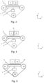
Fig. 3 is a schematic side view of the printing system inFig. 1 in a first step of the method according to the present invention; -
Fig. 4 is a schematic side view of the printing system inFig. 1 in a step of jetting a layer of marking material on the belt; -
Fig. 5 is a schematic side view of the printing system inFig. 1 in a first step of providing the layer of the marking material as an endless strip on the belt; and -
Fig. 6 is a schematic side view of the printing system inFig. 1 in a first step of printing on a print medium on the layer on the belt. - The present invention will now be described with reference to the accompanying drawings, wherein the same reference numerals have been used to identify the same or similar elements throughout the several views.
-
Fig. 1 shows a wideformat inkjet printer 1. The wide-format printer 1 comprises aninkjet printing assembly 7 for printing on aprint medium print medium Fig. 1 is a relatively rigid substrate, such as a panel. Theprint medium media input unit 14, which may be configured for storing a plurality ofsuch print media printer 1. Theprinter 1 comprises transport means for receiving and transporting theprint medium inkjet printing assembly 7. InFig. 1 , the transport means comprise anendless transport belt 4 supported on a plurality ofsupport rollers support rollers belt 4. Additionally, one or more one of thesupport rollers belt 4. Theinkjet printing assembly 7 may be provided with asensor 8, such as a CCD camera, to determine the relative position ofbelt 4 and/or theprint medium sensor 8 may be applied to control the position of thebelt 4 and/or theprint medium belt 4 is further provided with through-holes and asuction chamber 5 in connection with a suction source (not shown), such that an underpressure may be applied to theprint medium belt 4. The underpressure adheres theprint medium belt 4 and prevents displacement of theprint medium belt 4. Due to this holding thebelt 4 is able to transport theprint medium print medium - The
inkjet printing assembly 7 is configured to translate along afirst guide beam 6 in a scanning direction. The scanning direction is perpendicular to the direction in which the print medium is transported by thebelt 4. Theinkjet printing assembly 7 holds a plurality of print heads (not shown), which are configured to jet a plurality of different marking materials (different colors of ink, primers, coatings, etc.) on theprint medium printing assembly 7 is stored in one of a plurality of containers arranged in fluid connection with the respective print heads for supplying marking material to said print heads to print an image on theprint medium - The ejection of the marking material from the print heads is performed in accordance with data provided in the respective print job. The timing by which the droplets of marking material are released from the print heads determines their position on the
print medium inkjet printing assembly 7 along thefirst guide beam 6. The above mentionedsensor 8 may therein be applied to determine the relative position and/or velocity of theinkjet printing assembly 7 with respect to theprint medium sensor 8, the release timing of the marking material may be adjusted. - Upon ejection of the marking material, some marking material may be spilled and stay on a nozzle surface of the print heads. The marking material present on the nozzle surface, may negatively influence the ejection of droplets and the placement of these droplets on the
print medium - The marking materials may require treatment to properly fixate them on the print medium. Thereto, a
fixation unit 10 is provided downstream of theinkjet printing assembly 7. Thefixation unit 10 may emit heat and/or radiation to facilitate the marking material fixation process. In the example ofFig. 1 , thefixation unit 10 is a radiation emitter, which emits light of certain frequencies, which interacts with the marking materials, for example UV light in case of UV-curable inks. Thefixation unit 10 inFig. 1 is translatable along asecond guide beam 9.Other fixation units 10, such as page-wide curing or drying stations may also be applied. Further, theinkjet printing assembly 7 may be provided with a further fixation unit on the same carriage which holds the print heads. This further fixation unit can be used to (partially) cure and/or harden the marking materials, independent of or interaction with thefixation unit 10. - After printing, and optionally fixation, the
print medium print medium print medium media input unit 14. Optionally, the receiving unit may comprise processing means for processing themedium - The wide-
format printer 1 furthermore comprises auser interface 11 for receiving print jobs and optionally for manipulating print jobs. The localuser interface unit 11 is integrated to the print engine and may comprise a display unit and a control panel. Alternatively, the control panel may be integrated in the display unit, for example in the form of a touch-screen control panel. The localuser interface unit 11 is connected to acontroller 12 connected to theprinter 1. Thecontroller 12, for example a computer, comprises a processor adapted to issue commands to theprinter 1, for example for controlling the print process. Theprinter 1 may optionally be connected to a network. The connection to the network can be via cable or wireless. Theprinter 1 may receive printing jobs via the network. Further, optionally, thecontroller 12 of theprinter 1 may be provided with an input port, such as a USB port, so printing jobs may be sent to theprinter 1 via this input port. - The
printer 1 inFig. 1 is a so-called hybrid printer, capable of handling both flexible media and rigid substrates. InFig. 1 , theprinter 1 operates in a first print mode, wherein theprinter 1 is configured for transporting rigid substrates, such as theprint medium rigid print media rigid print media printer 1 inFig. 1 is configured with a substantially linear transport path: from themedia input device 14, theprint medium inkjet printing assembly 7 at a at substantially constant height. Themedia input unit 14 and the receiving unit are positioned at the level of the medium support surface of thebelt 4. InFig. 2 , aflexible web medium 16 is supplied to theprinter 1, whichweb medium 16 may be composed of e.g. paper, label stock, coated paper, plastic or textile. Theweb medium 16 is supplied from the input roller 2A and extends across thebelt 4 to the take-uproller 2B, where theweb medium 16 is re-wound. Theprinter 1 is configured to swiftly and efficiently switch between print modes. - The
print medium printing assembly 7. Thereto, theprint medium belt 4 by means of a negative pressure in thesuction chamber 5. This introduces a normal force Fn on theprint medium print medium belt 4. In consequence, a frictional force Ff in the horizontal directions X, Y is generated between thebelt 4 and theprint medium 
belt 4 and theprint medium belt 4, the coefficient of friction CF was found to reduce over time during prolonged operation of theprinter 1. This in turn reduces the frictional force Ff, increasing the chances of theprint medium 15, 16 (locally) slipping over thebelt 4. That results in positioning errors of theprint medium printing assembly 7, causing visible print artifacts in final print product. The frictional force Ff may be increased by increasing the negative pressure to increase the normal force Fn, but that results in more friction between thebelt 4 and thesuction chamber 5. This has the disadvantage that there is more wear on the inner surface of thebelt 4. Additionally stronger and/or more expensive drives may be required to move the belt to overcome the increased friction and/or to accurate position thebelt 4 under such increased friction.Figs. 3 to 6 provide an alternative method of increasing the frictional force Ff without requiring an increase in the normal force Fn. Instead, the method seeks to increase the coefficient of friction CF without requiring replacement of thebelt 4 itself. -
Fig. 3 show thebelt 4 in an initial, worn state. Thebelt 4 inFig. 3 has been used over a prolonged period in theprinter 1 and its surface has degraded, resulting in a lower coefficient of friction CF as compared to thebelt 4 when it was freshly installed in theprinter 1. First, it is determined that the coefficient of friction CF has decreased below a certain threshold, which may be expressed as a any suitable parameter, such as the commonly applied dimensionless values for coefficients of friction CF, a percentage, or a ratio, etc. The decrease in coefficient of friction CF may be determined by the operator or thecontroller 12 by executing a dedicated friction test job, wherein the displacement of the print medium is measured against the applied negative pressure. When it is found that the coefficient of friction CF has been decreased past the threshold, thecontroller 12 operates theprinter 1 in the belt maintenance mode. This may be triggered automatically by thecontroller 12 or scheduled by the operator. - In the belt maintenance mode, the
belt 4 is free of print media. Additionally, the suction device 5' is controlled, such that thesuction chamber 5 is at atmospheric pressure or a pressure that substantially prevents or reduces marking material from being sucked through thebelt 4 into thesuction chamber 5 and/or the suction device 5'. A slight overpressure may even be applied, though it should be sufficiently close to atmospheric pressure so that the trajectories of the jetted droplets are not affected. The suction device 5' may be turned off or its connection to thesuction chamber 5 may be temporarily sealed off. - Then, as shown in
Fig. 4 , thebelt 4 is driven into motion, such that the printing assembly is able to jet marking material directly onto thebelt 4. Thereby a layer of markingmaterial 4L is formed on the outer surface of thebelt 4. Thebelt 4 is moved stepwise to allow thescanning printing assembly 7 to print connecting swaths on thebelt 4. The swaths are preferably as wide as thebelt 4 measured in the scanning direction Y, as wide as theprinting assembly 7 will allow in case the printing assembly does not reach the lateral edges of thebelt 4. Since the suction device 5' is not actively connected to thesuction chamber 5, pollution of thesuction chamber 5 by marking material is avoided or minimized. Preferably, the swaths are provided with substantially constant coverage, so the thickness of thelayer 4L is homogenous. - The marking material applied in this example is a UV curable ink, as known in the state of the art, for example Canon Arizona UV IJC 255, 256, and/or 257 inks, as well Canon UVgel 460 inks, as commercially available in the year 2022 in any of the available colors.
- After printing, the deposited
layer 4L moves past thefixation unit 10. Thefixation unit 10 exposes thelayer 4L to a predetermined dose of UV light. The dose is sufficient to cure the UV curable marking material, thereby fixing it thebelt 4. Thefixation unit 10 may further be controlled to cure thelayer 4L, such that it is cured with a relatively high surface roughness, for example by quickly curing the jetted droplets before these have (fully) coalesced on the surface of thebelt 4. The surface roughness may further be controlled by the printing assembly depositing the droplets in predetermined patterns to create local height differences in thelayer 4L at the microscopic level. - The
layer 4L is preferably relatively thin and substantially follows the structure of thebelt 4. Thelayer 4L may be printed around any openings in thebelt 4. Openings in thelayer 4L over positioned over the openings in thebelt 4. Over the closed areas of thebelt 4, thelayer 4L is closed as well due to the coalescence of droplets there. Air can thus only flow perpendicular to thelayer 4L through thelayer 4L. - The deposition and fixation of marking material is continued until the
layer 4L forms a preferably endless strip on the surface of thebelt 4, as shownFig. 5 . Thelayer 4L becomes the new, outer surface of thebelt 4. Thelayer 4L is hardened and fixed to thebelt 4. The coefficient of friction of thelayer 4L is greater than that of thebelt 4 in the state shown inFig. 3 . Thelayer 4L is preferably continuous over the surface of thebelt 4 and interrupted only by the openings that were present in thebelt 4 prior to depositing thelayer 4L. - As the
layer 4L forms the new, outer surface, aprint medium belt 4 is in direct contact with thelayer 4L, as shown inFig. 6 . InFig. 6 , thecontroller 12 operates theprinter 1 in the printing mode for forming images onprint media suction chamber 5, so that a negative pressure is applied to theprint medium belt 4. - Although specific embodiments of the invention are illustrated and described herein, it will be appreciated by those of ordinary skill in the art that a variety of alternate and/or equivalent implementations exist. It should be appreciated that the exemplary embodiment or exemplary embodiments are examples only and are not intended to limit the scope, applicability, or configuration in any way. Rather, the foregoing summary and detailed description will provide those skilled in the art with a convenient road map for implementing at least one exemplary embodiment, it being understood that various changes may be made in the function and arrangement of elements described in an exemplary embodiment without departing from the scope as set forth in the appended claims and their legal equivalents. Generally, this application is intended to cover any adaptations or variations of the specific embodiments discussed herein.
- It will also be appreciated that in this document the terms "comprise", "comprising", "include", "including", "contain", "containing", "have", "having", and any variations thereof, are intended to be understood in an inclusive (i.e. non-exclusive) sense, such that the process, method, device, apparatus or system described herein is not limited to those features or parts or elements or steps recited but may include other elements, features, parts or steps not expressly listed or inherent to such process, method, article, or apparatus. Furthermore, the terms "a" and "an" used herein are intended to be understood as meaning one or more unless explicitly stated otherwise. Moreover, the terms "first", "second", "third", etc. are used merely as labels, and are not intended to impose numerical requirements on or to establish a certain ranking of importance of their objects.
- The present invention being thus described, it will be obvious that the same may be varied in many ways. Such variations are not to be regarded as a departure from the spirit and scope of the present invention, and all such modifications as would be obvious to one skilled in the art are intended to be included within the scope of the following claims.
Claims (15)
- A method of printing on an inkjet printer (1) comprising an endless transport belt (4) extending along a printing assembly (7), the method comprising the steps of :- depositing a layer (4L) of marking material on an outer surface of the belt (4) by means of the printing assembly (7) ;- fixing the layer (4L) to the belt (4) ;- transporting a print medium (15, 16) on the belt (4) with the layer (4L) on it, so that the print medium (15, 16) is transported along the printing assembly (7) for printing.
- The method according to any of the previous claims, wherein a coefficient of friction (CF) of the belt (4) with respect to a print medium (15, 16) after the step of depositing and fixing the layer (4L) is greater than before said steps.
- The method according to claim 2, wherein the coefficient of friction (CF) at a nominal surface roughness of the belt (4) with respect to a print medium (15, 16) after the step of depositing and fixing the layer (4L) is greater than the coefficient of friction (CF) at the same nominal surface roughness of the belt (4) with respect to the same print medium (15, 16) before said steps.
- The method according to claim 2 or 3, wherein the belt (4) is a mesh belt.
- The method according to any of the previous claims, wherein the layer (4L) has a substantially constant thickness.
- The method according to any of the previous claims, wherein the same printing assembly (7) is applied for depositing marking material on the belt (4) as for printing on the print medium (15, 16).
- The method according to claim 6, wherein the same marking material is applied for depositing marking material on the belt (4) as for printing on the print medium (15, 16).
- The method according to any of the previous claims, wherein the printer (1) further comprises a suction chamber (5) positioned on an opposite side of the belt (4) with respect to the printing assembly (7), and the method comprises the step of maintaining the suction chamber (5) at atmospheric pressure during the step of depositing the layer (4L) on the belt (4).
- The method according to any of the previous claims, wherein the marking material is a UV curable ink comprising a gellant and wherein the step of fixing comprises irradiating the deposited marking material with UV light.
- The method according to any of the previous claims, wherein the layer (4L) is formed as an endless strip with a width covering a majority of the belt (4) and/or a width corresponding to a printable area of the belt (4).
- An inkjet printer (1) comprising:- an endless, air permeable transport belt (4) extending along a printing assembly (7), along a fixation unit (10), and over a suction chamber (5) connectable to a suction device (5') for applying a negative pressure to the suction chamber (5);- a controller (12) configured to control the printer (1) in a belt maintenance mode, wherein the controller (12) is configured to:- drive the belt (4) at least one full rotation;- control the printing assembly (7) deposit a layer of marking material on the belt (4) during the at least one full rotation;- control the fixation unit (10) to fix the layer (4L) to the belt (4);
wherein the controller (12) is further configured to control the printer (1) in a printing mode, wherein the controller (12) is configured to:- drive the belt (4) with the deposited layer (4L) on it, such that a print medium (15, 16) on the belt (4) is transported along the printing assembly (7). - The printer (1) according to claim 11, wherein the controller (12) in the printing mode is further configured to:- control the printing assembly (7) deposit a layer of marking material on the print medium (15, 16); and- control the fixation unit (10) to fix the layer of marking material on the print medium (15, 16).
- The printer (1) according to claim 11 or 12, wherein in the belt maintenance mode the controller (12) is configured to prevent the suction device (5') from forming a negative pressure in the suction chamber (5) and in the printing mode is configured to control the suction device (5') to apply a negative pressure in the suction chamber (5).
- A computer program comprising instructions to cause the printer (1) according to any of the claims 11 to 13 execute the steps of the method of any of the claims 1 to 10.
- A computer-readable medium having stored thereon the computer program of claim 14.
Applications Claiming Priority (1)
| Application Number | Priority Date | Filing Date | Title |
|---|---|---|---|
| NL2033953A NL2033953B1 (en) | 2023-01-12 | 2023-01-12 | Printer with belt maintenance mode |
Publications (1)
| Publication Number | Publication Date |
|---|---|
| EP4400321A1 true EP4400321A1 (en) | 2024-07-17 |
Family
ID=89308682
Family Applications (1)
| Application Number | Title | Priority Date | Filing Date |
|---|---|---|---|
| EP23219106.4A Pending EP4400321A1 (en) | 2023-01-12 | 2023-12-21 | Inkjet printer with belt maintenance mode |
Country Status (2)
| Country | Link |
|---|---|
| EP (1) | EP4400321A1 (en) |
| NL (1) | NL2033953B1 (en) |
Citations (3)
| Publication number | Priority date | Publication date | Assignee | Title |
|---|---|---|---|---|
| JP2011073813A (en) * | 2009-09-29 | 2011-04-14 | Seiren Co Ltd | Inkjet recording apparatus and inkjet recording method |
| US20180264851A1 (en) * | 2015-09-02 | 2018-09-20 | Agfa Nv | Inkjet printing device with dimpled vacuum belt |
| US20180326757A1 (en) * | 2015-10-27 | 2018-11-15 | Agfa Nv | Inkjet printing method for heat sensitive substrates |
-
2023
- 2023-01-12 NL NL2033953A patent/NL2033953B1/en active
- 2023-12-21 EP EP23219106.4A patent/EP4400321A1/en active Pending
Patent Citations (3)
| Publication number | Priority date | Publication date | Assignee | Title |
|---|---|---|---|---|
| JP2011073813A (en) * | 2009-09-29 | 2011-04-14 | Seiren Co Ltd | Inkjet recording apparatus and inkjet recording method |
| US20180264851A1 (en) * | 2015-09-02 | 2018-09-20 | Agfa Nv | Inkjet printing device with dimpled vacuum belt |
| US20180326757A1 (en) * | 2015-10-27 | 2018-11-15 | Agfa Nv | Inkjet printing method for heat sensitive substrates |
Also Published As
| Publication number | Publication date |
|---|---|
| NL2033953B1 (en) | 2024-07-22 |
Similar Documents
| Publication | Publication Date | Title |
|---|---|---|
| JP4923296B2 (en) | Apparatus and method for printing on cardboard sheets | |
| US20100302331A1 (en) | Ink jet printing depth of focus control apparatus | |
| US12319051B2 (en) | Scanning inkjet printer with low friction transport belt | |
| EP4400321A1 (en) | Inkjet printer with belt maintenance mode | |
| AU2021251475B2 (en) | Apparatus for coating a surface with particles | |
| EP3359385A1 (en) | Tape coating apparatus and printing apparatus | |
| US12403702B2 (en) | Method and printer for printing and curing an image | |
| US20240176563A1 (en) | Method for queueing print jobs to be printed on rigid print media | |
| NL2032611B1 (en) | A printer with a definition roller for an endless belt | |
| EP4410557A1 (en) | Transport device for a scanning inkjet printer | |
| JP2019163117A (en) | Image formation apparatus and control method | |
| EP4420888A1 (en) | Method for operating a printing apparatus, printing apparatus and software product | |
| EP4410558A1 (en) | Method for operating a printing apparatus, printing apparatus and software product | |
| EP4410559A1 (en) | Method for operating a printing apparatus, printing apparatus and software product | |
| EP4600044A1 (en) | Sealing member for transporting porous print media in a hybrid printer | |
| EP4603289A1 (en) | A method for single handedly loading a wide format web in a printer | |
| EP4656396A1 (en) | A media edge curl preventer for a scanning inkjet printer comprising an endless suction transport belt | |
| EP4603290A1 (en) | A method for loading print media while tandem printing on a printer | |
| NL2032610B1 (en) | A transport device with quadrual drive for a scanning inkjet printer | |
| JP2026502741A (en) | Method for operating a printing device, printing device, and software product | |
| EP3470234A1 (en) | A method for preventing bleeding at the border of an image element | |
| JP2006231757A (en) | Inkjet recording device |
Legal Events
| Date | Code | Title | Description |
|---|---|---|---|
| PUAI | Public reference made under article 153(3) epc to a published international application that has entered the european phase |
Free format text: ORIGINAL CODE: 0009012 |
|
| STAA | Information on the status of an ep patent application or granted ep patent |
Free format text: STATUS: THE APPLICATION HAS BEEN PUBLISHED |
|
| AK | Designated contracting states |
Kind code of ref document: A1 Designated state(s): AL AT BE BG CH CY CZ DE DK EE ES FI FR GB GR HR HU IE IS IT LI LT LU LV MC ME MK MT NL NO PL PT RO RS SE SI SK SM TR |
|
| STAA | Information on the status of an ep patent application or granted ep patent |
Free format text: STATUS: REQUEST FOR EXAMINATION WAS MADE |
|
| 17P | Request for examination filed |
Effective date: 20250117 |
|
| GRAP | Despatch of communication of intention to grant a patent |
Free format text: ORIGINAL CODE: EPIDOSNIGR1 |
|
| STAA | Information on the status of an ep patent application or granted ep patent |
Free format text: STATUS: GRANT OF PATENT IS INTENDED |
|
| RIC1 | Information provided on ipc code assigned before grant |
Ipc: B41J 11/00 20060101AFI20260324BHEP Ipc: B29C 37/00 20060101ALI20260324BHEP |