EP4400152B1 - Systeme zur verwaltung von wundexsudat - Google Patents
Systeme zur verwaltung von wundexsudat Download PDFInfo
- Publication number
- EP4400152B1 EP4400152B1 EP24177965.1A EP24177965A EP4400152B1 EP 4400152 B1 EP4400152 B1 EP 4400152B1 EP 24177965 A EP24177965 A EP 24177965A EP 4400152 B1 EP4400152 B1 EP 4400152B1
- Authority
- EP
- European Patent Office
- Prior art keywords
- wound
- layer
- absorbent
- wound dressing
- pump
- Prior art date
- Legal status (The legal status is an assumption and is not a legal conclusion. Google has not performed a legal analysis and makes no representation as to the accuracy of the status listed.)
- Active
Links
Images


Classifications
-
- A—HUMAN NECESSITIES
- A61—MEDICAL OR VETERINARY SCIENCE; HYGIENE
- A61F—FILTERS IMPLANTABLE INTO BLOOD VESSELS; PROSTHESES; DEVICES PROVIDING PATENCY TO, OR PREVENTING COLLAPSING OF, TUBULAR STRUCTURES OF THE BODY, e.g. STENTS; ORTHOPAEDIC, NURSING OR CONTRACEPTIVE DEVICES; FOMENTATION; TREATMENT OR PROTECTION OF EYES OR EARS; BANDAGES, DRESSINGS OR ABSORBENT PADS; FIRST-AID KITS
- A61F13/00—Bandages or dressings; Absorbent pads
- A61F13/00051—Accessories for dressings
- A61F13/00055—Saturation indicators
-
- A—HUMAN NECESSITIES
- A61—MEDICAL OR VETERINARY SCIENCE; HYGIENE
- A61F—FILTERS IMPLANTABLE INTO BLOOD VESSELS; PROSTHESES; DEVICES PROVIDING PATENCY TO, OR PREVENTING COLLAPSING OF, TUBULAR STRUCTURES OF THE BODY, e.g. STENTS; ORTHOPAEDIC, NURSING OR CONTRACEPTIVE DEVICES; FOMENTATION; TREATMENT OR PROTECTION OF EYES OR EARS; BANDAGES, DRESSINGS OR ABSORBENT PADS; FIRST-AID KITS
- A61F13/00—Bandages or dressings; Absorbent pads
- A61F13/02—Adhesive bandages or dressings
- A61F13/0203—Adhesive bandages or dressings with fluid retention members
- A61F13/0206—Adhesive bandages or dressings with fluid retention members with absorbent fibrous layers, e.g. woven or non-woven absorbent pads or island dressings
-
- A—HUMAN NECESSITIES
- A61—MEDICAL OR VETERINARY SCIENCE; HYGIENE
- A61F—FILTERS IMPLANTABLE INTO BLOOD VESSELS; PROSTHESES; DEVICES PROVIDING PATENCY TO, OR PREVENTING COLLAPSING OF, TUBULAR STRUCTURES OF THE BODY, e.g. STENTS; ORTHOPAEDIC, NURSING OR CONTRACEPTIVE DEVICES; FOMENTATION; TREATMENT OR PROTECTION OF EYES OR EARS; BANDAGES, DRESSINGS OR ABSORBENT PADS; FIRST-AID KITS
- A61F13/00—Bandages or dressings; Absorbent pads
- A61F13/05—Bandages or dressings; Absorbent pads specially adapted for use with sub-pressure or over-pressure therapy, wound drainage or wound irrigation, e.g. for use with negative-pressure wound therapy [NPWT]
-
- A—HUMAN NECESSITIES
- A61—MEDICAL OR VETERINARY SCIENCE; HYGIENE
- A61M—DEVICES FOR INTRODUCING MEDIA INTO, OR ONTO, THE BODY; DEVICES FOR TRANSDUCING BODY MEDIA OR FOR TAKING MEDIA FROM THE BODY; DEVICES FOR PRODUCING OR ENDING SLEEP OR STUPOR
- A61M1/00—Suction or pumping devices for medical purposes; Devices for carrying-off, for treatment of, or for carrying-over, body-liquids; Drainage systems
- A61M1/71—Suction drainage systems
- A61M1/78—Means for preventing overflow or contamination of the pumping systems
- A61M1/784—Means for preventing overflow or contamination of the pumping systems by filtering, sterilising or disinfecting the exhaust air, e.g. swellable filter valves
-
- A—HUMAN NECESSITIES
- A61—MEDICAL OR VETERINARY SCIENCE; HYGIENE
- A61M—DEVICES FOR INTRODUCING MEDIA INTO, OR ONTO, THE BODY; DEVICES FOR TRANSDUCING BODY MEDIA OR FOR TAKING MEDIA FROM THE BODY; DEVICES FOR PRODUCING OR ENDING SLEEP OR STUPOR
- A61M1/00—Suction or pumping devices for medical purposes; Devices for carrying-off, for treatment of, or for carrying-over, body-liquids; Drainage systems
- A61M1/71—Suction drainage systems
- A61M1/79—Filters for solid matter
-
- A—HUMAN NECESSITIES
- A61—MEDICAL OR VETERINARY SCIENCE; HYGIENE
- A61M—DEVICES FOR INTRODUCING MEDIA INTO, OR ONTO, THE BODY; DEVICES FOR TRANSDUCING BODY MEDIA OR FOR TAKING MEDIA FROM THE BODY; DEVICES FOR PRODUCING OR ENDING SLEEP OR STUPOR
- A61M1/00—Suction or pumping devices for medical purposes; Devices for carrying-off, for treatment of, or for carrying-over, body-liquids; Drainage systems
- A61M1/84—Drainage tubes; Aspiration tips
- A61M1/86—Connectors between drainage tube and handpiece, e.g. drainage tubes detachable from handpiece
-
- A—HUMAN NECESSITIES
- A61—MEDICAL OR VETERINARY SCIENCE; HYGIENE
- A61M—DEVICES FOR INTRODUCING MEDIA INTO, OR ONTO, THE BODY; DEVICES FOR TRANSDUCING BODY MEDIA OR FOR TAKING MEDIA FROM THE BODY; DEVICES FOR PRODUCING OR ENDING SLEEP OR STUPOR
- A61M1/00—Suction or pumping devices for medical purposes; Devices for carrying-off, for treatment of, or for carrying-over, body-liquids; Drainage systems
- A61M1/90—Negative pressure wound therapy devices, i.e. devices for applying suction to a wound to promote healing, e.g. including a vacuum dressing
- A61M1/91—Suction aspects of the dressing
- A61M1/912—Connectors between dressing and drainage tube
-
- A—HUMAN NECESSITIES
- A61—MEDICAL OR VETERINARY SCIENCE; HYGIENE
- A61M—DEVICES FOR INTRODUCING MEDIA INTO, OR ONTO, THE BODY; DEVICES FOR TRANSDUCING BODY MEDIA OR FOR TAKING MEDIA FROM THE BODY; DEVICES FOR PRODUCING OR ENDING SLEEP OR STUPOR
- A61M1/00—Suction or pumping devices for medical purposes; Devices for carrying-off, for treatment of, or for carrying-over, body-liquids; Drainage systems
- A61M1/90—Negative pressure wound therapy devices, i.e. devices for applying suction to a wound to promote healing, e.g. including a vacuum dressing
- A61M1/91—Suction aspects of the dressing
- A61M1/915—Constructional details of the pressure distribution manifold
-
- A—HUMAN NECESSITIES
- A61—MEDICAL OR VETERINARY SCIENCE; HYGIENE
- A61M—DEVICES FOR INTRODUCING MEDIA INTO, OR ONTO, THE BODY; DEVICES FOR TRANSDUCING BODY MEDIA OR FOR TAKING MEDIA FROM THE BODY; DEVICES FOR PRODUCING OR ENDING SLEEP OR STUPOR
- A61M39/00—Tubes, tube connectors, tube couplings, valves, access sites or the like, specially adapted for medical use
- A61M39/22—Valves or arrangement of valves
- A61M39/24—Check- or non-return valves
-
- B—PERFORMING OPERATIONS; TRANSPORTING
- B01—PHYSICAL OR CHEMICAL PROCESSES OR APPARATUS IN GENERAL
- B01D—SEPARATION
- B01D35/00—Filtering devices having features not specifically covered by groups B01D24/00 - B01D33/00, or for applications not specifically covered by groups B01D24/00 - B01D33/00; Auxiliary devices for filtration; Filter housing constructions
- B01D35/02—Filters adapted for location in special places, e.g. pipe-lines, pumps, stop-cocks
-
- A—HUMAN NECESSITIES
- A61—MEDICAL OR VETERINARY SCIENCE; HYGIENE
- A61M—DEVICES FOR INTRODUCING MEDIA INTO, OR ONTO, THE BODY; DEVICES FOR TRANSDUCING BODY MEDIA OR FOR TAKING MEDIA FROM THE BODY; DEVICES FOR PRODUCING OR ENDING SLEEP OR STUPOR
- A61M1/00—Suction or pumping devices for medical purposes; Devices for carrying-off, for treatment of, or for carrying-over, body-liquids; Drainage systems
- A61M1/90—Negative pressure wound therapy devices, i.e. devices for applying suction to a wound to promote healing, e.g. including a vacuum dressing
- A61M1/92—Negative pressure wound therapy devices, i.e. devices for applying suction to a wound to promote healing, e.g. including a vacuum dressing with liquid supply means
-
- A—HUMAN NECESSITIES
- A61—MEDICAL OR VETERINARY SCIENCE; HYGIENE
- A61M—DEVICES FOR INTRODUCING MEDIA INTO, OR ONTO, THE BODY; DEVICES FOR TRANSDUCING BODY MEDIA OR FOR TAKING MEDIA FROM THE BODY; DEVICES FOR PRODUCING OR ENDING SLEEP OR STUPOR
- A61M1/00—Suction or pumping devices for medical purposes; Devices for carrying-off, for treatment of, or for carrying-over, body-liquids; Drainage systems
- A61M1/90—Negative pressure wound therapy devices, i.e. devices for applying suction to a wound to promote healing, e.g. including a vacuum dressing
- A61M1/98—Containers specifically adapted for negative pressure wound therapy
- A61M1/984—Containers specifically adapted for negative pressure wound therapy portable on the body
- A61M1/985—Containers specifically adapted for negative pressure wound therapy portable on the body the dressing itself forming the collection container
-
- A—HUMAN NECESSITIES
- A61—MEDICAL OR VETERINARY SCIENCE; HYGIENE
- A61M—DEVICES FOR INTRODUCING MEDIA INTO, OR ONTO, THE BODY; DEVICES FOR TRANSDUCING BODY MEDIA OR FOR TAKING MEDIA FROM THE BODY; DEVICES FOR PRODUCING OR ENDING SLEEP OR STUPOR
- A61M2205/00—General characteristics of the apparatus
- A61M2205/75—General characteristics of the apparatus with filters
- A61M2205/7527—General characteristics of the apparatus with filters liquophilic, hydrophilic
-
- A—HUMAN NECESSITIES
- A61—MEDICAL OR VETERINARY SCIENCE; HYGIENE
- A61M—DEVICES FOR INTRODUCING MEDIA INTO, OR ONTO, THE BODY; DEVICES FOR TRANSDUCING BODY MEDIA OR FOR TAKING MEDIA FROM THE BODY; DEVICES FOR PRODUCING OR ENDING SLEEP OR STUPOR
- A61M39/00—Tubes, tube connectors, tube couplings, valves, access sites or the like, specially adapted for medical use
- A61M39/10—Tube connectors; Tube couplings
-
- B—PERFORMING OPERATIONS; TRANSPORTING
- B01—PHYSICAL OR CHEMICAL PROCESSES OR APPARATUS IN GENERAL
- B01D—SEPARATION
- B01D29/00—Filters with filtering elements stationary during filtration, e.g. pressure or suction filters, not covered by groups B01D24/00 - B01D27/00; Filtering elements therefor
- B01D29/11—Filters with filtering elements stationary during filtration, e.g. pressure or suction filters, not covered by groups B01D24/00 - B01D27/00; Filtering elements therefor with bag, cage, hose, tube, sleeve or like filtering elements
- B01D29/114—Filters with filtering elements stationary during filtration, e.g. pressure or suction filters, not covered by groups B01D24/00 - B01D27/00; Filtering elements therefor with bag, cage, hose, tube, sleeve or like filtering elements arranged for inward flow filtration
Definitions
- the present disclosure generally relates to wound exudate management systems, and more particularly but not exclusively relates to inline filters for such wound exudate management systems.
- Wound healing is composed of four phases: hemostasis, inflammation, proliferation, and maturation. Managing exudate during the hemostasis and proliferation phases of wound healing is vital to prevent maceration, recurring infection, and other adverse effects on the patients.
- Wound dressings that exert negative pressure at the site of wound absorb excess excaudate and promote healing. Exerting and maintaining negative pressure of wound dressings is ideal for treating and managing various types of chronic or acute dermal wounds stemmed from infection, ulcers, burns, abrasions, incisions, lacerations, punctures, avulsions, and amputations.
- Wound exudate management systems comprising a negative pressure generating system (such as a pump or a vacuum source) can be used in conjunction with wound dressings to achieve negative pressure at the site of a wound without the need of a canister.
- a negative pressure generating system such as a pump or a vacuum source
- exudate from the wound can exceed the absorbing capacity of the wound dressing and subsequently enter the wound exudate management system, which may damage the components of the system, including the pump unit.
- excess exudate can create blockage in the wound exudate management system, disrupting the maintenance of the negative pressure.
- US 2019/0125945 A1 relates to a system for diluting therapeutic gas effluent flowing from a dressing, and including a filter that may comprise a hydrophobic material.
- a wound exudate management system comprising an inline filter according to claim 1.
- Optional features of the invention are set out in the dependent claims.
- the at least one filter membrane is positioned between the one-way check valve and the outlet opening. In still other embodiments, the at least one filter membrane is positioned between the inlet opening and the one-way check valve.
- the filter membrane comprises hydrophobic material.
- the hydrophobic material comprises polyether ether ketone (PEEK), hydrophobic polycarbonate (PCTE), polyester (PETE), polypropylene, hydrophobic polytetrafluoroethylene (PTFE), hydrophobic polyvinylidene difluoride (PVDF), or hydrophobic glass fiber.
- the absorbent material is disposed within the interior cavity of the envelope structure.
- the absorbent material comprises carboxymethylated cellulose fibers.
- the wound contact layer comprises carboxymethylated cellulose fibers.
- the wound contact layer comprises reinforcing nylon stitching.
- the pressure dispersion layer comprises reticulated foam.
- the wound exudate management systems disclosed herein further comprises fenestrations in the one or more of the plurality of layers of absorbent material. In certain embodiments, the wound exudate management systems further comprise a pressure conveyance disposed within the flexible connector. In some embodiments, the wound exudate management systems disclosed herein further comprise a status indicator, the status indicator providing visual cues indicating when the pump is off, on, or on but malfunctioning.
- the pump maintains a negative pressure of 80 mmHg in the wound dressing. In some embodiments, the pump maintains a negative pressure between 100 mmHg and 150 mmHg. In some embodiments, the pump maintains a negative pressure of 125 mmHg in the wound dressing. In some instances, the wound exudate is absorbed and prevented from entering the pump by the at least one filter membrane of the inline filter. In some instances, the pump comprises a status indicator providing visual cues indicating when the pump is off, on, or on but malfunctioning. In some embodiments, the malfunctioning of the pump is triggered by a negative pressure outside of the negative pressure range between 40 mmHg to 200 mmHg in the wound dressing, or between 100 mmHg to 150 mmHg in the wound dressing.
- references in the specification to "one embodiment,” “an embodiment,” “an illustrative embodiment,” etc., indicate that the embodiment described may include a particular feature, structure, or characteristic, but every embodiment may or may not necessarily include that particular feature, structure, or characteristic. Moreover, such phrases are not necessarily referring to the same embodiment. It should further be appreciated that although reference to a "preferred" component or feature may indicate the desirability of a particular component or feature with respect to an embodiment, the disclosure is not so limiting with respect to other embodiments, which may omit such a component or feature. Further, when a particular feature, structure, or characteristic is described in connection with an embodiment, it is submitted that it is within the knowledge of one skilled in the art to implement such feature, structure, or characteristic in connection with other embodiments whether or not explicitly described.
- items included in a list in the form of "at least one of A, B, and C” can mean (A); (B); (C); (A and B); (B and C); (A and C); or (A, B, and C).
- items listed in the form of "at least one of A, B, or C” can mean (A); (B); (C); (A and B); (B and C); (A and C); or (A, B, and C).
- Items listed in the form of "A, B, and/or C” can also mean (A); (B); (C); (A and B); (B and C); (A and C); or (A, B, and C).
- the wound exudate management system comprises a wound dressing and a portable pump.
- the wound exudate management system creates and maintains a negative pressure at the site of the wound as part of the NPWT.
- a wound dressing is applied to a site of a wound as part of a wound exudate management system comprising a portable pump, and a negative pressure is exerted and maintained on the wound by the portable pump. Adequate levels of negative pressure in the wound dressing can be continuously monitored by the pump, and the inline filter prevents excess exudate from entering the pump and or its associated tubing.
- compositions comprising inline filters for use with a wound exudate management system and methods of using the inline filter as part of the wound exudate management system to treat various types of wounds.
- the inline filter disclosed herein comprises an inlet opening having a fitting or tube connector, an outlet opening having a fitting or tube connector, and a cartridge flanked by the inlet and outlet openings.
- the cartridge comprises a cavity, a one-way check valve, and at least one filter membrane.
- the one-way check valve and the at least one filter membrane are housed inside the cavity of the cartridge and perpendicular to the inlet opening and the outlet opening.
- the at least one filter membrane is positioned between the inlet opening and the one-way check valve.
- the at least one filter membrane is positioned between the one-way check valve and the outlet opening.
- a first filter membrane is positioned between the inlet opening and the one-way check valve, and a second filter membrane is positioned between the one-way check valve and the outlet opening.
- inline filters comprising filter membranes comprising hydrophobic material.
- the inline filters disclosed herein comprise a pore size of at least 0.2 microns, In some embodiments, the inline filters disclosed herein comprise a pore size of at least 0.3 microns, 0.4 microns, 0.5 microns, 0.6 microns, 0.7 microns, 0.8 microns, 0.9 microns, 1.0 microns, 1.1 microns, 1.2 microns, 1.3 microns, 1.4 microns, 1.5 microns, 1.6 microns, 1.7 microns, 1.8 microns, 1.9 microns, 2.0 microns, 2.1 microns, 2.2 microns, 2.3 microns, 2.4 microns, 2.5 microns, 2.6 microns, 2.7 microns, 2.8 microns, 2.9 microns, 3.0 microns, 3.1 microns, 3.2 microns, 3.3 microns, 3.4 microns, 3.5 microns, 3.6 microns, 3.7 microns, 3.8 micron
- the wound exudate is absorbed or prevented from entering the pump by the inline filter.
- the status of the maintenance of negative pressure is monitored by a status indicator.
- FIG. 1A shows an image of an exemplary inline filter 100 next to a luer fitting without an inline filter 90.
- FIG. 1B shows a cutaway view of a design of an exemplary inline filter 200 as disclosed herein. Fluid flows from left to right in the orientation shown in FIG. 1B .
- the inline filter 200 includes an inlet opening 210 having a first connector 212, an outlet opening 220 having a second connector 222, and a cartridge 230 flanked by the inlet opening 210 and the outlet opening 202.
- the cartridge 230 comprises a cavity 232, a one-way check valve 234, and at least one filter membrane 236.
- the one-way check valve 234 and the at least one filter membrane 236 are housed inside the cavity 232 and perpendicular to the inlet opening 210 and the outlet opening 220.
- the at least one filter membrane 236 is positioned between the one-way check valve 234 and the outlet opening 220. Additionally or alternatively, the at least one filter membrane 236 may be positioned between the inlet opening 210 and the one-way check valve 234.
- the filter membrane 236 comprises a pore size of at least 0.2 microns.
- the at least one filter membrane 236 comprises hydrophobic material.
- the hydrophobic material may, for example, comprise polyether ether ketone (PEEK), hydrophobic polycarbonate (PCTE), polyester (PETE), polypropylene, hydrophobic polytetrafluoroethylene (PTFE), hydrophobic polyvinylidene difluoride (PVDF), or hydrophobic glass fiber.
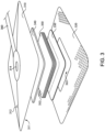
- FIGS. 2 and 3 illustrated therein is a schematic of an exemplary wound dressing 300 for use in combination with the inline filters disclosed here.
- the illustrated wound dressing 300 generally includes a backing layer 310 and an adhesive layer 320 for adhering the wound dressing 300 adjacent the wound.
- the wound dressing 300 further comprises a wound contact layer 330 for contacting the wound, a pressure dispersion layer 340, a plurality of absorbent material layers 350 disposed between the wound contact layer 330 and the pressure dispersion layer 340.
- the backing layer 310 has a first surface 311 and a second surface 312, and the first surface 351 is adjacent, and in contact with, the pressure dispersion layer 340 and the adhesive layer 320.
- the backing layer 310 is formed of a polyurethane film.
- the backing layer 310 comprises a port 314 through which exudate may flow to a tube 360.
- the adhesive layer 320 generally defines a border about an opening 322 for receiving the wound.
- the adhesive layer 320 comprises a silicone adhesive.
- the adhesive layer 320 may be perforated.
- the wound contact layer 330 overlaps the border defined by the adhesive layer 320, and is configured to contact the wound via the opening 322.
- the wound contact layer 330 may comprise Medicel TM .
- the wound contact layer 330 comprises carboxymethylated cellulose fibers.
- the wound contact layer 330 may comprise HYDROFIBER ® .
- the wound contact layer 330 may be reinforced, for example via nylon stitching. Thus, the wound contact layer 330 may comprise reinforcing nylon stitching 332.
- the pressure dispersion layer 340 is adjacent and in contact with the first surface 311 of the backing 310.
- the pressure dispersion layer 340 may be provided as a polyester foam layer.
- the pressure dispersion layer 340 comprises reticulated foam.
- the absorbent material layers 350 are positioned between the wound contact layer 330 and the pressure dispersion layer 340.
- the wound dressing 300 may, for example, comprise eight absorbent material layers 350.
- one or more of the absorbent material layers 350 may comprise carboxymethylated cellulose fibers.
- one or more of the absorbent material layers 350 may comprise Medicel TM .
- one or more of the absorbent material layers 350 may comprise HYDROFIBER ® .
- one or more of the absorbent material layers 350 further comprises fenestrations 352.
- the tube 360 is connected with the port 314 in the backing layer 310.
- An adhesive ring 366 may form a seal between one end 361 of the tube 360 and the port 314.
- the opposite end 362 of the tube 360 may be connected with a fitting such as a Luer lock 364.
- a disc 368 such as one comprising Medicel TM , may be positioned in the port 314.
- the wound dressing 300 may include an additional layer 370 between the pressure dispersion layer 340 and the uppermost absorbent layer 350.
- the additional layer 370 may, for example, be formed of thermoplastic.
- the additional layer 370 may be provided as a thermoplastic spun lace layer.
- the wound dressing 300 may further comprise a nonwoven spun lace layer 372 connected to the wound contact layer 330.
- an envelope structure 374 is formed by joining peripheral portions 373 of the thermoplastic spun lace layer 370 and the nonwoven spun lace layer 372 such that the plurality of absorbent material layers 350 are disposed substantially within an interior cavity 375 of the envelope structure 374, for example as illustrated in Fig. 4 .
- the absorbent material layers 350 are disposed within the interior cavity 375 of the envelope structure 374.
- the wound dressing 300 may include a further layer 380 positioned between the wound contact layer 330 and the lowermost absorbent layer 350.
- the further layer 380 may, for example, be a polyester/viscose layer.
- the wound exudate management system 400 comprises a pump 410 for generating negative pressure, a wound dressing 420 for covering and protecting a wound, an inline filter 430, a first pressure tube 440 having a first interior lumen 442, a second pressure tube 450 having a second interior lumen 452, and a flexible connector 460.
- the first pressure tube 440 is disposed between the pump 410 and the inline filter 430.
- the second pressure tube 450 is disposed between the inline filter 430 and the flexible connector 460.
- the flexible connector 460 is disposed between the second pressure tube 450 and the wound dressing 420 such that the pump 410 and the wound dressing 420 are in fluid communication via the interior lumens 442, 452.
- the wound dressing 420 may be provided along the lines of the above-described wound dressing 300.
- the inline filter 430 may be provided along the lines of the above-described inline filter 200.
- a pressure conveyance 462 is disposed within the flexible connector 460.
- certain embodiments further comprise an absorbent indicator 470, such as the disc 368, and an adhesive member 480 such as the adhesive ring 366.
- the adhesive member 480 may adhere the flexible connector 460 and the absorbent indicator 480 to the wound dressing 420.
- the absorbent indicator is positioned in a flow pathway at a location between the absorbent layers 350 and the flexible 460.
- the absorbent indicator 470 is capable of absorbing exudate to indicate the presence of exudate at the side of the absorbent layer 350 furthest from the wound.
- the absorbent indicator 470 gives a visual indication of the presence of exudate at the side of the absorbent layer 350 furthest from the wound.
- Certain embodiments of the system 400 further comprise a status indicator 490 configured to provide visual cues indicating when the pump is off, on, and/or on but malfunctioning.
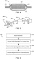
- FIG. 6 an exemplary process 500 that may be performed using the system 400 is illustrated.
- Blocks illustrated for the processes in the present application are understood to be examples only, and blocks may be combined or divided, and added or removed, as well as re-ordered in whole or in part, unless explicitly stated to the contrary. Additionally, while the blocks are illustrated in a relatively serial fashion, it is to be understood that two or more of the blocks may be performed concurrently or in parallel with one another.
- process 500 is described herein with specific reference to an implementation of the system 400 in which the inline filter 430 is provided as the inline filter 200 and the dressing 420 is provided in the form of the dressing 300, it is to be appreciated that the process 500 may be performed with inline filters, dressings 300and/or systems having additional or alternative features.
- the process 500 may begin with block 510, which generally involves obtaining an inline filter such as the inline filter 200.
- the inline filter obtained in block 510 generally comprises an inlet opening 210, an outlet opening 220, and a cartridge 230 flanked by the inlet opening 210 and the outlet openings 220.
- the cartridge 230 comprises a 232 housing a one-way check valve 234 and at least one filter membrane 236.
- the process 500 may include block 520, which generally involve connecting the outlet opening to a first pressure tube.
- block 520 may involve connecting the outlet opening 220 to the first pressure tube 440, wherein the first pressure tube 440 is connected to a pump 410 on the opposite end of the first pressure tube 440 that is connected to the outlet opening 220.
- the process 500 may include block 530, which generally involves connecting the inlet opening to a second pressure tube.
- block 530 may involve connecting the inlet opening 210 to a second pressure tube 450, wherein the second pressure tube 450 is connected to the wound dressing 300 on the opposite end of the second pressure tube 450 that is connected to the inlet opening 210.
- the process 500 may further include block 540, which generally involves generating negative pressure in the wound dressing by actuating the pump to draw air away from the wound dressing.
- block 540 may involve generating negative pressure in the wound dressing 300/420 by actuating the pump 410 to draw air away from the wound dressing 300/420.
- the pump 410 maintains a negative pressure between 40 mmHg and 125 mmHg in the wound dressing 300/420.
- the pump 410 maintains a negative pressure of 80 mmHg in the wound dressing 300/420.
- the pump maintains a negative pressure of 125 mmHg in the wound dressing 300/420.
- the wound exudate is absorbed and prevented from entering the pump 410 by the at least one filter membrane 236 of the inline filter 200/430.
- the pump 410 comprises a status indicator 490 providing visual cues indicating when the pump 410 is off, on, and/or on but malfunctioning.
- the malfunctioning of the pump 410 is triggered by a negative pressure outside of the negative pressure range between 40 mmHg to 125 mmHg in the wound dressing 300/420.
- the malfunctioning of the pump 410 is triggered by a negative pressure outside of the negative pressure range between 100 mmHg to 150 mmHg in the wound dressing 300/420.
- an inline filter 200 comprising an inlet opening 210 having a fitting or tube connector 212, an outlet opening 220 having a fitting or tube connector 222, and a cartridge 230 flanked by the inlet opening 210 and the outlet opening 220.
- fitting or tube connector 212, 222 for the inlet and outlet openings 210, 220 include compression fittings, quick disconnect fittings, cam fittings, bite-type fittings, mechanical grip fittings, flare fittings, flange fittings, luer locks, push-to-connect connector, quick coupler, threaded fittings, nipple, barb, and valve.
- the fitting or tube connector of the inlet and outlet openings further comprise an adapter, coupling, sleeve, union, cap, plug, reducer, olet, or a combination thereof.
- the inlet and outlet openings comprise luer locks to be connected with pressure tubes, where the pressure tubes comprise complementary ends of the luer locks to the inlet and outlet openings.
- the fitting or tube connector of the inlet and outlet openings comprise fitting with added or changed directions such as elbow adapter, 'T' adapter, 'Y' adapter, or cross adapter.
- the cartridge 230 flanked by the inlet and outlet openings 210, 220 comprises a cavity 232 and a one-way check valve 234.
- the one-way check valve 234 is housed inside the cavity 232 of the cartridge 230 and perpendicular to the inlet and outlet openings 210, 220.
- a non-limiting exemplary list of the one-way check valve 234 housed inside the cavity 232 includes diaphragm check valve, swing check valve, tilting disc check valve, plug type check valve, ball type check valve, dual disc check valve, clapper valve, stop check valve, life-check valve, in-line check valve, duckbill valve, and pneumatic non-return valve.
- the cartridge 230 flanked by the inlet and outlet openings 210, 220 comprises a cavity 232, a one-way check valve 234, and at least one filter membrane 236.
- the one-way check valve 234 and the at least one filter membrane 236 are housed inside the cavity 232 of the cartridge 230 and perpendicular to the inlet and outlet openings 210, 220.
- the at least one filter membrane 236 is positioned between the inlet opening 210 and the one-way check valve 234.
- the at least one filter membrane 236 is positioned between the one-way check valve 234 and the outlet opening 220.
- a first filter membrane 236A is positioned between the inlet opening 210 and the one-way check valve 234, and a second filter membrane 236B is positioned between the one-way check valve 234 and the outlet opening 220.
- the filter membrane 236 of the inline filter 200 disclosed herein comprises a diameter of less than 50 mm, less than 45 mm, less than 40 mm, less than 35 mm, less than 30 mm, less than 25 mm, less than 24 mm, less than 23 mm, less than 22 mm, less than 21 mm, less than 20 mm, less than 19 mm, less than 18 mm, less than 17 mm, less than 16 mm, less than 15 mm, less than 14 mm, less than 13 mm, less than 12 mm, less than 11 mm, less than 10 mm, less than 9 mm, less than 8 mm, less than 7 mm, less than 6 mm, or less than 5 mm.
- the filter membrane 236 of the inline filter 200 comprises a thickness of less than 50 mm, less than 45 mm, less than 40 mm, less than 35 mm, less than 30 mm, less than 25 mm, less than 24 mm, less than 23 mm, less than 22 mm, less than 21 mm, less than 20 mm, less than 19 mm, less than 18 mm, less than 17 mm, less than 16 mm, less than 15 mm, less than 14 mm, less than 13 mm, less than 12 mm, less than 11 mm, less than 10 mm, less than 9 mm, less than 8 mm, less than 7 mm, less than 6 mm, or less than 5 mm, or less than 4 mm, or less than 3 mm, or less than 2 mm, or less than 1 mm, or less than 0.5 mm, or less than 0.4 mm, or less than 0.3 mm, or less than 0.2 mm, or less than 0.1 mm, or less than 0.05 mm.
- the filter membrane 236 of the inline filter 200 comprises a pore size of at least 0.2 microns.
- the filter membrane 236 of the inline filter 200 comprises a pore size of at least 0.3 microns, 0.4 microns, 0.5 microns, 0.6 microns, 0.7 microns, 0.8 microns, 0.9 microns, 1.0 microns, 1.1 microns, 1.2 microns, 1.3 microns, 1.4 microns, 1.5 microns, 1.6 microns, 1.7 microns, 1.8 microns, 1.9 microns, 2.0 microns, 2.1 microns, 2.2 microns, 2.3 microns, 2.4 microns, 2.5 microns, 2.6 microns, 2.7 microns, 2.8 microns, 2.9 microns, 3.0 microns, 3.1 microns, 3.2 microns, 3.3 microns, 3.4 microns, 3.5 microns, 3.6 microns, 3.7 microns
- the filter membrane 236 comprises hydrophobic material.
- hydrophobic material for the filter membrane include polyether ether ketone (PEEK), hydrophobic polycarbonate (PCTE), polyester (PETE), polypropylene, hydrophobic polytetrafluoroethylene (PTFE), hydrophobic polyvinylidene difluoride (PVDF), or hydrophobic glass fiber.
- PEEK polyether ether ketone
- PCTE hydrophobic polycarbonate
- PET polyester
- polypropylene polypropylene
- PTFE hydrophobic polytetrafluoroethylene
- PVDF hydrophobic polyvinylidene difluoride
- glass fiber hydrophobic glass fiber.
- the first filter membrane and the second filter membrane comprise of the same material.
- the first filter membrane and the second filter membrane comprise of different material.
- the inline filters disclosed herein comply with standards which specify usability requirements for the development of and use of medical devices, such as IEC 62366-1.
- the inline filters disclosed herein are biocompatible for their intended use and meet requirements for animal derived components.
- the inline filters disclosed herein are configured for one-time use. In some embodiments, the inline filters disclosed herein are configured for use by not more than one patient.
- the inline filters disclosed herein are capable of sterilization. In some embodiments, the inline filters are sterilized by electron beam (E-beam), gamma sterilization or ethylene oxide sterilization. In some embodiments, the inline filters still perform to the desired specification following sterilization. In some embodiments, the inline filters disclosed herein do not comprise latex. In some embodiments, the inline filters disclosed herein do not comprise Bis(2-ethylhexyl) phthalate (DEHP).
- E-beam electron beam
- gamma sterilization ethylene oxide sterilization
- the inline filters still perform to the desired specification following sterilization.
- the inline filters disclosed herein do not comprise latex. In some embodiments, the inline filters disclosed herein do not comprise Bis(2-ethylhexyl) phthalate (DEHP).
- the inline filters disclosed herein comprise an outlet opening 220 with a fitting or a connector 212 that is configured to form an airtight fitting with a first pressure tube 450 connecting the inline filter 200 to a pump portion 410 of a wound exudate management system 400.
- the inline filters disclosed herein comprise an inlet opening 210 having a fitting or a connecter 212 for forming an airtight connection with a second pressure tube 450 connected to the flexible connector 460, which is connected to a wound dressing 300/420.
- the pump 410, first pressure tube 440, inline filter 430, second pressure tube 450, and flexible connector 460 create a continuous lumen 401 in a wound exudate management system 460. Actuation of the pump 410 draws air away from the wound dressing 420, creating a negative pressure in the wound dressing 420 and the continuous lumen 401.
- the inline filters disclosed herein prevent exudate from accidentally entering a first pressure tube connected to a pump, and prevent the pump from malfunctioning.
- the inline filter 200/430 may prevent exudate from accidentally entering the first pressure tube 440 to thereby prevent the pump 410 from malfunctioning as a result of such exudate.
- Exudate which comes in contact with the disclosed inline filters 430 may also cause a drop in the negative pressure of the entire wound exudate management system 400 during use.
- a status indicator 490 on the pump 410 can alert a user regarding potential malfunctioning of the wound exudate system 400, which may result in the user replacing the wound dressing 420 and/or blocked inline filter 430 with a new inline filter 430 in order to restore the negative pressure in the wound dressing 420.
- the inline filters disclosed herein are included with a negative pressure wound dressing system such as the negative pressure wound dressing system 400.
- the inline filters disclosed herein comprise inline filter packaging systems. Suitable materials for inline filter packaging systems are easily torn and include, by way of non-limiting examples, paper and waxed paper.
- the inline filter packaging system protects the product from physical damage during transit and storage.
- the inline filter packaging system is openable by hand.
- the inline filter packaging system clearly identifies an opening end.
- the inline filter packaging system states shipping and storage conditions between -29°C and 60°C.
- the inline filters disclosed herein are suitable for storage at temperatures between - 29°C and 60°C.
- the inline filters disclosed herein have a minimum shelf life of 12 months.
- the inline filters disclosed herein are configured for use as or with a stand-alone infection detection (SID) device.
- SID stand-alone infection detection
- Current practices identifying infection / bioburden in wounds can be subjective and lead to an incorrect diagnosis.
- the inline filters disclosed herein can allow early detection of wound infection and lead to faster treatment of infection along with more appropriate use of antibiotics and improved clinical and economic outcomes.
- the inline filters are swabbed and the swab is contacted with indicator strips allowing detection of markers of infection such as pH, myeloperoxidase (MPO), and human neutrophil elastase (HNE).
- the inline filter is directly contacted with indicator strips allowing detection of markers of infection.
- the inline filters disclosed herein comprise a removable cartridge 230 for sampling.
- the inline filters disclosed herein comprise a Y-connector or straight inline SID system, or a combination of one or more systems.
- wound exudate management systems comprising a pump for generating negative pressure, a wound dressing for covering and protecting a wound, an inline filter, a first pressure tube for connecting the pump to the inline filter, and a second pressure tube for connecting the inline filter to a flexible connector.
- the wound exudate management system 400 comprising a pump 410 for generating negative pressure, a wound dressing 420 for covering and protecting a wound, an inline filter 430, a first pressure tube 440 for connecting the pump 410 to the inline filter 430, and a second pressure tube 450 for connecting the inline filter 430 to a flexible connector 460.
- the flexible connector 460 is connected to the wound dressing 420 on the opposite end of the flexible connector that is connected to the second pressure tube 450.
- the first and/or second pressure tube 440, 450 has a length of 300 mm or more.
- the pump unit 410 comprises an indicator 490 which indicates when a target pressure (such as -80 mmHg) is established.
- the pump unit 410 comprises an indicator 490 which indicates when a target pressure (such as -80 ⁇ 10 mmHg) is unable to be maintained.
- the pump unit 410 establishes negative pressure within 60 seconds following connection to the wound dressing 420.
- a wound exudate management system 400 comprising a pump 410 for generating negative pressure, a wound dressing 420 (e.g., the wound dressing 300) for covering and protecting a wound, first and a second pressure tubes 440, 450 having interior lumens 442, 452, an inline filter 430 (e.g., the inline filter 200) disposed between the pump 410 and the wound dressing 420, a flexible connector 460 connecting the wound dressing 420 to the second pressure tube 450, and an indicator 470 (e.g., the disc 368) disposed between the wound dressing 420 and the flexible connector 460.
- the flexible connectors 460 are no more than 25mm in any dimension.
- the total tubing length of the wound exudate management system is no more than 1500 mm, 2000 mm, 2500 mm, 3000 mm, 3500 mm, 4000 mm, 4500 mm, or 5000 mm.
- the pressure tubes 440, 450 between the wound dressing 420 and the pump 410 are able to withstand the maximum negative pressure generated by the pump unit 410 in a fault mode.
- wound exudate management systems comprising a pump for generating negative pressure, wherein the pump 410 comprises a status indicator 490.
- the status indicator 490 provides visual cues indicating when the pump is off, on, and/or on but malfunctioning. Malfunctioning includes when the pump 410 is not maintaining a predetermined range of negative pressure.
- the pressure created and maintained by the pump 410 during the use of the wound exudate management system is measured barometrically. In some embodiments, the pressure is measured mechanically or digitally.
- the pump 410 comprises a status indicator 490 which indicates if the negative pressure is below about 40 mmHg, about 50 mmHg, about 60 mmHg, about 70 mmHg, about 80 mmHg, about 90 mmHg, about 100 mmHg, about 110 mmHg, about 120 mmHg, about 125 mmHg, about 130 mmHg, about 135 mmHg, about 140 mmHg, about 145 mmHg, or about 150 mmHg.
- the pump 410 comprises a status indicator 490 that indicates if the negative pressure is below about 40 mmHg, or above about 200 mmHg.
- the pump 410 comprises a status indicator 490 that indicates if the negative pressure is below about 100 mmHg or above about 150 mmHg, for example 125 mmHg. In some embodiments, the pump 410 comprises a status indicator 490 that indicates if the pressure is outside of a set range. In some embodiments, the set range is between about 40 mmHg to about 200 mmHg, between about 40 mmHg to about 150 mmHg, between about 40 mmHg to about 125 mmHg, between about 100 mmHg to about 150 mmHg, for example, 125 mmHg.
- a connection between the pump unit 410 and the wound dressing 420 enables a user to correctly assemble the wound exudate management system 400 (e.g., by connecting the wound dressing 420 to the pump 410).
- the one-way check valve 234 housed inside the cartridge 230 of the inline filter 200 maintains the negative pressure in the wound dressing 300/420 when the pump 410 is temporarily disconnected or non-operational.
- wound exudate management systems comprising a wound dressing for covering and protecting a wound.
- the wound dressing 300/420 covers and protects the wound.
- the wound dressing 300/420 comprises absorbent material, absorbs wound exudate, and promotes healing of the wound.
- the wound dressing 300/420 comprises an adhesive layer for adhering the wound dressing adjacent the wound.
- the wound dressing 420 of the wound management system 400 comprises a wound contact layer for contacting the wound.
- the wound dressing 420 may be provided in the form of the wound dressing 300, which comprises a wound contact layer 330 as described above.
- the wound dressing of the wound management system optionally comprises a pressure dispersion layer such as the above-described pressure dispersion layer 340.
- the wound dressing 420 of the wound management system 400 comprises a plurality of absorbent material layers 350 disposed between the wound contact layer 330 and the pressure dispersion layer 340.
- the wound dressing 300 further comprises a backing layer 310 having a first surface 311 and a second surface 312, wherein the first surface 311 of the backing layer 310 is adjacent and in contact with the pressure dispersion layer 340 and the adhesive layer 320.
- the wound exudate management systems described herein comprises a wound dressing which comprises an envelope structure 374 formed by joined peripheral portions 373 of the pressure dispersion layer 340 and the wound contact layer 330.
- wound exudate management systems comprising a wound dressing for covering and protecting a wound, wherein the wound dressing for covering and protecting the wound comprises an adhesive layer 320 for adhering the wound dressing adjacent the wound, a wound contact layer 330 for contacting the wound, a pressure dispersion layer 340, a plurality of layers 350 of absorbent material disposed between the wound contact layer 330 and the pressure dispersion layer 340, and a backing layer 310 having a first surface 311 and a second surface 312, wherein the first surface 311 of the backing layer 310 is adjacent and in contact with the pressure dispersion layer 340 and the adhesive layer 320.
- the wound exudate management systems described herein comprise a wound dressing which comprises an envelope structure formed by joined peripheral portions of the pressure dispersion layer and the wound contact layer, wherein the envelope structure defines a cavity.
- the wound exudate management system comprises a wound dressing 300 comprising a thermoplastic spun lace layer 370 connected to a pressure dispersion layer 340, and a nonwoven spun lace layer 372 connected to a wound contact layer 330, wherein an envelope structure 374 is formed by joining peripheral portions 373 of the thermoplastic spun lace layer 370 and the nonwoven spun lace layer 372 such that the plurality of layers 350 of absorbent material are disposed substantially within an interior cavity 375 of the envelope structure 374.
- the wound exudate management systems disclosed herein comprise a wound dressing comprising absorbent material disposed within the cavity 375 of an envelope structure 374 formed by joining peripheral portions 373 of the thermoplastic spun lace layer 370 and a nonwoven spun lace layer 372.
- the wound exudate management systems disclosed herein comprise a wound dressing 300 comprising absorbent material comprising carboxymethylated cellulose fibers.
- the wound contact layer 330 of the wound dressing of the wound exudate management systems disclosed herein comprise carboxymethylated cellulose fibers and have reinforcing nylon stitching 332.
- the wound exudate management systems described herein comprise a wound dressing comprising a pressure dispersion layer 340 comprising reticulated foam.
- the wound exudate management systems disclosed herein further comprise fenestrations 351 in one or more of a plurality of layers 350 of absorbent material in a wound dressing 300 and a pressure conveyance member 462 disposed within a flexible connector 460 connected to a second surface 312 of a backing layer 310 of the wound dressing 300.
- the pressure conveyance 462 is disposed within the flexible connector 460.
- the pressure conveyance enables the flexible connector 460 to convey fluid flow and/or pressure within the flexible connector, preventing collapsing when the flexible connector is made of a thin-walled flexible material, thereby enabling the wound dressing to experience or exhibit negative pressure generated by the pump.
- the pressure conveyance 462 may include various materials including, but not limited to, nylon. Further, the pressure conveyance 462 may be comprised of a lattice structure.
- the shape, material and arrangement of the pressure conveyance enables continued fluid flow along the flexible connector 460 that may otherwise be hindered by the shape, flexibility, material or arrangement of the flexible connector in light of negative pressure generated by the pump 410 and in light of general wound exudate management system use and positioning.
- the wound exudate management systems disclosed herein comprise an absorbent indicator 470 such as the disk 368 and an adhesive member 480 such as the adhesive ring 366, wherein the adhesive member 480 adheres a flexible connector such as the flexible connector 460 and the absorbent indicator 470 to a backing layer 310 of a wound dressing 300.
- the wound exudate management systems disclosed herein comprise an absorbent indicator 368 positioned in a pathway at a location between an absorbent layer 450 of a wound dressing and the flexible connector 460, wherein the absorbent indicator 368/470 is capable of absorbing exudate in order to indicate the presence of exudate at a side of the absorbent layer 350 furthest from a wound 80.
- the absorbent 368/ 470 indicator gives a visual indication of the presence of exudate at the side of the absorbent layer furthest from the wound.
- the signal generated by the absorbent indicator absorbing exudate may be visual, audible, vibrational, etc.
- wound dressings configured to function in combination with the inline filters disclosed herein, including wound dressings configured to function in negative pressure wound therapy (NPWT) systems.
- NGWT negative pressure wound therapy
- the wound dressings disclosed herein limit the transmission of liquid into the pressure tubes, including any part of the wound exudate management system between the medical disc and the pump unit.
- the wound dressings disclosed herein can be disconnected from the pump at least once a day for seven days without affecting the system's ability to transmit pressure and handle fluid (including not causing a leak).
- the wound dressings disclosed herein comprise a backing layer such as the backing layer 310. In some embodiments, the wound dressings disclosed herein comprise at least one absorbent layer such as the absorbent layer 350. In some embodiments, the wound dressings disclosed herein comprise a perforated hydrophobic layer and a release liner comprising at least a first edge located opposite to a second edge. In some embodiments, the wound dressings optionally comprise an outer cover layer, which completely overlies the other layers of the wound dressing. In some embodiments, beneath the cover layer is an absorbent pad forming a central raised island beneath the cover layer. In some embodiments, the absorbent pad comprises a plurality of absorbent material layers 350. The absorbent layer is capable of absorbing exudate from a wound.
- the outer cover layer covers the side of the absorbent layer furthest from the wound.
- the cover layer also referred to as the backing layer, is adapted to enable negative pressure to be applied at the wound and has a port 314 in fluid communication with the absorbent layer(s) 350.
- the conduit, or tubing allows fluid communication between the port and a source of negative pressure, the conduit being connected to the outer layer by an adhesive ring 366.
- An indicator means or absorbent indicator 368, is disposed between the wound dressing 420 and the second pressure tube 450.
- the signal generated by the absorbent indicator 368 absorbing exudate may be visual, audible, vibrational, etc.
- the indicator means comprises a layer of gel forming fibers. Alternatively, the indicator means may also be provided still in the port, but above the cover layer.
- the wound dressing further comprises a wound contact layer 330 adhered to the absorbent layer 320 by a layer of heat sealable lace consisting of a polyamide lace layer.
- the wound dressing can further comprise an exudate and pressure distribution layer, also referred to as a pressure dispersing layer 370, preferably of polyester foam which serves to spread exudate across the absorbent layer(s) 350 and smooth the application of negative pressure across the wound dressing.
- a further heat sealable lace layer may be provided between the distribution layer and the cover layer. The heat sealable layers assist in adhering the layers together.
- the absorbent layer(s) 350, the wound contact layer 330 and the indicator means 368 comprise gel forming fibers in the form of a layer or layers carboxymethylated cellulose fabric.
- the wound dressings configured to function in combination with the inline filters disclosed herein comprise materials suitable for use in bandages.
- Suitable materials for bandages are non-irritating, durable, and flexible and include, by way of non-limiting examples, textiles of natural fiber (e.g., cotton, linen, and hemp), textiles of synthetic fiber (e.g., nylon, polyester, aramid, olefin, and acrylic), and plastic (e.g., polyvinyl chloride, low-density polyethylene, and polypropylene).
- the wound dressings disclosed herein comprise wound dressing packaging and release liner systems. Suitable materials for wound dressing packaging and release liner systems are easily torn and include, by way of non-limiting examples, paper and waxed paper.
- the wound dressings disclosed herein are dimensioned to fit different parts of the body, such as wound dressings dimensioned to fit a human finger, or a human knee.
- the wound dressings disclosed herein are dimensioned in standard sizes, including for example, 5 x 5 cm, 6 x 7 cm, 10 x 12 cm, 10 x 20 cm, 15 x 20 cm, 30 x 20 cm, 40 x 20 cm, 50 x 20 cm, 20 x 20 cm, 25 x 25 cm, 30 x 30 cm, 35 x 35 cm, 40 x 40 cm, 45 x 45 cm, 50 x 50 cm, or sizes in-between any of these exemplary sizes.
- the wound dressings disclosed herein are 1, 2, 3, 4, 5, 6, 7, 8, 9, 10, 11, 12, 13, 14, 15, 16, 17, 18, 19, 20, 21, 22, 23, 24, 25, 26, 27, 28, 29, 30, 31, 32, 33, 34, 35, 36, 37, 38, 29, 40, 41, 42, 43, 44, 45, 46, 47, 48, 49, 50, or more millimeters long or wide, including increments therein.
- the wound dressings disclosed herein are 1, 2, 3, 4, 5, 6, 7, 8, 9, 10, 11, 12, 13, 14, 15, 16, 17, 18, 19, 20, 21, 22, 23, 24, 25, 26, 27, 28, 29, 30, 31, 32, 33, 34, 35, 36, 37, 38, 29, 40, 41, 42, 43, 44, 45, 46, 47, 48, 49, 50, or more centimeters long or wide, including increments therein.
- suitable shapes for the wound dressings disclosed herein include square, rectangular, oval, round, and butterfly-shape wound dressings.
- the wound dressings disclosed herein comprise wound dressings with multiple sites for the location of the absorbent layer and multiple sites for the location of the perforated hydrophobic layer.
- the wound dressings configured to function in combination with the inline filters disclosed herein comprise a backing.
- the backing is made from polyurethane (PU).
- the backing is made from film.
- the backing is made from polyurethane film laminated to polyurethane foam.
- the polyurethane has a thickness between 0.02 mm and 0.04 mm.
- the backing is transparent.
- the backing has a high moisture vapor transmission rate (MVTR) and allows moisture to permeate through a wound dressing and evaporate from the wound.
- the backing has a MVTR of at least 2,500 grams/meter 2 /day.
- the backing has a MVTR in the range of from 1,000 grams/meter 2 /day to 30,000 grams/meter 2 /day, or from 9,000 grams/meter 2 /day to 27,000 grams/meter 2 /day. In some embodiments, the MVTR is measured using the liquid in contact ISO standard. In some embodiments, the backing is made from backing film or a strikethrough film.
- the wound dressings configured to function in combination with the inline filters disclosed herein comprise an absorbent layer substantially insoluble in water.
- the absorbent layer is a non-adherent layer.
- the absorbent layer comprises fiber selected from the group consisting of sodium carboxymethylcellulose fiber, alginate fiber, chitosan or chitosan derivative fiber, acrylic fiber, non-gelling fiber, superabsorbent fiber, and combinations thereof.
- the absorbent layer comprises an antimicrobial fiber, such as an antimicrobial fiber comprising silver ions or metal ions.
- the wound dressings comprise one or more medicaments selected from the group consisting of an antibiotic, an anesthetic, an antiinflammatory agent, a skin protective agent, and an odor-absorbing agent.
- the fiber comprises chemically modified cellulose.
- the fiber is carboxymethylcellulose fiber with a degree of substitution between 0.1 and 0.5 carboxymethyl groups per cellulose unit.
- the fiber is an acrylic fiber which incorporates a co-monomer and provides dye-sites in the fiber.
- the co-monomer is selected from the group consisting of itaconic acid and 2-acrylamido methyl propane sulphonic acid.
- the fiber is an alginate fiber
- it may be a calcium alginate fiber or a mixed metal alginate fiber such as a calcium/sodium alginate fiber.
- the alginate polymer may be one with a high mannuoronate or a high guluronate.
- the wound dressings comprise an absorbent layer comprising chemically modified cellulose.
- the wound dressings comprise an absorbent layer comprising, for example, carboxymethylcellulose, carboxyethylcellulose, or other chemically modified cellulose.
- the carboxymethylcellulose is sodium carboxymethylcellulose.
- the absorbent layer comprises HYDROFIBER ® (ConvaTec, United Kingdom).
- the wound dressings described herein provide advantages to the healing of the wound including the advantages of locking in exudate and trapping bacteria (including advantages such as protecting periwound skin and reducing maceration and minimizing wound and cross-infection during wound dressing removal), micro-contouring to a wound bed (including advantages such as minimizing "dead space” where bacteria can grow and maintaining the moisture balance in the wound bed), and responding to wound fluid levels forming a cohesive gel (including advantages such as forming a cohesive gel when the wound dressing comes in contact with exudates and providing a rapid and sustained antimicrobial activity on demand, such as when the wound dressing comprises ionic silver).
- the wound dressings configured to function in combination with the inline filters disclosed herein absorb exudate from a wound.
- the wound dressings described herein comprise an absorbent layer with a minimum level of absorbency.
- the absorbency of the wound dressings described herein may be measured by the free swell absorbency method.
- the absorbency of the wound dressings described herein is at least 0.30 g/cm 2 , or at least 0.40 g/cm 2 , or at least 0.50 g/cm 2 .
- the wound dressings are configured to handle 1.1 mL/cm 2 /day of fluid for three days without the need for a canister to collect the exudate (such as for moderately exuding wounds). In some embodiments, the wound dressings are configured to handle 0.6 mL/cm 2 /day of fluid for seven days without the need for a canister to collect the exudate (such as for low exuding wounds). In some embodiments, the wound dressings described herein comprise a gelling fiber, an absorbent fiber, or a hydrophilic foam.
- the wound dressings disclosed herein comprise an absorbent core comprising a material selected from the group consisting of foam, polyurethane foam, absorbent textiles, hydrogels, superabsorbent fibers, superabsorbent powder-fiber blends, and mixtures thereof.
- the absorbent core comprises a gelling blend of a material selected from the group consisting of foam, polyurethane foam, absorbent textiles, hydrogels, superabsorbent fibers, superabsorbent powder-fiber blends, and mixtures thereof.
- the absorbent core comprises a non-gelling blend of a material selected from the group consisting of foam, polyurethane foam, absorbent textiles, hydrogels, superabsorbent fibers, superabsorbent powder-fiber blends, and mixtures thereof.
- the wound dressings disclosed herein comprise an absorbent hydrophilic layer comprising a material selected from the group consisting of HYDROFIBER ® (ConvaTec, United Kingdom), gelling fiber, gelling fiber blend, gelling fiber - synthetic fiber blend, superabsorbent fiber, superabsorbent powder-fiber blend, and mixtures thereof.
- the wound dressings configured to function in combination with the inline filters disclosed herein comprise a perforated adherent layer, such as the adhesive layer 320.
- the perforated adherent layer comprises a perforated hydrophobic layer.
- the perforated adherent layer is not hydrophobic, as may be the case when the perforated adherent layer comprises a hydrogel adhesive.
- the wound dressings described herein comprise an adherent or hydrophobic layer selected from the group consisting of an adherent or hydrophobic layer comprising cuts, an adherent or hydrophobic layer comprising slits, an adherent or hydrophobic layer comprising holes, an adherent or hydrophobic layer comprising apertures, an adherent or hydrophobic layer comprising discontinuities, and an adherent or hydrophobic layer comprising bevels.
- the perforated adherent layer or perforated hydrophobic layer is selected from the group consisting of silicone adhesive, hydrocolloid adhesive, polyurethane adhesive, rubber-based adhesive, acrylic adhesive, coated woven material, hydrogel adhesive, and combinations thereof.
- the distribution and spacing of the perforations are regularly arranged with a separation substantially greater than their area.
- the perforations are in a shape selected from a circle, a square, a rectangle, a triangle, an oval, a pentagon, a hexagon, and a rounded rectangle.
- the perforations are circular and between 0.1 mm and 5 mm, or between 0.5 mm and 2 mm.
- the spacing between the perforations is between 0.2 mm and 10 mm.
- the number of perforations per unit area is between 1 and 100, or between 1 and 50, or between 1 and 20 perforations/cm 2 .
- the wound dressings disclosed herein comprise an open structure, hydrophobic layer comprising a material selected from the group consisting of silicone adhesive, hydrocolloid adhesive, polyurethane adhesive, hydrogel, acrylic adhesive, coated woven material, and mixtures thereof.
- the wound dressings configured to function in combination with the inline filters disclosed herein comprise an adhesive surrounding the absorbent layer that adheres the wound dressing to the wound.
- the absorbent layer is a non-adherent layer.
- the adhesive holds the absorbent component in direct contact with the wound and may seal the wound dressing to the skin surrounding the wound.
- the adhesive is preferably a silicone adhesive and more preferably a pressure sensitive silicone adhesive such as Dow Corning MD7-4502 or M67-9900 (DowDuPont, USA) or Wacker Chemie AG SILPURAN ® 2114 (Wacker Chemie, Germany).
- the adhesive may also be a hydrocolloid, polyurethane, rubber based adhesive or acrylic adhesive.
- the wound dressings configured to function in combination with the inline filters disclosed herein comprise a foam layer.
- the foam layer can be an open cell foam layer.
- the foam layer can be a hydrophilic foam layer.
- the hydrophilic foam layer is a polyurethane foam, such as a hydrophilic open celled foam.
- the foam typically has a thickness of 0.25 mm to 5 mm, preferably from 1 mm to 4.0 mm and most preferably from 1.5 mm to 3 mm.
- the foam layer preferably has an absorbency of 10 to 20 g/g when measured by the free swell absorptive capacity method.
- the foam layer includes a metal-based antimicrobial agent that undergoes a controlled release when the binder layer comes into contact with moisture.
- the foam layer includes an inorganic antimicrobial agent. In some embodiments, the foam layer does not include an inorganic antimicrobial agent.
- the foam layer may be bonded to the wound contacting layer preferably by a polymer based melt layer, by an adhesive, by flame lamination or by ultrasound, or by curing directly to the foam layer.
- the foam layer may be directly bonded to the wound contact layer to make a laminate structure where the layers co-extend and are separated by the bonding line or the foam layer may form an island in the upper surface of the component surrounded by the wound contacting layer.
- a textile layer may be positioned between the wound contact layer and the foam layer to limit distortion of the component that may occur when the foam layer expands on absorption of exudate.
- the textile layer is preferably made from absorbent fibers such as polyester, nylon, or cotton which may contain superabsorbent components such as cross linked sodium polyacrylate or may be made from a superabsorbent fiber such as polyacrylate.
- a one-way wicking layer is positioned between the wound contact layer and the foam layer to assist in the prevention of exudate rewetting the wound contact layer outside the area of the wound by transfer down from the foam towards the wound.
- the one-way wicking layer has the property that it resists the passage of exudate in one direction.
- the one-way wicking layer may, for example, be an embossed perforated film made from ethylene-methyl acrylate/ethylene vinyl acetate.
- the methods of protecting a wound exudate management system disclosed herein comprise obtaining an inline filter 200 comprising an inlet opening 210, an outlet opening 220, a one-way check valve 234, and at least one filter membrane 236; connecting the outlet opening 220 to a first pressure tube 440, wherein the first pressure tube 440 is connected to a pump 410 in the wound exudate management system 400 on the opposite end of the first pressure tube 440 that is connected to the outlet opening 220 of the inline filter 200; connecting the inlet opening 210 to a second pressure tube 450, wherein the second pressure tube is connected to the wound dressing 300 on the opposite end of the second pressure tube 450 that is connected to the inlet opening 210 of the inline filter 200; generating a negative pressure in the wound dressing 300 by actuating the pump 410 of the wound exudate management system 400 and drawing air away from the wound dressing 300.
- the pump 410 maintains a negative pressure between 60 mmHg to 125 mmHg in the wound dressing 300/420.
- the one-way check valve 234 housed inside the cartridge 230 of the inline filter is able to maintain a negative pressure of 80 ⁇ 20 mmHg across the wound dressing pad area when the wound dressing 300/420 is disconnected from the pump 410.
- the one-way check valve 234 housed inside the cartridge 230 of the inline filter 200 is able to maintain a negative pressure of 80 ⁇ 20 mmHg across the wound dressing pad area when the wound dressing 300/420 is disconnected from the pump 410 for at least 1 hour, 2 hours, 3 hours, 6 hours, 12 hours, 24 hours, 36 hours, 48 hours, or 72 hours.
- the pump 410 further comprises a status indicator 490 providing visual cues indicating when the pump 410 is off, on, and/or on but malfunctioning. Malfunctioning of the pump 410 is caused by the pump 410 sensing a negative pressure outside of the negative pressure range between 40 mmHg to 200 mmHg in the wound dressing 300/420. Malfunctioning of the pump 410 is caused by the pump 410 sensing a negative pressure outside of the negative pressure range between 100 mmHg to 150 mmHg, for example, outside of 125 mmHg.
- the skin around the wound may be macerated and can be recognized by a whitish, plump, or soggy appearance which breaks down easily and can result in an increase in the overall size of the wound.
- the determination may be made by identifying that a wound dressing has dehydrated and caused a slight adhesion to the wound bed, in which case the wound dressing must be hydrated with fluid (such as saline) in order to allow removal of the wound dressing without discomfort to the patient.
- the method of treating wounds comprises using the wound exudate management system 400 to exert and maintain a negative pressure in the wound dressing 420/300 contacted with the wound 80.
- the wound exudate management system 400 comprises an absorbent indicator 368/470 disposed between the wound dressing 300/420 and the second pressure tube 450.
- the absorbent indicator signals the exudate being absorbed beyond the capacity of the wound dressing 300/420.
- the signal generated by the absorbent indicator absorbing exudate may be visual, audible, vibrational, etc.
- the method of treating wounds disclosed herein comprise of monitoring whether the wound exudate has reached and been absorbed by inline filter, creating a partial blockage in the lumen 401 connecting the wound dressings 300/420 to the pump 410.
- the method of treating wounds comprises monitoring the status indicator 490 on the pump 410.
- a partial blockage of exudate by the inline filter 200/430 drops negative pressure to below the predetermined negative pressure range.
- a medical care provider obtains a wound dressing 300 for use in a negative pressure wound therapy system 400.
- the wound dressing 300 includes a silicone adhesive border 320 with a centrally placed absorbent pad 450 covered by a Polyurethane film 410, and contains an integral flexible airway sited over a Medicel TM disc 368, which is in direct contact with the absorbent pads 350 and attached via an adhesive ring 366.
- the opposite end of the airway is fitted with a luer fitting 364 comprising an inline filter 200, which enables attachment of the wound dressing 300 to the pump tubing supplied with the pump unit 410.
- the medical care provider covers the patient's wound 80 with the wound dressing 300.
- the actuation of the pump 410 exerts negative pressure in the wound dressing 300/420.
- the dressings are highly saturated with exudate. Exudate enters the tubing 450 connecting the dressing 300 to the pump 410 but is prevented from reaching the pump by the inline filter 200/430.
- the blockage of the inline filter 200/430 by exudate disrupts airflow and causes a drop in negative pressure in the wound dressing 300/420.
- the dressing 300/420 no longer closely conforms to the wound and/or the periwound area, which provides a visual indication to the medical care provider that the inline filter 200/430 is in need of change.
- the medical care provider replaces the wound dressing 300 comprising the blocked inline filter 200 with a new wound dressing 300/420 containing an inline filter and reconnects the tubing disposed among the wound dressings, inline filter, and pump.
- a negative pressure wound therapy system was initially tested without an inline filter being utilized. More particularly, the first baseline evaluation involved the use of a conventional luer lock fitting to connect a wound dressing to a pump for providing a negative pressure. Each luer lock fitting was provided with a check valve to prevent leakage of air in the dressing, but was not provided with any filter. With no filter present, exudate was able to pass through the luer lock and into the pump. After a trial period of three days, 100% of the baseline systems experienced exudate in the pump, often leading to damage of the pump.
- the luer lock fittings were provided with a first filter, which was formed of PTFE with an average pore size of about 0.2 microns.
- a new test method involving direct contact of the wound dressing with a test solution was developed in order to facilitate rapid testing of the filters.
- the filters evaluated in this stage of testing exhibited a pass rate of about 88%. While an improved result over the 0% pass rate for conventional fittings lacking filters, there remained a need for improvement.
- a third trial involved the use of glass silicone membranes having an average pore size of about 0.2 microns.
- a first group of these filters was tested prior to sterilization, and a second group was evaluated following sterilization according to the ethylene oxide (EO) method of sterilization. While the non-sterilized filters performed well in this test, with a pass rate of 100%, it was unexpectedly found that sterilizing the filters led to a degradation in performance. More particularly, filters sterilized according to the EO method of sterilization were found to have a pass rate of just 60%. While an improvement over the 0% pass rate for conventional fittings, the sterilized group lacked the performance of the second baseline trial. As such, there remained a further need for improvement.
- EO ethylene oxide
- a fourth trial involved evaluation of a filter according to certain embodiments of the present application.
- the filters evaluated in this trial were formed of PESU, and a larger average pore size of about 3 microns was selected. Again, both sterile and non-sterile filters were evaluated. In this case, both the non-sterile filters and the filters sterilized by EO sterilization were found to have a 100% pass rate. Thus, contrary to expectations, the filters having the larger average pore size were found to have improved exudate-blocking characteristics in comparison to the filters evaluated in the second and third trials, each of which had smaller average pore sizes.
- Certain embodiments of the present application relate to a wound dressing, comprising: an adhesive layer for adhering the wound dressing adjacent to a wound; a wound contact layer for contacting the wound; a pressure dispersion layer; a plurality of layers of absorbent material disposed between the wound contact layer and the pressure dispersion layer, wherein the plurality of layers of absorbent material includes a first absorbent material layer facing the wound contact layer and a second absorbent material layer facing the pressure dispersion layer; a backing layer having a first surface and a second surface, the first surface of the backing layer being adjacent, and in contact with, the pressure dispersion layer and the adhesive layer, wherein a port is defined in the backing layer; and an absorbent indicator aligned with the port, the absorbent indicator configured to absorb exudate to indicate the presence of exudate in the second absorbent material layer.
- the wound dressing further comprises an envelope structure defining a cavity; wherein the plurality of layers of absorbent material are received within the cavity.
- the envelope structure is defined at least in part by the pressure dispersion layer and the wound contact layer; and peripheries of the pressure dispersion layer and the wound contact layer are joined to at least partially define the envelope structure.
- the wound dressing further comprises: a flexible connector mounted adjacent the port; and a tube having a first end connected with the flexible connector and an opposite second end.
- the wound dressing further comprises an inline filter coupled to the second end of the tube.
- the absorbent indicator is visible through the flexible connector.
- the wound dressing further comprises a pressure conveyance coupled to the flexible connector.
- the wound dressing further comprises: a nonwoven spun lace layer positioned between the wound contact layer and the first absorbent material layer; and a thermoplastic spun lace layer positioned between the pressure dispersion layer and the second absorbent material layer.
- peripheries of the nonwoven spun lace layer and the thermoplastic spun lace layer are joined to define an envelope structure in which the plurality of layers of absorbent material are disposed.
- Certain embodiments of the present application relate to a wound exudate management system, comprising: a pump for generating negative pressure; a wound dressing for covering and protecting a wound; a first pressure tube having a first interior lumen; a second pressure tube having a second interior lumen; an inline filter disposed between the first pressure tube and the second pressure tube; and a flexible connector; wherein the first pressure tube is disposed between the pump and the inline filter; wherein the second pressure tube is disposed between the inline filter and the flexible connector; and wherein the flexible connector is disposed between the second pressure tube and the wound dressing such that the pump and the wound dressing are in fluid communication via the interior lumens and the inline filter.
- the wound dressing comprises an adhesive layer for adhering the wound dressing adjacent to a wound.
- the wound dressing comprises: a wound contact layer for contacting a wound; a pressure dispersion layer; a plurality of layers of absorbent material disposed between the wound contact layer and the pressure dispersion layer; and a backing layer having a first surface and a second surface, the first surface of the backing layer being adjacent, and in contact with, the pressure dispersion layer and an adhesive layer.
- the wound dressing further comprises: a thermoplastic spun lace layer connected to the pressure dispersion layer; and a nonwoven spun lace layer connected to the wound contact layer; wherein an envelope structure is formed by joining peripheral portions of the thermoplastic spun lace layer and the nonwoven spun lace layer such that the plurality of layers of absorbent material are disposed substantially within an interior cavity of the envelope structure.
- the absorbent material is disposed within the interior cavity of the envelope structure.
- the absorbent material and/or the wound contact layer comprises carboxymethylated cellulose fibers.
- the wound contact layer comprises reinforcing nylon stitching.
- the wound dressing further comprises fenestrations in the one or more of the plurality of layers of absorbent material.
- the system further comprises an absorbent indicator and an adhesive member, wherein the adhesive member adheres the flexible connector and the absorbent indicator to the wound dressing.
- the absorbent indicator is positioned in a flow pathway at a location between the absorbent layer and the flexible connector; and the absorbent indicator is capable of absorbing exudate to indicate the presence of exudate at the side of the absorbent layer furthest from the wound.
- the wound exudate management system further comprises a status indicator, wherein the status indicator provides visual cues indicating when the pump is off, on, and/or on but malfunctioning.
Landscapes
- Health & Medical Sciences (AREA)
- Heart & Thoracic Surgery (AREA)
- Public Health (AREA)
- Engineering & Computer Science (AREA)
- Biomedical Technology (AREA)
- Veterinary Medicine (AREA)
- Life Sciences & Earth Sciences (AREA)
- Animal Behavior & Ethology (AREA)
- General Health & Medical Sciences (AREA)
- Vascular Medicine (AREA)
- Anesthesiology (AREA)
- Hematology (AREA)
- Surgery (AREA)
- Pulmonology (AREA)
- Chemical & Material Sciences (AREA)
- Chemical Kinetics & Catalysis (AREA)
- External Artificial Organs (AREA)
- Media Introduction/Drainage Providing Device (AREA)
- Measuring And Recording Apparatus For Diagnosis (AREA)
Claims (12)
- Wundexsudat-Handhabungssystem, das einen Inline-Filter (90, 100, 200, 430) aufweist, wobei der Inline-Filter (90, 100, 200, 430) folgendes aufweist:eine Einlassöffnung (210) mit einem Verbinder (212); eine Auslassöffnung (220) mit einem Verbinder (222); und eine Karpule (230), die von den Einlass- und Auslassöffnungen (210, 220) flankiert wird, wobei die Karpule (230) einen Hohlraum (232), ein Einweg-Rückschlagventil (234) und mindestens eine Filtermembran (236) aufweist, wobei die Filtermembran hydrophobes Material aufweist und die Filtermembran eine Porengröße von mindestens 0,2 Mikrometer aufweist;wobei das Wundexsudat-Handhabungssystem weiterhin aufweist:eine Pumpe (410) zum Erzeugen von Unterdruck; einen Wundverband (300, 420) zum Abdecken und Schützen einer Wunde; und einen ersten Druckschlauch (440) mit einem inneren Lumen (442), einen zweiten Druckschlauch (450) mit einem inneren Lumen (452) und einen flexiblen Verbinder (460),wobei der erste Druckschlauch (440) zwischen der Pumpe (410) und dem Inline-Filter (90, 100, 200, 430) angeordnet ist, der zweite Druckschlauch (450) zwischen dem Inline-Filter (90, 100, 200, 430) und dem flexiblen Verbinder (460) angeordnet ist und der flexible Verbinder (460) zwischen dem zweiten Druckschlauch (450) und dem Wundverband (300) angeordnet ist, sodass die Pumpe (410) und der Wundverband (300, 420) über das innere Lumen (452) in Fluidverbindung stehen.
- Wundexsudat-Handhabungssystem nach Anspruch 1, wobei das Einweg-Rückschlagventil (234) und die mindestens eine Filtermembran (236) innerhalb des Hohlraums (232) und senkrecht zu den Einlass- und Auslassöffnungen (210, 220) angeordnet sind.
- Wundexsudat-Handhabungssystem nach einem der vorhergehenden Ansprüche, wobei das hydrophobe Material Polyetheretherketon (PEEK), hydrophobes Polycarbonat (PCTE), Polyester (PETE), Polypropylen, hydrophobes Polytetrafluorethylen (PTFE), hydrophobes Polyvinylidendifluorid (PVDF) oder hydrophobe Glasfaser aufweist.
- Wundexsudat-Handhabungssystem nach einem der vorhergehenden Ansprüche, wobei der Inline-Filter durch Elektronenstrahl (E-Beam), Gamma-Sterilisation oder Ethylenoxid-Sterilisation sterilisiert werden kann.
- Wundexsudat-Handhabungssystem nach einem der Ansprüche 1-4, wobei der Wundverband (300, 420) eine Klebeschicht (320) aufweist, um den Wundverband (300, 420) neben die Wunde zu kleben.
- Wundexsudat-Handhabungssystem nach Anspruch 5, wobei der Wundverband (300, 420) eine Wundkontaktschicht (330) für den Kontakt mit der Wunde, eine Druckdispersionsschicht (340), eine Vielzahl von Schichten aus absorbierendem Material (350), die zwischen der Wundkontaktschicht (330) und der Druckdispersionsschicht (340) angeordnet sind und eine Trägerschicht (310) mit einer ersten Oberfläche (311) und einer zweiten Oberfläche (312) aufweist, wobei die erste Oberfläche (311) der Trägerschicht (310) an die Druckdispersionsschicht (340) und die Klebeschicht (320) angrenzt und mit diesen in Kontakt ist.
- Wundexsudat-Handhabungssystem nach Anspruch 6, wobei der Wundverband (300, 420) eine thermoplastische, gesponnene Netzschicht (370) aufweist, die mit der Druckdispersionsschicht (340) verbunden ist, und eine nichtgewebte, gesponnene Netzschicht (372), die mit der Wundkontaktschicht (330) verbunden ist, wobei eine Umhüllungsstruktur (374) durch Verbinden von Umfangsabschnitten (373) der thermoplastischen gesponnenen Netzschicht (370) und der nicht gewebten gesponnenen Netzschicht (372) gebildet ist, so dass die Vielzahl von Schichten aus absorbierendem Material (350) im Wesentlichen innerhalb eines inneren Hohlraums (375) der Umhüllungsstruktur (374) angeordnet sind.
- Wundexsudat-Handhabungssystem nach einem der Ansprüche 1-7, weiterhin aufweisend einen Absorptionsindikator (470) und ein Klebeelement (480), wobei das Klebeelement (480) den flexiblen Verbinder (460) und den Absorptionsindikator (470) an den Wundverband (300, 420) klebt.
- Wundexsudat-Handhabungssystem nach Anspruch 8, wobei der Absorptionsindikator (470) in dem Pfad an einer Stelle zwischen der absorbierenden Schicht (350) und dem flexiblen Verbinder (460) angeordnet ist, wobei der Absorptionsindikator (470) in der Lage ist, Exsudat zu absorbieren, um das Vorhandensein von Exsudat an der von der Wunde am weitesten entfernten Seite der Absorptionsschicht (350) anzuzeigen.
- Wundexsudat-Handhabungssystem nach Anspruch 9, wobei der Absorptionsindikator (470) einen visuellen Hinweis auf das Vorhandensein von Exsudat an der von der Wunde am weitesten entfernten Seite der absorbierenden Schicht (350) gibt.
- Wundexsudat-Handhabungssystem nach einem der Ansprüche 1-10, wobei die Pumpe (410) einen Unterdruck zwischen 40 mmHg und 200 mmHg in der Wundauflage (300, 420) aufrechterhält.
- Wundexsudat-Handhabungssystem nach einem der Ansprüche 1 bis 11, wobei die Pumpe (410) eine Statusanzeige (490) aufweist, die visuelle Hinweise liefert, um anzeigen, ob die Pumpe (410) ausgeschaltet ist, eingeschaltet ist oder eingeschaltet ist, aber eine Fehlfunktion aufweist.
Applications Claiming Priority (3)
| Application Number | Priority Date | Filing Date | Title |
|---|---|---|---|
| US201962912372P | 2019-10-08 | 2019-10-08 | |
| EP20804667.2A EP4041161A1 (de) | 2019-10-08 | 2020-10-08 | Wundexsudat-managementsysteme |
| PCT/IB2020/000837 WO2021069969A1 (en) | 2019-10-08 | 2020-10-08 | Wound exudate management systems |
Related Parent Applications (1)
| Application Number | Title | Priority Date | Filing Date |
|---|---|---|---|
| EP20804667.2A Division EP4041161A1 (de) | 2019-10-08 | 2020-10-08 | Wundexsudat-managementsysteme |
Publications (4)
| Publication Number | Publication Date |
|---|---|
| EP4400152A2 EP4400152A2 (de) | 2024-07-17 |
| EP4400152A3 EP4400152A3 (de) | 2024-09-11 |
| EP4400152C0 EP4400152C0 (de) | 2025-06-04 |
| EP4400152B1 true EP4400152B1 (de) | 2025-06-04 |
Family
ID=73344106
Family Applications (2)
| Application Number | Title | Priority Date | Filing Date |
|---|---|---|---|
| EP24177965.1A Active EP4400152B1 (de) | 2019-10-08 | 2020-10-08 | Systeme zur verwaltung von wundexsudat |
| EP20804667.2A Withdrawn EP4041161A1 (de) | 2019-10-08 | 2020-10-08 | Wundexsudat-managementsysteme |
Family Applications After (1)
| Application Number | Title | Priority Date | Filing Date |
|---|---|---|---|
| EP20804667.2A Withdrawn EP4041161A1 (de) | 2019-10-08 | 2020-10-08 | Wundexsudat-managementsysteme |
Country Status (9)
| Country | Link |
|---|---|
| US (2) | US12090030B2 (de) |
| EP (2) | EP4400152B1 (de) |
| JP (1) | JP7670699B2 (de) |
| CN (1) | CN114760965A (de) |
| AU (1) | AU2020362959B2 (de) |
| CA (1) | CA3157278A1 (de) |
| CO (1) | CO2022004183A2 (de) |
| PL (1) | PL4400152T3 (de) |
| WO (1) | WO2021069969A1 (de) |
Families Citing this family (5)
| Publication number | Priority date | Publication date | Assignee | Title |
|---|---|---|---|---|
| AU2020412369B2 (en) | 2019-12-23 | 2026-03-12 | Convatec Limited | Point of care devices for detecting infection status of a wound |
| EP4106698B1 (de) | 2020-02-20 | 2024-10-30 | ConvaTec Limited | Wundverband und wundtherapiegerät |
| CN114053032A (zh) * | 2021-11-18 | 2022-02-18 | 江苏洁乐医用敷料有限公司 | 一种一次性医用护垫敷料 |
| JP2025538285A (ja) * | 2022-11-10 | 2025-11-27 | コンバテック リミティド | 創傷被覆材 |
| AU2024346943A1 (en) * | 2023-09-22 | 2026-04-16 | Guard Medical Sas | Negative pressure wound therapy (npwt) bandage for accommodating anatomy during mammaplasty |
Family Cites Families (31)
| Publication number | Priority date | Publication date | Assignee | Title |
|---|---|---|---|---|
| US5779674A (en) * | 1996-05-06 | 1998-07-14 | Mallinckrodt Medical, Inc. | Fluid gas removal drip chamber |
| US6187182B1 (en) | 1998-07-31 | 2001-02-13 | Semifab Incorporated | Filter cartridge assembly for a gas purging system |
| EP1360968B1 (de) | 2002-05-06 | 2006-11-02 | Rolf Rainer Scheu | Injektionsanordnung |
| US7175697B2 (en) * | 2003-03-21 | 2007-02-13 | Gambro Lundia Ab | Device for protecting medical apparatus |
| CN1261087C (zh) * | 2003-12-16 | 2006-06-28 | 江苏雨林医药工程有限公司 | 物理抗菌防粘医用敷料 |
| US7069788B2 (en) * | 2003-12-23 | 2006-07-04 | Jms North America Corp. | Double membrane transducer protector |
| JP5805659B2 (ja) | 2009-12-22 | 2015-11-04 | スミス アンド ネフュー インコーポレーテッド | 陰圧閉鎖療法のための装置および方法 |
| CN106178015A (zh) * | 2010-03-26 | 2016-12-07 | 3M创新有限公司 | 消毒伤口敷料的方法 |
| GB201006983D0 (en) | 2010-04-27 | 2010-06-09 | Smith & Nephew | Wound dressing |
| JP2013535996A (ja) * | 2010-07-14 | 2013-09-19 | バード・アクセス・システムズ,インコーポレーテッド | カニューレまたはカテーテルと共に使用される包帯用具 |
| US8920659B2 (en) * | 2010-11-08 | 2014-12-30 | New York Blood Center, Inc. | Component preparation system |
| JP5881735B2 (ja) | 2010-12-22 | 2016-03-09 | スミス アンド ネフュー インコーポレーテッド | 陰圧創傷治療のための装置および方法 |
| US9409108B2 (en) * | 2012-04-06 | 2016-08-09 | Saint-Gobain Performance Pastics Corporation | Modular filter capsule apparatus |
| US8758307B2 (en) * | 2012-06-15 | 2014-06-24 | B. Braun Medical Inc. | Self-priming, anti-free flow valve for infusion pumps |
| ITTO20120575A1 (it) * | 2012-06-27 | 2013-12-28 | Borla Ind | Valvola unidirezionale per linee medicali di infusione e simili |
| WO2014043238A2 (en) | 2012-09-12 | 2014-03-20 | Kci Licensing, Inc. | Systems and methods for collecting exudates in reduced-pressure therapy |
| CN106061547B (zh) | 2014-02-20 | 2020-05-05 | 再生产系统有限公司 | 具有过滤器的连接器 |
| WO2016134052A1 (en) * | 2015-02-17 | 2016-08-25 | Sommetrics, Inc. | Medical pump filtration device, and methods of manufacture and use thereof |
| EP3093032B1 (de) * | 2015-05-11 | 2018-09-19 | 3M Innovative Properties Company | System und verfahren zur gewinnung von serum |
| WO2016210306A1 (en) * | 2015-06-25 | 2016-12-29 | Medivators Inc. | Fitting for a medical scoping device |
| GB201519388D0 (en) * | 2015-11-03 | 2015-12-16 | I2R Medical Ltd | Connector |
| EP3377013B1 (de) | 2015-11-20 | 2020-02-26 | KCI Licensing, Inc. | Medizinisches system mit flexibler flüssigkeitsspeicherbrücke |
| WO2017114745A1 (en) * | 2015-12-30 | 2017-07-06 | Smith & Nephew Plc | Negative pressure wound therapy apparatus |
| GB201608099D0 (en) * | 2016-05-09 | 2016-06-22 | Convatec Technologies Inc | Negative pressure wound dressing |
| US11197949B2 (en) | 2017-01-19 | 2021-12-14 | Medtronic Minimed, Inc. | Medication infusion components and systems |
| AU2018234981B2 (en) | 2017-03-15 | 2023-09-28 | Smith & Nephew Plc | Multiple dressing negative pressure wound therapy system with calibrated leak paths |
| US11141523B2 (en) * | 2017-10-26 | 2021-10-12 | Kci Licensing, Inc. | Wound dressings and systems for effluent management of topical wound therapy and related methods |
| GB201813282D0 (en) * | 2018-08-15 | 2018-09-26 | Smith & Nephew | System for medical device activation and opertion |
| GB201811449D0 (en) | 2018-07-12 | 2018-08-29 | Smith & Nephew | Apparatuses and methods for negative pressure wound therapy |
| CN109464727A (zh) * | 2018-12-17 | 2019-03-15 | 山东威高集团医用高分子制品股份有限公司 | 出液过滤注射器 |
| US11771819B2 (en) * | 2019-12-27 | 2023-10-03 | Convatec Limited | Low profile filter devices suitable for use in negative pressure wound therapy systems |
-
2020
- 2020-10-08 EP EP24177965.1A patent/EP4400152B1/de active Active
- 2020-10-08 EP EP20804667.2A patent/EP4041161A1/de not_active Withdrawn
- 2020-10-08 AU AU2020362959A patent/AU2020362959B2/en active Active
- 2020-10-08 CA CA3157278A patent/CA3157278A1/en active Pending
- 2020-10-08 JP JP2022521175A patent/JP7670699B2/ja active Active
- 2020-10-08 US US17/065,876 patent/US12090030B2/en active Active
- 2020-10-08 WO PCT/IB2020/000837 patent/WO2021069969A1/en not_active Ceased
- 2020-10-08 PL PL24177965.1T patent/PL4400152T3/pl unknown
- 2020-10-08 CN CN202080084482.7A patent/CN114760965A/zh active Pending
-
2022
- 2022-03-31 CO CONC2022/0004183A patent/CO2022004183A2/es unknown
-
2024
- 2024-09-17 US US18/887,085 patent/US20250009563A1/en active Pending
Also Published As
| Publication number | Publication date |
|---|---|
| CN114760965A (zh) | 2022-07-15 |
| US12090030B2 (en) | 2024-09-17 |
| JP7670699B2 (ja) | 2025-04-30 |
| EP4041161A1 (de) | 2022-08-17 |
| AU2020362959B2 (en) | 2025-08-28 |
| PL4400152T3 (pl) | 2025-08-04 |
| AU2020362959A1 (en) | 2022-04-14 |
| US20250009563A1 (en) | 2025-01-09 |
| WO2021069969A1 (en) | 2021-04-15 |
| EP4400152A2 (de) | 2024-07-17 |
| US20210100691A1 (en) | 2021-04-08 |
| EP4400152C0 (de) | 2025-06-04 |
| CA3157278A1 (en) | 2021-04-15 |
| CO2022004183A2 (es) | 2022-07-08 |
| EP4400152A3 (de) | 2024-09-11 |
| JP2022552250A (ja) | 2022-12-15 |
Similar Documents
| Publication | Publication Date | Title |
|---|---|---|
| EP4400152B1 (de) | Systeme zur verwaltung von wundexsudat | |
| JP7174821B2 (ja) | 負圧創傷包帯管理システム | |
| JP7000419B2 (ja) | 加圧下で使用する医療システムおよびドレッシング | |
| US10632020B2 (en) | Hybrid drape having a gel-coated perforated mesh | |
| CN112334170A (zh) | 用于负压伤口治疗的设备及方法 | |
| US20120253302A1 (en) | Negative Pressure Wound Therapy Dressing | |
| JP2016190072A (ja) | バリア層の非固体化を利用した減圧ドレッシング、システムおよび方法 | |
| US20140094761A1 (en) | Negative pressure wound therapy dressing | |
| US12485043B2 (en) | Selectively configurable wound dressing | |
| US12310822B2 (en) | Multi-layered dressing | |
| US12533266B2 (en) | Kit for use with a selectively configurable wound dressing | |
| US20230026730A1 (en) | Selectively configurable wound dressing | |
| WO2023002210A1 (en) | A selectively configurable wound dressing | |
| WO2023002211A1 (en) | A selectively configurable wound dressing | |
| WO2023002213A1 (en) | Kit for use with a selectively configurable wound dressing | |
| CN117715666A (zh) | 可选择性地配置的伤口敷料 |
Legal Events
| Date | Code | Title | Description |
|---|---|---|---|
| PUAI | Public reference made under article 153(3) epc to a published international application that has entered the european phase |
Free format text: ORIGINAL CODE: 0009012 |
|
| STAA | Information on the status of an ep patent application or granted ep patent |
Free format text: STATUS: THE APPLICATION HAS BEEN PUBLISHED |
|
| AC | Divisional application: reference to earlier application |
Ref document number: 4041161 Country of ref document: EP Kind code of ref document: P |
|
| AK | Designated contracting states |
Kind code of ref document: A2 Designated state(s): AL AT BE BG CH CY CZ DE DK EE ES FI FR GB GR HR HU IE IS IT LI LT LU LV MC MK MT NL NO PL PT RO RS SE SI SK SM TR |
|
| PUAL | Search report despatched |
Free format text: ORIGINAL CODE: 0009013 |
|
| AK | Designated contracting states |
Kind code of ref document: A3 Designated state(s): AL AT BE BG CH CY CZ DE DK EE ES FI FR GB GR HR HU IE IS IT LI LT LU LV MC MK MT NL NO PL PT RO RS SE SI SK SM TR |
|
| RIC1 | Information provided on ipc code assigned before grant |
Ipc: A61M 1/00 20060101ALI20240805BHEP Ipc: A61F 13/05 20240101ALI20240805BHEP Ipc: B01D 35/153 20060101ALI20240805BHEP Ipc: B01D 29/11 20060101ALI20240805BHEP Ipc: A61M 5/00 20060101ALI20240805BHEP Ipc: A61F 13/0206 20240101ALI20240805BHEP Ipc: A61F 13/00 20240101ALI20240805BHEP Ipc: A61M 39/10 20060101AFI20240805BHEP |
|
| STAA | Information on the status of an ep patent application or granted ep patent |
Free format text: STATUS: REQUEST FOR EXAMINATION WAS MADE |
|
| 17P | Request for examination filed |
Effective date: 20241115 |
|
| RBV | Designated contracting states (corrected) |
Designated state(s): AL AT BE BG CH CY CZ DE DK EE ES FI FR GB GR HR HU IE IS IT LI LT LU LV MC MK MT NL NO PL PT RO RS SE SI SK SM TR |
|
| GRAP | Despatch of communication of intention to grant a patent |
Free format text: ORIGINAL CODE: EPIDOSNIGR1 |
|
| STAA | Information on the status of an ep patent application or granted ep patent |
Free format text: STATUS: GRANT OF PATENT IS INTENDED |
|
| INTG | Intention to grant announced |
Effective date: 20250211 |
|
| GRAS | Grant fee paid |
Free format text: ORIGINAL CODE: EPIDOSNIGR3 |
|
| GRAA | (expected) grant |
Free format text: ORIGINAL CODE: 0009210 |
|
| STAA | Information on the status of an ep patent application or granted ep patent |
Free format text: STATUS: THE PATENT HAS BEEN GRANTED |
|
| AC | Divisional application: reference to earlier application |
Ref document number: 4041161 Country of ref document: EP Kind code of ref document: P |
|
| AK | Designated contracting states |
Kind code of ref document: B1 Designated state(s): AL AT BE BG CH CY CZ DE DK EE ES FI FR GB GR HR HU IE IS IT LI LT LU LV MC MK MT NL NO PL PT RO RS SE SI SK SM TR |
|
| REG | Reference to a national code |
Ref country code: GB Ref legal event code: FG4D |
|
| REG | Reference to a national code |
Ref country code: CH Ref legal event code: EP |
|
| REG | Reference to a national code |
Ref country code: IE Ref legal event code: FG4D |
|
| U01 | Request for unitary effect filed |
Effective date: 20250604 |
|
| U07 | Unitary effect registered |
Designated state(s): AT BE BG DE DK EE FI FR IT LT LU LV MT NL PT RO SE SI Effective date: 20250612 |
|
| PG25 | Lapsed in a contracting state [announced via postgrant information from national office to epo] |
Ref country code: ES Free format text: LAPSE BECAUSE OF FAILURE TO SUBMIT A TRANSLATION OF THE DESCRIPTION OR TO PAY THE FEE WITHIN THE PRESCRIBED TIME-LIMIT Effective date: 20250604 |
|
| PG25 | Lapsed in a contracting state [announced via postgrant information from national office to epo] |
Ref country code: GR Free format text: LAPSE BECAUSE OF FAILURE TO SUBMIT A TRANSLATION OF THE DESCRIPTION OR TO PAY THE FEE WITHIN THE PRESCRIBED TIME-LIMIT Effective date: 20250905 Ref country code: NO Free format text: LAPSE BECAUSE OF FAILURE TO SUBMIT A TRANSLATION OF THE DESCRIPTION OR TO PAY THE FEE WITHIN THE PRESCRIBED TIME-LIMIT Effective date: 20250904 |
|
| PGFP | Annual fee paid to national office [announced via postgrant information from national office to epo] |
Ref country code: GB Payment date: 20250923 Year of fee payment: 6 |
|
| PG25 | Lapsed in a contracting state [announced via postgrant information from national office to epo] |
Ref country code: HR Free format text: LAPSE BECAUSE OF FAILURE TO SUBMIT A TRANSLATION OF THE DESCRIPTION OR TO PAY THE FEE WITHIN THE PRESCRIBED TIME-LIMIT Effective date: 20250604 |
|
| PG25 | Lapsed in a contracting state [announced via postgrant information from national office to epo] |
Ref country code: RS Free format text: LAPSE BECAUSE OF FAILURE TO SUBMIT A TRANSLATION OF THE DESCRIPTION OR TO PAY THE FEE WITHIN THE PRESCRIBED TIME-LIMIT Effective date: 20250904 |
|
| PGFP | Annual fee paid to national office [announced via postgrant information from national office to epo] |
Ref country code: IE Payment date: 20250925 Year of fee payment: 6 |
|
| PG25 | Lapsed in a contracting state [announced via postgrant information from national office to epo] |
Ref country code: IS Free format text: LAPSE BECAUSE OF FAILURE TO SUBMIT A TRANSLATION OF THE DESCRIPTION OR TO PAY THE FEE WITHIN THE PRESCRIBED TIME-LIMIT Effective date: 20251004 |
|
| PG25 | Lapsed in a contracting state [announced via postgrant information from national office to epo] |
Ref country code: SM Free format text: LAPSE BECAUSE OF FAILURE TO SUBMIT A TRANSLATION OF THE DESCRIPTION OR TO PAY THE FEE WITHIN THE PRESCRIBED TIME-LIMIT Effective date: 20250604 |
|
| PG25 | Lapsed in a contracting state [announced via postgrant information from national office to epo] |
Ref country code: CZ Free format text: LAPSE BECAUSE OF FAILURE TO SUBMIT A TRANSLATION OF THE DESCRIPTION OR TO PAY THE FEE WITHIN THE PRESCRIBED TIME-LIMIT Effective date: 20250604 |
|
| U21 | Renewal fee for the european patent with unitary effect paid with additional fee |
Year of fee payment: 6 Effective date: 20251217 |
|
| PGFP | Annual fee paid to national office [announced via postgrant information from national office to epo] |
Ref country code: PL Payment date: 20251002 Year of fee payment: 6 |
|
| PG25 | Lapsed in a contracting state [announced via postgrant information from national office to epo] |
Ref country code: SK Free format text: LAPSE BECAUSE OF FAILURE TO SUBMIT A TRANSLATION OF THE DESCRIPTION OR TO PAY THE FEE WITHIN THE PRESCRIBED TIME-LIMIT Effective date: 20250604 |
|
| PLBE | No opposition filed within time limit |
Free format text: ORIGINAL CODE: 0009261 |
|
| STAA | Information on the status of an ep patent application or granted ep patent |
Free format text: STATUS: NO OPPOSITION FILED WITHIN TIME LIMIT |
|
| REG | Reference to a national code |
Ref country code: CH Ref legal event code: L10 Free format text: ST27 STATUS EVENT CODE: U-0-0-L10-L00 (AS PROVIDED BY THE NATIONAL OFFICE) Effective date: 20260416 |