EP4400019A1 - Cleaning device, cleaning mechanism, sweeper, and cleaning device - Google Patents
Cleaning device, cleaning mechanism, sweeper, and cleaning device Download PDFInfo
- Publication number
- EP4400019A1 EP4400019A1 EP22862828.5A EP22862828A EP4400019A1 EP 4400019 A1 EP4400019 A1 EP 4400019A1 EP 22862828 A EP22862828 A EP 22862828A EP 4400019 A1 EP4400019 A1 EP 4400019A1
- Authority
- EP
- European Patent Office
- Prior art keywords
- shaft sleeve
- cleaning
- floating
- shaft
- sweeper
- Prior art date
- Legal status (The legal status is an assumption and is not a legal conclusion. Google has not performed a legal analysis and makes no representation as to the accuracy of the status listed.)
- Granted
Links
Images






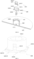


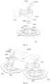


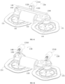
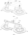


Classifications
-
- A—HUMAN NECESSITIES
- A47—FURNITURE; DOMESTIC ARTICLES OR APPLIANCES; COFFEE MILLS; SPICE MILLS; SUCTION CLEANERS IN GENERAL
- A47L—DOMESTIC WASHING OR CLEANING; SUCTION CLEANERS IN GENERAL
- A47L11/00—Machines for cleaning floors, carpets, furniture, walls, or wall coverings
- A47L11/40—Parts or details of machines not provided for in groups A47L11/02 - A47L11/38, or not restricted to one of these groups, e.g. handles, arrangements of switches, skirts, buffers, levers
-
- A—HUMAN NECESSITIES
- A47—FURNITURE; DOMESTIC ARTICLES OR APPLIANCES; COFFEE MILLS; SPICE MILLS; SUCTION CLEANERS IN GENERAL
- A47L—DOMESTIC WASHING OR CLEANING; SUCTION CLEANERS IN GENERAL
- A47L11/00—Machines for cleaning floors, carpets, furniture, walls, or wall coverings
- A47L11/40—Parts or details of machines not provided for in groups A47L11/02 - A47L11/38, or not restricted to one of these groups, e.g. handles, arrangements of switches, skirts, buffers, levers
- A47L11/4052—Movement of the tools or the like perpendicular to the cleaning surface
- A47L11/4058—Movement of the tools or the like perpendicular to the cleaning surface for adjusting the height of the tool
-
- A—HUMAN NECESSITIES
- A47—FURNITURE; DOMESTIC ARTICLES OR APPLIANCES; COFFEE MILLS; SPICE MILLS; SUCTION CLEANERS IN GENERAL
- A47L—DOMESTIC WASHING OR CLEANING; SUCTION CLEANERS IN GENERAL
- A47L11/00—Machines for cleaning floors, carpets, furniture, walls, or wall coverings
- A47L11/24—Floor-sweeping machines, motor-driven
-
- A—HUMAN NECESSITIES
- A47—FURNITURE; DOMESTIC ARTICLES OR APPLIANCES; COFFEE MILLS; SPICE MILLS; SUCTION CLEANERS IN GENERAL
- A47L—DOMESTIC WASHING OR CLEANING; SUCTION CLEANERS IN GENERAL
- A47L11/00—Machines for cleaning floors, carpets, furniture, walls, or wall coverings
- A47L11/28—Floor-scrubbing machines, motor-driven
-
- A—HUMAN NECESSITIES
- A47—FURNITURE; DOMESTIC ARTICLES OR APPLIANCES; COFFEE MILLS; SPICE MILLS; SUCTION CLEANERS IN GENERAL
- A47L—DOMESTIC WASHING OR CLEANING; SUCTION CLEANERS IN GENERAL
- A47L11/00—Machines for cleaning floors, carpets, furniture, walls, or wall coverings
- A47L11/40—Parts or details of machines not provided for in groups A47L11/02 - A47L11/38, or not restricted to one of these groups, e.g. handles, arrangements of switches, skirts, buffers, levers
- A47L11/4002—Installations of electric equipment
-
- A—HUMAN NECESSITIES
- A47—FURNITURE; DOMESTIC ARTICLES OR APPLIANCES; COFFEE MILLS; SPICE MILLS; SUCTION CLEANERS IN GENERAL
- A47L—DOMESTIC WASHING OR CLEANING; SUCTION CLEANERS IN GENERAL
- A47L11/00—Machines for cleaning floors, carpets, furniture, walls, or wall coverings
- A47L11/40—Parts or details of machines not provided for in groups A47L11/02 - A47L11/38, or not restricted to one of these groups, e.g. handles, arrangements of switches, skirts, buffers, levers
- A47L11/4011—Regulation of the cleaning machine by electric means; Control systems and remote control systems therefor
Definitions
- the present invention relates to the field of household appliances, and in particular, to a cleaning device, and also in particular to a cleaning apparatus.
- the purpose of the present invention is to provide a cleaning device, including: a driving module including a lifting driver;
- the screw mechanism includes a thread groove and a rib which are mated with each other;
- the thread groove is located in the second shaft sleeve, and the rib is located on the first shaft sleeve; and the lifting module further includes a shaft sleeve cover, the shaft sleeve cover is located at a top of the second shaft sleeve, a bottom end of the shaft sleeve cover is provided with a protruding first limit portion, and the first limit portion is located at an end of the thread groove.
- the lifting module further includes a floating assembly;
- the floating assembly includes a floating shaft sleeve and a floating element, the floating element is at least one of a spring, a torsion spring, a shrapnel, an elastic ball, a pneumatic support and a hydraulic support;
- one end of the floating shaft sleeve is fixedly connected with the power output shaft, and the other end of the floating shaft sleeve is connected with the first shaft sleeve;
- the second shaft sleeve is fixedly connected with the cleaning member, or the second shaft sleeve is integrally formed with the cleaning member.
- an elastic element is arranged between the first shaft sleeve and the second shaft sleeve, and the elastic element is at least one of a tension spring, an elastic rope, a torsion spring and a shrapnel; and the elastic element provides the second driving force.
- one end of the floating shaft sleeve is fixedly connected with the second shaft sleeve, and the other end of the floating shaft sleeve is connected with the cleaning member;
- a cross section of the floating shaft sleeve perpendicular to an axial direction is in a polygonal shape, and the first embedded groove is in a polygonal shape mated with the floating shaft sleeve; or, the cross-sectional area of the cleaning member fixing member perpendicular to the axis direction is in a polygonal shape, and the second embedded groove is in a polygonal shape mated with the cleaning member fixing member.
- the driving module further includes a housing, and the housing is sleeved outside the second shaft sleeve.
- the lifting module further includes a damping member, and the damping member is disposed between the second shaft sleeve and the housing.
- the above cleaning device at least one relief hole is disposed on the housing, at least one deformation portion is disposed within the relief hole, and the deformation portion has at least one protrusion protruding inward, and the housing is kept in interference abut with an outer wall surface of the second shaft sleeve through the protrusion; and the protrusion is used as the damping member.
- the deformation portion is in a wave type.
- the controller is electrically or wirelessly connected with the lifting driver and the sensor, respectively.
- the driving module further includes a housing, and the housing is sleeved outside an outer wall of the second shaft sleeve;
- the driving module further includes a housing, and the housing is sleeved outside an outer wall of the second shaft sleeve;
- the light blocking member includes an installation portion and a light blocking portion and a convex column disposed side by side on a sidewall of the installation portion, one end of the biasing member is disposed on the housing, and the other end of the biasing member is disposed on the convex column; and the installation portion is pushed by the second shaft sleeve to drive the light blocking portion to extend into the optical path area.
- one end of the floating shaft sleeve is magnetically connected with the second shaft sleeve through a magnetic assembly, and the other end of the floating shaft sleeve is connected with a cleaning member fixing member for installing the cleaning member, a second floating cavity is formed between them, and the floating element is located within the second floating cavity.
- the magnetic assembly includes a second magnet and a third magnet disposed on the floating shaft sleeve and the second shaft sleeve, respectively, and polarities of ends of the second magnet and the third magnet facing each other are opposite; and the cleaning device further includes a hall sensor for detecting whether the floating shaft sleeve and the second shaft sleeve are installed in place.
- the second shaft sleeve is provided with a first groove area on a side facing the cleaning member fixing member, and an annular second groove area on a side facing away from the cleaning member fixing member; the thread groove or the rib is disposed in the second groove area, a top of the first shaft sleeve is connected with the power output shaft, and a bottom of the first shaft sleeve is embedded in the second groove area; and the third magnet is disposed on a groove bottom of the first groove area; at least one end of the second magnet extends into the first groove area and is magnetically fixed with the third magnet.
- the hall sensor is disposed on a top of the power output shaft, the power output shaft is made of a magnetic conductive material, and an end of the power output shaft is distributed close to the third magnet; or the hall sensor is disposed on the top of the power output shaft, and the power output shaft is made of the magnetic conductive material, and is used as the third magnet, the end of the power output shaft is distributed close to the second magnet.
- the above cleaning device the second magnets is at least two, and correspondingly, the third magnets is at least two; and
- the floating shaft sleeve is connected with the first shaft sleeve, and the floating shaft sleeve is connected with the power output shaft through a magnetic attraction assembly.
- the magnetic attraction assembly includes a first magnet and a fourth magnet, the first magnet is disposed on the floating shaft sleeve, and the fourth magnet is disposed on the power output shaft; polarities of ends of the first magnet and the fourth magnet facing each other are opposite; and the cleaning device further includes a hall sensor for detecting whether the floating shaft sleeve and the power output shaft are installed in place.
- the above cleaning device the power output shaft is made of a magnetic material, and the power output shaft is used as the fourth magnet; and the hall sensor is disposed above a top of the power output shaft.
- the present invention further proves a cleaning apparatus, including: a chassis; and a cleaning device as described above, the cleaning device is installed on the chassis.
- the present invention has the beneficial effects that: the present invention provides a cleaning device and a sweeper, the driving module drives the cleaning member to ascend or descend in a vertical direction by using the lifting module, so as to prevent the cleaning member from polluting a carpet, which may effectively protect the carpet; meanwhile, prevent the cleaning member from causing secondary pollution to the cleaned floor after the sweeper finishes cleaning, and improve the cleaning effect of the sweeper.
- sweepers with different structure forms are used to clean dirt, meanwhile, based on different cleaning requirements, there are different needs for sweeper cleaning devices of sweepers.
- the solution provides a sweeper cleaning device for a sweeper and a sweeper applying the sweeper cleaning device, so as to meet the cleaning requirements of users in different environments.
- a sweeper cleaning device including: a lifting assembly, which includes a first shaft sleeve, a second sleeve portion and an elastic element, where the first shaft sleeve is connected with a power output shaft of the lifting driver, a screw mechanism is formed between the first shaft sleeve and the second sleeve portion, and the elastic element is connected with the first shaft sleeve and the second sleeve portion respectively; and
- the screw mechanism includes a thread groove and a rib mated with each other, and lift angles of the thread groove and the rib are smaller than a self-locking lift angle; and the thread groove is located in the second sleeve portion, and the rib is located on the first shaft sleeve; or, the thread groove is located in the first shaft sleeve, and the rib is located on the second sleeve portion.
- the thread groove is located in the second sleeve portion, and the rib is located on the first shaft sleeve.
- the lifting assembly further includes a shaft sleeve cover, the shaft sleeve cover is located at a top end of the second sleeve portion, and a bottom end of the shaft sleeve cover is provided with a protruding first limit portion, and the first limit portion is located at an end of the thread groove.
- the lifting assembly further includes a floating shaft sleeve and a floating element;
- the floating shaft sleeve includes at least one limit protrusion
- the first shaft sleeve includes at least one first limit groove
- the limit protrusion is mated with the first limit groove
- a cross section of the floating shaft sleeve perpendicular to an axial direction is in a polygonal shape, and the first embedded groove is in a polygonal shape mated with the floating shaft sleeve.
- the driving assembly further includes a housing
- the lifting assembly further includes a damping member
- the damping member is located between the second sleeve portion and the housing; and the damping member is made of a flexible material.
- controller is electrically or wirelessly connected with the lifting driver and the sensor, respectively.
- the present application also provides a sweeper, including a chassis; and a sweeper cleaning device as described above, the sweeper cleaning device is installed on the chassis.
- the present application has the beneficial effects that: the sweeper cleaning device and the sweeper provided in the present application control the descending of the cleaning member by using the screw mechanism through the first driving force of the lifting driver, and control the ascending of the cleaning member by using the screw mechanism through the second driving force of the elastic element, so that the structure is simple, the cost is relative low, which may prevent the cleaning member from polluting the carpet, and protect the carpet effectively; meanwhile, when the sweeper stops operating, the cleaning member automatically elevates, which may prevent the cleaning member from causing secondary pollution to the cleaned floor after the sweeper is cleaned, and improve the cleaning effect of the sweeper.
- sweepers with different structure forms are used to clean dirt, meanwhile, based on different cleaning requirements, there are different needs for sweeper cleaning devices.
- This solution provides a cleaning device for a sweeper and a sweeper applying the cleaning device, so as to meet the cleaning requirements of users in different environments.
- a cleaning mechanism of a sweeper including: a rotary driving module, which includes a rotary driver;
- the bolt lifting structure includes a bolt portion and the lifting block;
- the lifting block is connected with the case of the rotary driver, or the lifting block is connected with the power output shaft of the rotary driver.
- the power output shaft of the rotary driver is at least one, and the lifting block is at least one;
- the cleaning module further includes a sleeve portion, a floating shaft sleeve and a floating element;
- the floating element is at least one of a spring, a torsion spring, a shrapnel, an elastic ball, a pneumatic support and a hydraulic support.
- the floating shaft sleeve further includes at least one limit portion, and the sleeve portion further includes at least one limit groove, and the limit portion is mated with the limit groove in one-to-one correspondence.
- a cross section of the floating shaft sleeve perpendicular to an axial direction is in a polygonal shape, and the first embedded groove is a polygonal groove mated with the floating shaft sleeve.
- the present application also provides a sweeper including a cleaning mechanism of a sweeper as described above.
- the present application has the beneficial effects that: in the cleaning mechanism of the sweeper and the sweeper provided in the present invention, the first driving force of the output shaft of the elevating driver drives the cleaning tray to move in a vertical direction by using the lifting block, so that the structure is simple, the cost is relative low, which may prevent the cleaning member from polluting the carpet, and protect the carpet effectively; meanwhile, prevent the cleaning tray from causing secondary pollution to the cleaned floor after the sweeper finishes cleaning, and improve the cleaning effect of the sweeper.
- sweepers with different structure forms are used to clean dirt, meanwhile, based on different cleaning requirements, there are different needs for sweeper cleaning devices.
- This solution provides a sweeper cleaning device for a sweeper and a sweeper applying the sweeper cleaning device, so as to meet the cleaning requirements of users in different environments.
- a liftable sweeper cleaning mechanism including:
- the lifting structure includes a rack and a gear mated with the rack; and the rack is connected with the rotary driving shaft, and the gear is connected with the power output end of the lifting driver.
- the elevating driver is not less than one, the rotary driving shaft is at least one, and the rack is at least one;
- the rack is connected with the at least one rotary driving shaft through the first connection rod, and the rack is disposed in a central area of the first connection rod, and distances from the rack to each rotary driving shaft are equal.
- the lifting structure includes a flexible rope and a power output shaft of the elevating driver, one end of the flexible rope is connected with the rotary driving shaft, and the other end of the flexible rope is connected with the power output shaft of the elevating driver.
- the elevating driver is at least one, the rotary driving shaft is at least one, and the flexible rope is at least one;
- the flexible rope is connected with the at least one rotary driving shaft through the second connection rod, and a connection point between the flexible rope and the second connection rod is located in a central area of the second connection rod, and distances from the connection point to each rotary driving shaft are equal.
- the present application provides a sweeper, including a liftable sweeper cleaning mechanism as described above.
- the present application has the beneficial effects that: the present application provides a liftable sweeper cleaning mechanism and a sweeper, the elevating driver drives the rotary driving module to ascend and descend in a vertical direction through the lifting structure, thereby to realize the ascending and descending of the cleaning tray in the vertical direction, which may prevent the cleaning tray from polluting a carpet and effectively protect the carpet, and meanwhile, may prevent the cleaning tray from causing secondary pollution to the cleaned floor after the sweeper finishes cleaning, and improve the cleaning effect of the sweeper.
- sweepers with different structure forms are used to clean dirt, meanwhile, based on different cleaning requirements, there are different needs for sweeper cleaning devices.
- This solution provides a cleaning mechanism of a sweeper and a sweeper applying the cleaning mechanism, so as to meet the cleaning requirements of users in different environments.
- a cleaning mechanism of a sweeper including:
- a first embedded groove 1412 is provided within the first sleeve portion, and a cross section of the first embedded groove 1412 is in a polygonal shape; and a cross section of the floating shaft sleeve is in a polygonal shape, and a lower portion of the floating shaft sleeve is embedded in the first embedded groove 1412.
- a first floating cavity is formed between the floating shaft sleeve and the first embedded groove 1412; a floating element is disposed within the first floating cavity, and the floating element is at least one of a spring, a torsion spring, a shrapnel, an elastic ball, a pneumatic support and a hydraulic support.
- a periphery of the floating shaft sleeve is arranged with a third limit portion, and a periphery of the first sleeve portion is provided with a first limit groove, and the third limit portion is adapted to the first limit groove.
- a side end of the third limit portion is arranged with a guide surface.
- the floating shaft sleeve is detachably connected with the rotary driving shaft.
- a top of the floating shaft sleeve is provided with a third embedded groove, and a cross section of the third embedded groove is in a polygonal shape; and a cross section of the rotary driving shaft is in a polygonal shape, and a lower portion of the rotary driving shaft is detachably sleeved in the third embedded groove.
- a fifth magnet is disposed within the third embedded groove.
- the present utility model provides a sweeper including a cleaning mechanism of a sweeper as described above.
- the present utility model has the beneficial effects that: the present utility model provides a cleaning mechanism of a sweeper and a sweeper, the rotary driving shaft is connected with the first sleeve portion through a floating shaft sleeve, so that the cleaning tray floats correspondingly with different terrain on the floor, the cleaning tray may be closely attached to the uneven floor, the sweeper may be adapted to different terrain, which further improve the cleaning effect, and also enhance the obstacle-crossing function of the cleaning tray.
- a cleaning apparatus such as a mopping machine, is used for mopping and covering the surface to be cleaned.
- Its cleaning parts are the dishcloth tray and the dishcloth disposed on the dishcloth tray, but the dishcloth tray is usually disposed at a bottom of the machine body, which may not realize the lifting effect, during the process of returning to a cleaning station after finishing cleaning, the dishcloth always contacts the floor, which may cause secondary pollution to the floor.
- the dishcloth may hinder the movement of the cleaning apparatus because of the large friction between the dishcloth and the carpet, and meanwhile may pollute the carpet, which is not conducive to the smooth cleaning operation of the cleaning apparatus.
- the present application provides a cleaning mechanism of a magnetic lifting dishcloth tray, and the lifting control of the dishcloth tray is more flexible.
- the present application provides a cleaning mechanism suitable for a cleaning apparatus, including:
- the electromagnetic assembly is approximately uniformly arranged around a central axis of the dishcloth tray, and the magnetic attraction part is uniformly distributed right below the electromagnetic assembly.
- the electromagnetic assembly is configured to be in an annular shape
- the magnetic attraction part is an annular iron ring consistent with the annular shape of the electromagnetic assembly
- the electromagnetic assembly is coaxially disposed with the magnetic attraction part
- a number of the electromagnetic assembly is multiple, the plurality of electromagnetic assemblies are approximately uniformly arranged around the central axis of the dishcloth tray, and the magnetic attraction parts and the electromagnetic assemblies are disposed in one-to-one correspondence in an up-and-down direction.
- the cleaning mechanism further includes a control unit the control unit includes a switch circuit for cutting off and connecting the electromagnetic assembly and the power supply to control a generation and extinction of the electromagnetic field.
- the magnetic attraction part is a permanent magnet
- the control unit further includes a reverse circuit for switching a current direction in the electromagnetic assembly to change a direction of the electromagnetic field to generate a magnetic field force pushing against the magnetic attraction part.
- the connecting structure includes a connecting member and a fixing seat floatingly sleeved outside the connecting member, the dishcloth tray is disposed on the fixing seat and located below the fixing seat, and an upper end of the biasing member abuts against the connecting member and a lower end abuts against the dishcloth tray.
- the connecting member includes an annular cavity with an opening at a lower end, and the biasing member is disposed within the annular cavity.
- the connecting member includes an installation shaft hole for inserting a driving shaft of the cleaning apparatus, and the connecting member is driven to rotate by the driving shaft to drive the dishcloth tray to rotate.
- a permanent magnet is fixedly disposed on the connecting member, and an iron block is fixedly disposed below the driving shaft, and the permanent magnet is located at a bottom of the installation shaft hole, and is right facing the iron block.
- an outer side surface of the connecting member and an inner wall surface of the fixing seat are provided with guide structures mated with each other, and the guide structures are used for limiting the fixing seat to slide along an axial direction of the connecting member.
- the present application also provides a cleaning mechanism including a cleaning mechanism provided in any one of the above embodiments.
- the cleaning mechanism controls the generation and extinction of the electromagnetic field by turning on and off the electromagnetic assembly, so as to generate magnetic attraction to the magnetic attraction part to realize the elevating of the dishcloth tray.
- the electromagnetic assembly is powered off, and the electromagnetic field disappears, the dishcloth tray is pushed downward to the mopping position by the biasing member, so as to realize the lifting control of the dishcloth tray.
- the electromagnetic assembly is adopted to control the elevating of the dishcloth tray by electromagnetic attraction, so that the dishcloth tray may ascend or descend according to the actual demand, and the control is more flexible.
- the lifting control of the dishcloth tray can effectively avoid a problem of secondary pollution caused by a second mopping of the surface that has been mopped by the dishcloth, and the floor cleaning effect is better.
- the lifting of the dishcloth may avoid the contact between the dishcloth and such floor and avoid the adverse impact of such floor on cleaning work.
- the cleaning apparatus may be elevated to move to a specific position after the dishcloth is stained with dirt to perform the operation of replacing the dishcloth or cleaning the dishcloth.
- the present invention relates to a cleaning device, including:
- the thread groove 1421 is located in the second shaft sleeve 142 and the rib 1411 is located in the first shaft sleeve 141.
- the rib 1411 is in a strip shape, and in another embodiment of the present invention, the rib 1411 is in a threaded shape.
- the specific setting of the shape of the rib 1411 may be selected by the workers according to the actual situation.
- the lifting driver 121 drives the power output shaft 122 to rotate in a forward direction, thereby drives the first shaft sleeve 141 to rotate in the forward direction, and further controls the rib 1411 on the first shaft sleeve 141 to rotate in the forward direction along the thread grooves 1421 on the second shaft sleeve 142, so that a relative displacement occurs between the first shaft sleeve 141 and the second shaft sleeve 142, and the cleaning member 131 is in contact with the floor for cleaning operation.
- the lifting driver 121 drives the power output shaft 122 to rotate in a reverse direction, further controls the rib 1411 on the first shaft sleeve 141 to rotate in the reverse direction along the thread groove 1421 on the second shaft sleeve 142, so that a relative displacement occurs between the first shaft sleeve 141 and the second shaft sleeve 142 again, and the cleaning member 131 performs an ascending motion relative to the lifting driver 121, disengages from the floor, thereby realizes an elevating operation of the cleaning member 131.
- the self-locking lift angle is determined according to the static friction factor between materials.
- the lift angles of the thread groove 1421 and the rib 1411 are the same, and the lift angles of the thread groove 1421 and the rib 1411 are smaller than the self-locking lift angle determined based on the static friction factor, so as to prevent the cleaning member 131 from rotating and descending under the action of its own gravity when it ascends to a highest position, which may effectively limit and fix the cleaning member 131.
- the cleaning member 131 is located at a lowest position during normal operation, and at this time, a distance between the cleaning member 131 and the floor is H, and the distance H is 1 mm-3 mm.
- the cleaning member 131 is located at the highest position, and the distance between the cleaning member 131 and the floor is D, the distance D is 5 mm-9 mm, and an elevating height of the cleaning member 131 is 4 mm-6 mm.
- the cleaning member 131 is located at the lowest position during normal operation, and a distance between the cleaning member 131 and the floor is H, and the distance H is 1.5 mm.
- the cleaning member 131 is located at the highest position, and the distance between the cleaning member 131 and the floor is D, the distance D is 6.5 mm, and an elevating height of the cleaning member 131 is 5 mm.
- the workers may adjust the elevating height of the cleaning member 131 by selecting setting the thread groove 1421 with different number of turns according to the actual situation, so that the sweeper may be applicable to different scenes and has a certain universality.
- each thread groove 1421 There is a certain gap provided between each thread groove 1421 and a corresponding rib 1411, and lubricating grease is provided in each thread groove 1421, so that the second shaft sleeve 142 may rotate smoothly.
- the lifting module 14 further includes a shaft sleeve cover 143, the shaft sleeve cover 143 is located at a top of the second shaft sleeve 142, and there is a protruding first limit portion 1431 at a bottom of the shaft sleeve cover 143, and the first limit portion 1431 is located at an end of the thread groove 1421.
- the other end of the thread groove 1421 is provided with a second limit portion 1422;
- the power output shaft 122 is fixedly connected with the first shaft sleeve 141; or, the power output shaft 122 is in floating connection with the first shaft sleeve 141.
- the power output shaft 122 is in floating connection with the first shaft sleeve 141.
- the lifting module 14 further includes a floating assembly 144;
- the floating assembly 144 includes a floating shaft sleeve 1441 and a floating element, and the floating element is at least one of a spring, a torsion spring, a shrapnel, an elastic ball, a pneumatic support and a hydraulic support;
- the floating shaft sleeve 1441 is connected with the first shaft sleeve 141, and the floating shaft sleeve 1441 is connected with the power output shaft 122.
- the floating element is a spring
- the floating element in another embodiment of the present invention, is a torsion spring, and in yet another embodiment of the present invention, the floating element is a shrapnel.
- the specific setting of the floating element may be selected by the workers according to the actual situation.
- a pressure range of the floating element is 5 N-10 N, and a floating stroke of the cleaning member 131 may be specifically set according to the actual situation.
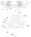
- one end of the floating shaft sleeve 1441 is fixedly connected with the power output shaft 122, and the other end of the floating shaft sleeve 1441 is connected with the first shaft sleeve 141; and the first shaft sleeve 141 includes a first embedded groove 1412, and the floating shaft sleeve 1441 is disposed within the first embedded groove 1412; the floating shaft sleeve 1441 includes at least one first limit protrusion 14411, a sidewall of the first embedded groove 1412 includes at least one first limit groove 1413, and the first limit protrusion 14411 is mated with the first limit groove 1413.
- a first floating cavity 1442 is formed between the floating shaft sleeve 1441 and the first shaft sleeve 141, and the floating element is located within the first floating cavity 1442.
- the floating shaft sleeve 1441 and the first shaft sleeve 141 are limited and fixed by the mating of the first limit protrusion 14411 and the first limit groove 1413.
- a side end of the first limit protrusion 14411 is provided with a guide surface 144111, the guide surface 144111 is a transitional structure of the first limit protrusion 14411.
- the guide surface 144111 may guide the first limit protrusion 14411 to slide to the first limit groove 1413, so as to facilitate the shaft sleeve 1441 to be sleeved within the first embedded groove 1412.
- the pressure between the cleaning member 131 and the floor is increased, and the cleaning effect of the cleaning member 131 is improved, and meanwhile, the cleaning member 131 floats correspondingly with different terrain on the floor, so that the dishcloth on the cleaning member 131 may be closely attached to the uneven floor, the sweeper may be adapted to different terrain, the cleaning effect is further improved, and an obstacle-crossing function of the cleaning member 131 is enhanced.
- a cross section of the floating shaft sleeve 1441 perpendicular to an axial direction is in a polygonal shape, and the first embedded groove 1412 is in a polygonal shape mated with the floating shaft sleeve; and in a specific embodiment of the present invention, a cross section of the floating shaft sleeve 1441 perpendicular to the axial direction is in a quadrangular shape, and the first embedded groove 1412 is in a quadrangular shape mated with the floating shaft sleeve 1441; in another specific embodiment of the present invention, the cross section of the floating shaft sleeve 1441 perpendicular to the axial direction is in a pentagonal shape, and the first embedded groove 1412 is in a pentagonal shape mated with the floating shaft sleeve 1441; and in yet another specific embodiment of the present invention, the cross section of the floating shaft sleeve 1441 perpendicular to the axial direction is in a hexagonal shape, and the first embedded groove
- the specific setting of the cross sections of the floating shaft sleeve 1441 and the first embedded groove 1412 perpendicular to the axis direction may be selected by the workers according to the actual situation.
- the polygonal floating shaft sleeve 1441 and the first embedded groove 1412 are a limit structure, and the mating of the floating shaft sleeve 1441 and the first embedded groove 1412 is used to limit and fix a lower portion of the floating shaft sleeve 1441 with the first shaft sleeve 141 relative to each other, so that the lower portion of the floating shaft sleeve 1441 is firmly embedded with the first shaft sleeve 141.
- the floating shaft sleeve 1441 is connected with the first shaft sleeve 141, and the floating shaft sleeve 1441 is connected with the power output shaft 122 through a magnetic attraction assembly, and a floating cavity is formed between a bottom of the floating shaft sleeve 1441 and the first shaft sleeve 141 for the installation of the floating element.
- the magnetic attraction assembly includes a first magnet 1444 and a fourth magnet, the first magnet 1444 is disposed on the floating shaft sleeve 1441, and the fourth magnet is disposed on the power output shaft 122; polarities of ends of the first magnet 1444 and the fourth magnet facing each other are opposite; the cleaning device further includes a hall sensor (not shown in the drawings) fixedly disposed relative to one of the first magnet and the fourth magnet, and it is used to detect whether the floating shaft sleeve 1441 and the power output shaft 122 are installed in place.
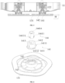
- the second shaft sleeve 142, the first shaft sleeve 141, the floating shaft sleeve 1441, a cleaning member fixing member 1311 and the first magnet 1444 are pre-installed to form a cleaning member combination, and then the cleaning member combination is integrally installed on the power output shaft 122, that is, the first magnet 1444 and the fourth magnet are magnetically fixed, when the first magnet 1444 and the fourth magnet are magnetically attracted, the hall sensor detects a magnetic flux of a magnetic field loop formed after the magnetic attraction of the first magnet 1444 and the fourth magnet, and feeds it back to the controller, the controller compares this magnetic flux with a preset magnetic flux.
- the detected magnetic flux reaches the preset magnetic flux, it indicates that the cleaning member combination and the power output shaft 122 are installed in place. If the detected magnetic flux does not reach the preset magnetic flux, it indicates that the cleaning member combination and the power output shaft 122 are not installed in place. That is, it is used for detecting whether the cleaning member combination is installed in place with the power output shaft 122.
- the power output shaft 122 is made of magnetic material, and the power output shaft 144 is used as the fourth magnet; the hall sensor is disposed above a top of the power output shaft. Preferably, the hall sensor is disposed right above the top of the power output shaft 122 to improve the detection accuracy.
- the floating shaft sleeve 1441 is provided with a relief hole, so that the magnetic attraction of the first magnet and the fourth magnet or the power output shaft is firmer.
- above second shaft sleeve 142 may be integrally formed on the cleaning member fixing member 1311, which further facilitates the pre-installation of the cleaning member combination.
- the second shaft sleeve 142 is detachably connected with the cleaning member fixing member 1311, for example, by snap or screw connection.
- the floating shaft sleeve 1441 further includes a third embedded groove 14414, and the other end of the power output shaft 122 is disposed in the third embedded groove 14414 and connected with the floating shaft sleeve 1441.
- the power output shaft 122 is connected with the third embedded groove 14414 in a snap manner, or the power output shaft 122 is magnetically connected with the third embedded groove 14414 through the first magnet 1444.
- the power output shaft 122 is magnetically connected with the third embedded groove 14414 through the first magnet 1444.
- the first magnet 1444 may be arranged at a bottom of the third embedded groove 14414, or the first magnet 1444 is arranged at a circumferential area inside the third embedded groove 14414.
- the specific setting of a position of the first magnet 1444 may be selected by the workers according to the actual situation.
- a cross section of the power output shaft 122 perpendicular to an axial direction is in a polygonal shape, and the third embedded groove 14414 is in a polygonal shape mated with the power output shaft 122.
- the cross section of the power output shaft 122 perpendicular to the axial direction is in a quadrangular shape, and the third embedded groove 14414 is in a quadrangular shape mated with the power output shaft 122.
- the cross section of the power output shaft 122 perpendicular to the axial direction is in a pentagonal shape, and the third embedded groove 14414 is in a pentagonal shape mated with the power output shaft 122; in yet another specific embodiment of the present invention, the cross section of the power output shaft 122 perpendicular to the axial direction is in a hexagonal shape, and the third embedded groove 14414 is in a hexagonal shape mated with the power output shaft 122.
- the specific setting of the cross sections of the power output shaft 122 and the third embedded groove 14414 perpendicular to the axis direction may be selected by the workers according to the actual situation.
- a polygonal third embedded groove 14414 and the power output shaft 122 are a limit structure, and the mating of the third embedded groove 14414 and the power output shaft 122 is used to preliminarily limit and fix the power output shaft 122 of the lifting driver 121 and the floating shaft sleeve 1441; meanwhile, the first magnet 1444 is disposed inside the third embedded groove 14414, and the power output shaft 122 and the floating shaft sleeve 1441 are further limited and fixed by the first magnet 1444, so that the power output shaft 122 and the floating shaft sleeve 1441 are firmly embedded, and it is convenient to easily detach and separate the power output shaft 122 and the floating shaft sleeve 1441, and it is finally convenient to detach the cleaning member 131.
- the worker controls different initial positions of the cleaning member 131 by controlling different assembly directions of the power output shaft 122 and the floating shaft sleeve 1441, and the floating shaft sleeve 1441 and the first shaft sleeve 141.
- a rotation speed of the power output shaft 122 of the lifting driver 121 is different, and the magnetic force of the first magnet 1444 is different.
- the first magnet 1444 with a relatively large magnetic force may be selected; and when the rotation speed of the power output shaft 122 of the lifting driver 121 is relatively low, the first magnet 1444 with a relatively small magnetic force may be selected. According to the rotation speed of the power output shaft 122 of the lifting driver 121, the first magnet 1444 with a specific magnetic force is selected to ensure that the floating shaft sleeve 1441 is stably connected with the power output shaft 122 of the lifting driver 121.
- the second shaft sleeve 142 is fixedly connected with the cleaning member 131, or the second shaft sleeve 142 is integrally formed with the cleaning member 131.
- the specific setting of a connection manner between the second shaft sleeve 142 and the cleaning member 131 may be selected by the workers according to the actual situation.
- the lifting module 14 further includes a damping member 146
- the driving module further includes a housing 123
- the damping member 146 is disposed between the second shaft sleeve 142 and the housing 123.
- the damping member 146 is made of a flexible material.
- the damping member 146 is disposed between the second shaft sleeve 142 and the housing 123 to avoid the friction between the second shaft sleeve 142 and the housing 123, and prolong a service life of the second shaft sleeve 142; meanwhile, the damping member 146 is made of a flexible material, which results in a friction between the damping member 146 and the housing 123, plays a hindering role of hindering the second shaft sleeve 142 from reaching the same rotation speed as the first shaft sleeve 141, extends the time for the second shaft sleeve 142 to reach the same rotation speed as the first shaft sleeve 141, so that no matter how the rotation speed of the power output shaft 122 of the lifting driver 121 is set, as long as the power output shaft 122 rotates normally, it may rotate relative to the second shaft sleeve 142, and the cleaning member 131 may ascend or descend under the action of a screw mechanism.
- controller is electrically or wirelessly connected with the lifting driver 121 and the sensor respectively.
- the senor is used to inductively identify the carpet.
- the sensor senses the existence of the carpet, the sensor sends a feedback signal to the controller, after receiving the feedback signal, the controller sends a control instruction to the lifting driver 12 according to a feedback result, the first driving force of the power output shaft 122 of the lifting driver 121 drives the cleaning member 131 to perform the ascending motion relative to the lifting driver 121, so as to realize the elevating function of the cleaning member 131, and perform avoidance operations on the carpet.
- the cleaning member 131 is located at the highest position.
- the controller sends a control instruction to the lifting driver 121 to control the power output shaft 122 of the lifting driver 121 to start rotating in a forward direction, thereby drives the first shaft sleeve 141 to rotate in a forward direction, and further controls the rib 1411 on the first shaft sleeve 141 to rotate reversely along the thread groove 1421 of the second shaft sleeve 142, and meanwhile, under the action of the damping member 146, a relative displacement occurs between the first shaft sleeve 141 and the second shaft sleeve 142, and the cleaning member 131 performs a descending motion relative to the lifting driver 121, and the cleaning member 131 contacts the floor for cleaning operation; and
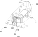
- the elastic element 145 is a tension spring, in another embodiment of the present invention, the elastic element 145 is a torsion spring, and in yet another embodiment of the present invention, the elastic element 145 is a shrapnel.
- the specific setting of the elastic element 145 may be selected by the workers according to the actual situation.
- the cleaning member 131 further includes a second connection portion 1312
- the first shaft sleeve 141 further includes a first connection portion 1414
- a first end and a last end of the elastic element 145 are connected with the first connection portion 1414 and the second connection portion 1312, respectively.
- the controller sends a control instruction to the lifting driver 121, and the lifting driver 121 drives the power output shaft 122 to rotate according to the control instruction, thereby drives the first shaft sleeve 141 to rotate, and further controls the rib 1411 on the first shaft sleeve 141 to rotate along the thread groove 1421, meanwhile, under the action of the damping member 146, a relative displacement occurs between the first shaft sleeve 141 and the second shaft sleeve 142, the cleaning member 131 descends in vertical direction, the dishcloth on the cleaning member 131 contacts the floor to mop the floor, and meanwhile, the elastic element 145 is in a stretched state;
- the sensor when the sensor senses the existence of carpet, the sensor sends a feedback signal to the controller, and after receiving the feedback signal, the controller sends a control instruction to the lifting driver 121 according to the feedback result, so as to control the lifting driver 121 to stop operating, thereby stop the stretching operation of the elastic element 145, under the action of the second driving force of the elastic element 145, the rib 1411 rotates along the thread groove 1421 again, and meanwhile, under the action of the damping element 146, a relative displacement between the first shaft sleeve 141 and the second shaft sleeve 142 occurs again, and the cleaning member 131 ascends in the vertical direction and disengages from the floor, thereby realizes the elevating function of the dishcloth on the cleaning member 131, and further to perform avoidance operations on the carpet; or, when the sweeper finishes operating, the controller sends a control instruction to the lifting driver 121 to control the lifting driver 121 to stop operating, so as to stop the stretching operation of the elastic element 145, and under the action of
- one end of the floating shaft sleeve 1441 is fixedly connected with the second shaft sleeve 142, and the other end of the floating shaft sleeve 1441 is connected with the cleaning member 131;
- the floating element By disposing the floating element between the floating shaft sleeve 1441 and the cleaning member 131, a pressure between the cleaning member 131 and the floor is increased, and the cleaning effect of the cleaning member 131 is improved, meanwhile, the cleaning member 131 floats correspondingly with different terrain on the floor, so that the dishcloth on the cleaning member 131 may be closely attached to the uneven floor, the sweeper may be adapted to different terrain, the cleaning effect is further improved, and the obstacle-crossing function of the cleaning member 131 is enhanced.
- a cross sectional area of the cleaning member fixing member 1311 perpendicular to the axial direction is in a polygonal shape, and the second embedded groove 14412 is in a polygonal shape mated with the cleaning member fixing member 1311.
- the cross section of the cleaning member fixing member 1311 perpendicular to the axial direction is in a quadrangular shape, and the second embedded groove 14412 is in a quadrangular shape mated with the cleaning member fixing member 1311; in another specific embodiment of the present invention, the cross section of the cleaning member fixing member 1311 perpendicular to the axial direction is in a pentagonal shape, and the second embedded groove 14412 is in a pentagonal shape mated with the cleaning member fixing member 1311; and in yet another specific embodiment of the present invention, the cross section of the cleaning member fixing member 1311 perpendicular to the axial direction is in a hexagonal shape, and the second embedded groove 14412 is in a hexagonal shape mated with the cleaning member fixing member 1311.
- a polygonal second embedded groove 14412 and cleaning member fixing member 1311 are a limit structure, and the mating of the second embedded groove 14412 and the cleaning member fixing member 1311 is used to limit and fix the cleaning member 131 and the floating shaft sleeve 1441.
- the floating sleeve 144 includes a fixing portion 14415, and the second shaft sleeve 142 includes a fourth embedded groove 1423, and the fixing portion 14415 is disposed within the fourth embedded groove 1423.
- a cross-sectional area of the fixing portion 14415 perpendicular to the axial direction is in a polygonal shape, and the fourth embedded groove 1423 is in a polygonal shape mated with the fixing portion.
- the cross section of the fixing portion 14415 perpendicular to the axial direction is in a quadrangular shape, and the fourth embedded groove 1423 is in a quadrangular shape mated with the fixing portion 14415; in another specific embodiment of the present invention, the cross section of the fixing portion 14415 perpendicular to the axial direction is in a pentagonal shape, and the fourth embedded groove 1423 is in a pentagonal shape mated with the fixing portion 14415; and in yet another specific embodiment of the present invention, the cross section of the fixing portion 14415 perpendicular to the axial direction is in a hexagonal shape, and the fourth embedded groove 1423 is in a hexagonal shape mated with the fixing portion 14415.
- a polygonal fourth embedded groove 1423 and fixing portion 14415 are a limit structure, and the mating of the fourth embedded groove 1423 and the fixing portion 14415 is used to preliminarily limit and fix the second shaft sleeve 142 and the floating shaft sleeve 1441.
- second shaft sleeve 142 and the floating shaft sleeve 1441 are connected in a snap manner. Or, the second shaft sleeve 142 and the floating shaft sleeve 1441 are connected in a magnetic attraction manner.
- the second shaft sleeve 142 and the floating shaft sleeve 1441 are connected in a magnetic attraction manner.
- a second magnet 1445 is arranged on the floating shaft sleeve 1441, and the second shaft sleeve 142 and the floating shaft sleeve 1441 are further limited and fixed by the second magnet 1445, so that the second shaft sleeve 142 and the floating shaft sleeve 1441 are firmly embedded, and it is convenient to detach and separate the second shaft sleeve 142 and the floating shaft sleeve 1441, and finally it is convenient to detach the cleaning member 131.
- one end of the floating shaft sleeve 1441 is magnetically connected with the second shaft sleeve 142 through a magnetic assembly, and the other end of the floating shaft sleeve 1441 is connected with the cleaning member fixing member 1311 for installing the cleaning member, and a second floating cavity is formed between them, and the floating element is located within the second floating cavity.
- the magnetic assembly includes a second magnet 1445 and a third magnet 151 disposed on the floating shaft sleeve 1441 and the second shaft sleeve 142, respectively. Polarities of ends of the second magnet 1445 and the third magnet 151 facing each other are opposite, and the floating shaft sleeve 1441 is detachably and fixedly connected with the second shaft sleeve 142 through mutual attraction of the second magnet 1445 and the third magnet 151.
- the cleaning device further includes a hall sensor (not shown in the drawings) fixedly disposed relative to one of the second magnet and the third magnet and used to detect whether the floating shaft sleeve 1441 and the second shaft sleeve 142 are installed in place.
- a hall sensor (not shown in the drawings) fixedly disposed relative to one of the second magnet and the third magnet and used to detect whether the floating shaft sleeve 1441 and the second shaft sleeve 142 are installed in place.
- the floating shaft sleeve 1441, the cleaning member fixing member 1311 and the second magnet 1445 are pre-installed to form a combination, and then the second magnet 1445 at a top of the entire combination is fixedly connected with the third magnet 151, at this time, the hall sensor detects that a magnetic flux is formed after the magnetic attraction of the second magnet and the third magnet and feeds it back to the controller, and the controller compares this magnetic flux with a preset magnetic flux.
- the detected magnetic flux reaches the preset magnetic flux, it indicates that the combination and the second shaft sleeve are installed in place. If the detected magnetic flux does not reach the preset magnetic flux, it indicates that the combination and the second shaft sleeve are not installed in place.
- a side of the second shaft sleeve 142 facing the cleaning member fixing member 1311 is provided with a first groove area, i.e., a side of the above fourth embedded groove 1423facing away from the cleaning member fixing member 1311 is provided with an annular second groove area 1425; the thread groove 1421 or the rib 1411 is disposed in the second groove area 1425, a top of the first shaft sleeve 141 is connected with the power output shaft 122, and a bottom of the first shaft sleeve 141 is embedded within the second groove area 1425.
- a cross section of the first shaft sleeve is inverted U-shaped.
- the third magnet 151 is disposed on a groove bottom of the first groove area; at least the second magnet 1445 extends into the first groove area and is magnetically fixed with the third magnet 1425, so that the whole second shaft sleeve 142, the first shaft sleeve 141 and the power output shaft 122 are compact in structure.
- the above hall sensor may be disposed in the first groove area, and the hall sensor is closer to the groove bottom of the first groove area than the third magnet 151, that is, the hall sensor is located at a groove bottom of the first groove area.
- the hall sensor may also be disposed on the floating shaft sleeve 1441, and the second magnet 1445 is closer to the groove bottom of the first groove area than the hall sensor.
- the hall sensor is disposed on the top of the power output shaft 122, the power output shaft 122 is made of magnetic conductive material, and an end of the power output shaft 122 is distributed to be close to and right face the third magnet 151.
- the power output shaft 122 is made of a magnetic conductive material and is directly used as the third magnet, and there is no need to dispose the third magnet 151 in the first groove area.
- the groove bottom of the first groove area is provided with an opening or a relief hole, which is convenient for the magnetic attraction fixation of the third magnet and the second magnet.
- FIG. 25 and FIG. 26 there are at least two second magnets 1445, and correspondingly, there are at least two third magnets 151.
- a bottom edge of the floating shaft sleeve 1441 is provided with an outer edge 1446 protruding outward, and the outer edge 1446 is distributed opposite to a bottom of the second groove region 1425.
- At least one third magnets 151 is disposed on the bottom of the second groove region 1425, and at least one second magnets 1445 is disposed on the outer edge 1446, and the second magnets 1445 are magnetically connected with the third magnets 151, which further increases the connection firmness between the second shaft sleeve 142 and the floating shaft sleeve 1441.
- annular flange 1448 is disposed on and edge of the outer edge, and correspondingly, as shown in FIG. 27 , a bottom of the second shaft sleeve 142 is provided with an extension portion 1426, and the extension portion 1426 abuts on the outer edge, so that the annular flange, the outer edge and an outer wall of the extension portion 1426 are enclosed to form an annular groove, and the second magnet 1445 is in an annular shape and disposed in the annular groove.
- the second groove area of the second shaft sleeve 142 is provided with an annular hole 1427, and the third magnet 151 is embedded within the annular hole 1427, so that the third magnet and the second magnet are oppositely distributed.
- the above annular flange and the above extension may not be disposed, and the third magnet and the second magnet are directly disposed on the bottom of the second shaft sleeve and the top of the floating shaft sleeve, respectively.
- the cleaning member fixing member 1311 and the floating shaft sleeve are connected in a snap manner.
- a sidewall of the floating shaft sleeve 1441 is provided with at least one mating hole 1447, and a top of the cleaning member fixing member 1311 extends into a bottom cavity of the floating shaft sleeve, and the top or sidewall of the cleaning member fixing member 1311 is provided with a snap, and the snap is hooked on the mating hole 1447 to realize a detachable connection of the two.
- Positions of the snap and the mating hole may be reversed, or they may be fixedly connected in other ways, such as magnetic attraction.
- the floating shaft sleeve 1441 is also molded on the cleaning member fixing member 1311.
- the lifting module 14 further includes a damping member 146
- the driving module further includes a housing 123
- the damping member 146 is disposed between the second shaft sleeve 142 and the housing 123.
- the damping member 146 is an O-shaped sealing ring, and a sealing ring fixing groove 1424 is disposed on the second shaft sleeve 142, and the damping member 146 is arranged in the sealing ring fixing groove 1424.
- the driving module further includes a housing 123, the housing 123 is sleeved outside the second shaft sleeve 143.
- the housing 123 is provided with at least one relief hole 1231, and at least one deforming part 1232 is disposed in the relief hole 1231, the deforming part 1232 has at least one protrusion protruding inward, and the housing 123 is kept an interference abutment with the outer wall surface of the second shaft sleeve through the protrusion.
- the protrusion forms elastic interference abutment with the outer wall of the second shaft sleeve, which ensures that the protrusion always maintains a certain friction force with the outer wall of the second shaft sleeve and plays a damping role.
- the housing and the deformation portion 1232 are integrally formed and made of a plastic material, for example, the plastic may be POM, pp plastic, etc.
- the relief hole 1231 on the housing may be set to be one or two or more, and when the relief hole 1231 is set to be multiple, optimally, a plurality of relief holes 1231 are evenly distributed on a circle of an outer wall of the housing 123.
- the deformation portion 1232 disposed within each relief hole 1231 may be one, two or more, and at least one protrusion is disposed on the deformation portions 1232.
- the deformation portion 1232 may be in a wave type, and a peak position of the wave type is just a protrusion.
- the deformation portion may be not only in a wave shape, but also in other shapes, such as in an M type, a V type, or other cambered surfaces or curved surfaces.
- a plurality of hanging ears 1233 distributed at intervals is also disposed on the top of the housing 123, and the housing is detachably connected with the chassis 11 of the sweeper or cleaning apparatus through the hanging ears 1233, and the hanging ears may be connected with the chassis 11 through a snap, a magnetic connection or other detachable connection manners.
- FIG. 20 and FIG. 21 further includes a sensor and a controller, and the controller is electrically or wirelessly connected with the lifting driver 121 and the sensor, respectively.
- the driving module further includes a housing 123, the housing 123 is sleeved outside the outer wall of the second shaft sleeve 142.
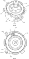
- the sensor includes a light emitter 1471 and a light receiver 1472 which are oppositely disposed on the housing 123, and an optical path area is formed between the light emitter 1471 and the light receiver 1472.
- the senor feeds back a signal to the controller that the second shaft sleeve 142 ascends in place, that is, a signal that the cleaning member ascends in place, and according to this signal, the controller outputs a control signal to control the lifting driver to stop moving.
- the controller outputs a control signal to control the lifting driver to stop moving.
- the driving module further includes a housing 123, a light blocking member 148 and a biasing member 149, and the housing is sleeved outside the outer wall of the second shaft sleeve 142.
- the sensor includes a light emitter 1471 and a light receiver 1472 which are oppositely disposed on the housing, and an optical path area is formed between the light emitter 1471 and the light receiver 1472.
- the light blocking member 148 is liftably disposed on the housing 123.
- the biasing member 149 is disposed on the housing 123, and exerts a biasing force on the light blocking member 148 to drive a bottom of the light blocking member 148 to be located right below the optical path area.
- a top of the second shaft sleeve 142 pushes the light blocking member 148 to perform an ascending motion to extend into the optical path area to block light emitted by the light emitter 1471, so that the light receiver 1472 cannot receive light emitted by the light emitter 1471, at this time, the sensor feeds back a signal to the controller that the second shaft sleeve 142 ascends in place, that is, a signal that the cleaning member ascends in place, and the controller outputs a control signal according to this signal to control the lifting driver to stop moving.
- the light blocking member 148 includes an installation portion 1481, a light blocking portion 1483 and a protruding column 1482 disposed side by side on a sidewall of the installation portion 1481, one end of the biasing member 149 is disposed on the housing 123, and the other end of the biasing member 149 is disposed on the protruding column 1482; and the installation portion 1481 is pushed by the second shaft sleeve 142 to drive the light blocking portion 1483 to extend into the optical path area.
- the biasing member is preferably a compression spring, and the biasing member and the light blocking portion are disposed side by side, so that the biasing member may not be located in the optical path area and may not interfere with the light transmission in the optical path area.
- the above sensor it may be an optocoupler sensor, an opposite-type sensor, or other types of sensors.
- the driving module further includes a cover 150, the cover is fixedly connected with the chassis 11 (mentioned below), and the housing 123 is connected with the chassis 11, so that a top of the above biasing member is disposed on a bottom of the cover 150, and the light emitter and the light receiver are disposed on the cover through a fixing seat 1473, and the light emitter 1471 and the light receiver 1472 are oppositely distributed on two sidewalls of the U shape.
- first shaft sleeve and the above second shaft sleeve may be sleeves or other annular structures in nature, and are not limited to the forms or shapes mentioned above.
- the present invention also relates to a cleaning apparatus, which includes a chassis 11; and a cleaning device as described above, the cleaning device is installed on the chassis 11.
- the cleaning apparatus may be a sweeper, a self-propelled scrubber, or other apparatus using the above cleaning device, not limited to a sweeper or a scrubber.
- a sweeper cleaning device including:
- the cleaning member 131 when the sweeper operates normally, the cleaning member 131 is driven to perform a descending motion relative to the lifting driver 121 through the power power output shaft 122 of the lifting driver 121 by using the screw mechanism, so that the cleaning member 131 may perform a normal cleaning operation.
- the second driving force of the elastic element 145 drives the cleaning member 131 to perform an ascending motion relative to the lifting driver 121, so as to prevent the cleaning member 131 from polluting the carpet and effectively protect the carpet.
- the cleaning member 131 when the sweeper stops operating, the cleaning member 131 automatically elevates, which may prevent the cleaning member 131 from causing secondary pollution to the cleaned floor after the sweeper is cleaned, and improve the cleaning effect of the sweeper.
- the cleaning member 131 includes a second connection portion 1312
- the first shaft sleeve 141 includes a first connection portion 1414
- a first end and a last end of the elastic element 145 are connected with the second connection portion 1312 and the first connection portion 1414, respectively;
- the specific setting of the elastic element 142 may be selected by the workers according to the actual situation.
- the screw mechanism includes a thread groove 1421 and a rib 1411 which are mated with each other, and lift angles of the thread groove 1421 and the rib 1411 are smaller than a self-locking lift angle; and specifically, the thread groove 1421 is located in the second shaft sleeve portion 142, and the rib 1411 is located on the first shaft sleeve 141; or, the thread groove 1421 is located in the first sleeve 141, and the rib 1411 is located on the second shaft sleeve portion 142.
- the setting of specific positions of the thread groove 1421 and the rib 1411 may be specifically selected by the workers according to the actual situation.
- the thread groove 1421 is located in the second shaft sleeve portion 142, and the rib 1411 is located on the first shaft sleeve 141.
- the rib 1411 is in a strip shape, and in another embodiment of the present application, the rib 1411 is in a threaded shape.
- the specific setting of the shape of the rib 1411 may be selected by the workers according to the actual situation.
- the lifting driver 121 drives the power output shaft 122 to rotate, thereby drives the first shaft sleeve 141 to rotate, and further controls the rib 1411 on the first shaft sleeve 141 to rotate along the thread groove 1421, so that a relative displacement occurs between the first shaft sleeve 141 and the second shaft sleeve portion 142, and the cleaning member 131 performs a descending motion relative to the lifting driver 121, the cleaning member 131 contacts the floor for cleaning operation, and meanwhile, the elastic element 145 is in a stretched state;
- the lifting driver 121 stops operating, thereby stops a stretching operation of the elastic element 145, and the rib 1411 rotates along the thread groove 1421 again under the second driving force of the elastic element 145, so that a relative displacement occurs between the first sleeve 141 and the second shaft sleeve portion 142 again, and the cleaning member 131 performs an ascending motion relative to the lifting driver 121, disengages from the floor, thereby realizes the elevating operation of the cleaning member 131.
- the self-locking lift angle is determined according to the static friction factor between the materials.
- the lift angles of the thread groove 1421 and the rib 1411 are the same, and the lift angles of the thread groove 1421 and the rib 1411 are smaller than the self-locking lift angle determined based on the static friction factor, so as to prevent the cleaning member 131 from rotating and descending under the action of its own gravity when it ascends to the highest position, and effectively limit and fix the cleaning member 131.
- the lifting assembly 14 further includes a shaft sleeve cover 143, the shaft sleeve cover 143 is located at a top end of the second shaft sleeve portion 142, and a bottom end of the shaft sleeve cover 143 has a protruding first limit portion 1431, the protruding first limit portion 1431 is located at an end of the thread groove 1421.
- the other end of the thread groove 1421 is provided with a second limit portion 1422;
- the power output shaft 122 is fixedly connected with the first shaft sleeve 141; or, the power output shaft 122 is in floating connection with the first shaft sleeve 141.
- the power output shaft 122 is in floating connection with the first shaft sleeve 141.
- the lifting assembly 14 further includes a floating shaft sleeve 1441 and a floating element;
- the floating element is a spring
- the floating element in another embodiment of the present application, is a torsion spring, and in yet another embodiment of the present application, the floating element is a shrapnel.
- the specific setting of the floating element may be selected by the workers according to the actual situation.
- the floating element is disposed between the first shaft sleeve 141 and the floating shaft sleeve 1441, so as to increase the pressure between the cleaning member 131 and the floor, improve the cleaning effect of the cleaning member 131.
- the cleaning member 131 may float correspondingly with different terrain on the floor, so that the dishcloth on the cleaning member 131 may be closely attached to the uneven floor, so that the sweeper may be adapted to different terrain, which further improves the cleaning effect, and enhances the obstacle-crossing function of the cleaning member 131.
- the pressure range of the floating element is 5 N-10 N, and a floating stroke of the cleaning member 131 may be specifically set according to the actual situation.
- the floating shaft sleeve 1441 includes at least one first limit protrusion 14412
- the first shaft sleeve 141 includes at least one first limit groove 1413
- the first limit protrusion 14412 is mated with the first limit groove 1413.
- the floating shaft sleeve 1441 and the first shaft sleeve 141 are limited and fixed by the mating of the first limit protrusion 14412 and the first limit groove 1413.
- a side end of the first limit protrusion 14412 is provided with a guide surface 144111, the guide surface 144111 is a transitional structure of the first limit protrusion 14412, and when the floating shaft sleeve 1441 is installed, the guide surface 144111 may guide the first limit protrusion 14412 to slide to the first limit groove 1413, so as to facilitate to sleeve the floating shaft sleeve 1441 within the first embedded groove 1412.
- a cross section of the floating shaft sleeve 1441 perpendicular to the axial direction is in a polygonal shape, and the first embedded groove 1412 is in a polygonal shape mated with the floating shaft sleeve 1441.
- the cross section of the floating shaft sleeve 1441 perpendicular to the axial direction is in a quadrangular shape, and the first embedded groove 1412 is in a quadrangular shape mated with the floating shaft sleeve 1441; in another specific embodiment of the present application, the cross section of the floating shaft sleeve 1441 perpendicular to the axial direction is in a pentagonal shape, and the first embedded groove 1412 is in a pentagonal shape mated with the floating shaft sleeve 1441; and in yet another specific embodiment of the present application, the cross section of the floating shaft sleeve 1441 perpendicular to the axial direction is in a hexagonal shape, and the first embedded groove 1412 is in a hexagonal shape mated with the floating shaft sleeve 1441.
- the specific setting of the cross sections of the floating shaft sleeve 1441 and the first embedded groove 1412 perpendicular to the axis direction may be selected by the workers according to the actual situation.
- a polygonal floating shaft sleeve 1441 and the first embedded groove 1412 are a limit structure, and the mating of the floating shaft sleeve 1441 and the first embedded groove 1412 is used to limit and fix a lower portion of the floating shaft sleeve 1441 relative to the first shaft sleeve 141, so that the lower portion of the floating shaft sleeve 1441 is firmly embedded with the first shaft sleeve 141.
- the floating shaft sleeve 1441 further includes a second embedded groove 14412, and the other end of the power output shaft 122 is disposed in the second embedded groove 14412 and connected with the floating shaft sleeve 1441.
- the power output shaft 122 is connected with the second embedded groove 14412 in a snap manner, or the power output shaft 122 is magnetically connected with the second embedded groove 14412 through a sixth magnet 147.
- the power output shaft 122 is magnetically connected with the second embedded groove 14412 through the sixth magnet 147.
- the sixth magnet 147 may be arranged at a bottom of the second embedded groove 14412, or the sixth magnet 147 may be arranged at a circumferential area inside the second embedded groove 14412.
- the specific setting of a position of the sixth magnet 147 may be selected by the workers according to the actual situation.
- the cross section of the power output shaft 122 perpendicular to the axial direction is in a polygonal shape, and the second embedded groove 14412 is in a polygonal shape mated with the power output shaft 122.
- the cross section of the power output shaft 122 perpendicular to the axial direction is in a quadrangular shape, and the second embedded groove 14412 is in a quadrangular shape mated with the power output shaft 122; in another specific embodiment of the present application, the cross section of the power output shaft 122 perpendicular to the axial direction is in a pentagonal shape, and the second embedded groove 14412 is in a pentagonal shape mated with the power output shaft 122; and in yet another specific embodiment of the present application, the cross section of the power output shaft 122 perpendicular to the axial direction is in a hexagonal shape, and the second embedded groove 14412 is in a hexagonal shape mated with the power output shaft 122.
- the specific setting of the cross sections of the power output shaft 122 and the second embedded groove 14412 perpendicular to the axis direction may be selected by the workers according to the actual situation.
- the polygonal second embedded groove 14412 and the power output shaft 122 are a limit structure, and the mating of the second embedded groove 14412 and the power output shaft 122 is used to preliminarily limit and fix the power output shaft 122 of the lifting driver 121 and the floating shaft sleeve 1441; meanwhile, the sixth magnet 147 is disposed within the second embedded groove 14412, and the power output shaft 122 and the floating shaft sleeve 1441 are further limited and fixed by the sixth magnet 147, so that the power output shaft 122 and the floating shaft sleeve 1441 are firmly embedded, and it is convenient to easily detach and separate the power output shaft 122 and the floating shaft sleeve 1441, and finally it is convenient to detach the cleaning member 131.
- the worker controls different initial positions of the cleaning member 131 by controlling different assembly directions of the power output shaft 122 with the floating shaft sleeve 1441, the floating shaft sleeve 1441 and the first shaft sleeve 141.
- the rotation speed of the power output shaft 122 of the lifting driver 121 is different, and the magnetic force of the sixth magnet 147 is different.
- the sixth magnet 147 with a greater magnetic force may be selected; and when the rotation speed of the power output shaft 122 of the lifting driver 121 is relatively low, the sixth magnet 147 with a smaller magnetic force may be selected. According to the rotation speed of the power output shaft 122 of the lifting driver 121, the sixth magnet 147 with a specific magnetic force is selected to ensure that the floating shaft sleeve 1441 is stably connected with the power output shaft 122 of the lifting driver 121.
- the driving assembly further includes a housing 123
- the lifting assembly 14 further includes a damping member 146 located between the second shaft sleeve portion 142 and the housing 123.
- the damping member 146 is made of a flexible material.
- the damping member 146 is disposed between the second shaft sleeve portion 142 and the housing 123, so as to avoid a friction between the second shaft sleeve portion 142 and the housing 123 and prolong the service life of the second shaft sleeve portion 142, meanwhile, the damping member 146 is made of a flexible material, which results in a friction between the damping member 146 and the housing 123, plays a hindering role of hindering the second shaft sleeve portion 142 from reaching the same rotation speed as the first sleeve portion 141, and extends the time for the second shaft sleeve portion 142 to reach the same rotation speed as the first sleeve portion 141, so that no matter how the rotation speed of the power output shaft 122 of the lifting driver 121 is set, as long as the power output shaft 122 rotates normally, it may rotate relative to the second shaft sleeve portion 142, and the cleaning member 131 may ascend or descend under the action
- the sweeper cleaning device further includes a sensor (not shown in the drawings) and a controller (not shown in the drawings), and the controller is electrically or wirelessly connected with the lifting driver 121 and the sensor, respectively.
- the senor is used to sense and identify the carpet.
- the sensor senses the existence of the carpet
- the sensor sends a feedback signal to the controller, after receiving the feedback signal, the controller sends a control instruction to the lifting driver 121 according to the feedback result to control the lifting driver 121 to stop operating, and the screw mechanism is subjected to the second driving force of the elastic element 145 to drive the cleaning member 131 to perform an ascending motion relative to the lifting driver 121, further to perform avoidance operations on the carpet.
- the controller sends the control instruction to the lifting driver 121, and the lifting driver 121 drives the power output shaft 122 to rotate according to the control instruction, thereby drives the first shaft sleeve 141 to rotate, and further controls the rib 1411 on the first shaft sleeve 141 to rotate along the thread groove 1421, meanwhile, under the action of the damping member 146, a relative displacement occurs between the first sleeve 141 and the second shaft sleeve portion 142, the cleaning member 131 descends in the vertical direction, and the dishcloth on the cleaning member 131 contacts the floor to mop the floor, while the elastic element 145 is in a stretched state; and
- the present application also relates to a sweeper, which including a chassis 11; and a sweeper cleaning device as mentioned above, the sweeper cleaning device is installed on the chassis 11.
- the present application relates to a cleaning mechanism of a sweeper, which includes: a rotary driving module 110 including a rotary driver 111;
- the first driving force of the output shaft of the elevating driver drives the cleaning tray to move in a vertical direction by using the lifting block, so that the structure is simple, the cost is relative low, a carpet may be prevented from being polluted by the cleaning tray, and the carpet may be effectively protected; meanwhile, the cleaning tray may be prevented from causing secondary pollution to the cleaned floor after the sweeper finishes cleaning, and the cleaning effect of the sweeper is improved.
- the bolt lifting structure includes a bolt portion 1311 and the lifting block 13200; and the bolt portion 1311 is connected with the output shaft of the elevating driver 1310, and has a first inclined surface 13111.
- a first tapered groove 1321 is provided within the lifting block 13200, the first tapered groove 1321 has a second inclined surface 13211, and the first inclined surface 13111 is mated with the second inclined surface 13211 to realize an ascending and a descending of the lifting block 13200.
- the elevating driver 1310 drives the bolt portion 1311 to approach or move away from the first tapered groove 1321, and then controls the first inclined surface 13111 and the second inclined surface 13211 to approach to or move away from each other, so as to finally realize the ascending and descending of the lifting block 13200.
- the lifting block 13200 is connected with the case 113 of the rotary driver 111 or the lifting block 13200 is connected with the power output shaft 112 of the rotary driver 111.
- the lifting block 13200 is connected with the power output shaft 112 of the rotary driver 111.
- the lifting block 13200 is connected with the power output shaft 112 of the rotary driver 111, and the power output shaft 112 of the rotary driver 111 is connected with the cleaning tray 131, so that the elevating driver 1310 may drive the cleaning tray 131 to perform an ascending motion through the lifting block 13200 and the power output shaft 112.
- the power output shaft 112 of the rotary driver 111 is at least one, and the lifting block 13200 is at least one;
- At least one lifting block 13200 is connected with the power output shaft 112 of at least one rotary driver 111 in one-to-one correspondence; or, one lifting block 13200 is connected with the power output shaft 112 of at least one rotary driver 111 through a connection rod structure.
- the elevating driver 1310 is at least one
- the lifting block 13200 is at least one
- the bolt portion 1311 is at least one
- the power output shaft 112 of the rotary driver 111 is at least one.
- each elevating driver 1310 is connected with a corresponding bolt portion 1311, each lifting block 13200 is connected with a corresponding power output shaft 112 of the rotary driver 111, and each elevating driver 1310 realizes an ascending and a descending of a corresponding lifting block 13200 by the mating of the first inclined surface 13111 and the second inclined surface 13211, and further realizes an ascending and a descending of the power output shaft 112 of a corresponding rotary driver 111, and finally realizes the ascending and descending of a corresponding cleaning tray 131, so that the independent control of a single elevating driver 1310 to a single cleaning tray 131, each cleaning tray 131 may be independently controlled to ascend and descend, which is convenient for accurate control for each cleaning tray 131.
- one elevating driver 121 is disposed, and the elevating driver 121 includes at least one output shaft, the lifting block 13200 is at least one, the bolt portion 1311 is at least one, and the power output shaft 112 of the rotary driver 111 is at least one.
- Each output shaft is connected with a corresponding bolt portion 1311, each lifting block 13200 is connected with the power output shaft 112 of a corresponding rotary driver 111, and each bolt portion 1311 is mated with one corresponding lifting block 13200; and a plurality of output shafts of the elevating driver 1310 realizes a synchronous ascending and descending of the multiple lifting blocks 13200 by the mating of the first inclined surface 13111 and the second inclined surface 13211, further realizes an ascending and a descending of a plurality of power output shafts 112, and finally realizes a synchronous ascending and descending of the plurality of cleaning trays 131, so as to realize the overall synchronous control for the multiple cleaning trays 131 by a single elevating driver 1310, which reduces occupied space of the lifting module 130, and simultaneously improves the lifting efficiency of the cleaning tray 131.
- the elevating driver 1310 is one
- the bolt portion 1311 is one
- the power output shaft 112 of the rotary driver 111 is at least one.
- Each of the power output shafts 112 is connected through a third connection rod 13310, and a second tapered groove 1331 is provided within the third connection rod 13310, and the second tapered groove 1331 has a third inclined surface 13311, the third inclined surface 13311 is adapted with the first inclined surface 13111, and the output shaft is connected with the bolt portion 1311; and the output shaft of the elevating driver 1310 realizes an ascending and a descending of the third connection rod 13310 through the mating of the third inclined surface 13311 and the first inclined surface, then realizes the ascending and the descending of a plurality of power output shafts 112, and finally realizes the synchronous ascending and descending of a plurality of cleaning trays 131, so as to realize the overall synchronous control for the plurality of cleaning trays 131 through a single elevating driver 1310, which reduces the occupied space of the lifting module 130, and simultaneously improves the lifting efficiency of the cleaning tray 130.
- the cleaning module 13 further includes a first sleeve portion 141, a floating shaft sleeve 1441 and a floating element;
- the floating element is disposed between the floating shaft sleeve 1441 and the first sleeve portion 141, so as to increase the pressure between the cleaning tray 131 and the floor, and improve the cleaning effect of the cleaning tray 131, meanwhile, the cleaning tray 131 may float correspondingly with different terrain of the floor, so that the cleaning tray 131 may be closely attached to the uneven floor, the sweeper may be adapted to different terrain, which further improves the cleaning effect, and enhances the obstacle-crossing function of the cleaning tray 131.
- the pressure range of the floating element is 5 N- 10 N, and a floating stroke of the cleaning member 131 may be specifically set according to the actual situation.
- floating element is at least one of a spring, a torsion spring, a shrapnel, an elastic ball, a pneumatic support and a hydraulic support.
- the floating element is a spring
- the floating element in another embodiment of the present application, is a torsion spring
- the floating element in yet another embodiment of the present application, is a shrapnel.
- the specific setting of the floating element may be selected by the workers according to the actual situation.
- the floating shaft sleeve 1441 further includes at least one third limit portion 14411
- the first sleeve portion 141 further includes at least one first limit groove 1413
- the third limit portion 14411 is mated with the first limit groove 1413 in one-to-one correspondence.
- the floating shaft sleeve 1441 and the first shaft sleeve 141 are limited and fixed by the mating of the third limit portion 14411 and the first limit groove 1413.
- a side end of the third limit portion 14411 is provided with a guide surface 144111, the guide surface 144111 is a transitional structure of the third limit portion 14411.
- the guide surface 144111 may guide the third limit portion 14411 to slide to the first limit groove 1413, so as to facilitate to sleeve the floating shaft sleeve 145 within the first embedded groove 1412.
- a cross section of the floating shaft sleeve 1441 perpendicular to an axial direction is in a polygonal shape, and the first embedded groove 1412 is a polygonal groove mated with the floating shaft sleeve 1441.
- the cross section of the floating shaft sleeve 1441 perpendicular to the axial direction is in a quadrangular shape, and the first embedded groove 1412 is in a quadrangular shape mated with the floating shaft sleeve 1441; in another specific embodiment of the present application, the cross section of the floating shaft sleeve 1441 perpendicular to the axial direction is in a pentagonal shape, and the first embedded groove 1412 is in a pentagonal shape mated with the floating shaft sleeve 1441; and in yet another specific embodiment of the present application, the cross section of the floating shaft sleeve 1441 perpendicular to the axial direction is in a hexagonal shape, and the first embedded groove 1412 is in a hexagonal shape mated with the floating shaft sleeve 1441.
- the specific setting of the cross sections of the floating shaft sleeve 1441 and the first embedded groove 1412 perpendicular to the axis direction may be selected by the workers according to the actual situation.
- the polygonal floating shaft sleeve 1441 and the first embedded groove 1412 are a limit structure, and the mating of the floating shaft sleeve 1441 and the first embedded groove 1412 is used to relatively limit and fix a lower portion of the floating shaft sleeve 1441 and the first sleeve portion 141, so that the lower portion of the floating shaft sleeve 1441 is firmly embedded with the first sleeve portion 141.
- the cleaning mechanism of the sweeper further includes a sensor 140, and the sensor 140 is connected with the elevating driver 1310.
- the senor 140 is a position sensor
- the specific setting of the position of the sensing piece 150 may be selected by the workers according to the actual situation.
- the sensing piece 150 is disposed on the lifting block 13200.
- the position of the cleaning tray 131 in the vertical direction may be monitored in real time through the mating of the sensing piece 150 and the sensor 140, so that the position of the cleaning tray 131 may be easily adjusted and controlled.
- the present application also relates to a sweeper, which includes a cleaning mechanism of a sweeper as described above.
- a liftable sweeper cleaning mechanism which includes a rotary driving module 110 including a rotary driver 111 and a rotary driving shaft 112 in transmission connection with a power output end of the rotary driver 111;
- the elevating driver 1310 drives the rotary driving module 110 to ascend and descend in a vertical direction through the lifting structure, thereby realizes the ascending and the descending of the cleaning tray 131 in the vertical direction, which may prevent the cleaning tray from polluting a carpet and effectively protect the carpet, and meanwhile, may prevent the cleaning tray from causing secondary pollution to the cleaned floor after the sweeper finishes cleaning, and improve the cleaning effect of the sweeper.
- the lifting structure includes a rack 1320 and a gear 1330 mated with the rack 1320; and the rack 1320 is connected with the rotary driving shaft 112, and the gear 1330 is connected with the power output end of the elevating driver 1310.
- the elevating driver 1310 drives the gear 1330 to rotate in a forward direction or in a reverse direction, and then drives the rack 133 to ascend and descend in a vertical direction through the mating of the gear 1330 and the rack 1320, further drives the rotary driving shaft 112 to ascend and descend in the vertical direction, and finally drives the cleaning tray 131 to ascend and descend in the vertical direction, so as to realize the lifting operation of the cleaning tray 131, which may prevent the cleaning tray from polluting the carpet, and may effectively protect the carpet, and meanwhile, may prevent the cleaning tray from causing secondary pollution to the cleaned floor after the sweeper finishes cleaning, and improve the cleaning effect of the sweeper.
- the elevating driver 1310 is not less than one, the rotary driving shaft 112 is at least one, and the rack 1320 is at least one; and
- there is one lifting driver 121 is disposed, and the lifting driver 121 includes at least one output shaft, the rack 1320 is at least one, the gear 1330 at least one, and the rotary driving shaft 112 of the rotary driver 111 is at least one.
- Each output shaft is connected with a corresponding gear 1330, and each rack 1320 is connected with the rotary driving shaft 112 of a corresponding rotary driver 111.
- a plurality of output shafts of the elevating driver 1310 realize the ascending and the descending of the plurality of rotary driving shafts 112 through the mating of the rack 1320 and the gear 1330, and finally realize the synchronous ascending and descending of a plurality of cleaning trays 131, so as to realize the overall synchronous control for the plurality of cleaning trays 131 by a single elevating driver 1310, which reduces the occupied space of the lifting module 130, and meanwhile, improves the lifting efficiency of the cleaning trays 131.
- the elevating driver 1310 is one
- the rack 1320 is one
- the gear 1330 is one
- the rotary driving shaft 112 of the rotary driver 111 is at least one.
- the rack 1320 is connected with at least one rotary driving shaft 112 through a first connection rod 1340; and the output shaft of the elevating driver 1310 realizes the ascending and the descending of the first connection rod 1340 through the mating of the rack 1320 and the gear 1330, and then realizes the ascending and the descending of a plurality of rotary driving shafts 112, and finally realizes the synchronous ascending and descending of a plurality of cleaning trays 131, so as to realize the overall synchronous control for the plurality of cleaning trays 131 by a single elevating driver 1310, which reduces the occupied space of the lifting module 130, and simultaneously improves the lifting efficiency of the cleaning trays 131.
- the rack 1320 is disposed in a central area of the first connection rod 1340, and distances from the rack 1320 to each rotary driving shaft 112 are equal.
- the lifting structure includes a flexible rope 1350 and a power output shaft of the elevating driver 1310.
- One end of the flexible rope 1350 is connected with the rotary driving shaft 112, and the other end of the flexible rope 1350is connected with the power output shaft of the elevating driver 1310.
- the elevating driver 1310 drives the power output shaft to rotate in a forward direction or in a reverse direction, then drives the rotary driving shaft 112 to ascend and descend in a vertical direction through the flexible rope 1350, and finally drives the cleaning tray 131 to ascend and descend in the vertical direction, so as to realize the lifting operation of the cleaning tray 131, which may prevent the cleaning tray from polluting a carpet, may effectively protect the carpet, simultaneously prevent the cleaning tray from causing secondary pollution the cleaned floor after the sweeper finishes cleaning, and improve the cleaning effect of the sweeper.
- the elevating driver 1310 is at least one, the rotary driving shaft 112 is at least one, and the flexible rope 1350 is at least one;
- the elevating driver 1310 is at least one
- the flexible rope 1350 is at least one
- the rotary driving shaft 112 of the rotary driver 111 is at least one.
- each elevating driver 1310 is connected with one end of a corresponding flexible rope 1350, and the other end of each flexible rope 1350 is connected with the rotary driving shaft 112 of a corresponding rotary driver 111.
- Each elevating driver 1310 realizes the ascending and the descending of the rotary driving shaft 112 of a corresponding rotary driver 111 through the flexible rope 1350, and finally realizes the ascending and the descending of a corresponding cleaning tray 131, so that realizes the independent control of a single elevating driver 1310 to a single cleaning tray 131, and each cleaning tray 131 may be independently controlled to ascend and descend, which is convenient for accurate control for each cleaning tray 131.
- there is one lifting driver 121 is disposed, and the lifting driver 121 includes at least one output shaft, the flexible rope 1350 is at least one, and the rotary driving shaft 112 of the rotary driver 111 is at least one.
- Each output shaft is connected with one end of a corresponding flexible rope 1350, and the other end of each flexible rope 1350 is connected with the rotary driving shaft 112 of a corresponding rotary driver 111; and a plurality of output shafts of the elevating driver 1310 realize the ascending and the descending of a plurality of rotary driving shafts 112 through the flexible rope 1350, and finally realize the synchronous ascending and descending of a plurality of cleaning trays 131, so as to realize the overall synchronous control for a plurality of cleaning trays 131by a single elevating driver 1310, which reduces the occupied space of the lifting module 130, and simultaneously improves the lifting efficiency of the cleaning trays 131.
- the elevating driver 1310 is one
- the flexible rope 1350 is one
- the rotary driving shaft 112 of the rotary driver 111 is at least one.
- the flexible rope 1350 is connected with at least one rotary driving shaft 112 through a second connection rod 1360,
- the output shaft of the elevating driver 1310 realizes the ascending and the descending of the second connection rod 1360 through the mating of the flexible rope 1350, and then realizes the ascending and the descending of a plurality of rotary driving shafts 112, and finally realizes the synchronous ascending and descending of a plurality of cleaning trays 131, so as to realize the overall synchronous control for the plurality of cleaning trays 131 by a single elevating driver 1310, which reduces the occupied space of the lifting module 130, and simultaneously improves the lifting efficiency of the cleaning trays 131.
- connection point between the flexible rope 1350 and the second connection rod 1360 is located in a central area of the second connection rod 1360, and distances from the connection point to each rotary driving shaft 112 are equal.
- the liftable sweeper cleaning mechanism further includes a sensor 140, and the sensor 140 is electrically connected with the elevating driver 1310.
- the senor 140 is a position sensor
- the sensing piece 150 is disposed on the rack 1320; in a specific third embodiment of the present application, the sensing piece 150 is disposed on the first connection rod 1340; in a specific fourth embodiment and a specific fifth embodiment of the present application, the sensing piece 150 is disposed on the rotary driving shaft 112; and in a specific sixth embodiment of the present application, the sensing piece 150 is disposed on the second connection rod 1360.
- the position of the cleaning tray 131 in the vertical direction may be monitored in real time through the mating of the sensor 150 and the sensor 140, so that the position of the cleaning tray 131 may be easily adjusted and controlled.
- the liftable sweeper cleaning mechanism further includes a floating shaft sleeve 1441, and the rotary driving shaft 112 is connected with the first sleeve portion 141 through the floating shaft sleeve 1441.
- a first embedded groove 1412 is provided inside the first sleeve portion 141, and a cross section of the first embedded groove 1412 is in a polygonal shape; a cross section of the floating shaft sleeve 1441 is in a polygonal shape, and a lower portion of the floating shaft sleeve 1441 is embedded within the first embedded groove 1412.
- the cross section of the first embedded groove 1412 is in a quadrangular shape, and the cross section of the floating shaft sleeve 1441 is in a quadrangular shape; in another embodiment of the present application, the cross section of the first embedded groove 1412 is in a pentagonal shape, and the cross section of the floating shaft sleeve 1441 is in a pentagonal shape; and in yet another embodiment of the present application, the cross section of the first embedded groove 1412 is in a hexagonal shape, and the cross section of the floating shaft sleeve 1441 is in a hexagonal shape;
- the polygonal first embedded groove 1412 and the floating shaft sleeve 1441 are a limit structure, and the mating of the first embedded groove 1412 and the floating shaft sleeve 1441 is used to limit and fix the lower portion of the floating shaft sleeve 1441 relative to the first sleeve portion 141, so that the lower portion of the floating shaft sleeve 1441 is firmly embedded with the first sleeve portion 141.
- a first floating cavity 1442 is formed between the floating shaft sleeve 1441 and the first embedded groove 1412; a floating element is disposed within the first floating cavity 1442, and the floating element is at least one of a spring, a torsion spring, a shrapnel, an elastic ball, a pneumatic support and a hydraulic support.
- the floating element is a spring
- the floating element in another embodiment of the present application, is a torsion spring, and in yet another embodiment of the present application, the floating element is a shrapnel.
- the specific setting of the floating element may be selected by the workers according to the actual situation.
- the cleaning tray 131 floats correspondingly with different terrain of the floor, the cleaning tray 131 may be closely attached to the uneven floor, the sweeper may be adapted to different terrain, which further improve the cleaning effect, and also enhance the obstacle-crossing function of the cleaning tray 131.
- a pressure range of the floating element is 5 N-10 N, and a floating stroke of the cleaning tray 131 may be specifically set according to the actual situation.
- a periphery of the floating shaft sleeve 1441 is arranged with a third limit portion 14411, and a periphery of the first sleeve portion 141 is provided with a first limit groove 1413, and the third limit portion 14411 is adapted to the first limit groove 1413.
- the floating shaft sleeve 6 and the first sleeve portion 141 are further limited and fixed by the mating of the third limit portion 14411 and the first limit groove 1413, so that the connection between the floating shaft sleeve 6 and the first sleeve portion 141 is firmer.
- a side end of the third limit portion 14411 is provided with a guide surface 144111.
- the guide surface 144111 is a transitional structure of the third limit portion 14411, when the floating shaft sleeve 1441 is installed, the guide surface 144111 may guide the third limit portion 14411 to slide to the first limit groove 1413, so as to facilitate sleeve the floating shaft sleeve 1441 within the first sleeve portion 141.
- the floating shaft sleeve 1441 is detachably connected with the rotary driving shaft 122.
- the floating shaft sleeve 1441 and the rotary driving shaft 122 are detachably connected in a snap manner, and in another embodiment of the present application, the floating shaft sleeve 1441 and the rotary driving shaft 122 are detachably connected by magnetic attraction.
- the floating shaft sleeve 1441 and the rotary driving shaft 122 are detachably connected by magnetic attraction.
- a top of the floating shaft sleeve 1441 is provided with a third embedded groove 14414, and a cross section of the third embedded groove 14414 is in a polygonal shape; and a cross section of the rotary driving shaft 122 is in a polygonal shape, and a lower portion of the rotary driving shaft 122 is detachably sleeved within the third embedded groove 14414.
- the cross section of the third embedded groove 14414 is in a quadrangular shape, and the cross section of the rotary driving shaft 122 is in a quadrangular shape; in another embodiment of the present application, the cross section of the third embedded groove 14414 is in a pentagonal shape, and the cross section of the rotary driving shaft 122 is in a pentagonal shape; and in yet another embodiment of the present application, the cross section of the third engaging groove 14414 is in a hexagonal shape, and the cross section of the rotary driving shaft 122 is in a hexagonal shape.
- the polygonal third engaging groove 14414 and the rotary driving shaft 122 are a limit structure, and the mating of the third engaging groove 14414 and the rotary driving shaft 122 is used to relatively limit and fix an upper portion of the floating shaft sleeve 1441 and the rotary driving shaft 122, so that the upper portion of the floating shaft sleeve 1441 is firmly embedded with the rotary driving shaft 122.
- a fifth magnet 17 is disposed within the third embedded groove 14414.
- the fifth magnet 17 is arranged at a bottom of the third embedded groove 1452; in another embodiment of the present application, the fifth magnet 17 is arranged in a circumferential area inside the third embedded groove 1452.
- the specific setting of the position of the fifth magnet 17 may be specifically selected by the workers according to the actual situation.
- the rotary driving shaft 122 and the floating shaft sleeve 1441 are further limited and fixed by the fifth magnet 17, so that the rotary driving shaft 122 and the floating shaft sleeve 1441 are firmly embedded, and it is convenient to detach and separate the rotary driving shaft 122 and the floating shaft sleeve 1441, and finally it is convenient to detach the cleaning tray 131.
- the worker controls initial positions of different cleaning trays 131 by controlling different assembly directions of the rotary driving shaft 122 and the floating shaft sleeve 1441, and the floating shaft sleeve 1441 and the first sleeve portion 141.
- a rotation speed of the rotary driving shaft 122 driven by the rotary driver 121 is different, and a magnetic force of the fifth magnet 17 is different.
- the fifth magnet 17 with a greater magnetic force may be selected; and when the rotation speed of the rotary driving shaft 122 driven by the rotary driver 121 is relative low, the fifth magnet 17 with a smaller magnetic force may be selected.
- the fifth magnet 17 with a specific magnetic force is selected to ensure that the floating shaft sleeve 1441 is stably connected with the rotary driving shaft 122.
- the present application also relates to a sweeper, which includes the liftable sweeper cleaning mechanism as described above.
- the present utility model relates to a cleaning mechanism of a sweeper, which includes: a rotary driving module 110, including a rotary driver 111 and a rotary driving shaft 112 connected with the rotary driver 111;
- the rotary driving shaft 112 is connected with the first sleeve portion 141 through the floating shaft sleeve 1441, so that the cleaning tray 131 floats correspondingly with different terrain on the floor, the cleaning tray 131 may be closely attached to the uneven floor, the sweeper may be adapted to different terrain, which further improve the cleaning effect, and also enhance the obstacle-crossing function of the cleaning tray 131.
- first embedded groove 14121211 is provided inside the first sleeve portion 141, and a cross section of the first embedded groove 14121211 is in a polygonal shape; and the cross section of the floating shaft sleeve 1441 is in a polygonal shape, and the lower portion of the floating shaft sleeve 1441 is embedded in the first embedded groove 14121211.
- the cross section of the first embedded groove 14121211 is in a quadrangular shape, and the cross section of the floating shaft sleeve 1441 is in a quadrangular shape; in another embodiment of the present utility model, the cross section of the first embedded groove 14121211 is in a pentagonal shape, and the cross section of the floating shaft sleeve 1441 is in a pentagonal shape; and in yet another embodiment of the present utility model, the cross section of the first embedded groove 14121211 is in a hexagonal shape, and the cross section of the floating shaft sleeve 1441 is in a hexagonal shape; and the specific selection of the cross-sectional shapes of the first embedded groove 14121211 and the floating shaft sleeve 1441 may be made according to the actual situation.
- the polygonal first embedded groove 14121211 and floating shaft sleeve 1441 are a limit structure, and the mating of the first embedded groove 14121211 and the floating shaft sleeve 1441 is used to limit and fix the lower portion of the floating shaft sleeve 1441 relative to the first sleeve portion 141, so that the lower portion of the floating shaft sleeve 1441 is firmly embedded with the first sleeve portion 141.
- a first floating cavity 1442 is formed between the floating shaft sleeve 1441 and the first embedded groove 14121211; and a floating element is disposed within the first floating cavity 1442, and the floating element is at least one of a spring, a torsion spring, a shrapnel, an elastic ball, a pneumatic support and a hydraulic support.
- the floating element is a spring
- the floating element in another embodiment of the present utility model, is a torsion spring
- the floating element in yet another embodiment of the present utility model, is a shrapnel.
- the specific setting of the floating element may be selected by the workers according to the actual situation.
- the cleaning tray 131 may float correspondingly with different terrain of the floor, the cleaning tray 131 may be closely attached to the uneven floor, the sweeper may be adapted to different terrain, which further improve the cleaning effect, and also enhance the obstacle-crossing function of cleaning tray 131.
- a pressure range of the floating element is 5 N-10 N, and a floating stroke of the cleaning tray 131 may be specifically set according to the actual situation.
- a periphery of the floating shaft sleeve 1441 is arranged with a third limit portion 14411, and a periphery of the first sleeve portion 141 is provided with a first limit groove 1413, and the third limit portion 14411 is adapted to the first limit groove 1413.
- the floating shaft sleeve 6 and the first sleeve portion 141 are further limited and fixed by the mating of the third limit portion 14411 and the first limit groove 1413, so that the connection between the floating shaft sleeve 6 and the first sleeve portion 141 is firmer.
- a guide surface 144111 is disposed at a side end of the third limit portion 14411.
- the guide surface 144111 is a transitional structure of the third limit portion 14411, when the floating shaft sleeve 1441 is installed, the guide surface 144111 may guide the third limit portion 14411 to slide to the first limit groove 1413, so as to facilitate to sleeve the floating shaft sleeve 1441 in the first sleeve portion 141.
- the floating shaft sleeve 1441 is detachably connected with the rotary driving shaft 122.
- the floating shaft sleeve 1441 and the rotary driving shaft 122 are detachably connected in a snap manner, and in another embodiment of the present utility model, the floating shaft sleeve 1441 and the rotary driving shaft 122 are detachably connected by magnetic attraction.
- the floating shaft sleeve 1441 is detachably connected with the rotary driving shaft 122 by magnetic attraction.
- a top of the floating shaft sleeve 1441 is provided with a third embedded groove 14414, and a cross section of the third embedded groove 14414 is in a polygonal shape; and a cross section of the rotary driving shaft 122 is in a polygonal shape, and a lower portion of the rotary driving shaft 122 is detachably sleeved in the third embedded groove 14414.
- the cross section of the third embedded groove 14414 is in a quadrangular shape, and the cross section of the rotary driving shaft 122 is in a quadrangular shape; in another embodiment of the present utility model, the cross section of the third embedded groove 14414 is in a pentagonal shape, and the cross section of the rotary driving shaft 122 is in a pentagonal shape; and in yet another embodiment of the present utility model, the cross section of the third embedded groove 14414 is in a hexagonal shape, and the cross section of the rotary driving shaft 122 is in a hexagonal shape.
- the polygonal third engaging groove 14414 and the rotary driving shaft 122 are a limit structure, and the mating of the third engaging groove 14414 and the rotary driving shaft 122 is used to relatively limit and fix an upper portion of the floating shaft sleeve 1441 and the rotary driving shaft 122, so that the upper portion of the floating shaft sleeve 1441 is firmly embedded with the rotary driving shaft 122.
- a fifth magnet 17 is disposed in the third embedded groove 14414.
- the fifth magnet 17 is arranged at a bottom of the third embedded groove 1452; and in another embodiment of the present invention, the fifth magnet 17 is arranged in a circumferential area inside the third embedded groove 1452.
- the specific setting of the position of the fifth magnet 17 may be specifically selected by the workers according to the actual situation.
- the rotary driving shaft 122 and the floating shaft sleeve 1441 are further limited and fixed by the fifth magnet 17, so that the rotary driving shaft 122 and the floating shaft sleeve 1441 are firmly embedded, and it is convenient to detach and separate the rotary driving shaft 122 and the floating shaft sleeve 1441, and finally it is convenient to detach the cleaning tray 131.
- the worker controls initial positions of different cleaning trays 131 by controlling different assembly directions of the rotary driving shaft 122 and the floating shaft sleeve 1441, and the floating shaft sleeve 1441 and the first sleeve portion 141.
- the rotation speed of the rotary driving shaft 122 driven by the rotary driver 121 is different, and the magnetic force of the fifth magnet 17 is different.
- the fifth magnet 17 with a greater magnetic force may be selected; and when the rotation speed of the rotary driving shaft 122 driven by the rotary driver 121 is relative low, the fifth magnet 17 with a smaller magnetic force may be selected.
- the fifth magnet 17 with a specific magnetic force is selected to ensure that the floating shaft sleeve 1441 is stably connected with the rotary driving shaft 122.
- the cleaning mechanism of the sweeper further includes:
- the lifting structure includes a rack 1320 and a gear 1330 mated with the rack 1320; and the rack 1320 is connected with the rotary driving shaft 112, and the gear 1330 is connected with a power output end of the elevating driver 1310.
- the elevating driver 1310 drives the gear 1330 to rotate in a forward direction or in a reverse direction, then drives the rack 133 to ascend and descend in a vertical direction through the mating of the gear 1330 and the rack 1320, further drives the rotary driving shaft 112 to ascend and descend in the vertical direction, and finally drives the cleaning tray 131 to ascend and descend in the vertical direction, so as to realize the lifting operation of the cleaning tray 131, which may prevent the cleaning tray from polluting the carpet, and may be effectively protect the carpet, and meanwhile, may prevent the cleaning tray from causing secondary pollution to the cleaned floor after the sweeper finishes cleaning, and improve the cleaning effect of the sweeper.
- the elevating driver 1310 is at least one
- the rotary driving shaft 112 is at least one
- the rack 1320 is at least one.
- At least one rack 1320 is connected with at least one rotary driving shaft 112 in one-to-one correspondence; or, one rack 1320 is connected with at least one rotary driving shaft 112 through a first connection rod 1340.
- the elevating driver 1310 is at least one
- the rack 1320 is at least one
- the gear 1330 is at least one
- the rotary driving shaft 112 of the rotary driver 111 is at least one.
- each elevating driver 1310 is connected with a corresponding gear 1330, each rack 1320 is connected with the rotary driving shaft 112 of a corresponding rotary driver 111, and each elevating driver 1310 realizes the ascending and the descending of the rotary driving shaft 112 of a corresponding rotary driver 111 by the mating of the gear 1330 and the rack 1320, and finally realizes the ascending and the descending of a corresponding cleaning tray 131, so that an independent control for a single cleaning tray 131 by a single elevating driver 1310, and each cleaning tray 131 may be independently controlled to ascend and descend, which is convenient for accurate control for each cleaning tray 131.
- there is one lifting driver 121 is disposed, and the lifting driver 121 includes at least one output shaft, the rack 1320 is at least one, the gear 1330 is at least one, and the rotary driving shaft 112 of the rotary driver 111 is at least one.
- Each output shaft is connected with a corresponding gear 1330, and each rack 1320 is connected with the rotary driving shaft 112 of a corresponding rotary driver 111.
- a plurality of output shafts of the elevating driver 1310 realize the ascending and the descending of a plurality of rotary driving shafts 112 through the mating of the rack 1320 and the gear 1330, and finally realize the synchronous ascending and descending of the plurality of cleaning trays 131, so as to realize the overall synchronous control for the plurality of cleaning trays 131 by a single elevating driver 1310, which reduce the occupied space of the lifting module 130, and simultaneously improve the lifting efficiency of the cleaning trays 131.
- the elevating driver 1310 is one
- the rack 1320 is one
- the gear 1330 is one
- the rotary driving shaft 112 of the rotary driver 111 is at least one.
- the rack 1320 is connected with at least one rotary driving shaft 112 through a first connection rod 1340; and the output shaft of the elevating driver 1310 realizes the ascending and the descending of the first connection rod 1340 through the mating of the rack 1320 and the gear 1330, and then realizes the ascending and the descending of a plurality of rotary driving shafts 112, and finally realizes the synchronous ascending and descending of a plurality of cleaning trays 131, which reduces the occupied space of the lifting module 130, and simultaneously improves the lifting efficiency of the cleaning trays 131.
- the rack 1320 is disposed in a central area of the first connection rod 1340, and distances from the rack 1320 to each rotary driving shaft 112 are equal.
- the lifting structure includes a flexible rope 1350 and a power output shaft of the elevating driver 1310, one end of the flexible rope 1350 is connected with the rotary driving shaft 112, and the other end of the flexible rope 1350 is connected with the power output shaft of the elevating driver 1310.
- the elevating driver 1310 drives the power output shaft to rotate in a forward direction or in a reverse direction, then drives the rotary driving shaft 112 to ascend and descend in a vertical direction through the flexible rope 1350, and finally drives the cleaning tray 131 to ascend and descend in the vertical direction, so as to realize the lifting operation of the cleaning tray 131, which may prevent the cleaning tray from polluting the carpet, may effectively protect the carpet, and simultaneously prevent the cleaning tray from causing the secondary pollution to the cleaned floor after the sweeper finishes cleaning, and improve the cleaning effect of the sweeper.
- the elevating driver 1310 is at least one
- the rotary driving shaft 112 is at least one
- the flexible rope 1350 is at least one.
- At least one flexible rope 1350 is connected with at least one rotary driving shaft 112 in one-to-one correspondence; or, one flexible rope 1350 is connected with at least one rotary driving shaft 112 through a second connection rod 1360.
- the elevating driver 1310 is at least one
- the flexible rope 1350 is at least one
- the rotary driving shaft 112 of the rotary driver 111 is at least one.
- each elevating driver 1310 is connected with one end of a corresponding flexible rope 1350, and the other end of each flexible rope 1350 is connected with the rotary driving shaft 112 of a corresponding rotary driver 111, each elevating driver 1310 realizes the ascending and the descending of the rotary driving shaft 112 of a corresponding rotary rotary driver 111 through the flexible rope 1350, and finally realizes the ascending and the descending of a corresponding cleaning tray 131, so that as independent control for a single cleaning tray 131 by a single elevating driver 1310, and each cleaning tray 131 may be independently controlled to ascend and descend, which is convenient for accurate control for each cleaning tray 131.
- lifting driver 121 there is one lifting driver 121 is disposed, and the lifting driver 121 includes at least one output shaft, the flexible rope 1350 is at least one, and the rotary driving shaft 112 of the rotary driver 111 is at least one.
- Each output shaft is connected with one end of a corresponding flexible rope 1350, and the other end of each flexible rope 1350 is connected with the rotary driving shaft 112 of a corresponding rotary driver 111; a plurality of output shafts of the elevating driver 1310 realize the ascending and the descending of a plurality of rotary driving shafts 112 through the flexible rope 1350, and finally realize the synchronous ascending and descending of a plurality of cleaning trays 131, so as to realize the overall synchronous control for a plurality of cleaning trays 131 through a single elevating driver 1310, which reduce the occupied space of the lifting module 130, and simultaneously improve the lifting efficiency of the cleaning trays 131.
- the elevating driver 1310 is one
- the flexible rope 1350 is one
- the rotary driving shaft 112 of the rotary driver 111 is at least one.
- the flexible rope 1350 is connected with at least one rotary driving shaft 112 through a second connection rod 1360, the output shaft of the elevating driver 1310 realizes the ascending and the descending of the second connection rod 1360 through the mating of the flexible rope 1350, and then realizes the ascending and the descending of a plurality of rotary driving shafts 112, and finally realizes the synchronous ascending and descending of a plurality of cleaning trays 131, so as to realize the overall synchronous control for a plurality of cleaning trays 131 by a single elevating driver 1310, which reduce the occupied space of the lifting module 130, and simultaneously improve the lifting efficiency of the cleaning trays 131.
- connection point between the flexible rope 1350 and the second connection rod 1360 is located in a central area of the second connection rod 1360, and distances from the connection point to each rotary driving shaft 112 are equal.
- the cleaning mechanism of the sweeper further includes a sensor 140, and the sensor 140 is electrically connected with the elevating driver 1310.
- the senor 140 is a position sensor
- the sensing piece 150 is disposed on the rack 1320; in a third embodiment of the present utility model, the sensing piece 150 is disposed on the first connection rod 1340; in a specific fourth embodiment and a specific fifth embodiment of the present utility model, the sensing piece 150 is disposed on the rotary driving shaft 112; and in a specific sixth embodiment of the present utility model, the sensing piece 150 is disposed on the second connection rod 1360.
- the position of the cleaning tray 131 in the vertical direction may be monitored in real time through the mating of the sensor 150 and the sensor 140, so that the position of the cleaning tray 131 may be easily adjusted and controlled.
- the present utility model also relates to a sweeper, which includes a cleaning mechanism of a sweeper as described above.
- this embodiment provides a cleaning mechanism, which is applied to cleaning apparatus and includes a cleaning head assembly 3 and an electromagnetic assembly 5.
- the cleaning apparatus includes a machine body 100, a cleaning mechanism is suitable for being disposed on the machine body 100, and the cleaning apparatus mops and cleans a cleaning surface through the cleaning mechanism.
- the cleaning surface usually refers to the floor.
- the cleaning apparatus may be a cleaning robot, such as a mop robot, or a traditional mopping machine, such as a hand-held mopping machine, a hand-propelled mopping machine, or of course a riding mopping machine, and it is not limited here.
- the cleaning apparatus is a cleaning robot, which may autonomously perform cleaning tasks on the floor in a work area.
- the cleaning robot of the implementation scene performs cleaning on a horizontal ground
- the above of the cleaning robot shown in FIG. 49 is defined as "up”
- the below is defined as “down”
- the cleaning mechanism is disposed below the machine body 100.
- the above-mentioned direction definitions are for illustration objects only, and should not be construed as limitations of the present application.
- a number of the cleaning mechanism is two, and the two cleaning mechanisms are disposed side by side. Of course, the number of cleaning mechanism may also be one or three or more.
- the electromagnetic assembly 5 is suitable to be disposed on the machine body 100 of the cleaning apparatus, and the electromagnetic assembly 5 may generate an electromagnetic field when connected with a power supply.
- the electromagnetic assembly 5 includes an electromagnet and a conductive coil wound on the electromagnet, and the conductive coil is connected with the power supply of the cleaning apparatus, and when the conductive coil is connected with the power supply, an electromagnetic field is generated around the electromagnet, so that the magnetically attractive material may be adsorbed. More specifically, the electromagnetic assembly 5 is connected with the power supply of the cleaning apparatus, and the power is provided in the self-owned power supply of the cleaning apparatus.
- the cleaning head assembly 3 is used for mopping the floor, and includes a dishcloth tray and a connecting structure for floatably connecting the dishcloth tray with the machine body 100 of the cleaning apparatus up and down.
- the dishcloth tray is connected with the dishcloth
- the dishcloth is used for mopping the floor, through the connection structure, the dishcloth tray and the dishcloth may move together in an up-and-down direction, so that the dishcloth and the dishcloth tray may be located in an elevating position higher than the floor or a mopping position contacting the floor.
- the connecting structure includes a biasing member 35 for pushing against the dishcloth tray downward, for pushing against the dishcloth tray downward, so that it has a tendency to move to the mopping position.
- the cleaning head assembly 3 further includes a magnetic attraction part 33, the magnetic attraction part 33 is disposed on the dishcloth tray and disposed oppositely to the electromagnetic assembly 5. Under the action of electromagnetic field, the magnetic attraction part 33 is attracted by a magnetic force, which will drive the dishcloth tray to move upward against the action force of the biasing member 35 to an elevating position higher than the cleaning surface.
- the electromagnetic assembly 5 is disconnected from the power supply, the electromagnetic field disappears, and an upward suction force acting on the magnetic attraction part 33 disappears, under the pushing against action of the biasing member 35, the dishcloth tray will return to the mopping position.
- the magnetic attraction part 33 may be specifically understood as a part that may be attracted or repelled by the magnetic force of the electromagnetic field. Specifically, it may be a ferromagnet, the ferromagnet mainly includes three kinds: iron, cobalt and nickel. Preferably, in this embodiment, the magnetic attraction part 33 is an iron part.
- the magnetic attraction part 33 itself may be non-magnetic, or may be magnetic, and is not limited here.
- the dishcloth tray includes an upper dishcloth tray 31 and a lower dishcloth tray 32, and the magnetic attraction part 33 is disposed between the upper dishcloth tray 31 and the lower dishcloth tray 32.
- the upper dishcloth tray 31 and the lower dishcloth tray 32 are coaxially disposed.
- the lower dishcloth tray 32 is used to install a dishcloth.
- the cleaning mechanism controls the generation and extinction of the electromagnetic field by turning on and off the electromagnetic assembly 5, so as to generate magnetic attraction to the magnetic attraction part 33 to realize the elevating of the dishcloth tray.
- the electromagnetic assembly 5 is powered off, the electromagnetic field disappears, and the dishcloth tray is pushed downward to the mopping position by the biasing member 35, so as to realize the lifting control of the dishcloth tray.
- the electromagnetic assembly is adopted to control the elevating of the dishcloth tray by electromagnetic attraction, so that the dishcloth tray may ascend or descend according to the actual demand, and the control is more flexible.
- the lifting control of the dishcloth tray can effectively avoid a problem of secondary pollution caused by a second mopping of the surface that has been mopped by the dishcloth, and the floor cleaning effect is better.
- the lifting of the dishcloth may avoid the contact between the dishcloth and such floor and avoid the adverse impact of such floor on cleaning work.
- the cleaning apparatus may be elevated to move to a specific position after the dishcloth is stained with dirt to perform the operation of replacing the dishcloth or cleaning the dishcloth.
- the electromagnetic assembly 5 is roughly uniformly arranged around a central axis of the dishcloth tray, and the magnetic attraction part 33 is uniformly distributed right below the electromagnetic assembly 5.
- the electromagnetic assembly 5 is uniformly arranged around the central axis of the dishcloth tray, which ensures that the electromagnetic assembly may produce uniform electromagnetic field in a central circumferential direction of the dishcloth tray.
- the magnetic attraction parts are located right below and arranged uniformly, which ensures that the magnetic force action direction is in the up-and-down direction, and the magnetic force action force is uniformly distributed around the center of the dishcloth tray, which ensures the stress balance of the dishcloth tray and reduces the a skew and even jamming in elevating of the dishcloth tray caused by unbalanced stress.
- the electromagnetic assembly 5 is constructed in a ring shape
- the magnetic attraction part 33 is an annular iron ring which is consistent with the shape of the electromagnetic assembly 5 and coaxially disposed.
- the electromagnetic assembly 5 and the magnetic attraction part 33 may be annular, elliptical, square, or other annular shapes with the same shape, only the annular shapes of the electromagnetic assembly 5 and the magnetic attraction part 33 should be consistent, and the projections on the cleaning surface generally overlap with each other. In this way, when the electromagnetic field is generated, the circumferential stress of the dishcloth tray is uniform, and the stability of magnetic lifting is further guaranteed.
- the annular shape of the electromagnetic assembly 5 may also be constructed in an unclosed state, and the annular shape of the magnetic attraction part 33 may also be unclosed, as long as the unclosed gap is small enough to not affect the stable lifting.
- the cleaning mechanism further includes a control unit, the control unit includes a switch circuit for cutting off and connecting the electromagnetic assembly 5 and the power supply to control the generation and extinction of the electromagnetic field.
- the switch circuit of the control unit is electrically connected with the conductive coil of the electromagnetic assembly 5, and the switch circuit is turned on and off, so that the on-off of the current of the conductive coil may be controlled, thereby controlling the generation and extinction of the electromagnetic field.
- the control unit may automatically identify whether it is necessary to elevate the dishcloth tray and control it automatically, thereby improving the flexibility of the lifting control of the dishcloth tray.
- control unit further includes a reverse circuit for switching a direction of the current of the electromagnetic assembly 5, so as to change a direction of the electromagnetic field and then generate a magnetic field force that pushes against the magnetic attraction part 33, the magnetic attraction part 33 is a permanent magnet and has magnetic polarity itself.
- control unit may control the current in the electromagnetic assembly 5 to reverse, so that the magnetic force of the electromagnetic field pushes against the dishcloth tray 33, which may help the dishcloth tray to return to the mopping position close to the floor on the one hand, and increase the pressure between the dishcloth tray and the floor on the other hand to improve the mopping effect.
- the connecting structure includes a connecting member 36 and a fixing seat 30 floatingly sleeved outside the connecting member 36.
- the fixing seat 30 has a sleeve hole 300 which is axially penetrated, and the connecting member 36 passes and is provided in the sleeve hole 300.
- the dishcloth tray is connected with the fixing seat 30, and is located below the fixing seat 30, and the fixing seat 30 may slide axially relative to the connecting member 36, thereby drive the dishcloth tray to slide in axially.
- biasing member 35 An upper end of the biasing member 35 abuts against the connecting member 36, and a lower end of the biasing member 35 abuts against the dishcloth tray, so as to apply an elastic force far away from the connecting member 36 to the dishcloth tray and make it move to the mopping position.
- guide structures mated with each other are disposed on an outer side surface of the connecting member 60 and an inner wall surface of the fixing seat 30, and is used to limit the sliding of the fixing seat 30 along an axial direction of the connecting member 60.
- the guide structures may be a guide rib disposed on the outer side surface of the connecting member 60 and a guide groove mated with the guide rib disposed on the inner wall surface of the fixing seat 30.
- the guide rib may also be disposed on the inner wall surface of the fixing seat 30, and the guide groove may be disposed on the outer side surface of the connecting member 60, as long as the guiding purpose may be achieved.
- the guide rib may also be called a guide rail, and the guide groove may also be called a guiding groove.
- the connecting member 36 further includes a flange 361, and the fixing seat 30 has a step mated with the flange 361, and the fixing seat 30 is supported on the flange 361 of the connecting member 36, so that the fixing seat 30 does not slip out of the connecting member 36 and fall off, and the connecting member 36 cannot be detached from the fixing seat 30.
- the cleaning apparatus includes a driving device 6, the driving device 6 includes a driving shaft 60 driven by power to rotate, and the connecting member 36 includes an installation shaft hole 360 for plugging the driving shaft 60 of the cleaning apparatus, in a case where the dishcloth tray assembly 3 is installed on the machine body 100, the connecting member 36 is driven by the driving shaft 60 to rotate to drive the dishcloth tray to rotate.
- the connecting member 36 includes an annular cavity with an opening at a lower end, and the biasing member 35 is disposed within the annular cavity.
- the connecting member 36 includes an outer sidewall 362 and a shaft hole wall 363, the shaft hole wall 363 is located within the outer sidewall 362, and is formed to be a sidewall for installing the shaft hole 360, and an annular cavity is formed between the outer sidewall 362 and the shaft hole wall 363.
- the biasing member 35 is a spring, which is sleeved outside the shaft hole wall 363, and its elastic deformation direction is limited by the shaft hole wall 363, thereby ensuring the stability of pushing against the dishcloth tray.
- a permanent magnet 37 is fixedly disposed on the connecting member 36, and an iron block 61 is fixedly disposed below the driving shaft 60, the permanent magnet 37 is installed at a bottom of the shaft hole 360, and face the iron block 61.
- the dishcloth tray assembly 3 is assembled by the magnetic attraction of the iron block 61 and the permanent magnet 37, and only the installation shaft hole 360 of the connecting member 36 needs to be sleeved on the driving shaft 60, so the detachment and installation process requires no tool and is very convenient.
- the present application also provides an embodiment, a structure of this embodiment is substantially the same as that of the previous embodiment, and the only difference lies in the disposition of the electromagnetic assemblys and the magnetic attraction parts.
- the same structure adopts the same name and reference numerals, and will not be repeated here. Only the differences will be described below.
- the number of electromagnetic assemblys is multiple, and the plurality of electromagnetic assemblys are arranged approximately uniformly around a central axis of the dishcloth tray.
- Each electromagnetic assembly is connected with a power supply, and the power-on and power-off of the electromagnetic assembly is controlled by the control unit.
- the power-on and power-off of the plurality of electromagnetic assemblys may be controlled independently, and may also be controlled simultaneously. In order to ensure the uniform distribution of the electromagnetic field, and the specifications of each electromagnetic assembly are the same.
- the number of the magnetic attraction parts is the same as that of the electromagnetic assemblys, and the magnetic attraction parts are disposed in one-to-one correspondence with the electromagnetic assemblys in the up-and-down direction. Each magnetic attraction part is located right below the corresponding electromagnetic assembly.
- the present application also provides a cleaning device, which including a machine body 100 and the cleaning mechanism provided in any of the above embodiments.
- the cleaning apparatus may be a cleaning robot, such as a mopping robot, or a traditional mopping machine, such as a hand-held mopping machine, a hand-pushed mopping machine, or of course a riding mopping machine, and it is not limited here.
- a cleaning robot such as a mopping robot
- a traditional mopping machine such as a hand-held mopping machine, a hand-pushed mopping machine, or of course a riding mopping machine, and it is not limited here.
- the cleaning apparatus further includes a driving device 6 disposed on the machine body, and the driving device is used for driving the dishcloth tray assembly 3 of the cleaning mechanism to rotate.
- the driving device includes a driving shaft 6, and the dishcloth tray assembly 3 is mounted on the driving shaft 6 through a connecting member 36.
- the machine body 100 includes a lower housing 1100 and a lower housing bracket 1200, and the lower housing 1100 is fixed below the lower housing bracket 1200.
- the electromagnetic assembly 5 is disposed on the lower housing 1100 and supported by the lower housing 1100.
- the driving device 6 is disposed on the lower housing bracket 1200 and fixedly supported by the lower housing bracket 1200.
- the driving device 6 further includes a shaft sleeve 62, and the iron block 61 is fixed at the lower end of the driving shaft 60 through the shaft sleeve 62.
- the shaft sleeve 62 is in clearance fit with the installation shaft hole 360 of the connecting member 36.
- the dishcloth tray assembly 3 is attracted to the iron block 61 through the permanent magnet 37, and has a characteristic of being convenient to assemble and detach. For details, please refer to the description to content related to the first embodiment.
Landscapes
- Electric Vacuum Cleaner (AREA)
- Cleaning In General (AREA)
- Nozzles For Electric Vacuum Cleaners (AREA)
- Transmission Devices (AREA)
Abstract
Description
- This disclosure claims the priorities to the following patent applications:
Chinese Patent Application No. 202111038592.2, filed with the China National Intellectual Property Administration on September 6, 2021 Chinese Patent Application No. 202122138658.7, filed with the China National Intellectual Property Administration on September 6, 2021 Chinese Patent Application No. 202122136259.7, filed with the China National Intellectual Property Administration on September 6, 2021 Chinese Patent Application No. 202122138621.4, filed with the China National Intellectual Property Administration on September 6, 2021 Chinese Patent Application No. 202122138273.0, filed with the China National Intellectual Property Administration on September 6, 2021 Chinese Patent Application No. 202122136562.7, filed with the China National Intellectual Property Administration on September 6, 2021 Chinese Patent Application No. 202111672571.6, filed with the China National Intellectual Property Administration on December 31, 2021 202111672571.6 - The present invention relates to the field of household appliances, and in particular, to a cleaning device, and also in particular to a cleaning apparatus.
- In the field of household appliances, sweepers with different structure forms are used to clean dirt, meanwhile, based on different cleaning requirements, there are also different needs for cleaning devices such as sweepers or scrubbers. This solution provides a cleaning device for and a cleaning apparatus for applying the cleaning device, so as to meet the cleaning requirements of users in different environments
- In view of shortcomings of the prior art, in a first aspect, the purpose of the present invention is to provide a cleaning device, including: a driving module including a lifting driver;
- a driving module, which includes a lifting driver;
- a lifting module, which includes a first shaft sleeve and a second shaft sleeve, the first shaft sleeve is connected with a power output shaft of the lifting driver, and a screw mechanism is formed between the first shaft sleeve and the second shaft sleeve; and the second shaft sleeve is suitable for being connected with a cleaning member of a cleaning module; and
- the screw mechanism is at least subjected to a first driving force of the power output shaft of the lifting driver, so as to drive the cleaning member to perform a descending motion relative to the lifting driver, and is subjected to a second driving force to perform an ascending motion relative to the lifting driver.
- Preferably, the screw mechanism includes a thread groove and a rib which are mated with each other; and
- the thread groove is located in the first shaft sleeve, and the rib is located on the second shaft sleeve; or, the thread groove is located in the second shaft sleeve, and the rib is located on the first shaft sleeve; and
- where, lift angles of the thread groove and the rib are smaller than a self-locking lift angle.
- Preferably, the thread groove is located in the second shaft sleeve, and the rib is located on the first shaft sleeve; and
the lifting module further includes a shaft sleeve cover, the shaft sleeve cover is located at a top of the second shaft sleeve, a bottom end of the shaft sleeve cover is provided with a protruding first limit portion, and the first limit portion is located at an end of the thread groove. - Preferably, the lifting module further includes a floating assembly; the floating assembly includes a floating shaft sleeve and a floating element, the floating element is at least one of a spring, a torsion spring, a shrapnel, an elastic ball, a pneumatic support and a hydraulic support;
- the floating shaft sleeve is connected with the first shaft sleeve, and the floating shaft sleeve is connected with the power output shaft; or,
- the floating shaft sleeve is connected with the second shaft sleeve, and the floating shaft sleeve is connected with the cleaning member.
- Preferably, one end of the floating shaft sleeve is fixedly connected with the power output shaft, and the other end of the floating shaft sleeve is connected with the first shaft sleeve;
- the first shaft sleeve includes a first embedded groove, and the floating shaft sleeve is disposed within the first embedded groove; the floating shaft sleeve includes at least one first limit protrusion, a sidewall of the first embedded groove includes at least one first limit groove, and the first limit protrusion is mated with the first limit groove; and
- a first floating cavity is formed between the floating shaft sleeve and the first shaft sleeve, and the floating element is located in the first floating cavity.
- Preferably, the second shaft sleeve is fixedly connected with the cleaning member, or the second shaft sleeve is integrally formed with the cleaning member.
- Preferably, an elastic element is arranged between the first shaft sleeve and the second shaft sleeve, and the elastic element is at least one of a tension spring, an elastic rope, a torsion spring and a shrapnel; and
the elastic element provides the second driving force. - Preferably, one end of the floating shaft sleeve is fixedly connected with the second shaft sleeve, and the other end of the floating shaft sleeve is connected with the cleaning member;
- the cleaning member includes a cleaning member fixing member, the floating shaft sleeve includes a second embedded groove, and the cleaning member fixing member is disposed within the second embedded groove; and the cleaning member fixing member includes at least one second limit protrusion, the floating shaft sleeve includes at least one second limit groove, and the second limit protrusion is mated with the second limit groove; and
- a second floating cavity is formed between the floating shaft sleeve and the cleaning member fixing member, and the floating element is located within the second floating cavity.
- Preferably, a cross section of the floating shaft sleeve perpendicular to an axial direction is in a polygonal shape, and the first embedded groove is in a polygonal shape mated with the floating shaft sleeve; or,
the cross-sectional area of the cleaning member fixing member perpendicular to the axis direction is in a polygonal shape, and the second embedded groove is in a polygonal shape mated with the cleaning member fixing member. - Preferably, the above cleaning device, the driving module further includes a housing, and the housing is sleeved outside the second shaft sleeve.
- Preferably, the above cleaning device, the lifting module further includes a damping member, and the damping member is disposed between the second shaft sleeve and the housing.
- Preferably, the above cleaning device, at least one relief hole is disposed on the housing, at least one deformation portion is disposed within the relief hole, and the deformation portion has at least one protrusion protruding inward, and the housing is kept in interference abut with an outer wall surface of the second shaft sleeve through the protrusion; and the protrusion is used as the damping member.
- Preferably, the above cleaning device, the deformation portion is in a wave type.
- Preferably, the above cleaning device, a sensor and a controller, the controller is electrically or wirelessly connected with the lifting driver and the sensor, respectively.
- Preferably, the above cleaning device, the driving module further includes a housing, and the housing is sleeved outside an outer wall of the second shaft sleeve;
- the sensor includes a light emitter and a light receiver which are oppositely disposed on the housing, and an optical path area is formed between the light emitter and the light receiver; and
- when the second shaft sleeve is driven by the lifting driver to reach a highest point of an ascending position, at least part of the second shaft sleeve is located in the optical path area to block light emitted by the light emitter.
- Preferably, the above cleaning device, the driving module further includes a housing, and the housing is sleeved outside an outer wall of the second shaft sleeve;
- the sensor includes a light emitter and a light receiver which are oppositely disposed on the housing, and an optical path area is formed between the light emitter and the light receiver; and
- a light blocking member, liftably disposed on the housing;
- a biasing member, disposed on the housing, and applies a biasing force to the light blocking member to drive one end of the light blocking member to be located right below the optical path area; and
- when the second shaft sleeve is driven by the lifting driver to reach a highest point of an ascending position, a top of the second shaft sleeve pushes one end of the light blocking member to perform an ascending motion to extend into the optical path area to block light emitted by the light emitter.
- Preferably, the above cleaning device, the light blocking member includes an installation portion and a light blocking portion and a convex column disposed side by side on a sidewall of the installation portion, one end of the biasing member is disposed on the housing, and the other end of the biasing member is disposed on the convex column; and
the installation portion is pushed by the second shaft sleeve to drive the light blocking portion to extend into the optical path area. - Preferably, the above cleaning device, one end of the floating shaft sleeve is magnetically connected with the second shaft sleeve through a magnetic assembly, and the other end of the floating shaft sleeve is connected with a cleaning member fixing member for installing the cleaning member, a second floating cavity is formed between them, and the floating element is located within the second floating cavity.
- Preferably, the above cleaning device, the magnetic assembly includes a second magnet and a third magnet disposed on the floating shaft sleeve and the second shaft sleeve, respectively, and polarities of ends of the second magnet and the third magnet facing each other are opposite; and
the cleaning device further includes a hall sensor for detecting whether the floating shaft sleeve and the second shaft sleeve are installed in place. - Preferably, the above cleaning device, the second shaft sleeve is provided with a first groove area on a side facing the cleaning member fixing member, and an annular second groove area on a side facing away from the cleaning member fixing member; the thread groove or the rib is disposed in the second groove area, a top of the first shaft sleeve is connected with the power output shaft, and a bottom of the first shaft sleeve is embedded in the second groove area; and
the third magnet is disposed on a groove bottom of the first groove area; at least one end of the second magnet extends into the first groove area and is magnetically fixed with the third magnet. - Preferably, the above cleaning device, the hall sensor is disposed on a top of the power output shaft, the power output shaft is made of a magnetic conductive material, and an end of the power output shaft is distributed close to the third magnet; or
the hall sensor is disposed on the top of the power output shaft, and the power output shaft is made of the magnetic conductive material, and is used as the third magnet, the end of the power output shaft is distributed close to the second magnet. - Preferably, the above cleaning device, the second magnets is at least two, and correspondingly, the third magnets is at least two; and
- where a bottom edge of the floating shaft sleeve is provided with an outer edge protruding outwards, and the outer edge is distributed oppositely with a bottom of the second groove area; and
- at least one third magnet is disposed on the bottom of the second groove area, at least one second magnet is disposed on the outer edge, and the second magnet is magnetically connected with the third magnet.
- Preferably, the above cleaning device, the floating shaft sleeve is connected with the first shaft sleeve, and the floating shaft sleeve is connected with the power output shaft through a magnetic attraction assembly.
- Preferably, the above cleaning device, the magnetic attraction assembly includes a first magnet and a fourth magnet, the first magnet is disposed on the floating shaft sleeve, and the fourth magnet is disposed on the power output shaft; polarities of ends of the first magnet and the fourth magnet facing each other are opposite; and
the cleaning device further includes a hall sensor for detecting whether the floating shaft sleeve and the power output shaft are installed in place. - Preferably, the above cleaning device, the power output shaft is made of a magnetic material, and the power output shaft is used as the fourth magnet; and
the hall sensor is disposed above a top of the power output shaft. - The present invention further proves a cleaning apparatus, including: a chassis; and
a cleaning device as described above, the cleaning device is installed on the chassis. - Compared with the prior art, the present invention has the beneficial effects that:
the present invention provides a cleaning device and a sweeper, the driving module drives the cleaning member to ascend or descend in a vertical direction by using the lifting module, so as to prevent the cleaning member from polluting a carpet, which may effectively protect the carpet; meanwhile, prevent the cleaning member from causing secondary pollution to the cleaned floor after the sweeper finishes cleaning, and improve the cleaning effect of the sweeper. - In a second aspect, in the field of household appliances, sweepers with different structure forms are used to clean dirt, meanwhile, based on different cleaning requirements, there are different needs for sweeper cleaning devices of sweepers. The solution provides a sweeper cleaning device for a sweeper and a sweeper applying the sweeper cleaning device, so as to meet the cleaning requirements of users in different environments.
- In order to solve the above problems, the present application provides a sweeper cleaning device including: a lifting assembly, which includes a first shaft sleeve, a second sleeve portion and an elastic element, where the first shaft sleeve is connected with a power output shaft of the lifting driver, a screw mechanism is formed between the first shaft sleeve and the second sleeve portion, and the elastic element is connected with the first shaft sleeve and the second sleeve portion respectively; and
- a cleaning assembly, which includes a cleaning member connected with the second sleeve portion; and
- the screw mechanism is subjected to a first driving force of the power output shaft of the lifting driver to drive the cleaning member to perform a descending motion relative to the lifting driver, and is subjected to a second driving force of the elastic element to drive the cleaning member to perform an ascending motion relative to the lifting driver.
- Preferably, the screw mechanism includes a thread groove and a rib mated with each other, and lift angles of the thread groove and the rib are smaller than a self-locking lift angle; and
the thread groove is located in the second sleeve portion, and the rib is located on the first shaft sleeve; or, the thread groove is located in the first shaft sleeve, and the rib is located on the second sleeve portion. - Preferably, the thread groove is located in the second sleeve portion, and the rib is located on the first shaft sleeve.
- Preferably, the lifting assembly further includes a shaft sleeve cover, the shaft sleeve cover is located at a top end of the second sleeve portion, and a bottom end of the shaft sleeve cover is provided with a protruding first limit portion, and the first limit portion is located at an end of the thread groove.
- Preferably, the lifting assembly further includes a floating shaft sleeve and a floating element;
- one end of the floating shaft sleeve is fixedly connected with the power output shaft;
- the first shaft sleeve includes a first embedded groove, and the other end of the floating shaft sleeve is disposed in the first embedded groove and connected with the first shaft sleeve; and
- a floating cavity is formed between the floating shaft sleeve and the first shaft sleeve, the floating element is disposed within the floating cavity, and the floating element is at least one of a spring, a torsion spring, a shrapnel, an elastic ball, a pneumatic support and a hydraulic support.
- Preferably, the floating shaft sleeve includes at least one limit protrusion, the first shaft sleeve includes at least one first limit groove, and the limit protrusion is mated with the first limit groove.
- Preferably, a cross section of the floating shaft sleeve perpendicular to an axial direction is in a polygonal shape, and the first embedded groove is in a polygonal shape mated with the floating shaft sleeve.
- Preferably, the driving assembly further includes a housing, and the lifting assembly further includes a damping member, and the damping member is located between the second sleeve portion and the housing; and
the damping member is made of a flexible material. - Preferably, further includes a sensor and a controller, the controller is electrically or wirelessly connected with the lifting driver and the sensor, respectively.
- The present application also provides a sweeper, including a chassis; and
a sweeper cleaning device as described above, the sweeper cleaning device is installed on the chassis. - Compared with the prior art, the present application has the beneficial effects that:
the sweeper cleaning device and the sweeper provided in the present application control the descending of the cleaning member by using the screw mechanism through the first driving force of the lifting driver, and control the ascending of the cleaning member by using the screw mechanism through the second driving force of the elastic element, so that the structure is simple, the cost is relative low, which may prevent the cleaning member from polluting the carpet, and protect the carpet effectively; meanwhile, when the sweeper stops operating, the cleaning member automatically elevates, which may prevent the cleaning member from causing secondary pollution to the cleaned floor after the sweeper is cleaned, and improve the cleaning effect of the sweeper. - In a third aspect, in the field of household appliances, sweepers with different structure forms are used to clean dirt, meanwhile, based on different cleaning requirements, there are different needs for sweeper cleaning devices. This solution provides a cleaning device for a sweeper and a sweeper applying the cleaning device, so as to meet the cleaning requirements of users in different environments.
- In order to solve the above problems, the present application provides a cleaning mechanism of a sweeper, including: a rotary driving module, which includes a rotary driver;
- a cleaning module, which includes a cleaning tray connected with a power output shaft of the rotary driver; and
- a lifting module, which includes an elevating driver and a lifting block, the lifting block is connected with the rotary driver, and a bolt lifting structure is formed between the lifting block and an output shaft of the elevating driver; and the lifting block is subjected to a first driving force of the output shaft of the elevating driver to drive the cleaning tray to perform an ascending motion.
- Preferably, the bolt lifting structure includes a bolt portion and the lifting block;
- the bolt portion is connected with the output shaft of the elevating driver, and the bolt portion has a first inclined surface; and
- a first tapered groove is provided within the lifting block, the first tapered groove has a second inclined surface, and the first inclined surface is mated with the second inclined surface to realize an ascent and a descent of the lifting block.
- Preferably, the lifting block is connected with the case of the rotary driver, or the lifting block is connected with the power output shaft of the rotary driver.
- Preferably, the power output shaft of the rotary driver is at least one, and the lifting block is at least one;
- the at least one lifting block is connected with the power output shaft of the at least one rotary driver in one-to-one correspondence; or,
- one lifting block is connected with the power output shaft of the at least one rotary driver through a connection rod structure.
- Preferably, the cleaning module further includes a sleeve portion, a floating shaft sleeve and a floating element;
- the sleeve portion is fixedly connected with or integrally formed with the cleaning tray, and the sleeve portion includes a first embedded groove;
- the floating shaft sleeve is disposed within the first embedded groove and connected with the sleeve portion, and one end of the floating shaft sleeve far from the sleeve portion is fixedly connected with the power output shaft; and
- a floating cavity is defined between the floating shaft sleeve and the sleeve portion, and the floating element is located in the first floating cavity.
- Preferably, the floating element is at least one of a spring, a torsion spring, a shrapnel, an elastic ball, a pneumatic support and a hydraulic support.
- Preferably, the floating shaft sleeve further includes at least one limit portion, and the sleeve portion further includes at least one limit groove, and the limit portion is mated with the limit groove in one-to-one correspondence.
- Preferably, a cross section of the floating shaft sleeve perpendicular to an axial direction is in a polygonal shape, and the first embedded groove is a polygonal groove mated with the floating shaft sleeve.
- Preferably, further includes a sensor, and the sensor is connected with the elevating driver.
- The present application also provides a sweeper including a cleaning mechanism of a sweeper as described above.
- Compared with the prior art, the present application has the beneficial effects that:
in the cleaning mechanism of the sweeper and the sweeper provided in the present invention, the first driving force of the output shaft of the elevating driver drives the cleaning tray to move in a vertical direction by using the lifting block, so that the structure is simple, the cost is relative low, which may prevent the cleaning member from polluting the carpet, and protect the carpet effectively; meanwhile, prevent the cleaning tray from causing secondary pollution to the cleaned floor after the sweeper finishes cleaning, and improve the cleaning effect of the sweeper. - In a fourth aspect, in the field of household appliances, sweepers with different structure forms are used to clean dirt, meanwhile, based on different cleaning requirements, there are different needs for sweeper cleaning devices. This solution provides a sweeper cleaning device for a sweeper and a sweeper applying the sweeper cleaning device, so as to meet the cleaning requirements of users in different environments.
- Therefore, the present application provides a liftable sweeper cleaning mechanism, including:
- a rotary driving module, which includes a rotary driver and a rotary driving shaft in transmission connection with a power output end of the rotary driver;
- a cleaning tray, which is mated with the rotary driving shaft; and
- a lifting module, which includes an elevating driver mated with the rotary driving module; and
- where a lifting structure is formed between the elevating driver and the rotary driving module.
- Preferably, the lifting structure includes a rack and a gear mated with the rack; and
the rack is connected with the rotary driving shaft, and the gear is connected with the power output end of the lifting driver. - Preferably, the elevating driver is not less than one, the rotary driving shaft is at least one, and the rack is at least one;
- the at least one rack is connected with the at least one rotary driving shaft in one-to-one correspondence; or,
- one rack is connected with the at least one rotary driving shaft through a first connection rod.
- Preferably, the rack is connected with the at least one rotary driving shaft through the first connection rod, and the rack is disposed in a central area of the first connection rod, and distances from the rack to each rotary driving shaft are equal.
- Preferably, the lifting structure includes a flexible rope and a power output shaft of the elevating driver, one end of the flexible rope is connected with the rotary driving shaft, and the other end of the flexible rope is connected with the power output shaft of the elevating driver.
- Preferably, the elevating driver is at least one, the rotary driving shaft is at least one, and the flexible rope is at least one;
- the at least one flexible rope is connected with the at least one rotary driving shaft in one-to-one correspondence; or,
- one flexible rope is connected with the at least one rotary driving shaft through a second connection rod.
- Preferably, the flexible rope is connected with the at least one rotary driving shaft through the second connection rod, and a connection point between the flexible rope and the second connection rod is located in a central area of the second connection rod, and distances from the connection point to each rotary driving shaft are equal.
- Preferably, further includes a sensor, and the sensor is electrically connected with the elevating driver.
- On the other hand, the present application provides a sweeper, including a liftable sweeper cleaning mechanism as described above.
- Compared with the prior art, the present application has the beneficial effects that:
the present application provides a liftable sweeper cleaning mechanism and a sweeper, the elevating driver drives the rotary driving module to ascend and descend in a vertical direction through the lifting structure, thereby to realize the ascending and descending of the cleaning tray in the vertical direction, which may prevent the cleaning tray from polluting a carpet and effectively protect the carpet, and meanwhile, may prevent the cleaning tray from causing secondary pollution to the cleaned floor after the sweeper finishes cleaning, and improve the cleaning effect of the sweeper. - In a fifth aspect, in the field of household appliances, sweepers with different structure forms are used to clean dirt, meanwhile, based on different cleaning requirements, there are different needs for sweeper cleaning devices. This solution provides a cleaning mechanism of a sweeper and a sweeper applying the cleaning mechanism, so as to meet the cleaning requirements of users in different environments.
- In order to solve the above problems, the present application provides a cleaning mechanism of a sweeper, including:
- a rotary driving module, which includes a rotary driver and a rotary driving shaft connected with the rotary driver;
- a cleaning tray, a top surface of which is arranged with a first sleeve portion; and
- a floating shaft sleeve, through which the rotary driving shaft is connected with the first sleeve portion.
- Preferably, a first embedded
groove 1412 is provided within the first sleeve portion, and a cross section of the first embeddedgroove 1412 is in a polygonal shape; and
a cross section of the floating shaft sleeve is in a polygonal shape, and a lower portion of the floating shaft sleeve is embedded in the first embeddedgroove 1412. - Preferably, a first floating cavity is formed between the floating shaft sleeve and the first embedded
groove 1412;
a floating element is disposed within the first floating cavity, and the floating element is at least one of a spring, a torsion spring, a shrapnel, an elastic ball, a pneumatic support and a hydraulic support. - Preferably, a periphery of the floating shaft sleeve is arranged with a third limit portion, and a periphery of the first sleeve portion is provided with a first limit groove, and the third limit portion is adapted to the first limit groove.
- Preferably, a side end of the third limit portion is arranged with a guide surface.
- Preferably, the floating shaft sleeve is detachably connected with the rotary driving shaft.
- Preferably, a top of the floating shaft sleeve is provided with a third embedded groove, and a cross section of the third embedded groove is in a polygonal shape; and
a cross section of the rotary driving shaft is in a polygonal shape, and a lower portion of the rotary driving shaft is detachably sleeved in the third embedded groove. - Preferably, a fifth magnet is disposed within the third embedded groove.
- On the other hand, the present utility model provides a sweeper including a cleaning mechanism of a sweeper as described above.
- Compared with the prior art, the present utility model has the beneficial effects that:
the present utility model provides a cleaning mechanism of a sweeper and a sweeper, the rotary driving shaft is connected with the first sleeve portion through a floating shaft sleeve, so that the cleaning tray floats correspondingly with different terrain on the floor, the cleaning tray may be closely attached to the uneven floor, the sweeper may be adapted to different terrain, which further improve the cleaning effect, and also enhance the obstacle-crossing function of the cleaning tray. - In a sixth aspect, a cleaning apparatus, such as a mopping machine, is used for mopping and covering the surface to be cleaned. Its cleaning parts are the dishcloth tray and the dishcloth disposed on the dishcloth tray, but the dishcloth tray is usually disposed at a bottom of the machine body, which may not realize the lifting effect, during the process of returning to a cleaning station after finishing cleaning, the dishcloth always contacts the floor, which may cause secondary pollution to the floor. In addition, in the case of a carpet on the floor, the dishcloth may hinder the movement of the cleaning apparatus because of the large friction between the dishcloth and the carpet, and meanwhile may pollute the carpet, which is not conducive to the smooth cleaning operation of the cleaning apparatus.
- Therefore, the present application provides a cleaning mechanism of a magnetic lifting dishcloth tray, and the lifting control of the dishcloth tray is more flexible.
- The present application provides a cleaning mechanism suitable for a cleaning apparatus, including:
- a cleaning head assembly, which includes a dishcloth tray and a connecting structure for floatably connecting the dishcloth tray with a machine body of the cleaning apparatus up and down, the connecting structure includes a biasing member for pushing against the dishcloth tray downwards;
- an electromagnetic assembly, which is suitable for being disposed on the machine body, the electromagnetic assembly is capable of generating an electromagnetic field by being connected with a power supply; and
- where the cleaning head assembly also includes a magnetic attraction part, the magnetic attraction part is disposed on the dishcloth tray and disposed oppositely to the electromagnetic assembly, and under an action of the electromagnetic field, the magnetic attraction part drives the dishcloth tray to perform an ascending motion to an elevating position high away from a cleaning surface against an acting force of the biasing member.
- In an embodiment, the electromagnetic assembly is approximately uniformly arranged around a central axis of the dishcloth tray, and the magnetic attraction part is uniformly distributed right below the electromagnetic assembly.
- In an embodiment, the electromagnetic assembly is configured to be in an annular shape, the magnetic attraction part is an annular iron ring consistent with the annular shape of the electromagnetic assembly, and the electromagnetic assembly is coaxially disposed with the magnetic attraction part.
- In an embodiment, a number of the electromagnetic assembly is multiple, the plurality of electromagnetic assemblies are approximately uniformly arranged around the central axis of the dishcloth tray, and the magnetic attraction parts and the electromagnetic assemblies are disposed in one-to-one correspondence in an up-and-down direction.
- In an embodiment, the cleaning mechanism further includes a control unit the control unit includes a switch circuit for cutting off and connecting the electromagnetic assembly and the power supply to control a generation and extinction of the electromagnetic field.
- In an embodiment, the magnetic attraction part is a permanent magnet, and the control unit further includes a reverse circuit for switching a current direction in the electromagnetic assembly to change a direction of the electromagnetic field to generate a magnetic field force pushing against the magnetic attraction part.
- In an embodiment, the connecting structure includes a connecting member and a fixing seat floatingly sleeved outside the connecting member, the dishcloth tray is disposed on the fixing seat and located below the fixing seat, and an upper end of the biasing member abuts against the connecting member and a lower end abuts against the dishcloth tray.
- In an embodiment, the connecting member includes an annular cavity with an opening at a lower end, and the biasing member is disposed within the annular cavity.
- In an embodiment, the connecting member includes an installation shaft hole for inserting a driving shaft of the cleaning apparatus, and the connecting member is driven to rotate by the driving shaft to drive the dishcloth tray to rotate.
- In an embodiment, a permanent magnet is fixedly disposed on the connecting member, and an iron block is fixedly disposed below the driving shaft, and the permanent magnet is located at a bottom of the installation shaft hole, and is right facing the iron block.
- In an embodiment, an outer side surface of the connecting member and an inner wall surface of the fixing seat are provided with guide structures mated with each other, and the guide structures are used for limiting the fixing seat to slide along an axial direction of the connecting member.
- The present application also provides a cleaning mechanism including a cleaning mechanism provided in any one of the above embodiments.
- Compared with the prior art, the benefitial effects are that: in the cleaning mechanism and the cleaning apparatus provided in the present invention, the cleaning mechanism controls the generation and extinction of the electromagnetic field by turning on and off the electromagnetic assembly, so as to generate magnetic attraction to the magnetic attraction part to realize the elevating of the dishcloth tray. When the electromagnetic assembly is powered off, and the electromagnetic field disappears, the dishcloth tray is pushed downward to the mopping position by the biasing member, so as to realize the lifting control of the dishcloth tray. The electromagnetic assembly is adopted to control the elevating of the dishcloth tray by electromagnetic attraction, so that the dishcloth tray may ascend or descend according to the actual demand, and the control is more flexible. The lifting control of the dishcloth tray can effectively avoid a problem of secondary pollution caused by a second mopping of the surface that has been mopped by the dishcloth, and the floor cleaning effect is better. When encountering a floor that is not conducive to mop, such as the floor covered with carpet, the lifting of the dishcloth may avoid the contact between the dishcloth and such floor and avoid the adverse impact of such floor on cleaning work. Moreover, the cleaning apparatus may be elevated to move to a specific position after the dishcloth is stained with dirt to perform the operation of replacing the dishcloth or cleaning the dishcloth.
- The above description is only an overview of technical solutions of the present invention. In order to clearly understand the technical means of the present invention and implement it according to the content of the specification, it is described in detail with the preferred embodiments of the present invention and in combination with the drawings in the following. Specific implementations of the present invention are given in detail by the following embodiments and their drawings.
- The drawings described here are intended to provide a further understanding of the present invention and constitute a part of the present application. The exemplary embodiments and their explanations of the present invention are used to explain the present invention, and do not constitute an undue limitation of the present invention. In the drawings:
-
FIG. 1 is a perspective structural diagram of a sweeper cleaning device in a specific first embodiment of the present invention; -
FIG. 2 is an exploded structural diagram of the sweeper cleaning device in the specific first embodiment of the present invention; -
FIG. 3 is a cross-sectional view of the sweeper cleaning device in which a cleaning member is located at a highest position in the specific first embodiment of the present invention; -
FIG. 4 is a partially enlarged view ofFIG. 3 ; -
FIG. 5 is a cross-sectional view of the sweeper cleaning device in which the cleaning member is located at a lowest position in the specific first embodiment of the present invention; -
FIG. 6 is an exploded structural diagram of a lifting module and a cleaning module in the specific first embodiment of the present invention; -
FIG. 7 is a cross-sectional view of the cleaning member in the specific first embodiment of the present invention; -
FIG. 8 is a perspective structural diagram of a sweeper cleaning device in a specific second embodiment of the present invention; -
FIG. 9 is a partially enlarged view ofFIG. 8 ; -
FIG. 10 is a cross-sectional view of a cleaning member and a shaft sleeve cover in the specific second embodiment of the present invention; -
FIG. 11 is a perspective structural diagram of a sweeper cleaning device in a specific third embodiment of the present invention; -
FIG. 12 is a cross-sectional view of the sweeper cleaning device in which a cleaning member is located at a highest position in the specific third embodiment of the present invention; -
FIG. 13 is a cross-sectional view of the sweeper cleaning device in which the cleaning member is located at a lowest position in the specific third embodiment of the present invention; -
FIG. 14 is a cross-sectional view of the floating shaft sleeve and the cleaning member in the specific third embodiment of the present invention; -
FIG. 15 is an exploded structural view of a first shaft sleeve and a second shaft sleeve in the specific third embodiment of the present invention; -
FIG. 16 is a perspective structural diagram of the second shaft sleeve in the specific third embodiment of the present invention; -
FIG. 17 is a cross-sectional view of the second shaft sleeve in the specific third embodiment of the present invention. -
FIG. 18 is a schematic diagram of the mating of a housing with a second shaft sleeve, a shaft sleeve cover and a power transmission shaft in one embodiment of the present invention; -
FIG. 19 is a schematic structural diagram of the housing inFIG. 18 ; -
FIG. 20 is a schematic diagram of the other side of the housing after being mated with the second shaft sleeve, the shaft sleeve cover and the power transmission shaft inFIG. 18 ; -
FIG. 21 is a top view schematic diagram of the housing after being mated with the second shaft sleeve, the shaft sleeve cover and the power transmission shaft inFIG. 20 ; -
FIG. 22 is an exploded diagram of a light blocking member, a biasing member, a sensor and a cover body in another embodiment of the present invention; -
FIG. 23 is a partial cross-sectional view of a cleaning device in one embodiment of the present invention; -
FIG. 24 is a cross-sectional diagram of the second shaft sleeve inFIG. 24 ; -
FIG. 25 is a partially enlarged diagram ofFIG. 13 ; -
FIG. 26 is a structural diagram of the floating shaft sleeve inFIG. 25 ; -
FIG. 27 is a cross-sectional diagram of the second shaft sleeve inFIG. 25 ; -
FIG. 28 is a perspective cross-sectional structural diagram of a sweeper cleaning device of the present application; -
FIG. 29 is a partially enlarged view ofFIG. 28 ; -
FIG. 30 is an exploded cross-sectional structural diagram of a cleaning assembly and a lifting assembly of the present application; -
FIG. 31 is a perspective cross-sectional structural diagram a first shaft sleeve of the present application; -
FIG. 32 is a perspective structural diagram of a cleaning member of the present application; -
FIG. 33 is a perspective structural diagram of one embodiment of the present application; -
FIG. 34 is an exploded structural diagram of one embodiment of the present application; -
FIG. 35 is a cross-sectional view of one embodiment of the present application; -
FIG. 36 is a perspective structural diagram of sill another embodiment of the present application; -
FIG. 37 is a perspective structural diagram of yet another embodiment of the present application; -
FIG. 38 is a cross-sectional view of still yet another embodiment of the present application; -
FIG. 39 is a perspective structural diagram of the first embodiment of the present application; -
FIG. 40 is a perspective structural diagram of the second embodiment of the present application; -
FIG. 41 is a perspective structural diagram of the third embodiment of the present application; -
FIG. 42 is a perspective structural diagram of a fourth embodiment of the present application; -
FIG. 43 is a perspective structural diagram of a fifth embodiment of the present application; -
FIG. 44 is a perspective structural diagram of a sixth embodiment of the present application; -
FIG. 45 is an exploded structural diagram of a cleaning mechanism of the present application; -
FIG. 46 is a cross-sectional view of a cleaning mechanism of the present application; -
FIG. 47 is a perspective structural diagram of a cleaning mechanism of a sweeper of the present utility model; -
FIG. 48 is a perspective view of a cleaning mechanism applied to a cleaning apparatus provided in one embodiment of the present utility model; -
FIG. 49 is a cross-sectional view of the cleaning apparatus shown inFIG. 48 ; -
FIG. 50 is a partially enlarged diagram of portion I of the cross-sectional view of the cleaning apparatus shown inFIG. 49 ; -
FIG. 51 is a perspective exploded view of a dishcloth tray assembly of a cleaning mechanism provided in an embodiment of the present utility model. -
- 11, chassis; 110, rotary driving module; 111, rotary driver; 112, rotary driving shaft; 113, case;
- 100, machine body; 1100, lower housing, 1200, lower housing bracket;
- 12, driving module or driving assembly;
- 121, lifting driver; 122, power output shaft; 123, housing; 1231, relief hole; 1232, deformation portion; 1233-hanging ear;
- 13, cleaning module or cleaning assembly;
- 131, cleaning member or cleaning tray; 1311, cleaning member fixing member(first connection portion?); 13111, second limit protrusion; 1312, a second connection portion;
- 130, lifting module; 1310, elevating driver; 1320, rack; 1330, gear; 1340, first connection rod; 1350, flexible rope; 1360, second connection rod; 1311, bolt portion; 13111, first inclined surface; 13200, lifting block; 1321, first tapered groove; 13211, second inclined surface; 13310, third connection rod; 1331, second tapered groove; 13311, third inclined surface;
- 140, sensor;
- 150, sensing piece;
- 14, lifting module or lifting assembly;
- 141, first shaft sleeve or first sleeve portion; 1411, rib; 14111, first limit surface; 14112, second limit surface; 1412, first embedded groove; 1413, first limit groove; 1414, first connection portion;
- 142, second shaft sleeve or second sleeve portion; 1421, thread groove; 1422, second limit portion; 1423, fourth embedded groove; 1424, sealing ring fixing groove; 1425-second groove area; 1426-extension portion; 1427-annular hole;
- 143, shaft sleeve cover; 1431, a first limit portion;
- 144, floating assembly; 1441, floating shaft sleeve; 14411, first limit protrusion or third limit portion; 144111, guide surface; 14412, second embedded groove; 14413, second limit groove; 14414, third embedded groove; 14415, fixing portion; 1442, first floating cavity; 1443, second floating cavity; 1444, first magnet; 1445, second magnet; 1446, outer edge; 1447, mating hole;
- 145, elastic element;
- 146, damping member;
- 147, fifth magnet; 1471, light emitter; 1472, light receiver;
- 148, light blocking member; 1481, installation portion; 1482, convex column; 1483, light blocking portion;
- 149, biasing member; 150, cover body; 151, third magnet;
- 162, third limit portion; 1631, guide surface
- 17, second magnet;
- 3, dishcloth tray assembly; 31, upper dishcloth tray; 32, lower dishcloth tray; 36, connecting member; 30, fixing seat; 35, biasing member; 37, permanent magnet; 360, installation shaft hole; 33, magnetic attraction part; 362, outer sidewall; 363,
shaft hole wall 300, sleeve hole; 361, flange; 5, electromagnetic assembly; 6, driving device; 60, driving shaft; 61, iron; 62, shaft sleeve. - The foregoing and other objects, features, aspects and advantages of the present invention will become more apparent in the following detailed description of the present invention in combination with the drawings, so that those skilled in the art may embody it with reference to the specification. In the drawings, shapes and sizes may be exaggerated for the sake of clarity, and the same reference numerals will be used throughout the drawings to indicate the same or similar parts. In the following description, words such as center, thickness, height, length, front, back, rear, left, right, top, bottom, upper and lower are based on the orientation or positional relationship shown in the drawings. In particular, "height" is equivalent to a dimension from top to bottom, "width" is equivalent to a dimension from left to right, and "depth" is equivalent to a dimension from front to back. These relative terms are for convenience of description and are not generally intended to require a specific orientation. Terms relating to attaching, coupling, etc. (e.g., "connecting" and "attaching") refer to the relationship in which these structures are directly or indirectly fixed or attached to each other through an intermediate structure, as well as the movable or rigid attachment or relationship, unless explicitly stated otherwise.
- Next, the present invention is further described in combination with the drawings and specific embodiments. It should be noted that the following embodiments or technical features may be arbitrarily combined to form new embodiments without conflict. It should be understood that terms such as "having", "containing" and "including" used herein do not exclude the presence or addition of one or more other elements or a combination thereof.
- In combination with
FIG. 1 to FIG. 17 , the present invention relates to a cleaning device, including: - a
driving module 12, which includes a liftingdriver 121; - a
lifting module 14, which includes afirst shaft sleeve 141 and asecond shaft sleeve 142, thefirst shaft sleeve 141 is connected with apower output shaft 122 of the liftingdriver 121, and a screw mechanism is formed between thefirst shaft sleeve 141 and thesecond shaft sleeve 142; and - a
cleaning module 13, which includes a cleaningmember 131, the cleaningmember 131 is connected with thesecond shaft sleeve 142; - the screw mechanism is at least subjected to a first driving force of the
power output shaft 122 of the liftingdriver 121 to drive the cleaningmember 131 to perform a descending motion relative to the liftingdriver 121, and is subjected to a second driving force to drive the cleaningmember 131 is driven to perform an ascending motion relative to the liftingdriver 121. - In combination with
FIG. 1 to FIG. 7 again, in a specific first embodiment of the present invention: - the screw mechanism includes a
thread groove 1421 and arib 1411 which are mated with each other; - the
thread groove 1421 is located in thefirst shaft sleeve 141, and therib 1411 is located on thesecond shaft sleeve 142; or, thethread groove 1421 is located in thesecond shaft sleeve 142, and therib 1411 is located in thefirst shaft sleeve 141; - lift angles of the
thread groove 1421 and therib 1411 is smaller than a self-locking lift angle. - Further, in a preferred embodiment of the present invention, the
thread groove 1421 is located in thesecond shaft sleeve 142 and therib 1411 is located in thefirst shaft sleeve 141. - In an embodiment of the present invention, the
rib 1411 is in a strip shape, and in another embodiment of the present invention, therib 1411 is in a threaded shape. - The specific setting of the shape of the
rib 1411 may be selected by the workers according to the actual situation. - It may be understood that when the sweeper operates normally, the lifting
driver 121 drives thepower output shaft 122 to rotate in a forward direction, thereby drives thefirst shaft sleeve 141 to rotate in the forward direction, and further controls therib 1411 on thefirst shaft sleeve 141 to rotate in the forward direction along thethread grooves 1421 on thesecond shaft sleeve 142, so that a relative displacement occurs between thefirst shaft sleeve 141 and thesecond shaft sleeve 142, and the cleaningmember 131 is in contact with the floor for cleaning operation. - When the sweeper senses a carpet or when the sweeper finishes mopping the floor, the lifting
driver 121 drives thepower output shaft 122 to rotate in a reverse direction, further controls therib 1411 on thefirst shaft sleeve 141 to rotate in the reverse direction along thethread groove 1421 on thesecond shaft sleeve 142, so that a relative displacement occurs between thefirst shaft sleeve 141 and thesecond shaft sleeve 142 again, and the cleaningmember 131 performs an ascending motion relative to the liftingdriver 121, disengages from the floor, thereby realizes an elevating operation of the cleaningmember 131. - Meanwhile, the self-locking lift angle is determined according to the static friction factor between materials. In the present invention, the lift angles of the
thread groove 1421 and therib 1411 are the same, and the lift angles of thethread groove 1421 and therib 1411 are smaller than the self-locking lift angle determined based on the static friction factor, so as to prevent the cleaningmember 131 from rotating and descending under the action of its own gravity when it ascends to a highest position, which may effectively limit and fix the cleaningmember 131. - In an embodiment of the present invention, the cleaning
member 131 is located at a lowest position during normal operation, and at this time, a distance between the cleaningmember 131 and the floor is H, and the distance H is 1 mm-3 mm. When the sweeper meets the carpet to avoid or finishes the work, the cleaningmember 131 is located at the highest position, and the distance between the cleaningmember 131 and the floor is D, the distance D is 5 mm-9 mm, and an elevating height of the cleaningmember 131 is 4 mm-6 mm. - In a preferred embodiment of the present invention, the cleaning
member 131 is located at the lowest position during normal operation, and a distance between the cleaningmember 131 and the floor is H, and the distance H is 1.5 mm. When the sweeper meets the carpet to avoid or finishes the wok, the cleaningmember 131 is located at the highest position, and the distance between the cleaningmember 131 and the floor is D, the distance D is 6.5 mm, and an elevating height of the cleaningmember 131 is 5 mm. - The workers may adjust the elevating height of the cleaning
member 131 by selecting setting thethread groove 1421 with different number of turns according to the actual situation, so that the sweeper may be applicable to different scenes and has a certain universality. - There is a certain gap provided between each
thread groove 1421 and acorresponding rib 1411, and lubricating grease is provided in eachthread groove 1421, so that thesecond shaft sleeve 142 may rotate smoothly. - Further, the
lifting module 14 further includes ashaft sleeve cover 143, theshaft sleeve cover 143 is located at a top of thesecond shaft sleeve 142, and there is a protrudingfirst limit portion 1431 at a bottom of theshaft sleeve cover 143, and thefirst limit portion 1431 is located at an end of thethread groove 1421. - In a preferred embodiment of the present invention, the other end of the
thread groove 1421 is provided with asecond limit portion 1422; - one side end of the
rib 1411 is provided with afirst limit surface 14111, and the other side end of therib 1411 is provided with asecond limit surface 14112; - when the cleaning
member 131 reaches the lowest position under the drive of the first driving force of thepower output shaft 122 of the liftingdriver 121, the cleaningmember 131 is limited by the mating of thefirst limit portion 1441 and thefirst limit surface 14111; and - when the cleaning
member 131 reaches the highest position under the drive of the first driving force of thepower output shaft 122 of the liftingdriver 121, the cleaningmember 131 is limited by the mating of thesecond limit portion 1422 and thesecond limit surface 14112. - Further, the
power output shaft 122 is fixedly connected with thefirst shaft sleeve 141; or, thepower output shaft 122 is in floating connection with thefirst shaft sleeve 141. - Specifically, in a preferred embodiment of the present invention, the
power output shaft 122 is in floating connection with thefirst shaft sleeve 141. - Further, the
lifting module 14 further includes a floatingassembly 144; the floatingassembly 144 includes a floatingshaft sleeve 1441 and a floating element, and the floating element is at least one of a spring, a torsion spring, a shrapnel, an elastic ball, a pneumatic support and a hydraulic support; - The floating
shaft sleeve 1441 is connected with thefirst shaft sleeve 141, and the floatingshaft sleeve 1441 is connected with thepower output shaft 122. - In an embodiment of the present invention, the floating element is a spring, in another embodiment of the present invention, the floating element is a torsion spring, and in yet another embodiment of the present invention, the floating element is a shrapnel.
- The specific setting of the floating element may be selected by the workers according to the actual situation.
- Meanwhile, a pressure range of the floating element is 5 N-10 N, and a floating stroke of the cleaning
member 131 may be specifically set according to the actual situation. - Further, one end of the floating
shaft sleeve 1441 is fixedly connected with thepower output shaft 122, and the other end of the floatingshaft sleeve 1441 is connected with thefirst shaft sleeve 141; and
thefirst shaft sleeve 141 includes a first embeddedgroove 1412, and the floatingshaft sleeve 1441 is disposed within the first embeddedgroove 1412; the floatingshaft sleeve 1441 includes at least onefirst limit protrusion 14411, a sidewall of the first embeddedgroove 1412 includes at least onefirst limit groove 1413, and thefirst limit protrusion 14411 is mated with thefirst limit groove 1413. - A first floating
cavity 1442 is formed between the floatingshaft sleeve 1441 and thefirst shaft sleeve 141, and the floating element is located within the first floatingcavity 1442. - It may be understood that the floating
shaft sleeve 1441 and thefirst shaft sleeve 141 are limited and fixed by the mating of thefirst limit protrusion 14411 and thefirst limit groove 1413. - In a preferred embodiment of the present invention, a side end of the
first limit protrusion 14411 is provided with aguide surface 144111, theguide surface 144111 is a transitional structure of thefirst limit protrusion 14411. When the floatingshaft sleeve 1441 is installed, theguide surface 144111 may guide thefirst limit protrusion 14411 to slide to thefirst limit groove 1413, so as to facilitate theshaft sleeve 1441 to be sleeved within the first embeddedgroove 1412. - By disposing the floating element between the
first shaft sleeve 141 and the floatingshaft sleeve 1441, the pressure between the cleaningmember 131 and the floor is increased, and the cleaning effect of the cleaningmember 131 is improved, and meanwhile, the cleaningmember 131 floats correspondingly with different terrain on the floor, so that the dishcloth on the cleaningmember 131 may be closely attached to the uneven floor, the sweeper may be adapted to different terrain, the cleaning effect is further improved, and an obstacle-crossing function of the cleaningmember 131 is enhanced. - Further, a cross section of the floating
shaft sleeve 1441 perpendicular to an axial direction is in a polygonal shape, and the first embeddedgroove 1412 is in a polygonal shape mated with the floating shaft sleeve; and in a specific embodiment of the present invention, a cross section of the floatingshaft sleeve 1441 perpendicular to the axial direction is in a quadrangular shape, and the first embeddedgroove 1412 is in a quadrangular shape mated with the floatingshaft sleeve 1441; in another specific embodiment of the present invention, the cross section of the floatingshaft sleeve 1441 perpendicular to the axial direction is in a pentagonal shape, and the first embeddedgroove 1412 is in a pentagonal shape mated with the floatingshaft sleeve 1441; and in yet another specific embodiment of the present invention, the cross section of the floatingshaft sleeve 1441 perpendicular to the axial direction is in a hexagonal shape, and the first embeddedgroove 1412 is a hexagonal shape mated with the floatingshaft sleeve 1441. - The specific setting of the cross sections of the floating
shaft sleeve 1441 and the first embeddedgroove 1412 perpendicular to the axis direction may be selected by the workers according to the actual situation. - It may be understood that the polygonal floating
shaft sleeve 1441 and the first embeddedgroove 1412 are a limit structure, and the mating of the floatingshaft sleeve 1441 and the first embeddedgroove 1412 is used to limit and fix a lower portion of the floatingshaft sleeve 1441 with thefirst shaft sleeve 141 relative to each other, so that the lower portion of the floatingshaft sleeve 1441 is firmly embedded with thefirst shaft sleeve 141. - In a preferred embodiment, as shown in
FIG. 4 , the floatingshaft sleeve 1441 is connected with thefirst shaft sleeve 141, and the floatingshaft sleeve 1441 is connected with thepower output shaft 122 through a magnetic attraction assembly, and a floating cavity is formed between a bottom of the floatingshaft sleeve 1441 and thefirst shaft sleeve 141 for the installation of the floating element. The magnetic attraction assembly includes afirst magnet 1444 and a fourth magnet, thefirst magnet 1444 is disposed on the floatingshaft sleeve 1441, and the fourth magnet is disposed on thepower output shaft 122; polarities of ends of thefirst magnet 1444 and the fourth magnet facing each other are opposite; the cleaning device further includes a hall sensor (not shown in the drawings) fixedly disposed relative to one of the first magnet and the fourth magnet, and it is used to detect whether the floatingshaft sleeve 1441 and thepower output shaft 122 are installed in place. - During the installation, the
second shaft sleeve 142, thefirst shaft sleeve 141, the floatingshaft sleeve 1441, a cleaningmember fixing member 1311 and thefirst magnet 1444 are pre-installed to form a cleaning member combination, and then the cleaning member combination is integrally installed on thepower output shaft 122, that is, thefirst magnet 1444 and the fourth magnet are magnetically fixed, when thefirst magnet 1444 and the fourth magnet are magnetically attracted, the hall sensor detects a magnetic flux of a magnetic field loop formed after the magnetic attraction of thefirst magnet 1444 and the fourth magnet, and feeds it back to the controller, the controller compares this magnetic flux with a preset magnetic flux. If the detected magnetic flux reaches the preset magnetic flux, it indicates that the cleaning member combination and thepower output shaft 122 are installed in place. If the detected magnetic flux does not reach the preset magnetic flux, it indicates that the cleaning member combination and thepower output shaft 122 are not installed in place. That is, it is used for detecting whether the cleaning member combination is installed in place with thepower output shaft 122. - Further preferably, the
power output shaft 122 is made of magnetic material, and thepower output shaft 144 is used as the fourth magnet; the hall sensor is disposed above a top of the power output shaft. Preferably, the hall sensor is disposed right above the top of thepower output shaft 122 to improve the detection accuracy. - Preferably, the floating
shaft sleeve 1441 is provided with a relief hole, so that the magnetic attraction of the first magnet and the fourth magnet or the power output shaft is firmer. - As a deformation, as shown in
FIG. 10 , abovesecond shaft sleeve 142 may be integrally formed on the cleaningmember fixing member 1311, which further facilitates the pre-installation of the cleaning member combination. Or, as shown inFIG. 4 , thesecond shaft sleeve 142 is detachably connected with the cleaningmember fixing member 1311, for example, by snap or screw connection. - In a preferred embodiment of the present invention, the floating
shaft sleeve 1441 further includes a third embeddedgroove 14414, and the other end of thepower output shaft 122 is disposed in the third embeddedgroove 14414 and connected with the floatingshaft sleeve 1441. - Specifically, the
power output shaft 122 is connected with the third embeddedgroove 14414 in a snap manner, or thepower output shaft 122 is magnetically connected with the third embeddedgroove 14414 through thefirst magnet 1444. - In a preferred embodiment of the present invention, the
power output shaft 122 is magnetically connected with the third embeddedgroove 14414 through thefirst magnet 1444. - The
first magnet 1444 may be arranged at a bottom of the third embeddedgroove 14414, or thefirst magnet 1444 is arranged at a circumferential area inside the third embeddedgroove 14414. - The specific setting of a position of the
first magnet 1444 may be selected by the workers according to the actual situation. - A cross section of the
power output shaft 122 perpendicular to an axial direction is in a polygonal shape, and the third embeddedgroove 14414 is in a polygonal shape mated with thepower output shaft 122. - In a specific embodiment of the present invention, the cross section of the
power output shaft 122 perpendicular to the axial direction is in a quadrangular shape, and the third embeddedgroove 14414 is in a quadrangular shape mated with thepower output shaft 122. In another specific embodiment of the present invention, the cross section of thepower output shaft 122 perpendicular to the axial direction is in a pentagonal shape, and the third embeddedgroove 14414 is in a pentagonal shape mated with thepower output shaft 122; in yet another specific embodiment of the present invention, the cross section of thepower output shaft 122 perpendicular to the axial direction is in a hexagonal shape, and the third embeddedgroove 14414 is in a hexagonal shape mated with thepower output shaft 122. - The specific setting of the cross sections of the
power output shaft 122 and the third embeddedgroove 14414 perpendicular to the axis direction may be selected by the workers according to the actual situation. - It may be understood that a polygonal third embedded
groove 14414 and thepower output shaft 122 are a limit structure, and the mating of the third embeddedgroove 14414 and thepower output shaft 122 is used to preliminarily limit and fix thepower output shaft 122 of the liftingdriver 121 and the floatingshaft sleeve 1441; meanwhile, thefirst magnet 1444 is disposed inside the third embeddedgroove 14414, and thepower output shaft 122 and the floatingshaft sleeve 1441 are further limited and fixed by thefirst magnet 1444, so that thepower output shaft 122 and the floatingshaft sleeve 1441 are firmly embedded, and it is convenient to easily detach and separate thepower output shaft 122 and the floatingshaft sleeve 1441, and it is finally convenient to detach the cleaningmember 131. - Further, the worker controls different initial positions of the cleaning
member 131 by controlling different assembly directions of thepower output shaft 122 and the floatingshaft sleeve 1441, and the floatingshaft sleeve 1441 and thefirst shaft sleeve 141. - Further, a rotation speed of the
power output shaft 122 of the liftingdriver 121 is different, and the magnetic force of thefirst magnet 1444 is different. - When the rotation speed of the
power output shaft 122 of the liftingdriver 121 is relatively high, thefirst magnet 1444 with a relatively large magnetic force may be selected; and when the rotation speed of thepower output shaft 122 of the liftingdriver 121 is relatively low, thefirst magnet 1444 with a relatively small magnetic force may be selected. According to the rotation speed of thepower output shaft 122 of the liftingdriver 121, thefirst magnet 1444 with a specific magnetic force is selected to ensure that the floatingshaft sleeve 1441 is stably connected with thepower output shaft 122 of the liftingdriver 121. - Further, the
second shaft sleeve 142 is fixedly connected with the cleaningmember 131, or thesecond shaft sleeve 142 is integrally formed with the cleaningmember 131. - The specific setting of a connection manner between the
second shaft sleeve 142 and the cleaningmember 131 may be selected by the workers according to the actual situation. - Further, the
lifting module 14 further includes a dampingmember 146, and the driving module further includes ahousing 123, and the dampingmember 146 is disposed between thesecond shaft sleeve 142 and thehousing 123. - In a preferred embodiment of the present invention, the damping
member 146 is made of a flexible material. - It may be understood that in the present invention, the damping
member 146 is disposed between thesecond shaft sleeve 142 and thehousing 123 to avoid the friction between thesecond shaft sleeve 142 and thehousing 123, and prolong a service life of thesecond shaft sleeve 142; meanwhile, the dampingmember 146 is made of a flexible material, which results in a friction between the dampingmember 146 and thehousing 123, plays a hindering role of hindering thesecond shaft sleeve 142 from reaching the same rotation speed as thefirst shaft sleeve 141, extends the time for thesecond shaft sleeve 142 to reach the same rotation speed as thefirst shaft sleeve 141, so that no matter how the rotation speed of thepower output shaft 122 of the liftingdriver 121 is set, as long as thepower output shaft 122 rotates normally, it may rotate relative to thesecond shaft sleeve 142, and the cleaningmember 131 may ascend or descend under the action of a screw mechanism. - Further, further includes a sensor and a controller, and the controller is electrically or wirelessly connected with the lifting
driver 121 and the sensor respectively. - It may be understood that the sensor is used to inductively identify the carpet. When the sensor senses the existence of the carpet, the sensor sends a feedback signal to the controller, after receiving the feedback signal, the controller sends a control instruction to the lifting
driver 12 according to a feedback result, the first driving force of thepower output shaft 122 of the liftingdriver 121 drives the cleaningmember 131 to perform the ascending motion relative to the liftingdriver 121, so as to realize the elevating function of the cleaningmember 131, and perform avoidance operations on the carpet. - To sum up, before the sweeper starts operating, the cleaning
member 131 is located at the highest position. When the sweeper starts operating, the controller sends a control instruction to the liftingdriver 121 to control thepower output shaft 122 of the liftingdriver 121 to start rotating in a forward direction, thereby drives thefirst shaft sleeve 141 to rotate in a forward direction, and further controls therib 1411 on thefirst shaft sleeve 141 to rotate reversely along thethread groove 1421 of thesecond shaft sleeve 142, and meanwhile, under the action of the dampingmember 146, a relative displacement occurs between thefirst shaft sleeve 141 and thesecond shaft sleeve 142, and the cleaningmember 131 performs a descending motion relative to the liftingdriver 121, and the cleaningmember 131 contacts the floor for cleaning operation; and - when the sensor senses the existence of the carpet, the sensor sends a feedback signal which sensed the carpet to the controller, and the controller sends a control instruction to the lifting
driver 121 according to the feedback result after receiving the feedback signal, so as to control thepower output shaft 122 of the liftingdriver 121 to start to rotate reversely, further control therib 1411 on thefirst shaft sleeve 141 to rotate reversely along thethread groove 1421 on thesecond shaft sleeve 142, and meanwhile, under the action of the dampingmember 146, a relative displacement occurs between thefirst shaft sleeve 141 and thesecond shaft sleeve 142 again, and the cleaningmember 131 performs an ascending motion relative to the liftingdriver 121 and disengage from the floor, thereby realizes the elevating operation of the cleaningmember 131 to perform avoidance operations on the carpet; and - when the sweeper finishes operating, the controller sends a control instruction to the lifting
driver 121 to control thepower output shaft 122 of the liftingdriver 121 to start rotate reversely, thereby drives thefirst shaft sleeve 141 to rotate reversely, and further controlling therib 1411 on thefirst shaft sleeve 141 to rotate reversely along thethread groove 1421 of thesecond shaft sleeve 142, meanwhile, under the action of the dampingmember 146, a relative displacement occurs between thefirst shaft sleeve 141 and thesecond shaft sleeve 142 again, and the cleaningmember 131 performs an ascending motion relative to the liftingdriver 121 and disengages from the floor, thereby realizing the elevating operation of the cleaningmember 131, and preventing the cleaningmember 131 from causing secondary pollution to the cleaned floor. - In combination with
FIG. 8 to FIG. 10 again, in a specific second embodiment of the present invention: - it is a solution further formed on the basis of the specific first embodiment;
- an
elastic element 145 is arranged between thefirst shaft sleeve 141 and thesecond shaft sleeve 142, and theelastic element 145 is at least one of a tension spring, an elastic rope, a torsion spring and a shrapnel; and - the
elastic element 145 provides the second driving force. - In an embodiment of the present invention, the
elastic element 145 is a tension spring, in another embodiment of the present invention, theelastic element 145 is a torsion spring, and in yet another embodiment of the present invention, theelastic element 145 is a shrapnel. - The specific setting of the
elastic element 145 may be selected by the workers according to the actual situation. - In a preferred embodiment of the present invention, the cleaning
member 131 further includes asecond connection portion 1312, and thefirst shaft sleeve 141 further includes afirst connection portion 1414, and a first end and a last end of theelastic element 145 are connected with thefirst connection portion 1414 and thesecond connection portion 1312, respectively. - It may be understood that when the sweeper operates normally, the controller sends a control instruction to the lifting
driver 121, and the liftingdriver 121 drives thepower output shaft 122 to rotate according to the control instruction, thereby drives thefirst shaft sleeve 141 to rotate, and further controls therib 1411 on thefirst shaft sleeve 141 to rotate along thethread groove 1421, meanwhile, under the action of the dampingmember 146, a relative displacement occurs between thefirst shaft sleeve 141 and thesecond shaft sleeve 142, the cleaningmember 131 descends in vertical direction, the dishcloth on the cleaningmember 131 contacts the floor to mop the floor, and meanwhile, theelastic element 145 is in a stretched state; - when the sensor senses the existence of carpet, the sensor sends a feedback signal to the controller, and after receiving the feedback signal, the controller sends a control instruction to the lifting
driver 121 according to the feedback result, so as to control the liftingdriver 121 to stop operating, thereby stop the stretching operation of theelastic element 145, under the action of the second driving force of theelastic element 145, therib 1411 rotates along thethread groove 1421 again, and meanwhile, under the action of the dampingelement 146, a relative displacement between thefirst shaft sleeve 141 and thesecond shaft sleeve 142 occurs again, and the cleaningmember 131 ascends in the vertical direction and disengages from the floor, thereby realizes the elevating function of the dishcloth on the cleaningmember 131, and further to perform avoidance operations on the carpet;
or, when the sweeper finishes operating, the controller sends a control instruction to the liftingdriver 121 to control the liftingdriver 121 to stop operating, so as to stop the stretching operation of theelastic element 145, and under the action of the second driving force of theelastic element 145, therib 1411 rotates along thethread groove 1421 again, and meanwhile, under the action of the dampingmember 146, a relative displacement between thefirst shaft sleeve 141 and thesecond shaft sleeve 142 occurs again, and the cleaningmember 131 ascends in the vertical direction and disengages from the floor, thereby realizes the elevating function of the dishcloth on the cleaningmember 131 to prevent the cleaningmember 131 from causing secondary pollution to the cleaned floor. - In combination with
FIG. 11 to FIG. 27 again, in a specific third embodiment of the present invention: - a solution further formed on the basis of the specific first embodiment; and
- the floating
shaft sleeve 1441 is connected with thesecond shaft sleeve 142, and the floatingshaft sleeve 1441 is connected with the cleaningmember 131. - Further, one end of the floating
shaft sleeve 1441 is fixedly connected with thesecond shaft sleeve 142, and the other end of the floatingshaft sleeve 1441 is connected with the cleaningmember 131; - the cleaning
member 131 includes a cleaningmember fixing member 1311, the floatingshaft sleeve 1441 includes a second embeddedgroove 14412, and the cleaningmember fixing member 1311 is disposed within the second embeddedgroove 14412; the cleaningmember fixing member 1311 includes at least onesecond limit protrusion 13111, the floatingshaft sleeve 1441 includes at least onesecond limit groove 14413, and thesecond limit protrusion 13111 is mated with the second limit groove 14413r; and - a second floating cavity 1443 is formed between the floating
shaft sleeve 1441 and the cleaningmember fixing member 1311, and the floating element is located in the second floating cavity 1443. - It may be understood that the floating
shaft sleeve 1441 and the cleaningmember 131 are limited and fixed by the mating of thesecond limit protrusion 13111 and thesecond limit groove 14413. - By disposing the floating element between the floating
shaft sleeve 1441 and the cleaningmember 131, a pressure between the cleaningmember 131 and the floor is increased, and the cleaning effect of the cleaningmember 131 is improved, meanwhile, the cleaningmember 131 floats correspondingly with different terrain on the floor, so that the dishcloth on the cleaningmember 131 may be closely attached to the uneven floor, the sweeper may be adapted to different terrain, the cleaning effect is further improved, and the obstacle-crossing function of the cleaningmember 131 is enhanced. - Further, a cross sectional area of the cleaning
member fixing member 1311 perpendicular to the axial direction is in a polygonal shape, and the second embeddedgroove 14412 is in a polygonal shape mated with the cleaningmember fixing member 1311. - In a specific embodiment of the present invention, the cross section of the cleaning
member fixing member 1311 perpendicular to the axial direction is in a quadrangular shape, and the second embeddedgroove 14412 is in a quadrangular shape mated with the cleaningmember fixing member 1311; in another specific embodiment of the present invention, the cross section of the cleaningmember fixing member 1311 perpendicular to the axial direction is in a pentagonal shape, and the second embeddedgroove 14412 is in a pentagonal shape mated with the cleaningmember fixing member 1311; and in yet another specific embodiment of the present invention, the cross section of the cleaningmember fixing member 1311 perpendicular to the axial direction is in a hexagonal shape, and the second embeddedgroove 14412 is in a hexagonal shape mated with the cleaningmember fixing member 1311. - It may be understood that a polygonal second embedded
groove 14412 and cleaningmember fixing member 1311 are a limit structure, and the mating of the second embeddedgroove 14412 and the cleaningmember fixing member 1311 is used to limit and fix the cleaningmember 131 and the floatingshaft sleeve 1441. - In a preferred embodiment of the present invention, the floating
sleeve 144 includes a fixingportion 14415, and thesecond shaft sleeve 142 includes a fourth embeddedgroove 1423, and the fixingportion 14415 is disposed within the fourth embeddedgroove 1423. - A cross-sectional area of the fixing
portion 14415 perpendicular to the axial direction is in a polygonal shape, and the fourth embeddedgroove 1423 is in a polygonal shape mated with the fixing portion. - In a specific embodiment of the present invention, the cross section of the fixing
portion 14415 perpendicular to the axial direction is in a quadrangular shape, and the fourth embeddedgroove 1423 is in a quadrangular shape mated with the fixingportion 14415; in another specific embodiment of the present invention, the cross section of the fixingportion 14415 perpendicular to the axial direction is in a pentagonal shape, and the fourth embeddedgroove 1423 is in a pentagonal shape mated with the fixingportion 14415; and in yet another specific embodiment of the present invention, the cross section of the fixingportion 14415 perpendicular to the axial direction is in a hexagonal shape, and the fourth embeddedgroove 1423 is in a hexagonal shape mated with the fixingportion 14415. - It may be understood that a polygonal fourth embedded
groove 1423 and fixingportion 14415 are a limit structure, and the mating of the fourth embeddedgroove 1423 and the fixingportion 14415 is used to preliminarily limit and fix thesecond shaft sleeve 142 and the floatingshaft sleeve 1441. - Further, the
second shaft sleeve 142 and the floatingshaft sleeve 1441 are connected in a snap manner. Or, thesecond shaft sleeve 142 and the floatingshaft sleeve 1441 are connected in a magnetic attraction manner. - Specifically, in a preferred embodiment of the present invention, the
second shaft sleeve 142 and the floatingshaft sleeve 1441 are connected in a magnetic attraction manner. - A
second magnet 1445 is arranged on the floatingshaft sleeve 1441, and thesecond shaft sleeve 142 and the floatingshaft sleeve 1441 are further limited and fixed by thesecond magnet 1445, so that thesecond shaft sleeve 142 and the floatingshaft sleeve 1441 are firmly embedded, and it is convenient to detach and separate thesecond shaft sleeve 142 and the floatingshaft sleeve 1441, and finally it is convenient to detach the cleaningmember 131. - In a preferred embodiment of the present invention, as shown in
FIG. 23 , one end of the floatingshaft sleeve 1441 is magnetically connected with thesecond shaft sleeve 142 through a magnetic assembly, and the other end of the floatingshaft sleeve 1441 is connected with the cleaningmember fixing member 1311 for installing the cleaning member, and a second floating cavity is formed between them, and the floating element is located within the second floating cavity. - Optionally, the magnetic assembly includes a
second magnet 1445 and athird magnet 151 disposed on the floatingshaft sleeve 1441 and thesecond shaft sleeve 142, respectively. Polarities of ends of thesecond magnet 1445 and thethird magnet 151 facing each other are opposite, and the floatingshaft sleeve 1441 is detachably and fixedly connected with thesecond shaft sleeve 142 through mutual attraction of thesecond magnet 1445 and thethird magnet 151. - Further, the cleaning device further includes a hall sensor (not shown in the drawings) fixedly disposed relative to one of the second magnet and the third magnet and used to detect whether the floating
shaft sleeve 1441 and thesecond shaft sleeve 142 are installed in place. In actual use, the floatingshaft sleeve 1441, the cleaningmember fixing member 1311 and thesecond magnet 1445 are pre-installed to form a combination, and then thesecond magnet 1445 at a top of the entire combination is fixedly connected with thethird magnet 151, at this time, the hall sensor detects that a magnetic flux is formed after the magnetic attraction of the second magnet and the third magnet and feeds it back to the controller, and the controller compares this magnetic flux with a preset magnetic flux. If the detected magnetic flux reaches the preset magnetic flux, it indicates that the combination and the second shaft sleeve are installed in place. If the detected magnetic flux does not reach the preset magnetic flux, it indicates that the combination and the second shaft sleeve are not installed in place. - Optionally, as shown in
FIG. 23 andFIG. 24 , a side of thesecond shaft sleeve 142 facing the cleaningmember fixing member 1311 is provided with a first groove area, i.e., a side of the above fourth embedded groove 1423facing away from the cleaningmember fixing member 1311 is provided with an annularsecond groove area 1425; thethread groove 1421 or therib 1411 is disposed in thesecond groove area 1425, a top of thefirst shaft sleeve 141 is connected with thepower output shaft 122, and a bottom of thefirst shaft sleeve 141 is embedded within thesecond groove area 1425. Preferably, a cross section of the first shaft sleeve is inverted U-shaped. - The
third magnet 151 is disposed on a groove bottom of the first groove area; at least thesecond magnet 1445 extends into the first groove area and is magnetically fixed with thethird magnet 1425, so that the wholesecond shaft sleeve 142, thefirst shaft sleeve 141 and thepower output shaft 122 are compact in structure. - Optionally, the above hall sensor may be disposed in the first groove area, and the hall sensor is closer to the groove bottom of the first groove area than the
third magnet 151, that is, the hall sensor is located at a groove bottom of the first groove area. As a deformation, the hall sensor may also be disposed on the floatingshaft sleeve 1441, and thesecond magnet 1445 is closer to the groove bottom of the first groove area than the hall sensor. - Optionally, the hall sensor is disposed on the top of the
power output shaft 122, thepower output shaft 122 is made of magnetic conductive material, and an end of thepower output shaft 122 is distributed to be close to and right face thethird magnet 151. Or, thepower output shaft 122 is made of a magnetic conductive material and is directly used as the third magnet, and there is no need to dispose thethird magnet 151 in the first groove area. At this time, optimally, the groove bottom of the first groove area is provided with an opening or a relief hole, which is convenient for the magnetic attraction fixation of the third magnet and the second magnet. - As shown in
FIG. 25 andFIG. 26 , there are at least twosecond magnets 1445, and correspondingly, there are at least twothird magnets 151. A bottom edge of the floatingshaft sleeve 1441 is provided with anouter edge 1446 protruding outward, and theouter edge 1446 is distributed opposite to a bottom of thesecond groove region 1425. At least onethird magnets 151 is disposed on the bottom of thesecond groove region 1425, and at least onesecond magnets 1445 is disposed on theouter edge 1446, and thesecond magnets 1445 are magnetically connected with thethird magnets 151, which further increases the connection firmness between thesecond shaft sleeve 142 and the floatingshaft sleeve 1441. - As shown in
FIG. 26 , preferably, anannular flange 1448 is disposed on and edge of the outer edge, and correspondingly, as shown inFIG. 27 , a bottom of thesecond shaft sleeve 142 is provided with anextension portion 1426, and theextension portion 1426 abuts on the outer edge, so that the annular flange, the outer edge and an outer wall of theextension portion 1426 are enclosed to form an annular groove, and thesecond magnet 1445 is in an annular shape and disposed in the annular groove. - As shown in
FIG. 27 , the second groove area of thesecond shaft sleeve 142 is provided with anannular hole 1427, and thethird magnet 151 is embedded within theannular hole 1427, so that the third magnet and the second magnet are oppositely distributed. - As a deformation, the above annular flange and the above extension may not be disposed, and the third magnet and the second magnet are directly disposed on the bottom of the second shaft sleeve and the top of the floating shaft sleeve, respectively.
- Optionally, the cleaning
member fixing member 1311 and the floating shaft sleeve are connected in a snap manner. Specifically, as shown inFIG. 25 andFIG. 26 , a sidewall of the floatingshaft sleeve 1441 is provided with at least onemating hole 1447, and a top of the cleaningmember fixing member 1311 extends into a bottom cavity of the floating shaft sleeve, and the top or sidewall of the cleaningmember fixing member 1311 is provided with a snap, and the snap is hooked on themating hole 1447 to realize a detachable connection of the two. Positions of the snap and the mating hole may be reversed, or they may be fixedly connected in other ways, such as magnetic attraction. Or, as shown inFIG. 23 , the floatingshaft sleeve 1441 is also molded on the cleaningmember fixing member 1311. - Further, the
lifting module 14 further includes a dampingmember 146, the driving module further includes ahousing 123, and the dampingmember 146 is disposed between thesecond shaft sleeve 142 and thehousing 123. - In a preferred embodiment of the present invention, the damping
member 146 is an O-shaped sealing ring, and a sealingring fixing groove 1424 is disposed on thesecond shaft sleeve 142, and the dampingmember 146 is arranged in the sealingring fixing groove 1424. - It may be understood that in the present invention, by disposing the O-shaped sealing ring between the
second shaft sleeve 142 and thehousing 123, there is a friction between the O-shaped sealing ring and thehousing 123, it plays a hindering role of hindering thesecond shaft sleeve 142 from reaching the same rotation speed as thefirst shaft sleeve 141, prolongs the time for thesecond shaft sleeve 142 reaching the same rotation speed as thefirst shaft sleeve 141, so that no matter how the rotation speed of thepower output shaft 122 of the liftingdriver 121 is set, as long as thepower output shaft 122 rotates normally, it may rotate relatively with thesecond shaft sleeve 142, and the cleaningmember 131 may ascend or descend under the action of the screw mechanism. - In another embodiment, as shown in
FIG. 18 and FIG. 19 , the driving module further includes ahousing 123, thehousing 123 is sleeved outside thesecond shaft sleeve 143. Thehousing 123 is provided with at least onerelief hole 1231, and at least one deformingpart 1232 is disposed in therelief hole 1231, the deformingpart 1232 has at least one protrusion protruding inward, and thehousing 123 is kept an interference abutment with the outer wall surface of the second shaft sleeve through the protrusion. Because the deformation portion has a deformation space in the relief hole, the protrusion forms elastic interference abutment with the outer wall of the second shaft sleeve, which ensures that the protrusion always maintains a certain friction force with the outer wall of the second shaft sleeve and plays a damping role. - Or, the housing and the
deformation portion 1232 are integrally formed and made of a plastic material, for example, the plastic may be POM, pp plastic, etc. - As shown in
FIG. 19 , therelief hole 1231 on the housing may be set to be one or two or more, and when therelief hole 1231 is set to be multiple, optimally, a plurality ofrelief holes 1231 are evenly distributed on a circle of an outer wall of thehousing 123. Thedeformation portion 1232 disposed within eachrelief hole 1231 may be one, two or more, and at least one protrusion is disposed on thedeformation portions 1232. For example, thedeformation portion 1232 may be in a wave type, and a peak position of the wave type is just a protrusion. By disposing a plurality of protrusions as damping members, the damping effect of the housing and the second shaft sleeve is further enhanced. - As a deformation, the deformation portion may be not only in a wave shape, but also in other shapes, such as in an M type, a V type, or other cambered surfaces or curved surfaces.
- As shown in
FIG. 19 , for the housing, a plurality of hangingears 1233 distributed at intervals is also disposed on the top of thehousing 123, and the housing is detachably connected with thechassis 11 of the sweeper or cleaning apparatus through the hangingears 1233, and the hanging ears may be connected with thechassis 11 through a snap, a magnetic connection or other detachable connection manners. - In another embodiment, as shown in
FIG. 20 and FIG. 21 , further includes a sensor and a controller, and the controller is electrically or wirelessly connected with the liftingdriver 121 and the sensor, respectively. - In a preferred embodiment, the driving module further includes a
housing 123, thehousing 123 is sleeved outside the outer wall of thesecond shaft sleeve 142. The sensor includes alight emitter 1471 and alight receiver 1472 which are oppositely disposed on thehousing 123, and an optical path area is formed between thelight emitter 1471 and thelight receiver 1472. When thesecond shaft sleeve 142 is driven by the liftingdriver 121 to reach a highest point of the ascending position, at least a part of thesecond shaft sleeve 142 is located in the optical path area, to block light emitted by thelight emitter 1471, so that thelight receiver 1472 cannot receive light emitted by thelight emitter 1471. At this time, the sensor feeds back a signal to the controller that thesecond shaft sleeve 142 ascends in place, that is, a signal that the cleaning member ascends in place, and according to this signal, the controller outputs a control signal to control the lifting driver to stop moving. On the contrary, when thesecond shaft sleeve 142 does not reach the highest ascending position, light emitted by thelight emitter 1471 is always received by thelight receiver 1472, at this time, the sensor feeds back to the controller that the elevating height of the second shaft sleeve is not in place, and the lifting driver continues to operate or start to move, so as to acquire the positions of the second shaft sleeve and the cleaning member. - Preferably, in another embodiment, as shown in
FIG. 20, FIG. 21 andFIG. 22 , the driving module further includes ahousing 123, alight blocking member 148 and a biasingmember 149, and the housing is sleeved outside the outer wall of thesecond shaft sleeve 142. The sensor includes alight emitter 1471 and alight receiver 1472 which are oppositely disposed on the housing, and an optical path area is formed between thelight emitter 1471 and thelight receiver 1472. Thelight blocking member 148 is liftably disposed on thehousing 123. The biasingmember 149 is disposed on thehousing 123, and exerts a biasing force on thelight blocking member 148 to drive a bottom of thelight blocking member 148 to be located right below the optical path area. When thesecond shaft sleeve 142 is driven by the liftingdriver 122 to reach a highest point of an ascending position, a top of thesecond shaft sleeve 142 pushes thelight blocking member 148 to perform an ascending motion to extend into the optical path area to block light emitted by thelight emitter 1471, so that thelight receiver 1472 cannot receive light emitted by thelight emitter 1471, at this time, the sensor feeds back a signal to the controller that thesecond shaft sleeve 142 ascends in place, that is, a signal that the cleaning member ascends in place, and the controller outputs a control signal according to this signal to control the lifting driver to stop moving. On the contrary, when thesecond shaft sleeve 142 does not reach the highest ascending position, light emitted by thelight emitter 1471 is always received by thelight receiver 1472, at this time, the sensor feeds back to the controller that an elevating height of the second shaft sleeve is not in place, and the lifting driver continues to operate or starts to operate. - Preferably, as shown in
FIG. 22 , thelight blocking member 148 includes aninstallation portion 1481, alight blocking portion 1483 and a protrudingcolumn 1482 disposed side by side on a sidewall of theinstallation portion 1481, one end of the biasingmember 149 is disposed on thehousing 123, and the other end of the biasingmember 149 is disposed on the protrudingcolumn 1482; and theinstallation portion 1481 is pushed by thesecond shaft sleeve 142 to drive thelight blocking portion 1483 to extend into the optical path area. For the biasing member, the biasing member is preferably a compression spring, and the biasing member and the light blocking portion are disposed side by side, so that the biasing member may not be located in the optical path area and may not interfere with the light transmission in the optical path area. - For the above sensor, it may be an optocoupler sensor, an opposite-type sensor, or other types of sensors.
- Preferably, as shown in
FIG. 22 , the driving module further includes acover 150, the cover is fixedly connected with the chassis 11 (mentioned below), and thehousing 123 is connected with thechassis 11, so that a top of the above biasing member is disposed on a bottom of thecover 150, and the light emitter and the light receiver are disposed on the cover through a fixingseat 1473, and thelight emitter 1471 and thelight receiver 1472 are oppositely distributed on two sidewalls of the U shape. - In addition, it should be noted that the above first shaft sleeve and the above second shaft sleeve may be sleeves or other annular structures in nature, and are not limited to the forms or shapes mentioned above.
- The present invention also relates to a cleaning apparatus, which includes a
chassis 11; and
a cleaning device as described above, the cleaning device is installed on thechassis 11. - For the cleaning apparatus, it may be a sweeper, a self-propelled scrubber, or other apparatus using the above cleaning device, not limited to a sweeper or a scrubber.
- It should be understood that the above embodiments are only illustrative of part of the present application, and are not used to limit the scope of the present application.
- In combination with
FIG. 28 to FIG. 32 , the present application relates to a sweeper cleaning device, including: - a driving
assembly 12, which includes a liftingdriver 121; - a lifting
assembly 14, which includes afirst shaft sleeve 141, a secondshaft sleeve portion 142 and anelastic element 145, thefirst shaft sleeve 141 is connected with apower output shaft 122 of the liftingdriver 121, and a screw mechanism is formed between thefirst shaft sleeve 141 and the secondshaft sleeve portion 142, and theelastic element 145 is connected with thefirst shaft sleeve 141 and the secondshaft sleeve portion 142, respectively; and - a cleaning
assembly 13, which includes a cleaningmember 131 connected with the secondshaft sleeve portion 142; and - the screw mechanism is driven by a first driving force of the
power output shaft 122 of the liftingdriver 121 to drive the cleaningmember 131 to perform a descending motion relative to the liftingdriver 121, and is driven by a second driving force of theelastic element 145 to drive the cleaningmember 131 to perform an ascending motion relative to the liftingdriver 121. - It may be understood that when the sweeper operates normally, the cleaning
member 131 is driven to perform a descending motion relative to the liftingdriver 121 through the powerpower output shaft 122 of the liftingdriver 121 by using the screw mechanism, so that the cleaningmember 131 may perform a normal cleaning operation. When the sweeper senses a carpet or when the sweeper finishes mopping the floor, the second driving force of theelastic element 145 drives the cleaningmember 131 to perform an ascending motion relative to the liftingdriver 121, so as to prevent the cleaningmember 131 from polluting the carpet and effectively protect the carpet. Meanwhile, when the sweeper stops operating, the cleaningmember 131 automatically elevates, which may prevent the cleaningmember 131 from causing secondary pollution to the cleaned floor after the sweeper is cleaned, and improve the cleaning effect of the sweeper. - In a preferred embodiment of the present application, the cleaning
member 131 includes asecond connection portion 1312, thefirst shaft sleeve 141 includes afirst connection portion 1414, and a first end and a last end of theelastic element 145 are connected with thesecond connection portion 1312 and thefirst connection portion 1414, respectively; - the
elastic element 142 is at least one of a tension spring, an elastic rope, a torsion spring and a shrapnel; and - in an embodiment of the present application, the
elastic element 142 is a tension spring, in another embodiment of the present application, theelastic element 142 is a torsion spring, and in yet another embodiment of the present application, theelastic element 142 is a shrapnel. - The specific setting of the
elastic element 142 may be selected by the workers according to the actual situation. - Further, the screw mechanism includes a
thread groove 1421 and arib 1411 which are mated with each other, and lift angles of thethread groove 1421 and therib 1411 are smaller than a self-locking lift angle; and
specifically, thethread groove 1421 is located in the secondshaft sleeve portion 142, and therib 1411 is located on thefirst shaft sleeve 141; or, thethread groove 1421 is located in thefirst sleeve 141, and therib 1411 is located on the secondshaft sleeve portion 142. - The setting of specific positions of the
thread groove 1421 and therib 1411 may be specifically selected by the workers according to the actual situation. - Further, in the preferred embodiment of the present application, the
thread groove 1421 is located in the secondshaft sleeve portion 142, and therib 1411 is located on thefirst shaft sleeve 141. - In an embodiment of the present application, the
rib 1411 is in a strip shape, and in another embodiment of the present application, therib 1411 is in a threaded shape. - The specific setting of the shape of the
rib 1411 may be selected by the workers according to the actual situation. - It may be understood that when the sweeper operates normally, the lifting
driver 121 drives thepower output shaft 122 to rotate, thereby drives thefirst shaft sleeve 141 to rotate, and further controls therib 1411 on thefirst shaft sleeve 141 to rotate along thethread groove 1421, so that a relative displacement occurs between thefirst shaft sleeve 141 and the secondshaft sleeve portion 142, and the cleaningmember 131 performs a descending motion relative to the liftingdriver 121, the cleaningmember 131 contacts the floor for cleaning operation, and meanwhile, theelastic element 145 is in a stretched state; - When the sweeper senses the carpet or when the sweeper finishes mopping the floor, the lifting
driver 121 stops operating, thereby stops a stretching operation of theelastic element 145, and therib 1411 rotates along thethread groove 1421 again under the second driving force of theelastic element 145, so that a relative displacement occurs between thefirst sleeve 141 and the secondshaft sleeve portion 142 again, and the cleaningmember 131 performs an ascending motion relative to the liftingdriver 121, disengages from the floor, thereby realizes the elevating operation of the cleaningmember 131. - Meanwhile, the self-locking lift angle is determined according to the static friction factor between the materials. In the present application, the lift angles of the
thread groove 1421 and therib 1411 are the same, and the lift angles of thethread groove 1421 and therib 1411 are smaller than the self-locking lift angle determined based on the static friction factor, so as to prevent the cleaningmember 131 from rotating and descending under the action of its own gravity when it ascends to the highest position, and effectively limit and fix the cleaningmember 131. - Further, the lifting
assembly 14 further includes ashaft sleeve cover 143, theshaft sleeve cover 143 is located at a top end of the secondshaft sleeve portion 142, and a bottom end of theshaft sleeve cover 143 has a protrudingfirst limit portion 1431, the protrudingfirst limit portion 1431 is located at an end of thethread groove 1421. - In a preferred embodiment of the present application, the other end of the
thread groove 1421 is provided with asecond limit portion 1422; - a top end of the
rib 1411 is provided with afirst limit surface 14111, and a side end of therib 1411 is provided with asecond limit surface 14112; and - when the cleaning
member 131 reaches a lowest position under a drive by the first driving force of thepower output shaft 122 of the liftingdriver 121, the cleaningmember 131 is limited by the mating of thefirst limit portion 1431 and thefirst limit surface 14111; and - when the cleaning
member 131 reaches a highest position under the drive by the second driving force of theelastic element 145, the cleaningmember 131 is limited by the mating of thesecond limit portion 1422 and thesecond limit surface 14112. - Further, the
power output shaft 122 is fixedly connected with thefirst shaft sleeve 141; or, thepower output shaft 122 is in floating connection with thefirst shaft sleeve 141. - Specifically, in a preferred embodiment of the present application, the
power output shaft 122 is in floating connection with thefirst shaft sleeve 141. - Further, the lifting
assembly 14 further includes a floatingshaft sleeve 1441 and a floating element; - one end of the floating
shaft sleeve 1441 is fixedly connected with thepower output shaft 122; - the
first shaft sleeve 141 includes a first embeddedgroove 1412, and the other end of the floatingshaft sleeve 1441 is disposed in the first embeddedgroove 1412 and connected with thefirst shaft sleeve 141; and - a first floating
cavity 1442 is formed between the floatingshaft sleeve 1441 and thefirst shaft sleeve 141, and the floating element is disposed within the first floatingcavity 1442, and the floating element is at least one of a spring, a torsion spring, a shrapnel, an elastic ball, a pneumatic support and a hydraulic support. - In an embodiment of the present application, the floating element is a spring, in another embodiment of the present application, the floating element is a torsion spring, and in yet another embodiment of the present application, the floating element is a shrapnel.
- The specific setting of the floating element may be selected by the workers according to the actual situation.
- It may be understood that the floating element is disposed between the
first shaft sleeve 141 and the floatingshaft sleeve 1441, so as to increase the pressure between the cleaningmember 131 and the floor, improve the cleaning effect of the cleaningmember 131. Meanwhile, the cleaningmember 131 may float correspondingly with different terrain on the floor, so that the dishcloth on the cleaningmember 131 may be closely attached to the uneven floor, so that the sweeper may be adapted to different terrain, which further improves the cleaning effect, and enhances the obstacle-crossing function of the cleaningmember 131. - Meanwhile, the pressure range of the floating element is 5 N-10 N, and a floating stroke of the cleaning
member 131 may be specifically set according to the actual situation. - Further, the floating
shaft sleeve 1441 includes at least onefirst limit protrusion 14412, and thefirst shaft sleeve 141 includes at least onefirst limit groove 1413, and thefirst limit protrusion 14412 is mated with thefirst limit groove 1413. - It may be understood that the floating
shaft sleeve 1441 and thefirst shaft sleeve 141 are limited and fixed by the mating of thefirst limit protrusion 14412 and thefirst limit groove 1413. - In a preferred embodiment of the present application, a side end of the
first limit protrusion 14412 is provided with aguide surface 144111, theguide surface 144111 is a transitional structure of thefirst limit protrusion 14412, and when the floatingshaft sleeve 1441 is installed, theguide surface 144111 may guide thefirst limit protrusion 14412 to slide to thefirst limit groove 1413, so as to facilitate to sleeve the floatingshaft sleeve 1441 within the first embeddedgroove 1412. - Further, a cross section of the floating
shaft sleeve 1441 perpendicular to the axial direction is in a polygonal shape, and the first embeddedgroove 1412 is in a polygonal shape mated with the floatingshaft sleeve 1441. - In a specific embodiment of the present application, the cross section of the floating
shaft sleeve 1441 perpendicular to the axial direction is in a quadrangular shape, and the first embeddedgroove 1412 is in a quadrangular shape mated with the floatingshaft sleeve 1441; in another specific embodiment of the present application, the cross section of the floatingshaft sleeve 1441 perpendicular to the axial direction is in a pentagonal shape, and the first embeddedgroove 1412 is in a pentagonal shape mated with the floatingshaft sleeve 1441; and in yet another specific embodiment of the present application, the cross section of the floatingshaft sleeve 1441 perpendicular to the axial direction is in a hexagonal shape, and the first embeddedgroove 1412 is in a hexagonal shape mated with the floatingshaft sleeve 1441. - The specific setting of the cross sections of the floating
shaft sleeve 1441 and the first embeddedgroove 1412 perpendicular to the axis direction may be selected by the workers according to the actual situation. - It may be understood that a polygonal floating
shaft sleeve 1441 and the first embeddedgroove 1412 are a limit structure, and the mating of the floatingshaft sleeve 1441 and the first embeddedgroove 1412 is used to limit and fix a lower portion of the floatingshaft sleeve 1441 relative to thefirst shaft sleeve 141, so that the lower portion of the floatingshaft sleeve 1441 is firmly embedded with thefirst shaft sleeve 141. - In a preferred embodiment of the present application, the floating
shaft sleeve 1441 further includes a second embeddedgroove 14412, and the other end of thepower output shaft 122 is disposed in the second embeddedgroove 14412 and connected with the floatingshaft sleeve 1441. - Specifically, the
power output shaft 122 is connected with the second embeddedgroove 14412 in a snap manner, or thepower output shaft 122 is magnetically connected with the second embeddedgroove 14412 through asixth magnet 147. - In a preferred embodiment of the present application, the
power output shaft 122 is magnetically connected with the second embeddedgroove 14412 through thesixth magnet 147. - The
sixth magnet 147 may be arranged at a bottom of the second embeddedgroove 14412, or thesixth magnet 147 may be arranged at a circumferential area inside the second embeddedgroove 14412. - The specific setting of a position of the
sixth magnet 147 may be selected by the workers according to the actual situation. - The cross section of the
power output shaft 122 perpendicular to the axial direction is in a polygonal shape, and the second embeddedgroove 14412 is in a polygonal shape mated with thepower output shaft 122. - In a specific embodiment of the present application, the cross section of the
power output shaft 122 perpendicular to the axial direction is in a quadrangular shape, and the second embeddedgroove 14412 is in a quadrangular shape mated with thepower output shaft 122; in another specific embodiment of the present application, the cross section of thepower output shaft 122 perpendicular to the axial direction is in a pentagonal shape, and the second embeddedgroove 14412 is in a pentagonal shape mated with thepower output shaft 122; and in yet another specific embodiment of the present application, the cross section of thepower output shaft 122 perpendicular to the axial direction is in a hexagonal shape, and the second embeddedgroove 14412 is in a hexagonal shape mated with thepower output shaft 122. - The specific setting of the cross sections of the
power output shaft 122 and the second embeddedgroove 14412 perpendicular to the axis direction may be selected by the workers according to the actual situation. - It may be understood that the polygonal second embedded
groove 14412 and thepower output shaft 122 are a limit structure, and the mating of the second embeddedgroove 14412 and thepower output shaft 122 is used to preliminarily limit and fix thepower output shaft 122 of the liftingdriver 121 and the floatingshaft sleeve 1441; meanwhile, thesixth magnet 147 is disposed within the second embeddedgroove 14412, and thepower output shaft 122 and the floatingshaft sleeve 1441 are further limited and fixed by thesixth magnet 147, so that thepower output shaft 122 and the floatingshaft sleeve 1441 are firmly embedded, and it is convenient to easily detach and separate thepower output shaft 122 and the floatingshaft sleeve 1441, and finally it is convenient to detach the cleaningmember 131. - Further, the worker controls different initial positions of the cleaning
member 131 by controlling different assembly directions of thepower output shaft 122 with the floatingshaft sleeve 1441, the floatingshaft sleeve 1441 and thefirst shaft sleeve 141. - Further, the rotation speed of the
power output shaft 122 of the liftingdriver 121 is different, and the magnetic force of thesixth magnet 147 is different. - When the rotation speed of the
power output shaft 122 of the liftingdriver 121 is relatively high, thesixth magnet 147 with a greater magnetic force may be selected; and when the rotation speed of thepower output shaft 122 of the liftingdriver 121 is relatively low, thesixth magnet 147 with a smaller magnetic force may be selected. According to the rotation speed of thepower output shaft 122 of the liftingdriver 121, thesixth magnet 147 with a specific magnetic force is selected to ensure that the floatingshaft sleeve 1441 is stably connected with thepower output shaft 122 of the liftingdriver 121. - Further, the driving assembly further includes a
housing 123, and the liftingassembly 14 further includes a dampingmember 146 located between the secondshaft sleeve portion 142 and thehousing 123. - The damping
member 146 is made of a flexible material. - It may be understood that in the present application, the damping
member 146 is disposed between the secondshaft sleeve portion 142 and thehousing 123, so as to avoid a friction between the secondshaft sleeve portion 142 and thehousing 123 and prolong the service life of the secondshaft sleeve portion 142, meanwhile, the dampingmember 146 is made of a flexible material, which results in a friction between the dampingmember 146 and thehousing 123, plays a hindering role of hindering the secondshaft sleeve portion 142 from reaching the same rotation speed as thefirst sleeve portion 141, and extends the time for the secondshaft sleeve portion 142 to reach the same rotation speed as thefirst sleeve portion 141, so that no matter how the rotation speed of thepower output shaft 122 of the liftingdriver 121 is set, as long as thepower output shaft 122 rotates normally, it may rotate relative to the secondshaft sleeve portion 142, and the cleaningmember 131 may ascend or descend under the action of the screw mechanism. - Further, the sweeper cleaning device further includes a sensor (not shown in the drawings) and a controller (not shown in the drawings), and the controller is electrically or wirelessly connected with the lifting
driver 121 and the sensor, respectively. - It may be understood that the sensor is used to sense and identify the carpet. When the sensor senses the existence of the carpet, the sensor sends a feedback signal to the controller, after receiving the feedback signal, the controller sends a control instruction to the lifting
driver 121 according to the feedback result to control the liftingdriver 121 to stop operating, and the screw mechanism is subjected to the second driving force of theelastic element 145 to drive the cleaningmember 131 to perform an ascending motion relative to the liftingdriver 121, further to perform avoidance operations on the carpet. - To sum up, when the sweeper operates normally, the controller sends the control instruction to the lifting
driver 121, and the liftingdriver 121 drives thepower output shaft 122 to rotate according to the control instruction, thereby drives thefirst shaft sleeve 141 to rotate, and further controls therib 1411 on thefirst shaft sleeve 141 to rotate along thethread groove 1421, meanwhile, under the action of the dampingmember 146, a relative displacement occurs between thefirst sleeve 141 and the secondshaft sleeve portion 142, the cleaningmember 131 descends in the vertical direction, and the dishcloth on the cleaningmember 131 contacts the floor to mop the floor, while theelastic element 145 is in a stretched state; and - when the sensor senses the existence of carpet, the sensor sends the feedback signal to the controller, and after receiving the feedback signal, the controller sends a control instruction to the lifting
driver 121 according to the feedback result, so as to control the liftingdriver 121 to stop operating, thereby stop the stretching operation of theelastic element 145, under the action of the second driving force of theelastic element 142, therib 1411 rotates along thethread groove 1421 again, and meanwhile, under the action of the dampingelement 146, a relative displacement occurs between thefirst shaft sleeve 141 and the secondshaft sleeve portion 142 again, and the cleaningmember 131 ascends in the vertical direction and disengages from the floor, thereby realizes the elevating function of the dishcloth on the cleaningmember 131, and further to perform avoidance operations on the carpet; - or, when the sweeper finishes operating, the controller sends a control instruction to the lifting
driver 121 to control the liftingdriver 121 to stop operating, so as to stop the stretching operation of theelastic element 145, under the action of the second driving force of theelastic element 142, therib 1411 rotates along thethread groove 1421 again, and meanwhile, under the action of the dampingmember 146, a relative displacement occurs between thefirst shaft sleeve 141 and the secondshaft sleeve portion 142 again, and the cleaningmember 131 ascends in the vertical direction and disengages from the floor, thereby realizes the elevating function of the dishcloth on the cleaningmember 131 to prevent the cleaningmember 131 from causing secondary pollution to the cleaned floor. - The present application also relates to a sweeper, which including a
chassis 11; and
a sweeper cleaning device as mentioned above, the sweeper cleaning device is installed on thechassis 11. - It should be understood that the above embodiments are only illustrative of part of the present application, and are not used to limit the scope of the present application.
- In combination with
FIG. 33 to FIG. 38 , the present application relates to a cleaning mechanism of a sweeper, which includes: arotary driving module 110 including arotary driver 111; - a
cleaning module 13, which includes acleaning tray 131 connected with apower output shaft 112 of therotary driver 111; and - a
lifting module 130, which includes an elevatingdriver 1310 and alifting block 13200, thelifting block 13200 is connected with therotary driver 111, and a bolt lifting structure is formed between the liftingblock 13200 and an output shaft of the elevatingdriver 1310; thelifting block 13200 is subjected to a first driving force of the output shaft of the elevatingdriver 1310 to drive the cleaningtray 131 to perform an ascending motion. - It may be understood that in the present application, the first driving force of the output shaft of the elevating driver drives the cleaning tray to move in a vertical direction by using the lifting block, so that the structure is simple, the cost is relative low, a carpet may be prevented from being polluted by the cleaning tray, and the carpet may be effectively protected; meanwhile, the cleaning tray may be prevented from causing secondary pollution to the cleaned floor after the sweeper finishes cleaning, and the cleaning effect of the sweeper is improved.
- Further, the bolt lifting structure includes a
bolt portion 1311 and thelifting block 13200; and
thebolt portion 1311 is connected with the output shaft of the elevatingdriver 1310, and has a firstinclined surface 13111. - A first tapered
groove 1321 is provided within thelifting block 13200, the first taperedgroove 1321 has a secondinclined surface 13211, and the firstinclined surface 13111 is mated with the secondinclined surface 13211 to realize an ascending and a descending of thelifting block 13200. - It may be understood that the elevating
driver 1310 drives thebolt portion 1311 to approach or move away from the first taperedgroove 1321, and then controls the firstinclined surface 13111 and the secondinclined surface 13211 to approach to or move away from each other, so as to finally realize the ascending and descending of thelifting block 13200. - Further, the
lifting block 13200 is connected with thecase 113 of therotary driver 111 or thelifting block 13200 is connected with thepower output shaft 112 of therotary driver 111. - Specifically, in a preferred embodiment of the present application, the
lifting block 13200 is connected with thepower output shaft 112 of therotary driver 111. - It may be understood that the
lifting block 13200 is connected with thepower output shaft 112 of therotary driver 111, and thepower output shaft 112 of therotary driver 111 is connected with the cleaningtray 131, so that the elevatingdriver 1310 may drive the cleaningtray 131 to perform an ascending motion through thelifting block 13200 and thepower output shaft 112. - Further, the
power output shaft 112 of therotary driver 111 is at least one, and thelifting block 13200 is at least one; - At least one
lifting block 13200 is connected with thepower output shaft 112 of at least onerotary driver 111 in one-to-one correspondence; or,
onelifting block 13200 is connected with thepower output shaft 112 of at least onerotary driver 111 through a connection rod structure. - Specifically, in combination with
FIG. 33 to FIG. 35 again, in a specific first embodiment of the present application, the elevatingdriver 1310 is at least one, thelifting block 13200 is at least one, thebolt portion 1311 is at least one, and thepower output shaft 112 of therotary driver 111 is at least one. - The output shaft of each elevating
driver 1310 is connected with acorresponding bolt portion 1311, each liftingblock 13200 is connected with a correspondingpower output shaft 112 of therotary driver 111, and each elevatingdriver 1310 realizes an ascending and a descending of acorresponding lifting block 13200 by the mating of the firstinclined surface 13111 and the secondinclined surface 13211, and further realizes an ascending and a descending of thepower output shaft 112 of a correspondingrotary driver 111, and finally realizes the ascending and descending of acorresponding cleaning tray 131, so that the independent control of a single elevatingdriver 1310 to asingle cleaning tray 131, each cleaningtray 131 may be independently controlled to ascend and descend, which is convenient for accurate control for each cleaningtray 131. - In combination with
FIG. 36 again, in the specific second embodiment of the present application, one elevatingdriver 121 is disposed, and the elevatingdriver 121 includes at least one output shaft, thelifting block 13200 is at least one, thebolt portion 1311 is at least one, and thepower output shaft 112 of therotary driver 111 is at least one. - Each output shaft is connected with a
corresponding bolt portion 1311, each liftingblock 13200 is connected with thepower output shaft 112 of a correspondingrotary driver 111, and eachbolt portion 1311 is mated with one correspondinglifting block 13200; and
a plurality of output shafts of the elevatingdriver 1310 realizes a synchronous ascending and descending of the multiple lifting blocks 13200 by the mating of the firstinclined surface 13111 and the secondinclined surface 13211, further realizes an ascending and a descending of a plurality ofpower output shafts 112, and finally realizes a synchronous ascending and descending of the plurality of cleaningtrays 131, so as to realize the overall synchronous control for themultiple cleaning trays 131 by a single elevatingdriver 1310, which reduces occupied space of thelifting module 130, and simultaneously improves the lifting efficiency of thecleaning tray 131. - In combination with
FIG. 37 and FIG. 38 again, in a specific third embodiment of the present application, the elevatingdriver 1310 is one, thebolt portion 1311 is one, and thepower output shaft 112 of therotary driver 111 is at least one. - Each of the
power output shafts 112 is connected through athird connection rod 13310, and a second taperedgroove 1331 is provided within thethird connection rod 13310, and the second taperedgroove 1331 has a thirdinclined surface 13311, the thirdinclined surface 13311 is adapted with the firstinclined surface 13111, and the output shaft is connected with thebolt portion 1311; and
the output shaft of the elevatingdriver 1310 realizes an ascending and a descending of thethird connection rod 13310 through the mating of the thirdinclined surface 13311 and the first inclined surface, then realizes the ascending and the descending of a plurality ofpower output shafts 112, and finally realizes the synchronous ascending and descending of a plurality of cleaningtrays 131, so as to realize the overall synchronous control for the plurality of cleaningtrays 131 through a single elevatingdriver 1310, which reduces the occupied space of thelifting module 130, and simultaneously improves the lifting efficiency of thecleaning tray 130. - Further, the
cleaning module 13 further includes afirst sleeve portion 141, a floatingshaft sleeve 1441 and a floating element; and - the
first sleeve portion 141 is fixedly connected or integrally formed with the cleaningtray 131, and thefirst sleeve portion 141 includes a first embeddedgroove 1412; - the floating
shaft sleeve 1441 is disposed within the first embeddedgroove 1412, and the floatingshaft sleeve 1441 is connected with thefirst sleeve portion 141, and an end of the floatingshaft sleeve 1441 far away from thefirst sleeve portion 141 is fixedly connected with thepower output shaft 112; and - a first floating
cavity 1442 is defined between the floatingshaft sleeve 1441 and thefirst sleeve portion 141, and the floating element is located within the first floatingcavity 1442. - It may be understood that the floating element is disposed between the floating
shaft sleeve 1441 and thefirst sleeve portion 141, so as to increase the pressure between the cleaningtray 131 and the floor, and improve the cleaning effect of thecleaning tray 131, meanwhile, the cleaningtray 131 may float correspondingly with different terrain of the floor, so that the cleaningtray 131 may be closely attached to the uneven floor, the sweeper may be adapted to different terrain, which further improves the cleaning effect, and enhances the obstacle-crossing function of thecleaning tray 131. - Meanwhile, the pressure range of the floating element is 5 N- 10 N, and a floating stroke of the cleaning
member 131 may be specifically set according to the actual situation. - Further, that floating element is at least one of a spring, a torsion spring, a shrapnel, an elastic ball, a pneumatic support and a hydraulic support.
- In one embodiment of the present application, the floating element is a spring, in another embodiment of the present application, the floating element is a torsion spring, and in yet another embodiment of the present application, the floating element is a shrapnel.
- The specific setting of the floating element may be selected by the workers according to the actual situation.
- Further, the floating
shaft sleeve 1441 further includes at least onethird limit portion 14411, and thefirst sleeve portion 141 further includes at least onefirst limit groove 1413, and thethird limit portion 14411 is mated with thefirst limit groove 1413 in one-to-one correspondence. - It may be understood that the floating
shaft sleeve 1441 and thefirst shaft sleeve 141 are limited and fixed by the mating of thethird limit portion 14411 and thefirst limit groove 1413. - In a preferred embodiment of the present application, a side end of the
third limit portion 14411 is provided with aguide surface 144111, theguide surface 144111 is a transitional structure of thethird limit portion 14411. When the floatingshaft sleeve 1441 is installed, theguide surface 144111 may guide thethird limit portion 14411 to slide to thefirst limit groove 1413, so as to facilitate to sleeve the floatingshaft sleeve 145 within the first embeddedgroove 1412. - Further, a cross section of the floating
shaft sleeve 1441 perpendicular to an axial direction is in a polygonal shape, and the first embeddedgroove 1412 is a polygonal groove mated with the floatingshaft sleeve 1441. - In a specific embodiment of the present application, the cross section of the floating
shaft sleeve 1441 perpendicular to the axial direction is in a quadrangular shape, and the first embeddedgroove 1412 is in a quadrangular shape mated with the floatingshaft sleeve 1441; in another specific embodiment of the present application, the cross section of the floatingshaft sleeve 1441 perpendicular to the axial direction is in a pentagonal shape, and the first embeddedgroove 1412 is in a pentagonal shape mated with the floatingshaft sleeve 1441; and in yet another specific embodiment of the present application, the cross section of the floatingshaft sleeve 1441 perpendicular to the axial direction is in a hexagonal shape, and the first embeddedgroove 1412 is in a hexagonal shape mated with the floatingshaft sleeve 1441. - The specific setting of the cross sections of the floating
shaft sleeve 1441 and the first embeddedgroove 1412 perpendicular to the axis direction may be selected by the workers according to the actual situation. - It may be understood that the polygonal floating
shaft sleeve 1441 and the first embeddedgroove 1412 are a limit structure, and the mating of the floatingshaft sleeve 1441 and the first embeddedgroove 1412 is used to relatively limit and fix a lower portion of the floatingshaft sleeve 1441 and thefirst sleeve portion 141, so that the lower portion of the floatingshaft sleeve 1441 is firmly embedded with thefirst sleeve portion 141. - Further, the cleaning mechanism of the sweeper further includes a
sensor 140, and thesensor 140 is connected with the elevatingdriver 1310. - In a preferred embodiment of the present application, the
sensor 140 is a position sensor; - the cleaning mechanism of the sweeper further includes a
sensing piece 150; and - specifically, the
sensing piece 150 is disposed on thecase 113; or, thesensing piece 150 is disposed on therotary driving shaft 112; or, thesensing piece 150 is disposed on thelifting block 13200. - The specific setting of the position of the
sensing piece 150 may be selected by the workers according to the actual situation. - In a preferred embodiment of the present application, the
sensing piece 150 is disposed on thelifting block 13200. - The position of the
cleaning tray 131 in the vertical direction may be monitored in real time through the mating of thesensing piece 150 and thesensor 140, so that the position of thecleaning tray 131 may be easily adjusted and controlled. - The present application also relates to a sweeper, which includes a cleaning mechanism of a sweeper as described above.
- It should be understood that the above embodiments are only illustrative of part of the present application, and are not used to limit the scope of the present application.
- In combination with
FIG. 39 to FIG. 46 , the present application relates to a liftable sweeper cleaning mechanism, which includes arotary driving module 110 including arotary driver 111 and arotary driving shaft 112 in transmission connection with a power output end of therotary driver 111; - a
cleaning tray 131, which is mated with therotary driving shaft 112; and - a
lifting module 130, which includes an elevatingdriver 1310 mated with therotary driving module 110; and - a lifting structure, which is formed between the elevating
driver 1310 and therotary driving module 110. - It may be understood that the elevating
driver 1310 drives therotary driving module 110 to ascend and descend in a vertical direction through the lifting structure, thereby realizes the ascending and the descending of thecleaning tray 131 in the vertical direction, which may prevent the cleaning tray from polluting a carpet and effectively protect the carpet, and meanwhile, may prevent the cleaning tray from causing secondary pollution to the cleaned floor after the sweeper finishes cleaning, and improve the cleaning effect of the sweeper. - Further, the lifting structure includes a
rack 1320 and agear 1330 mated with therack 1320; and
therack 1320 is connected with therotary driving shaft 112, and thegear 1330 is connected with the power output end of the elevatingdriver 1310. - It may be understood that the elevating
driver 1310 drives thegear 1330 to rotate in a forward direction or in a reverse direction, and then drives the rack 133 to ascend and descend in a vertical direction through the mating of thegear 1330 and therack 1320, further drives therotary driving shaft 112 to ascend and descend in the vertical direction, and finally drives the cleaningtray 131 to ascend and descend in the vertical direction, so as to realize the lifting operation of thecleaning tray 131, which may prevent the cleaning tray from polluting the carpet, and may effectively protect the carpet, and meanwhile, may prevent the cleaning tray from causing secondary pollution to the cleaned floor after the sweeper finishes cleaning, and improve the cleaning effect of the sweeper. - Further, the elevating
driver 1310 is not less than one, therotary driving shaft 112 is at least one, and therack 1320 is at least one; and - at least one
rack 1320 is connected with at least onerotary driving shaft 112 in one-to-one correspondence; or, - one
rack 1320 is connected with at least onerotary driving shaft 112 through afirst connection rod 1340. - Specifically, in combination with
FIG. 39 again, in a specific first embodiment of the present application: - the elevating
driver 1310 is at least one, therack 1320 is at least one, thegear 1330 is at least one, and therotary driving shaft 112 of therotary driver 111 is at least one. - the elevating
driver 1310 is at least one, therack 1320 is at least one, thegear 1330 is at least one, and therotary driving shaft 112 of therotary driver 111 is at least one. - the output shaft of each elevating
driver 1310 is connected with acorresponding gear 1330, eachrack 1320 is connected with therotary driving shaft 112 of a correspondingrotary driver 111, and each elevatingdriver 1310 realizes an ascending and a descending of therotary driving shaft 112 of a correspondingrotary driver 111 by the mating of thegear 1330 and therack 1320, and finally realizes the ascending and the descending of acorresponding cleaning tray 131, so that the independent control of a single elevatingdriver 1310 to asingle cleaning tray 131, and each cleaningtray 131 may be independently controlled to ascend and descend, which is convenient for accurate control for each cleaningtray 131. - Specifically, in combination with
FIG. 40 again, in a specific second embodiment of the present application:
there is one liftingdriver 121 is disposed, and the liftingdriver 121 includes at least one output shaft, therack 1320 is at least one, thegear 1330 at least one, and therotary driving shaft 112 of therotary driver 111 is at least one. - Each output shaft is connected with a
corresponding gear 1330, and eachrack 1320 is connected with therotary driving shaft 112 of a correspondingrotary driver 111. - A plurality of output shafts of the elevating
driver 1310 realize the ascending and the descending of the plurality ofrotary driving shafts 112 through the mating of therack 1320 and thegear 1330, and finally realize the synchronous ascending and descending of a plurality of cleaningtrays 131, so as to realize the overall synchronous control for the plurality of cleaningtrays 131 by a single elevatingdriver 1310, which reduces the occupied space of thelifting module 130, and meanwhile, improves the lifting efficiency of the cleaningtrays 131. - Specifically, in combination with
FIG. 41 again, in a specific third embodiment of the present application:
the elevatingdriver 1310 is one, therack 1320 is one, thegear 1330 is one, and therotary driving shaft 112 of therotary driver 111 is at least one. - The
rack 1320 is connected with at least onerotary driving shaft 112 through afirst connection rod 1340; and
the output shaft of the elevatingdriver 1310 realizes the ascending and the descending of thefirst connection rod 1340 through the mating of therack 1320 and thegear 1330, and then realizes the ascending and the descending of a plurality ofrotary driving shafts 112, and finally realizes the synchronous ascending and descending of a plurality of cleaningtrays 131, so as to realize the overall synchronous control for the plurality of cleaningtrays 131 by a single elevatingdriver 1310, which reduces the occupied space of thelifting module 130, and simultaneously improves the lifting efficiency of the cleaningtrays 131. - Further, the
rack 1320 is disposed in a central area of thefirst connection rod 1340, and distances from therack 1320 to eachrotary driving shaft 112 are equal. - Further, the lifting structure includes a
flexible rope 1350 and a power output shaft of the elevatingdriver 1310. One end of theflexible rope 1350 is connected with therotary driving shaft 112, and the other end of the flexible rope 1350is connected with the power output shaft of the elevatingdriver 1310. - It may be understood that the elevating
driver 1310 drives the power output shaft to rotate in a forward direction or in a reverse direction, then drives therotary driving shaft 112 to ascend and descend in a vertical direction through theflexible rope 1350, and finally drives the cleaningtray 131 to ascend and descend in the vertical direction, so as to realize the lifting operation of thecleaning tray 131, which may prevent the cleaning tray from polluting a carpet, may effectively protect the carpet, simultaneously prevent the cleaning tray from causing secondary pollution the cleaned floor after the sweeper finishes cleaning, and improve the cleaning effect of the sweeper. - Further, the elevating
driver 1310 is at least one, therotary driving shaft 112 is at least one, and theflexible rope 1350 is at least one; - at least one
flexible rope 1350 is connected with at least onerotary driving shaft 112 in one-to-one correspondence; or, - one
flexible rope 1350 is connected with at least onerotary driving shaft 112 through asecond connection rod 1360. - Specifically, in combination with
FIG. 42 again, in a specific fourth embodiment of the present application:
the elevatingdriver 1310 is at least one, theflexible rope 1350 is at least one, and therotary driving shaft 112 of therotary driver 111 is at least one. - The output shaft of each elevating
driver 1310 is connected with one end of a correspondingflexible rope 1350, and the other end of eachflexible rope 1350 is connected with therotary driving shaft 112 of a correspondingrotary driver 111. Each elevatingdriver 1310 realizes the ascending and the descending of therotary driving shaft 112 of a correspondingrotary driver 111 through theflexible rope 1350, and finally realizes the ascending and the descending of acorresponding cleaning tray 131, so that realizes the independent control of a single elevatingdriver 1310 to asingle cleaning tray 131, and each cleaningtray 131 may be independently controlled to ascend and descend, which is convenient for accurate control for each cleaningtray 131. - Specifically, in combination with
FIG. 43 again, in a specific fifth embodiment of the present application:
there is one liftingdriver 121 is disposed, and the liftingdriver 121 includes at least one output shaft, theflexible rope 1350 is at least one, and therotary driving shaft 112 of therotary driver 111 is at least one. - Each output shaft is connected with one end of a corresponding
flexible rope 1350, and the other end of eachflexible rope 1350 is connected with therotary driving shaft 112 of a correspondingrotary driver 111; and
a plurality of output shafts of the elevatingdriver 1310 realize the ascending and the descending of a plurality ofrotary driving shafts 112 through theflexible rope 1350, and finally realize the synchronous ascending and descending of a plurality of cleaningtrays 131, so as to realize the overall synchronous control for a plurality of cleaning trays 131by a single elevatingdriver 1310, which reduces the occupied space of thelifting module 130, and simultaneously improves the lifting efficiency of the cleaningtrays 131. - Specifically, in combination with
FIG. 44 again, in a specific sixth embodiment of the present application:
the elevatingdriver 1310 is one, theflexible rope 1350 is one, and therotary driving shaft 112 of therotary driver 111 is at least one. - The
flexible rope 1350 is connected with at least onerotary driving shaft 112 through asecond connection rod 1360, - The output shaft of the elevating
driver 1310 realizes the ascending and the descending of thesecond connection rod 1360 through the mating of theflexible rope 1350, and then realizes the ascending and the descending of a plurality ofrotary driving shafts 112, and finally realizes the synchronous ascending and descending of a plurality of cleaningtrays 131, so as to realize the overall synchronous control for the plurality of cleaningtrays 131 by a single elevatingdriver 1310, which reduces the occupied space of thelifting module 130, and simultaneously improves the lifting efficiency of the cleaningtrays 131. - Further, a connection point between the
flexible rope 1350 and thesecond connection rod 1360 is located in a central area of thesecond connection rod 1360, and distances from the connection point to eachrotary driving shaft 112 are equal. - Further, the liftable sweeper cleaning mechanism further includes a
sensor 140, and thesensor 140 is electrically connected with the elevatingdriver 1310. - In a preferred embodiment of the present application, the
sensor 140 is a position sensor; - the liftable sweeper cleaning mechanism further includes a
sensing piece 150; - specifically, the
sensing piece 150 is disposed on thecase 113; or, thesensing piece 150 is disposed on therotary driving shaft 112; or, thesensing piece 150 is disposed on therack 1320; or, thesensing piece 150 is disposed on theflexible rope 1350, or thesensing piece 150 is disposed on thefirst connection rod 1340; or, thesensing piece 150 is disposed on thesecond connection rod 1360; and - the specific setting of the position of the
sensing piece 150 may be selected by the workers according to the actual situation. - In a specific first embodiment and a specific second embodiment of the present application, the
sensing piece 150 is disposed on therack 1320; in a specific third embodiment of the present application, thesensing piece 150 is disposed on thefirst connection rod 1340; in a specific fourth embodiment and a specific fifth embodiment of the present application, thesensing piece 150 is disposed on therotary driving shaft 112; and in a specific sixth embodiment of the present application, thesensing piece 150 is disposed on thesecond connection rod 1360. - The position of the
cleaning tray 131 in the vertical direction may be monitored in real time through the mating of thesensor 150 and thesensor 140, so that the position of thecleaning tray 131 may be easily adjusted and controlled. - In a preferred embodiment of the present application, in combination with
FIG. 45 and FIG. 46 again, the liftable sweeper cleaning mechanism further includes a floatingshaft sleeve 1441, and therotary driving shaft 112 is connected with thefirst sleeve portion 141 through the floatingshaft sleeve 1441. - Further, a first embedded
groove 1412 is provided inside thefirst sleeve portion 141, and a cross section of the first embeddedgroove 1412 is in a polygonal shape;
a cross section of the floatingshaft sleeve 1441 is in a polygonal shape, and a lower portion of the floatingshaft sleeve 1441 is embedded within the first embeddedgroove 1412. - In an embodiment of the present application, the cross section of the first embedded
groove 1412 is in a quadrangular shape, and the cross section of the floatingshaft sleeve 1441 is in a quadrangular shape; in another embodiment of the present application, the cross section of the first embeddedgroove 1412 is in a pentagonal shape, and the cross section of the floatingshaft sleeve 1441 is in a pentagonal shape; and in yet another embodiment of the present application, the cross section of the first embeddedgroove 1412 is in a hexagonal shape, and the cross section of the floatingshaft sleeve 1441 is in a hexagonal shape; - The specific selection of the shapes of the cross sections of the first embedded
groove 1412 and the floatingshaft sleeve 1441 may be made according to the actual situation. - It may be understood that the polygonal first embedded
groove 1412 and the floatingshaft sleeve 1441 are a limit structure, and the mating of the first embeddedgroove 1412 and the floatingshaft sleeve 1441 is used to limit and fix the lower portion of the floatingshaft sleeve 1441 relative to thefirst sleeve portion 141, so that the lower portion of the floatingshaft sleeve 1441 is firmly embedded with thefirst sleeve portion 141. - Further, a first floating
cavity 1442 is formed between the floatingshaft sleeve 1441 and the first embeddedgroove 1412;
a floating element is disposed within the first floatingcavity 1442, and the floating element is at least one of a spring, a torsion spring, a shrapnel, an elastic ball, a pneumatic support and a hydraulic support. - In an embodiment of the present application, the floating element is a spring, in another embodiment of the present application, the floating element is a torsion spring, and in yet another embodiment of the present application, the floating element is a shrapnel.
- The specific setting of the floating element may be selected by the workers according to the actual situation.
- It may be understood that by disposing the floating element between the floating
shaft sleeve 1441 and thefirst sleeve portion 141, the pressure between the cleaningtray 131 and the floor is increased, and the cleaning effect of thecleaning tray 131 is improved, meanwhile, the cleaningtray 131 floats correspondingly with different terrain of the floor, the cleaningtray 131 may be closely attached to the uneven floor, the sweeper may be adapted to different terrain, which further improve the cleaning effect, and also enhance the obstacle-crossing function of thecleaning tray 131. - Meanwhile, a pressure range of the floating element is 5 N-10 N, and a floating stroke of the
cleaning tray 131 may be specifically set according to the actual situation. - Further, a periphery of the floating
shaft sleeve 1441 is arranged with athird limit portion 14411, and a periphery of thefirst sleeve portion 141 is provided with afirst limit groove 1413, and thethird limit portion 14411 is adapted to thefirst limit groove 1413. - It may be understood that the floating
shaft sleeve 6 and thefirst sleeve portion 141 are further limited and fixed by the mating of thethird limit portion 14411 and thefirst limit groove 1413, so that the connection between the floatingshaft sleeve 6 and thefirst sleeve portion 141 is firmer. - Further, a side end of the
third limit portion 14411 is provided with aguide surface 144111. - It may be understood that the
guide surface 144111 is a transitional structure of thethird limit portion 14411, when the floatingshaft sleeve 1441 is installed, theguide surface 144111 may guide thethird limit portion 14411 to slide to thefirst limit groove 1413, so as to facilitate sleeve the floatingshaft sleeve 1441 within thefirst sleeve portion 141. - Further, the floating
shaft sleeve 1441 is detachably connected with therotary driving shaft 122. - In an embodiment of the present application, the floating
shaft sleeve 1441 and therotary driving shaft 122 are detachably connected in a snap manner, and in another embodiment of the present application, the floatingshaft sleeve 1441 and therotary driving shaft 122 are detachably connected by magnetic attraction. - Specifically, in a preferred embodiment of the present application, the floating
shaft sleeve 1441 and therotary driving shaft 122 are detachably connected by magnetic attraction. - Further, a top of the floating
shaft sleeve 1441 is provided with a third embeddedgroove 14414, and a cross section of the third embeddedgroove 14414 is in a polygonal shape; and
a cross section of therotary driving shaft 122 is in a polygonal shape, and a lower portion of therotary driving shaft 122 is detachably sleeved within the third embeddedgroove 14414. - In an embodiment of the present application, the cross section of the third embedded
groove 14414 is in a quadrangular shape, and the cross section of therotary driving shaft 122 is in a quadrangular shape; in another embodiment of the present application, the cross section of the third embeddedgroove 14414 is in a pentagonal shape, and the cross section of therotary driving shaft 122 is in a pentagonal shape; and in yet another embodiment of the present application, the cross section of the thirdengaging groove 14414 is in a hexagonal shape, and the cross section of therotary driving shaft 122 is in a hexagonal shape. - The specific selection of shapes of the cross sections of the third embedded
groove 14414 and therotary driving shaft 122 may be made according to the actual situation. - It may be understood that the polygonal third
engaging groove 14414 and therotary driving shaft 122 are a limit structure, and the mating of the thirdengaging groove 14414 and therotary driving shaft 122 is used to relatively limit and fix an upper portion of the floatingshaft sleeve 1441 and therotary driving shaft 122, so that the upper portion of the floatingshaft sleeve 1441 is firmly embedded with therotary driving shaft 122. - Further, a fifth magnet 17 is disposed within the third embedded
groove 14414. - In an embodiment of the present application, the fifth magnet 17 is arranged at a bottom of the third embedded groove 1452; in another embodiment of the present application, the fifth magnet 17 is arranged in a circumferential area inside the third embedded groove 1452.
- The specific setting of the position of the fifth magnet 17 may be specifically selected by the workers according to the actual situation.
- It may be understood that the
rotary driving shaft 122 and the floatingshaft sleeve 1441 are further limited and fixed by the fifth magnet 17, so that therotary driving shaft 122 and the floatingshaft sleeve 1441 are firmly embedded, and it is convenient to detach and separate therotary driving shaft 122 and the floatingshaft sleeve 1441, and finally it is convenient to detach thecleaning tray 131. - Further, the worker controls initial positions of
different cleaning trays 131 by controlling different assembly directions of therotary driving shaft 122 and the floatingshaft sleeve 1441, and the floatingshaft sleeve 1441 and thefirst sleeve portion 141. - In a preferred embodiment of the present application, a rotation speed of the
rotary driving shaft 122 driven by therotary driver 121 is different, and a magnetic force of the fifth magnet 17 is different. - When the rotation speed of the
rotary driving shaft 122 driven by therotary driver 121 is relative high, the fifth magnet 17 with a greater magnetic force may be selected; and when the rotation speed of therotary driving shaft 122 driven by therotary driver 121 is relative low, the fifth magnet 17 with a smaller magnetic force may be selected. According to therotary driving shaft 122 driven by therotary driver 121, the fifth magnet 17 with a specific magnetic force is selected to ensure that the floatingshaft sleeve 1441 is stably connected with therotary driving shaft 122. - The present application also relates to a sweeper, which includes the liftable sweeper cleaning mechanism as described above.
- In combination with
FIG. 39 to FIG. 47 , the present utility model relates to a cleaning mechanism of a sweeper, which includes: arotary driving module 110, including arotary driver 111 and arotary driving shaft 112 connected with therotary driver 111; - a
cleaning tray 131, a top surface of which is arranged with afirst sleeve portion 141; and - a floating
shaft sleeve 1441, through which therotary driving shaft 112 is connected with thefirst sleeve portion 141. - It may be understood that in the present utility model, the
rotary driving shaft 112 is connected with thefirst sleeve portion 141 through the floatingshaft sleeve 1441, so that the cleaningtray 131 floats correspondingly with different terrain on the floor, the cleaningtray 131 may be closely attached to the uneven floor, the sweeper may be adapted to different terrain, which further improve the cleaning effect, and also enhance the obstacle-crossing function of thecleaning tray 131. - Further, the first embedded groove 14121211 is provided inside the
first sleeve portion 141, and a cross section of the first embedded groove 14121211 is in a polygonal shape; and
the cross section of the floatingshaft sleeve 1441 is in a polygonal shape, and the lower portion of the floatingshaft sleeve 1441 is embedded in the first embedded groove 14121211. - In an embodiment of the present utility model, the cross section of the first embedded groove 14121211 is in a quadrangular shape, and the cross section of the floating
shaft sleeve 1441 is in a quadrangular shape; in another embodiment of the present utility model, the cross section of the first embedded groove 14121211 is in a pentagonal shape, and the cross section of the floatingshaft sleeve 1441 is in a pentagonal shape; and in yet another embodiment of the present utility model, the cross section of the first embedded groove 14121211 is in a hexagonal shape, and the cross section of the floatingshaft sleeve 1441 is in a hexagonal shape; and
the specific selection of the cross-sectional shapes of the first embedded groove 14121211 and the floatingshaft sleeve 1441 may be made according to the actual situation. - It may be understood that the polygonal first embedded groove 14121211 and floating
shaft sleeve 1441 are a limit structure, and the mating of the first embedded groove 14121211 and the floatingshaft sleeve 1441 is used to limit and fix the lower portion of the floatingshaft sleeve 1441 relative to thefirst sleeve portion 141, so that the lower portion of the floatingshaft sleeve 1441 is firmly embedded with thefirst sleeve portion 141. - Further, a first floating
cavity 1442 is formed between the floatingshaft sleeve 1441 and the first embedded groove 14121211; and
a floating element is disposed within the first floatingcavity 1442, and the floating element is at least one of a spring, a torsion spring, a shrapnel, an elastic ball, a pneumatic support and a hydraulic support. - In an embodiment of the present utility model, the floating element is a spring, in another embodiment of the present utility model, the floating element is a torsion spring, and in yet another embodiment of the present utility model, the floating element is a shrapnel.
- The specific setting of the floating element may be selected by the workers according to the actual situation.
- It may be understood that by disposing a floating element between the floating
shaft sleeve 1441 and thefirst sleeve portion 141, the pressure between the cleaningtray 131 and the floor is increased, and the cleaning effect of thecleaning tray 131 is improved. Meanwhile, the cleaningtray 131 may float correspondingly with different terrain of the floor, the cleaningtray 131 may be closely attached to the uneven floor, the sweeper may be adapted to different terrain, which further improve the cleaning effect, and also enhance the obstacle-crossing function of cleaningtray 131. - Meanwhile, a pressure range of the floating element is 5 N-10 N, and a floating stroke of the
cleaning tray 131 may be specifically set according to the actual situation. - Further, a periphery of the floating
shaft sleeve 1441 is arranged with athird limit portion 14411, and a periphery of thefirst sleeve portion 141 is provided with afirst limit groove 1413, and thethird limit portion 14411 is adapted to thefirst limit groove 1413. - It may be understood that the floating
shaft sleeve 6 and thefirst sleeve portion 141 are further limited and fixed by the mating of thethird limit portion 14411 and thefirst limit groove 1413, so that the connection between the floatingshaft sleeve 6 and thefirst sleeve portion 141 is firmer. - Further, a
guide surface 144111 is disposed at a side end of thethird limit portion 14411. - It may be understood that the
guide surface 144111 is a transitional structure of thethird limit portion 14411, when the floatingshaft sleeve 1441 is installed, theguide surface 144111 may guide thethird limit portion 14411 to slide to thefirst limit groove 1413, so as to facilitate to sleeve the floatingshaft sleeve 1441 in thefirst sleeve portion 141. - Further, the floating
shaft sleeve 1441 is detachably connected with therotary driving shaft 122. - In one embodiment of the present utility model, the floating
shaft sleeve 1441 and therotary driving shaft 122 are detachably connected in a snap manner, and in another embodiment of the present utility model, the floatingshaft sleeve 1441 and therotary driving shaft 122 are detachably connected by magnetic attraction. - Specifically, in a preferred embodiment of the present utility model, the floating
shaft sleeve 1441 is detachably connected with therotary driving shaft 122 by magnetic attraction. - Further, a top of the floating
shaft sleeve 1441 is provided with a third embeddedgroove 14414, and a cross section of the third embeddedgroove 14414 is in a polygonal shape; and
a cross section of therotary driving shaft 122 is in a polygonal shape, and a lower portion of therotary driving shaft 122 is detachably sleeved in the third embeddedgroove 14414. - In an embodiment of the present utility model, the cross section of the third embedded
groove 14414 is in a quadrangular shape, and the cross section of therotary driving shaft 122 is in a quadrangular shape; in another embodiment of the present utility model, the cross section of the third embeddedgroove 14414 is in a pentagonal shape, and the cross section of therotary driving shaft 122 is in a pentagonal shape; and in yet another embodiment of the present utility model, the cross section of the third embeddedgroove 14414 is in a hexagonal shape, and the cross section of therotary driving shaft 122 is in a hexagonal shape. - The specific selection of shapes of the cross sections of the third embedded
groove 14414 and therotary driving shaft 122 may be made according to the actual situation. - It may be understood that the polygonal third
engaging groove 14414 and therotary driving shaft 122 are a limit structure, and the mating of the thirdengaging groove 14414 and therotary driving shaft 122 is used to relatively limit and fix an upper portion of the floatingshaft sleeve 1441 and therotary driving shaft 122, so that the upper portion of the floatingshaft sleeve 1441 is firmly embedded with therotary driving shaft 122. - Further, a fifth magnet 17 is disposed in the third embedded
groove 14414. - In an embodiment of the present invention, the fifth magnet 17 is arranged at a bottom of the third embedded groove 1452; and in another embodiment of the present invention, the fifth magnet 17 is arranged in a circumferential area inside the third embedded groove 1452.
- The specific setting of the position of the fifth magnet 17 may be specifically selected by the workers according to the actual situation.
- It may be understood that the
rotary driving shaft 122 and the floatingshaft sleeve 1441 are further limited and fixed by the fifth magnet 17, so that therotary driving shaft 122 and the floatingshaft sleeve 1441 are firmly embedded, and it is convenient to detach and separate therotary driving shaft 122 and the floatingshaft sleeve 1441, and finally it is convenient to detach thecleaning tray 131. - Further, the worker controls initial positions of
different cleaning trays 131 by controlling different assembly directions of therotary driving shaft 122 and the floatingshaft sleeve 1441, and the floatingshaft sleeve 1441 and thefirst sleeve portion 141. - In a preferred embodiment of the present utility model, the rotation speed of the
rotary driving shaft 122 driven by therotary driver 121 is different, and the magnetic force of the fifth magnet 17 is different. - When the rotation speed of the
rotary driving shaft 122 driven by therotary driver 121 is relative high, the fifth magnet 17 with a greater magnetic force may be selected; and when the rotation speed of therotary driving shaft 122 driven by therotary driver 121 is relative low, the fifth magnet 17 with a smaller magnetic force may be selected. According to therotary driving shaft 122 driven by therotary driver 121, the fifth magnet 17 with a specific magnetic force is selected to ensure that the floatingshaft sleeve 1441 is stably connected with therotary driving shaft 122. - In a preferred embodiment of the present utility model, the cleaning mechanism of the sweeper further includes:
- a
lifting module 130, which includes an elevatingdriver 1310 mated with therotary driving module 110; and - a lifting structure is formed between the elevating
driver 1310 and therotary driving module 110. - Further, the lifting structure includes a
rack 1320 and agear 1330 mated with therack 1320; and
therack 1320 is connected with therotary driving shaft 112, and thegear 1330 is connected with a power output end of the elevatingdriver 1310. - It may be understood that the elevating
driver 1310 drives thegear 1330 to rotate in a forward direction or in a reverse direction, then drives the rack 133 to ascend and descend in a vertical direction through the mating of thegear 1330 and therack 1320, further drives therotary driving shaft 112 to ascend and descend in the vertical direction, and finally drives the cleaningtray 131 to ascend and descend in the vertical direction, so as to realize the lifting operation of thecleaning tray 131, which may prevent the cleaning tray from polluting the carpet, and may be effectively protect the carpet, and meanwhile, may prevent the cleaning tray from causing secondary pollution to the cleaned floor after the sweeper finishes cleaning, and improve the cleaning effect of the sweeper. - Further, the elevating
driver 1310 is at least one, therotary driving shaft 112 is at least one, and therack 1320 is at least one. - At least one
rack 1320 is connected with at least onerotary driving shaft 112 in one-to-one correspondence; or,
onerack 1320 is connected with at least onerotary driving shaft 112 through afirst connection rod 1340. - Specifically, in combination with
FIG. 39 again, in a specific first embodiment of the present utility model:
the elevatingdriver 1310 is at least one, therack 1320 is at least one, thegear 1330 is at least one, and therotary driving shaft 112 of therotary driver 111 is at least one. - The output shaft of each elevating
driver 1310 is connected with acorresponding gear 1330, eachrack 1320 is connected with therotary driving shaft 112 of a correspondingrotary driver 111, and each elevatingdriver 1310 realizes the ascending and the descending of therotary driving shaft 112 of a correspondingrotary driver 111 by the mating of thegear 1330 and therack 1320, and finally realizes the ascending and the descending of acorresponding cleaning tray 131, so that an independent control for asingle cleaning tray 131 by a single elevatingdriver 1310, and each cleaningtray 131 may be independently controlled to ascend and descend, which is convenient for accurate control for each cleaningtray 131. - Specifically, in combination with
FIG. 40 again, in a specific second embodiment of the present utility model:
there is one liftingdriver 121 is disposed, and the liftingdriver 121 includes at least one output shaft, therack 1320 is at least one, thegear 1330 is at least one, and therotary driving shaft 112 of therotary driver 111 is at least one. - Each output shaft is connected with a
corresponding gear 1330, and eachrack 1320 is connected with therotary driving shaft 112 of a correspondingrotary driver 111. - A plurality of output shafts of the elevating
driver 1310 realize the ascending and the descending of a plurality ofrotary driving shafts 112 through the mating of therack 1320 and thegear 1330, and finally realize the synchronous ascending and descending of the plurality of cleaningtrays 131, so as to realize the overall synchronous control for the plurality of cleaningtrays 131 by a single elevatingdriver 1310, which reduce the occupied space of thelifting module 130, and simultaneously improve the lifting efficiency of the cleaningtrays 131. - Specifically, in combination with
FIG. 41 again, in a specific third embodiment of the present utility model:
the elevatingdriver 1310 is one, therack 1320 is one, thegear 1330 is one, and therotary driving shaft 112 of therotary driver 111 is at least one. - The
rack 1320 is connected with at least onerotary driving shaft 112 through afirst connection rod 1340; and
the output shaft of the elevatingdriver 1310 realizes the ascending and the descending of thefirst connection rod 1340 through the mating of therack 1320 and thegear 1330, and then realizes the ascending and the descending of a plurality ofrotary driving shafts 112, and finally realizes the synchronous ascending and descending of a plurality of cleaningtrays 131, which reduces the occupied space of thelifting module 130, and simultaneously improves the lifting efficiency of the cleaningtrays 131. - Further, the
rack 1320 is disposed in a central area of thefirst connection rod 1340, and distances from therack 1320 to eachrotary driving shaft 112 are equal. - Further, the lifting structure includes a
flexible rope 1350 and a power output shaft of the elevatingdriver 1310, one end of theflexible rope 1350 is connected with therotary driving shaft 112, and the other end of theflexible rope 1350 is connected with the power output shaft of the elevatingdriver 1310. - It may be understood that the elevating
driver 1310 drives the power output shaft to rotate in a forward direction or in a reverse direction, then drives therotary driving shaft 112 to ascend and descend in a vertical direction through theflexible rope 1350, and finally drives the cleaningtray 131 to ascend and descend in the vertical direction, so as to realize the lifting operation of thecleaning tray 131, which may prevent the cleaning tray from polluting the carpet, may effectively protect the carpet, and simultaneously prevent the cleaning tray from causing the secondary pollution to the cleaned floor after the sweeper finishes cleaning, and improve the cleaning effect of the sweeper. - Further, the elevating
driver 1310 is at least one, therotary driving shaft 112 is at least one, and theflexible rope 1350 is at least one. - At least one
flexible rope 1350 is connected with at least onerotary driving shaft 112 in one-to-one correspondence; or,
oneflexible rope 1350 is connected with at least onerotary driving shaft 112 through asecond connection rod 1360. - Specifically, in combination with
FIG. 42 again, in a specific fourth embodiment of the present utility model:
the elevatingdriver 1310 is at least one, theflexible rope 1350 is at least one, and therotary driving shaft 112 of therotary driver 111 is at least one. - The output shaft of each elevating
driver 1310 is connected with one end of a correspondingflexible rope 1350, and the other end of eachflexible rope 1350 is connected with therotary driving shaft 112 of a correspondingrotary driver 111, each elevatingdriver 1310 realizes the ascending and the descending of therotary driving shaft 112 of a corresponding rotaryrotary driver 111 through theflexible rope 1350, and finally realizes the ascending and the descending of acorresponding cleaning tray 131, so that as independent control for asingle cleaning tray 131 by a single elevatingdriver 1310, and each cleaningtray 131 may be independently controlled to ascend and descend, which is convenient for accurate control for each cleaningtray 131. - Specifically, in combination with
FIG. 43 again, in a specific fifth embodiment of the present utility model:
there is one liftingdriver 121 is disposed, and the liftingdriver 121 includes at least one output shaft, theflexible rope 1350 is at least one, and therotary driving shaft 112 of therotary driver 111 is at least one. - Each output shaft is connected with one end of a corresponding
flexible rope 1350, and the other end of eachflexible rope 1350 is connected with therotary driving shaft 112 of a correspondingrotary driver 111;
a plurality of output shafts of the elevatingdriver 1310 realize the ascending and the descending of a plurality ofrotary driving shafts 112 through theflexible rope 1350, and finally realize the synchronous ascending and descending of a plurality of cleaningtrays 131, so as to realize the overall synchronous control for a plurality of cleaningtrays 131 through a single elevatingdriver 1310, which reduce the occupied space of thelifting module 130, and simultaneously improve the lifting efficiency of the cleaningtrays 131. - Specifically, in combination with
FIG. 44 again, in a specific sixth embodiment of the present utility model:
the elevatingdriver 1310 is one, theflexible rope 1350 is one, and therotary driving shaft 112 of therotary driver 111 is at least one. - The
flexible rope 1350 is connected with at least onerotary driving shaft 112 through asecond connection rod 1360,
the output shaft of the elevatingdriver 1310 realizes the ascending and the descending of thesecond connection rod 1360 through the mating of theflexible rope 1350, and then realizes the ascending and the descending of a plurality ofrotary driving shafts 112, and finally realizes the synchronous ascending and descending of a plurality of cleaningtrays 131, so as to realize the overall synchronous control for a plurality of cleaningtrays 131 by a single elevatingdriver 1310, which reduce the occupied space of thelifting module 130, and simultaneously improve the lifting efficiency of the cleaningtrays 131. - Further, a connection point between the
flexible rope 1350 and thesecond connection rod 1360 is located in a central area of thesecond connection rod 1360, and distances from the connection point to eachrotary driving shaft 112 are equal. - Further, the cleaning mechanism of the sweeper further includes a
sensor 140, and thesensor 140 is electrically connected with the elevatingdriver 1310. - In a preferred embodiment of the present utility model, the
sensor 140 is a position sensor; - the cleaning mechanism of the sweeper further includes a
sensing piece 150; - specifically, the
sensing piece 150 is disposed on thecase 113; or, thesensing piece 150 is disposed on therotary driving shaft 112; or, thesensing piece 150 is disposed on therack 1320; or, thesensing piece 150 is disposed on theflexible rope 1350, or thesensing piece 150 is disposed on thefirst connection rod 1340; or, thesensing piece 150 is disposed on thesecond connection rod 1360; and - the specific setting of the position of the
sensing piece 150 may be selected by the workers according to the actual situation. - In a specific first embodiment and a specific second embodiment of the present utility model, the
sensing piece 150 is disposed on therack 1320; in a third embodiment of the present utility model, thesensing piece 150 is disposed on thefirst connection rod 1340; in a specific fourth embodiment and a specific fifth embodiment of the present utility model, thesensing piece 150 is disposed on therotary driving shaft 112; and in a specific sixth embodiment of the present utility model, thesensing piece 150 is disposed on thesecond connection rod 1360. - The position of the
cleaning tray 131 in the vertical direction may be monitored in real time through the mating of thesensor 150 and thesensor 140, so that the position of thecleaning tray 131 may be easily adjusted and controlled. - The present utility model also relates to a sweeper, which includes a cleaning mechanism of a sweeper as described above.
- It should be understood that the above embodiments are only illustrative of part of the present application, and are not used to limit the scope of the present application.
- As shown in
FIG. 48 to FIG. 51 , this embodiment provides a cleaning mechanism, which is applied to cleaning apparatus and includes a cleaninghead assembly 3 and an electromagnetic assembly 5. - The cleaning apparatus includes a
machine body 100, a cleaning mechanism is suitable for being disposed on themachine body 100, and the cleaning apparatus mops and cleans a cleaning surface through the cleaning mechanism. Where, the cleaning surface usually refers to the floor. In the specific implementation scenario, the cleaning apparatus may be a cleaning robot, such as a mop robot, or a traditional mopping machine, such as a hand-held mopping machine, a hand-propelled mopping machine, or of course a riding mopping machine, and it is not limited here. - Please refer to
FIG. 48 andFIG. 49 . In this specific implementation scenario, the cleaning apparatus is a cleaning robot, which may autonomously perform cleaning tasks on the floor in a work area. For convenience of explaining the purpose, reference is made to a case where the cleaning robot of the implementation scene performs cleaning on a horizontal ground, the above of the cleaning robot shown inFIG. 49 is defined as "up", the below is defined as "down", and the cleaning mechanism is disposed below themachine body 100. The above-mentioned direction definitions are for illustration objects only, and should not be construed as limitations of the present application. In this embodiment, a number of the cleaning mechanism is two, and the two cleaning mechanisms are disposed side by side. Of course, the number of cleaning mechanism may also be one or three or more. - The electromagnetic assembly 5 is suitable to be disposed on the
machine body 100 of the cleaning apparatus, and the electromagnetic assembly 5 may generate an electromagnetic field when connected with a power supply. Specifically, the electromagnetic assembly 5 includes an electromagnet and a conductive coil wound on the electromagnet, and the conductive coil is connected with the power supply of the cleaning apparatus, and when the conductive coil is connected with the power supply, an electromagnetic field is generated around the electromagnet, so that the magnetically attractive material may be adsorbed. More specifically, the electromagnetic assembly 5 is connected with the power supply of the cleaning apparatus, and the power is provided in the self-owned power supply of the cleaning apparatus. - The cleaning
head assembly 3 is used for mopping the floor, and includes a dishcloth tray and a connecting structure for floatably connecting the dishcloth tray with themachine body 100 of the cleaning apparatus up and down. In the specific implementation scenario, the dishcloth tray is connected with the dishcloth, and the dishcloth is used for mopping the floor, through the connection structure, the dishcloth tray and the dishcloth may move together in an up-and-down direction, so that the dishcloth and the dishcloth tray may be located in an elevating position higher than the floor or a mopping position contacting the floor. Specifically, the connecting structure includes a biasingmember 35 for pushing against the dishcloth tray downward, for pushing against the dishcloth tray downward, so that it has a tendency to move to the mopping position. - The cleaning
head assembly 3 further includes amagnetic attraction part 33, themagnetic attraction part 33 is disposed on the dishcloth tray and disposed oppositely to the electromagnetic assembly 5. Under the action of electromagnetic field, themagnetic attraction part 33 is attracted by a magnetic force, which will drive the dishcloth tray to move upward against the action force of the biasingmember 35 to an elevating position higher than the cleaning surface. When the electromagnetic assembly 5 is disconnected from the power supply, the electromagnetic field disappears, and an upward suction force acting on themagnetic attraction part 33 disappears, under the pushing against action of the biasingmember 35, the dishcloth tray will return to the mopping position. - In this embodiment, the
magnetic attraction part 33 may be specifically understood as a part that may be attracted or repelled by the magnetic force of the electromagnetic field. Specifically, it may be a ferromagnet, the ferromagnet mainly includes three kinds: iron, cobalt and nickel. Preferably, in this embodiment, themagnetic attraction part 33 is an iron part. Themagnetic attraction part 33 itself may be non-magnetic, or may be magnetic, and is not limited here. - Specifically, the dishcloth tray includes an
upper dishcloth tray 31 and alower dishcloth tray 32, and themagnetic attraction part 33 is disposed between theupper dishcloth tray 31 and thelower dishcloth tray 32. Theupper dishcloth tray 31 and thelower dishcloth tray 32 are coaxially disposed. Thelower dishcloth tray 32 is used to install a dishcloth. - Based on the above technical solution, the cleaning mechanism controls the generation and extinction of the electromagnetic field by turning on and off the electromagnetic assembly 5, so as to generate magnetic attraction to the
magnetic attraction part 33 to realize the elevating of the dishcloth tray. When the electromagnetic assembly 5 is powered off, the electromagnetic field disappears, and the dishcloth tray is pushed downward to the mopping position by the biasingmember 35, so as to realize the lifting control of the dishcloth tray. The electromagnetic assembly is adopted to control the elevating of the dishcloth tray by electromagnetic attraction, so that the dishcloth tray may ascend or descend according to the actual demand, and the control is more flexible. - The lifting control of the dishcloth tray can effectively avoid a problem of secondary pollution caused by a second mopping of the surface that has been mopped by the dishcloth, and the floor cleaning effect is better. When encountering a floor that is not conducive to mop, such as the floor covered with carpet, the lifting of the dishcloth may avoid the contact between the dishcloth and such floor and avoid the adverse impact of such floor on cleaning work. In addition, the cleaning apparatus may be elevated to move to a specific position after the dishcloth is stained with dirt to perform the operation of replacing the dishcloth or cleaning the dishcloth.
- In order to improve the efficiency of elevating the dishcloth tray by the magnetic force, the balance of elevating the dishcloth tray is ensured. In an embodiment, the electromagnetic assembly 5 is roughly uniformly arranged around a central axis of the dishcloth tray, and the
magnetic attraction part 33 is uniformly distributed right below the electromagnetic assembly 5. The electromagnetic assembly 5 is uniformly arranged around the central axis of the dishcloth tray, which ensures that the electromagnetic assembly may produce uniform electromagnetic field in a central circumferential direction of the dishcloth tray. The magnetic attraction parts are located right below and arranged uniformly, which ensures that the magnetic force action direction is in the up-and-down direction, and the magnetic force action force is uniformly distributed around the center of the dishcloth tray, which ensures the stress balance of the dishcloth tray and reduces the a skew and even jamming in elevating of the dishcloth tray caused by unbalanced stress. - More specifically, the electromagnetic assembly 5 is constructed in a ring shape, and the
magnetic attraction part 33 is an annular iron ring which is consistent with the shape of the electromagnetic assembly 5 and coaxially disposed. The electromagnetic assembly 5 and themagnetic attraction part 33 may be annular, elliptical, square, or other annular shapes with the same shape, only the annular shapes of the electromagnetic assembly 5 and themagnetic attraction part 33 should be consistent, and the projections on the cleaning surface generally overlap with each other. In this way, when the electromagnetic field is generated, the circumferential stress of the dishcloth tray is uniform, and the stability of magnetic lifting is further guaranteed. It may be understood that the annular shape of the electromagnetic assembly 5 may also be constructed in an unclosed state, and the annular shape of themagnetic attraction part 33 may also be unclosed, as long as the unclosed gap is small enough to not affect the stable lifting. - The cleaning mechanism further includes a control unit, the control unit includes a switch circuit for cutting off and connecting the electromagnetic assembly 5 and the power supply to control the generation and extinction of the electromagnetic field. Specifically, the switch circuit of the control unit is electrically connected with the conductive coil of the electromagnetic assembly 5, and the switch circuit is turned on and off, so that the on-off of the current of the conductive coil may be controlled, thereby controlling the generation and extinction of the electromagnetic field. The control unit may automatically identify whether it is necessary to elevate the dishcloth tray and control it automatically, thereby improving the flexibility of the lifting control of the dishcloth tray.
- In a specific embodiment, the control unit further includes a reverse circuit for switching a direction of the current of the electromagnetic assembly 5, so as to change a direction of the electromagnetic field and then generate a magnetic field force that pushes against the
magnetic attraction part 33, themagnetic attraction part 33 is a permanent magnet and has magnetic polarity itself. In this way, the control unit may control the current in the electromagnetic assembly 5 to reverse, so that the magnetic force of the electromagnetic field pushes against thedishcloth tray 33, which may help the dishcloth tray to return to the mopping position close to the floor on the one hand, and increase the pressure between the dishcloth tray and the floor on the other hand to improve the mopping effect. - In a specific embodiment, please refer to
FIG. 50 andFIG. 51 . The connecting structure includes a connectingmember 36 and a fixingseat 30 floatingly sleeved outside the connectingmember 36. The fixingseat 30 has asleeve hole 300 which is axially penetrated, and the connectingmember 36 passes and is provided in thesleeve hole 300. The dishcloth tray is connected with the fixingseat 30, and is located below the fixingseat 30, and the fixingseat 30 may slide axially relative to the connectingmember 36, thereby drive the dishcloth tray to slide in axially. An upper end of the biasingmember 35 abuts against the connectingmember 36, and a lower end of the biasingmember 35 abuts against the dishcloth tray, so as to apply an elastic force far away from the connectingmember 36 to the dishcloth tray and make it move to the mopping position. - Specifically, guide structures mated with each other are disposed on an outer side surface of the connecting
member 60 and an inner wall surface of the fixingseat 30, and is used to limit the sliding of the fixingseat 30 along an axial direction of the connectingmember 60. The guide structures may be a guide rib disposed on the outer side surface of the connectingmember 60 and a guide groove mated with the guide rib disposed on the inner wall surface of the fixingseat 30. Of course, the guide rib may also be disposed on the inner wall surface of the fixingseat 30, and the guide groove may be disposed on the outer side surface of the connectingmember 60, as long as the guiding purpose may be achieved. The guide rib may also be called a guide rail, and the guide groove may also be called a guiding groove. - More specifically, the connecting
member 36 further includes aflange 361, and the fixingseat 30 has a step mated with theflange 361, and the fixingseat 30 is supported on theflange 361 of the connectingmember 36, so that the fixingseat 30 does not slip out of the connectingmember 36 and fall off, and the connectingmember 36 cannot be detached from the fixingseat 30. - In a specific embodiment, the cleaning apparatus includes a
driving device 6, the drivingdevice 6 includes a drivingshaft 60 driven by power to rotate, and the connectingmember 36 includes aninstallation shaft hole 360 for plugging the drivingshaft 60 of the cleaning apparatus, in a case where thedishcloth tray assembly 3 is installed on themachine body 100, the connectingmember 36 is driven by the drivingshaft 60 to rotate to drive the dishcloth tray to rotate. - The connecting
member 36 includes an annular cavity with an opening at a lower end, and the biasingmember 35 is disposed within the annular cavity. Specifically, the connectingmember 36 includes an outer sidewall 362 and ashaft hole wall 363, theshaft hole wall 363 is located within the outer sidewall 362, and is formed to be a sidewall for installing theshaft hole 360, and an annular cavity is formed between the outer sidewall 362 and theshaft hole wall 363. The biasingmember 35 is a spring, which is sleeved outside theshaft hole wall 363, and its elastic deformation direction is limited by theshaft hole wall 363, thereby ensuring the stability of pushing against the dishcloth tray. - In order to improve the convenience of detaching the
dishcloth tray assembly 3. In an embodiment, apermanent magnet 37 is fixedly disposed on the connectingmember 36, and aniron block 61 is fixedly disposed below the drivingshaft 60, thepermanent magnet 37 is installed at a bottom of theshaft hole 360, and face theiron block 61. Thedishcloth tray assembly 3 is assembled by the magnetic attraction of theiron block 61 and thepermanent magnet 37, and only theinstallation shaft hole 360 of the connectingmember 36 needs to be sleeved on the drivingshaft 60, so the detachment and installation process requires no tool and is very convenient. - The present application also provides an embodiment, a structure of this embodiment is substantially the same as that of the previous embodiment, and the only difference lies in the disposition of the electromagnetic assemblys and the magnetic attraction parts. The same structure adopts the same name and reference numerals, and will not be repeated here. Only the differences will be described below.
- In this embodiment, the number of electromagnetic assemblys is multiple, and the plurality of electromagnetic assemblys are arranged approximately uniformly around a central axis of the dishcloth tray. Each electromagnetic assembly is connected with a power supply, and the power-on and power-off of the electromagnetic assembly is controlled by the control unit. The power-on and power-off of the plurality of electromagnetic assemblys may be controlled independently, and may also be controlled simultaneously. In order to ensure the uniform distribution of the electromagnetic field, and the specifications of each electromagnetic assembly are the same.
- Further, the number of the magnetic attraction parts is the same as that of the electromagnetic assemblys, and the magnetic attraction parts are disposed in one-to-one correspondence with the electromagnetic assemblys in the up-and-down direction. Each magnetic attraction part is located right below the corresponding electromagnetic assembly.
- The present application also provides a cleaning device, which including a
machine body 100 and the cleaning mechanism provided in any of the above embodiments. - In this embodiment, the cleaning apparatus may be a cleaning robot, such as a mopping robot, or a traditional mopping machine, such as a hand-held mopping machine, a hand-pushed mopping machine, or of course a riding mopping machine, and it is not limited here.
- Please refer to
FIG. 48 andFIG. 49 , the cleaning apparatus further includes adriving device 6 disposed on the machine body, and the driving device is used for driving thedishcloth tray assembly 3 of the cleaning mechanism to rotate. Specifically, the driving device includes a drivingshaft 6, and thedishcloth tray assembly 3 is mounted on the drivingshaft 6 through a connectingmember 36. - The
machine body 100 includes alower housing 1100 and a lower housing bracket 1200, and thelower housing 1100 is fixed below the lower housing bracket 1200. The electromagnetic assembly 5 is disposed on thelower housing 1100 and supported by thelower housing 1100. The drivingdevice 6 is disposed on the lower housing bracket 1200 and fixedly supported by the lower housing bracket 1200. - The driving
device 6 further includes a shaft sleeve 62, and theiron block 61 is fixed at the lower end of the drivingshaft 60 through the shaft sleeve 62. The shaft sleeve 62 is in clearance fit with theinstallation shaft hole 360 of the connectingmember 36. Thedishcloth tray assembly 3 is attracted to theiron block 61 through thepermanent magnet 37, and has a characteristic of being convenient to assemble and detach. For details, please refer to the description to content related to the first embodiment. - Each embodiment in this specification is described in a progressive way, and the same and similar parts between the embodiments may be referred to each other, and each embodiment focuses on differences from other embodiments. Especially, for a system embodiment, because it is basically similar to a method embodiment, the description is relatively simple, and the relevant points may refer to part of the description of the method embodiment.
Claims (75)
- A cleaning device, comprising:a driving module, which comprises a lifting driver;a lifting module, which comprises a first shaft sleeve and a second shaft sleeve, the first shaft sleeve is connected with a power output shaft of the lifting driver, and a screw mechanism is formed between the first shaft sleeve and the second shaft sleeve; and the second shaft sleeve is suitable for being connected with a cleaning member of a cleaning module; andthe screw mechanism is at least subjected to a first driving force of the power output shaft of the lifting driver, so as to drive the cleaning member to perform a descending motion relative to the lifting driver, and is subjected to a second driving force to perform an ascending motion relative to the lifting driver.
- The cleaning device according to claim 1, wherein the screw mechanism comprises a thread groove and a rib which are mated with each other; andthe thread groove is located in the first shaft sleeve, and the rib is located on the second shaft sleeve; or, the thread groove is located in the second shaft sleeve, and the rib is located on the first shaft sleeve; andwherein, lift angles of the thread groove and the rib are smaller than a self-locking lift angle.
- The cleaning device according to claim 2, wherein the thread groove is located in the second shaft sleeve, and the rib is located on the first shaft sleeve; and
the lifting module further comprises a shaft sleeve cover, the shaft sleeve cover is located at a top of the second shaft sleeve, a bottom end of the shaft sleeve cover is provided with a protruding first limit portion, and the first limit portion is located at an end of the thread groove. - The cleaning device according to claim 1 or 2, wherein the lifting module further comprises a floating assembly; the floating assembly comprises a floating shaft sleeve and a floating element, the floating element is at least one of a spring, a torsion spring, a shrapnel, an elastic ball, a pneumatic support and a hydraulic support;the floating shaft sleeve is connected with the first shaft sleeve, and the floating shaft sleeve is connected with the power output shaft; or,the floating shaft sleeve is connected with the second shaft sleeve, and the floating shaft sleeve is connected with the cleaning member.
- The cleaning device according to claim 4, wherein one end of the floating shaft sleeve is fixedly connected with the power output shaft, and the other end of the floating shaft sleeve is connected with the first shaft sleeve;the first shaft sleeve comprises a first embedded groove, and the floating shaft sleeve is disposed within the first embedded groove; the floating shaft sleeve comprises at least one first limit protrusion, a sidewall of the first embedded groove comprises at least one first limit groove, and the first limit protrusion is mated with the first limit groove; anda first floating cavity is formed between the floating shaft sleeve and the first shaft sleeve, and the floating element is located in the first floating cavity.
- The cleaning device according to claim 5, wherein the second shaft sleeve is fixedly connected with the cleaning member, or the second shaft sleeve is integrally formed with the cleaning member.
- The cleaning device according to claim 6, wherein an elastic element is arranged between the first shaft sleeve and the second shaft sleeve, and the elastic element is at least one of a tension spring, an elastic rope, a torsion spring and a shrapnel; and
the elastic element provides the second driving force. - The cleaning device according to claim 4, wherein one end of the floating shaft sleeve is fixedly connected with the second shaft sleeve, and the other end of the floating shaft sleeve is connected with the cleaning member;the cleaning member comprises a cleaning member fixing member, the floating shaft sleeve comprises a second embedded groove, and the cleaning member fixing member is disposed within the second embedded groove; and the cleaning member fixing member comprises at least one second limit protrusion, the floating shaft sleeve comprises at least one second limit groove, and the second limit protrusion is mated with the second limit groove; anda second floating cavity is formed between the floating shaft sleeve and the cleaning member fixing member, and the floating element is located within the second floating cavity.
- The cleaning device according to any one of claims 5 to 8, wherein, a cross section of the floating shaft sleeve perpendicular to an axial direction is in a polygonal shape, and the first embedded groove is in a polygonal shape mated with the floating shaft sleeve; or,
the cross-sectional area of the cleaning member fixing member perpendicular to the axis direction is in a polygonal shape, and the second embedded groove is in a polygonal shape mated with the cleaning member fixing member. - The cleaning device according to any one of claims 1 to 9, wherein the driving module further comprises a housing, and the housing is sleeved outside the second shaft sleeve.
- The cleaning device according to claim 10, wherein, the lifting module further comprises a damping member, and the damping member is disposed between the second shaft sleeve and the housing.
- The cleaning device according to claim 11, wherein at least one relief hole is disposed on the housing, at least one deformation portion is disposed within the relief hole, and the deformation portion has at least one protrusion protruding inward, and the housing is kept in interference abutment with an outer wall surface of the second shaft sleeve through the protrusion; and the protrusion is used as the damping member.
- The cleaning device according to claim 12, wherein, the deformation portion is in a wave type.
- The cleaning device according to any one of claims 1 to 9, further comprising a sensor and a controller, the controller is electrically or wirelessly connected with the lifting driver and the sensor, respectively.
- The cleaning device according to claim 14, wherein the driving module further comprises a housing, and the housing is sleeved outside an outer wall of the second shaft sleeve;the sensor comprises a light emitter and a light receiver which are oppositely disposed on the housing, and an optical path area is formed between the light emitter and the light receiver; andwhen the second shaft sleeve is driven by the lifting driver to reach a highest point of an ascending position, at least part of the second shaft sleeve is located in the optical path area to block light emitted by the light emitter.
- The cleaning device according to claim 14, wherein the driving module further comprises a housing, and the housing is sleeved outside an outer wall of the second shaft sleeve; the sensor comprises a light emitter and a light receiver which are oppositely disposed on the housing, and an optical path area is formed between the light emitter and the light receiver; anda light blocking member, liftably disposed on the housing;a biasing member, disposed on the housing, and applies a biasing force to the light blocking member to drive one end of the light blocking member to be located right below the optical path area; andwhen the second shaft sleeve is driven by the lifting driver to reach a highest point of an ascending position, a top of the second shaft sleeve pushes one end of the light blocking member to perform an ascending motion to extend into the optical path area to block light emitted by the light emitter.
- The cleaning device according to claim 16, wherein the light blocking member comprises an installation portion and a light blocking portion and a convex column disposed side by side on a sidewall of the installation portion, one end of the biasing member is disposed on the housing, and the other end of the biasing member is disposed on the convex column; and
the installation portion is pushed by the second shaft sleeve to drive the light blocking portion to extend into the optical path area. - The cleaning device according to claim 4, wherein, one end of the floating shaft sleeve is magnetically connected with the second shaft sleeve through a magnetic assembly, and the other end of the floating shaft sleeve is connected with a cleaning member fixing member for installing the cleaning member, a second floating cavity is formed between them, and the floating element is located within the second floating cavity.
- The cleaning device according to claim 18, wherein the magnetic assembly comprises a second magnet and a third magnet disposed on the floating shaft sleeve and the second shaft sleeve, respectively, and polarities of ends of the second magnet and the third magnet facing each other are opposite; and
the cleaning device further comprises a hall sensor for detecting whether the floating shaft sleeve and the second shaft sleeve are installed in place. - The cleaning device according to claim 19, wherein the second shaft sleeve is provided with a first groove area on a side facing the cleaning member fixing member, and an annular second groove area on a side facing away from the cleaning member fixing member; the thread groove or the rib is disposed in the second groove area, a top of the first shaft sleeve is connected with the power output shaft, and a bottom of the first shaft sleeve is embedded in the second groove area; and
the third magnet is disposed on a groove bottom of the first groove area; at least one end of the second magnet extends into the first groove area and is magnetically fixed with the third magnet. - The cleaning device according to claim 19 or 20, wherein the hall sensor is disposed on a top of the power output shaft, the power output shaft is made of a magnetic conductive material, and an end of the power output shaft is distributed close to the third magnet; or
the hall sensor is disposed on the top of the power output shaft, and the power output shaft is made of the magnetic conductive material, and is used as the third magnet, the end of the power output shaft is distributed close to the second magnet. - The cleaning device according to claim 20, wherein the second magnets is at least two, and correspondingly, the third magnets is at least two; andWherein, a bottom edge of the floating shaft sleeve is provided with an outer edge protruding outwards, and the outer edge is distributed oppositely with a bottom of the second groove area; andat least one third magnet is disposed on the bottom of the second groove area, at least one second magnet is disposed on the outer edge, and the second magnet is magnetically connected with the third magnet.
- The cleaning device according to claim 4, wherein the floating shaft sleeve is connected with the first shaft sleeve, and the floating shaft sleeve is connected with the power output shaft through a magnetic attraction assembly.
- The cleaning device according to claim 23, wherein the magnetic attraction assembly comprises a first magnet and a fourth magnet, the first magnet is disposed on the floating shaft sleeve, and the fourth magnet is disposed on the power output shaft; polarities of ends of the first magnet and the fourth magnet facing each other are opposite; and
the cleaning device further comprises a hall sensor for detecting whether the floating shaft sleeve and the power output shaft are installed in place. - The cleaning device according to claim 24, wherein the power output shaft is made of a magnetic material, and the power output shaft is used as the fourth magnet; and
the hall sensor is disposed above a top of the power output shaft. - A cleaning apparatus, comprising: a chassis; and
a cleaning device according to any one of claims 1 to 25, the cleaning device is installed on the chassis. - A sweeper cleaning device, comprising:a driving assembly, which comprises a lifting driver;a lifting assembly, which comprises a first shaft sleeve, a second sleeve portion and an elastic element, wherein the first shaft sleeve is connected with a power output shaft of the lifting driver, a screw mechanism is formed between the first shaft sleeve and the second sleeve portion, and the elastic element is connected with the first shaft sleeve and the second sleeve portion respectively; anda cleaning assembly, which comprises a cleaning member connected with the second sleeve portion; andthe screw mechanism is subjected to a first driving force of the power output shaft of the lifting driver to drive the cleaning member to perform a descending motion relative to the lifting driver, and is subjected to a second driving force of the elastic element to drive the cleaning member to perform an ascending motion relative to the lifting driver.
- The sweeper cleaning device according to claim 27, wherein the screw mechanism comprises a thread groove and a rib mated with each other, and lift angles of the thread groove and the rib are smaller than a self-locking lift angle; and
the thread groove is located in the second sleeve portion, and the rib is located on the first shaft sleeve; or, the thread groove is located in the first shaft sleeve, and the rib is located on the second sleeve portion. - The sweeper cleaning device according to claim 28, wherein the thread groove is located in the second sleeve portion, and the rib is located on the first shaft sleeve.
- The sweeper cleaning device according to claim 29, wherein the lifting assembly further comprises a shaft sleeve cover, the shaft sleeve cover is located at a top end of the second sleeve portion, and a bottom end of the shaft sleeve cover is provided with a protruding first limit portion, and the first limit portion is located at an end of the thread groove.
- The sweeper cleaning device according to any one of claims 27 to 30, wherein the lifting assembly further comprises a floating shaft sleeve and a floating element;one end of the floating shaft sleeve is fixedly connected with the power output shaft;the first shaft sleeve comprises a first embedded groove, and the other end of the floating shaft sleeve is disposed in the first embedded groove and connected with the first shaft sleeve; anda floating cavity is formed between the floating shaft sleeve and the first shaft sleeve, the floating element is disposed within the floating cavity, and the floating element is at least one of a spring, a torsion spring, a shrapnel, an elastic ball, a pneumatic support and a hydraulic support.
- The sweeper cleaning device according to claim 31, wherein the floating shaft sleeve comprises at least one limit protrusion, the first shaft sleeve comprises at least one first limit groove, and the limit protrusion is mated with the first limit groove.
- The sweeper cleaning device according to claim 32, wherein a cross section of the floating shaft sleeve perpendicular to an axial direction is in a polygonal shape, and the first embedded groove is in a polygonal shape mated with the floating shaft sleeve.
- The sweeper cleaning device according to claim 27, wherein the driving assembly further comprises a housing, and the lifting assembly further comprises a damping member, and the damping member is located between the second sleeve portion and the housing; and
the damping member is made of a flexible material. - The sweeper cleaning device according to claim 27, further comprising a sensor and a controller, the controller is electrically or wirelessly connected with the lifting driver and the sensor, respectively.
- A sweeper, comprising a chassis; and
a sweeper cleaning device according to any one of claims 27 to 35, the sweeper cleaning device is installed on the chassis. - A cleaning mechanism of a sweeper, comprising:a rotary driving module, which comprises a rotary driver;a cleaning module, which comprises a cleaning tray connected with a power output shaft of the rotary driver; anda lifting module, which comprises an elevating driver and a lifting block, the lifting block is connected with the rotary driver, and a bolt lifting structure is formed between the lifting block and an output shaft of the elevating driver; and the lifting block is subjected to a first driving force of the output shaft of the elevating driver to drive the cleaning tray to perform an ascending motion.
- The cleaning mechanism of the sweeper according to claim 37, wherein the bolt lifting structure comprises a bolt portion and the lifting block;the bolt portion is connected with the output shaft of the elevating driver, and the bolt portion has a first inclined surface; anda first tapered groove is provided within the lifting block, the first tapered groove has a second inclined surface, and the first inclined surface is mated with the second inclined surface to realize an ascent and a descent of the lifting block.
- The cleaning mechanism of the sweeper according to claim 38, wherein the lifting block is connected with the case of the rotary driver, or the lifting block is connected with the power output shaft of the rotary driver.
- The cleaning mechanism of the sweeper according to claim 38, wherein the power output shaft of the rotary driver is at least one, and the lifting block is at least one;the at least one lifting block is connected with the power output shaft of the at least one rotary driver in one-to-one correspondence; or,one lifting block is connected with the power output shaft of the at least one rotary driver through a connection rod structure.
- The cleaning mechanism of the sweeper according to claim 37, wherein the cleaning module further comprises a first sleeve portion, a floating shaft sleeve and a floating element;the first sleeve portion is fixedly connected with or integrally formed with the cleaning tray, and the first sleeve portion comprises a first embedded groove;the floating shaft sleeve is disposed within the first embedded groove and connected with the first sleeve portion, and one end of the floating shaft sleeve far from the first sleeve portion is fixedly connected with the power output shaft; anda first floating cavity is defined between the floating shaft sleeve and the first sleeve portion, and the floating element is located in the first floating cavity.
- The cleaning mechanism of the sweeper according to claim 41, wherein the floating element is at least one of a spring, a torsion spring, a shrapnel, an elastic ball, a pneumatic support and a hydraulic support.
- The cleaning mechanism of the sweeper according to claim 41, wherein the floating shaft sleeve further comprises at least one third limit portion, and the first sleeve portion further comprises at least one first limit groove, and the third limit portion is mated with the first limit groove in one-to-one correspondence.
- The cleaning mechanism of the sweeper according to claim 43, wherein a cross section of the floating shaft sleeve perpendicular to an axial direction is in a polygonal shape, and the first embedded groove is a polygonal groove mated with the floating shaft sleeve.
- The cleaning mechanism of the sweeper according to any one of claims 37 to 44, further comprising a sensor, and the sensor is connected with the elevating driver.
- A sweeper, comprising: a cleaning mechanism of a sweeper according to any one of claims 37 to 44.
- A liftable sweeper cleaning mechanism, comprising:a rotary driving module, which comprises a rotary driver and a rotary driving shaft in transmission connection with a power output end of the rotary driver;a cleaning tray, which is mated with the rotary driving shaft; anda lifting module, which comprises an elevating driver mated with the rotary driving module; andwherein, a lifting structure is formed between the elevating driver and the rotary driving module.
- The liftable sweeper cleaning mechanism according to claim 47, wherein the lifting structure comprises a rack and a gear mated with the rack; and
the rack is connected with the rotary driving shaft, and the gear is connected with a power output end of the elevating driver. - The liftable sweeper cleaning mechanism according to claim 48, wherein the elevating driver is not less than one, the rotary driving shaft is at least one, and the rack is at least one;the at least one rack is connected with the at least one rotary driving shaft in one-to-one correspondence; or,one rack is connected with the at least one rotary driving shaft through a first connection rod.
- The liftable sweeper cleaning mechanism according to claim 49, wherein the rack is connected with the at least one rotary driving shaft through the first connection rod, and the rack is disposed in a central area of the first connection rod, and distances from the rack to each rotary driving shaft are equal.
- The liftable sweeper cleaning mechanism according to claim 47, wherein the lifting structure comprises a flexible rope and a power output shaft of the elevating driver, one end of the flexible rope is connected with the rotary driving shaft, and the other end of the flexible rope is connected with the power output shaft of the elevating driver.
- The liftable sweeper cleaning mechanism according to claim 51, wherein the elevating driver is at least one, the rotary driving shaft is at least one, and the flexible rope is at least one;the at least one flexible rope is connected with the at least one rotary driving shaft in one-to-one correspondence; or,one flexible rope is connected with the at least one rotary driving shaft through a second connection rod.
- The liftable sweeper cleaning mechanism according to claim 52, wherein the flexible rope is connected with the at least one rotary driving shaft through the second connection rod, and a connection point between the flexible rope and the second connection rod is located in a central area of the second connection rod, and distances from the connection point to each rotary driving shaft are equal.
- The liftable sweeper cleaning mechanism according to any one of claims 47 to 53, further comprising a sensor, and the sensor is electrically connected with the elevating driver.
- A sweeper, comprising a liftable sweeper cleaning mechanism according to any one of claims 47 to 54.
- A cleaning mechanism of a sweeper, comprising:a rotary driving module, which comprises a rotary driver and a rotary driving shaft connected with the rotary driver;a cleaning tray, a top surface of which is arranged with a first sleeve portion; anda floating shaft sleeve, through which the rotary driving shaft is connected with the first sleeve portion.
- The cleaning mechanism of the sweeper according to claim 56, wherein a first embedded groove is provided within the first sleeve portion, and a cross section of the first embedded groove is in a polygonal shape; and
a cross section of the floating shaft sleeve is in a polygonal shape, and a lower portion of the floating shaft sleeve is embedded in the first embedded groove. - The cleaning mechanism of the sweeper according to claim 57, wherein a first floating cavity is formed between the floating shaft sleeve and the first embedded groove;
a floating element is disposed within the first floating cavity, and the floating element is at least one of a spring, a torsion spring, a shrapnel, an elastic ball, a pneumatic support and a hydraulic support. - The cleaning mechanism of the sweeper according to claim 57, wherein a periphery of the floating shaft sleeve is arranged with a third limit portion, and a periphery of the first sleeve portion is provided with a first limit groove, and the third limit portion is adapted to the first limit groove.
- The cleaning mechanism of the sweeper according to claim 59, wherein a side end of the third limit portion is arranged with a guide surface.
- The cleaning mechanism of the sweeper according to claim 56, wherein the floating shaft sleeve is detachably connected with the rotary driving shaft.
- The cleaning mechanism of the sweeper according to claim 61, wherein a top of the floating shaft sleeve is provided with a third embedded groove, and a cross section of the third embedded groove is in a polygonal shape; and
a cross section of the rotary driving shaft is in a polygonal shape, and a lower portion of the rotary driving shaft is detachably sleeved in the third embedded groove. - The cleaning mechanism of the sweeper according to claim 62, wherein a second magnet is disposed within the third embedded groove.
- A sweeper, comprising a cleaning mechanism of a sweeper according to any one of claims 56 to 63.
- A cleaning mechanism suitable for a cleaning apparatus, comprising:a cleaning head assembly, which comprises a dishcloth tray and a connecting structure for floatably connecting the dishcloth tray with a machine body of the cleaning apparatus up and down, the connecting structure comprises a biasing member for pushing against the dishcloth tray downwards;an electromagnetic assembly, which is suitable for being disposed on the machine body, the electromagnetic assembly is capable of generating an electromagnetic field by being connected with a power supply; andwherein, the cleaning head assembly further comprises a magnetic attraction part, the magnetic attraction part is disposed on the dishcloth tray and disposed oppositely to the electromagnetic assembly, and under an action of the electromagnetic field, the magnetic attraction part drives the dishcloth tray to perform an ascending motion to an elevating position high away from a cleaning surface against an acting force of the biasing member.
- The cleaning mechanism according to claim 65, wherein the electromagnetic assembly is approximately uniformly arranged around a central axis of the dishcloth tray, and the magnetic attraction part is uniformly distributed right below the electromagnetic assembly.
- The cleaning mechanism according to claim 66, wherein the electromagnetic assembly is configured to be in an annular shape, the magnetic attraction part is an annular iron ring consistent with the annular shape of the electromagnetic assembly, and the electromagnetic assembly is coaxially disposed with the magnetic attraction part.
- The cleaning mechanism according to claim 66, wherein a number of the electromagnetic assembly is multiple, the plurality of electromagnetic assemblies are approximately uniformly arranged around the central axis of the dishcloth tray, and the magnetic attraction parts and the electromagnetic assemblies are disposed in one-to-one correspondence in an up-and-down direction.
- The cleaning mechanism according to claim 65, wherein the cleaning mechanism further comprises a control unit, the control unit comprises a switch circuit for cutting off and connecting the electromagnetic assembly and the power supply to control a generation and extinction of the electromagnetic field.
- The cleaning mechanism according to claim 69, wherein the magnetic attraction part is a permanent magnet, and the control unit further comprises a reverse circuit for switching a current direction in the electromagnetic assembly to change a direction of the electromagnetic field to generate a magnetic field force pushing against the magnetic attraction part.
- The cleaning mechanism according to claim 65, wherein the connecting structure comprises a connecting member and a fixing seat floatingly sleeved outside the connecting member, the dishcloth tray is disposed on the fixing seat and located below the fixing seat, and an upper end of the biasing member abuts against the connecting member and a lower end abuts against the dishcloth tray.
- The cleaning mechanism according to claim 71, wherein the connecting member comprises an installation shaft hole for inserting a driving shaft of the cleaning apparatus, and the connecting member is driven to rotate by the driving shaft to drive the dishcloth tray to rotate.
- The cleaning mechanism according to claim 72, wherein a permanent magnet is fixedly disposed on the connecting member, and an iron block is fixedly disposed below the driving shaft, and the permanent magnet is located at a bottom of the installation shaft hole, and is right facing the iron block.
- The cleaning mechanism according to claim 73, wherein an outer side surface of the connecting member and an inner wall surface of the fixing seat are provided with guide structures mated with each other, and the guide structures are used for limiting the fixing seat to slide along an axial direction of the connecting member.
- A cleaning apparatus, comprising: a cleaning mechanism according to claims 65 to 74.
Applications Claiming Priority (8)
| Application Number | Priority Date | Filing Date | Title |
|---|---|---|---|
| CN202122136562.7U CN216147973U (en) | 2021-09-06 | 2021-09-06 | Cleaning mechanism and cleaning equipment with same |
| CN202122138621.4U CN216090316U (en) | 2021-09-06 | 2021-09-06 | Liftable clean mechanism of machine of sweeping floor and machine of sweeping floor |
| CN202111038592 | 2021-09-06 | ||
| CN202122138658.7U CN215838764U (en) | 2021-09-06 | 2021-09-06 | Cleaning device of sweeper and sweeper |
| CN202122136259.7U CN216090315U (en) | 2021-09-06 | 2021-09-06 | Cleaning mechanism of sweeper and sweeper |
| CN202122138273.0U CN216535122U (en) | 2021-09-06 | 2021-09-06 | Cleaning mechanism of sweeper and sweeper |
| CN202111672571.6A CN115769996B (en) | 2021-09-06 | 2021-12-31 | Cleaning device and cleaning equipment |
| PCT/CN2022/101031 WO2023029687A1 (en) | 2021-09-06 | 2022-06-24 | Cleaning device, cleaning mechanism, sweeper, and cleaning device |
Publications (4)
| Publication Number | Publication Date |
|---|---|
| EP4400019A1 true EP4400019A1 (en) | 2024-07-17 |
| EP4400019A4 EP4400019A4 (en) | 2025-02-26 |
| EP4400019C0 EP4400019C0 (en) | 2026-02-11 |
| EP4400019B1 EP4400019B1 (en) | 2026-02-11 |
Family
ID=85411901
Family Applications (1)
| Application Number | Title | Priority Date | Filing Date |
|---|---|---|---|
| EP22862828.5A Active EP4400019B1 (en) | 2021-09-06 | 2022-06-24 | Cleaning device, cleaning mechanism, sweeper, and cleaning device |
Country Status (6)
| Country | Link |
|---|---|
| US (1) | US12490878B2 (en) |
| EP (1) | EP4400019B1 (en) |
| JP (1) | JP7575642B1 (en) |
| DE (3) | DE212022000283U1 (en) |
| MY (1) | MY206740A (en) |
| WO (1) | WO2023029687A1 (en) |
Families Citing this family (1)
| Publication number | Priority date | Publication date | Assignee | Title |
|---|---|---|---|---|
| CN116269065B (en) * | 2023-05-26 | 2023-08-15 | 科沃斯家用机器人有限公司 | Cleaning System, Cleaning Base Station and Wipe Tray Removal Method |
Family Cites Families (30)
| Publication number | Priority date | Publication date | Assignee | Title |
|---|---|---|---|---|
| US1852100A (en) * | 1931-08-15 | 1932-04-05 | Hoover Co | Suction cleaner |
| US3460184A (en) * | 1966-11-15 | 1969-08-12 | Hoover Co | Automatic conversion system for a scrubbing and liquid pickup appliance |
| JP2807883B2 (en) * | 1987-11-17 | 1998-10-08 | アマノ株式会社 | Floor polishing machine |
| WO1996038632A1 (en) * | 1995-05-31 | 1996-12-05 | Windsor Industries, Inc. | Floor cleaning apparatus |
| JPH0947413A (en) * | 1995-08-08 | 1997-02-18 | Minolta Co Ltd | Cleaning robot |
| EP0807716B1 (en) | 1996-05-14 | 2003-07-23 | Suiden Co., Ltd. | Large-scale cleaning vehicle |
| EP0910981A1 (en) * | 1997-10-22 | 1999-04-28 | Alto U.S. Inc. | Brush head positioning system |
| CN205268043U (en) | 2015-12-24 | 2016-06-01 | 苏州爱普电器有限公司 | Cleaning head and be equipped with cleaning device of this cleaning head |
| CN108030447B (en) * | 2017-12-29 | 2023-10-31 | 美的集团电子商务有限公司 | Sweeping robot and its map creation method and control method |
| CN208799170U (en) * | 2018-04-20 | 2019-04-30 | 张万杰 | Rinse formula floor-mopping robot |
| CN208378373U (en) * | 2018-06-05 | 2019-01-15 | 广东嘉腾机器人自动化有限公司 | Lifting device |
| CN110710932B (en) | 2018-07-13 | 2024-12-17 | 上海楠木机器人科技有限公司 | Lifting mechanism, cleaning robot with lifting mechanism and working method of cleaning robot |
| CN209404660U (en) * | 2018-09-14 | 2019-09-20 | 云鲸智能科技(东莞)有限公司 | Turntable structure and robot |
| KR102575206B1 (en) * | 2018-11-06 | 2023-09-07 | 삼성전자주식회사 | Robot cleaner, station and cleaning system |
| JP2022514791A (en) * | 2018-12-21 | 2022-02-15 | ポジテック パワー ツールズ(スーチョウ)カンパニー,リミティド | Cleaning robot and control method |
| CN211324768U (en) | 2019-12-03 | 2020-08-25 | 常州圣倍诺环保科技有限公司 | Upper front broom height adjusting mechanism of electric sweeper |
| CN211633129U (en) * | 2019-12-06 | 2020-10-09 | 肇庆市衡艺实业有限公司 | Cleaning robot and lifting mechanism thereof |
| CN111035315A (en) | 2020-01-02 | 2020-04-21 | 孔令立 | floor cleaning equipment |
| CN111714044B (en) | 2020-07-02 | 2024-08-13 | 陕西科技大学 | Pressurized floor mopping robot and working method thereof |
| CN112493937B (en) * | 2020-11-07 | 2021-09-21 | 深圳市双新环保科技有限公司 | Floor brushing machine capable of automatically cleaning brush |
| CN112869648A (en) | 2021-02-10 | 2021-06-01 | 云鲸智能科技(东莞)有限公司 | Cleaning assembly and cleaning robot |
| CN113116241B (en) * | 2021-03-11 | 2022-11-22 | 江苏美的清洁电器股份有限公司 | Cleaning assembly, cleaning device and control method |
| CN112998589A (en) * | 2021-03-23 | 2021-06-22 | 深圳市杉川机器人有限公司 | Floor sweeping robot |
| CN112914431B (en) * | 2021-03-25 | 2022-06-21 | 云鲸智能科技(东莞)有限公司 | Cleaning assembly and cleaning robot |
| CN113057543A (en) | 2021-04-19 | 2021-07-02 | 北京石头世纪科技股份有限公司 | Cleaning device |
| CN215838764U (en) * | 2021-09-06 | 2022-02-18 | 追觅创新科技(苏州)有限公司 | Cleaning device of sweeper and sweeper |
| CN216147973U (en) * | 2021-09-06 | 2022-04-01 | 追觅创新科技(苏州)有限公司 | Cleaning mechanism and cleaning equipment with same |
| CN216090316U (en) * | 2021-09-06 | 2022-03-22 | 追觅创新科技(苏州)有限公司 | Liftable clean mechanism of machine of sweeping floor and machine of sweeping floor |
| CN216090315U (en) * | 2021-09-06 | 2022-03-22 | 追觅创新科技(苏州)有限公司 | Cleaning mechanism of sweeper and sweeper |
| CN216535122U (en) * | 2021-09-06 | 2022-05-17 | 追觅创新科技(苏州)有限公司 | Cleaning mechanism of sweeper and sweeper |
-
2022
- 2022-06-24 DE DE212022000283.0U patent/DE212022000283U1/en active Active
- 2022-06-24 WO PCT/CN2022/101031 patent/WO2023029687A1/en not_active Ceased
- 2022-06-24 JP JP2024529523A patent/JP7575642B1/en active Active
- 2022-06-24 DE DE202022003079.7U patent/DE202022003079U1/en active Active
- 2022-06-24 MY MYPI2024003112A patent/MY206740A/en unknown
- 2022-06-24 EP EP22862828.5A patent/EP4400019B1/en active Active
- 2022-06-24 DE DE202022003089.4U patent/DE202022003089U1/en not_active Expired - Lifetime
-
2024
- 2024-06-21 US US18/750,856 patent/US12490878B2/en active Active
Also Published As
| Publication number | Publication date |
|---|---|
| MY206740A (en) | 2025-01-03 |
| JP7575642B1 (en) | 2024-10-29 |
| EP4400019C0 (en) | 2026-02-11 |
| EP4400019B1 (en) | 2026-02-11 |
| DE212022000283U1 (en) | 2024-05-21 |
| DE202022003089U1 (en) | 2024-09-24 |
| JP2024541142A (en) | 2024-11-07 |
| DE202022003079U1 (en) | 2024-09-04 |
| US20240341556A1 (en) | 2024-10-17 |
| US12490878B2 (en) | 2025-12-09 |
| EP4400019A4 (en) | 2025-02-26 |
| WO2023029687A1 (en) | 2023-03-09 |
Similar Documents
| Publication | Publication Date | Title |
|---|---|---|
| CN221356733U (en) | Cleaning apparatus | |
| CN215838764U (en) | Cleaning device of sweeper and sweeper | |
| US12490878B2 (en) | Cleaning device, cleaning mechanism, sweeper and cleaning apparatus | |
| CN115804546B (en) | Cleaning robot and cleaning system | |
| KR20250058039A (en) | Lifting and cleaning equipment | |
| CN223111649U (en) | Driving mechanism, self-cleaning equipment and self-cleaning system | |
| CN216147973U (en) | Cleaning mechanism and cleaning equipment with same | |
| CN117179634A (en) | Installation method and device, storage medium and electronic device of mop assembly | |
| TWM673128U (en) | Driving mechanism, self-cleaning device and self-cleaning system | |
| CN218279500U (en) | Cleaning device and cleaning system | |
| CN110384440B (en) | Cleaning Robot | |
| CN218304817U (en) | A cleaning robot base station and a cleaning robot system | |
| CN217013847U (en) | Cleaning assembly of cleaning robot and cleaning robot with cleaning assembly | |
| CN222840977U (en) | Disassembly mechanism and cleaning equipment | |
| CN222840981U (en) | Side sweep lifting device and cleaning equipment | |
| CN216628406U (en) | Cleaning assembly of cleaning robot and cleaning robot with cleaning assembly | |
| CN118104996A (en) | Cleaning robot and lifting assembly thereof | |
| CN117378963A (en) | Cleaning equipment and cleaning systems | |
| CN222487271U (en) | Driving mechanism, self-cleaning equipment and self-cleaning system | |
| CN114190828A (en) | Cleaning assembly of cleaning robot and cleaning robot with cleaning assembly | |
| CN222787666U (en) | Lifting mechanism and floor sweeping machine | |
| CN223068460U (en) | Lifting device and cleaning equipment | |
| CN224125863U (en) | Cleaning devices and cleaning systems | |
| CN111685674A (en) | Glass cleaner | |
| CN222172053U (en) | Cleaning Equipment |
Legal Events
| Date | Code | Title | Description |
|---|---|---|---|
| REG | Reference to a national code |
Ref country code: DE Ref legal event code: R138 Ref document number: 202022003079 Country of ref document: DE Free format text: GERMAN DOCUMENT NUMBER IS 602022030328 Ref country code: DE Ref legal event code: R138 Ref document number: 202022003089 Country of ref document: DE Free format text: GERMAN DOCUMENT NUMBER IS 602022030328 |
|
| STAA | Information on the status of an ep patent application or granted ep patent |
Free format text: STATUS: THE INTERNATIONAL PUBLICATION HAS BEEN MADE |
|
| PUAI | Public reference made under article 153(3) epc to a published international application that has entered the european phase |
Free format text: ORIGINAL CODE: 0009012 |
|
| STAA | Information on the status of an ep patent application or granted ep patent |
Free format text: STATUS: REQUEST FOR EXAMINATION WAS MADE |
|
| 17P | Request for examination filed |
Effective date: 20240408 |
|
| AK | Designated contracting states |
Kind code of ref document: A1 Designated state(s): AL AT BE BG CH CY CZ DE DK EE ES FI FR GB GR HR HU IE IS IT LI LT LU LV MC MK MT NL NO PL PT RO RS SE SI SK SM TR |
|
| DAV | Request for validation of the european patent (deleted) | ||
| DAX | Request for extension of the european patent (deleted) | ||
| A4 | Supplementary search report drawn up and despatched |
Effective date: 20250128 |
|
| RIC1 | Information provided on ipc code assigned before grant |
Ipc: A47L 11/40 20060101ALI20250122BHEP Ipc: A47L 11/24 20060101AFI20250122BHEP |
|
| GRAP | Despatch of communication of intention to grant a patent |
Free format text: ORIGINAL CODE: EPIDOSNIGR1 |
|
| STAA | Information on the status of an ep patent application or granted ep patent |
Free format text: STATUS: GRANT OF PATENT IS INTENDED |
|
| RIC1 | Information provided on ipc code assigned before grant |
Ipc: A47L 11/24 20060101AFI20251112BHEP Ipc: A47L 11/28 20060101ALI20251112BHEP Ipc: A47L 11/40 20060101ALI20251112BHEP |
|
| INTG | Intention to grant announced |
Effective date: 20251124 |
|
| GRAS | Grant fee paid |
Free format text: ORIGINAL CODE: EPIDOSNIGR3 |
|
| GRAA | (expected) grant |
Free format text: ORIGINAL CODE: 0009210 |
|
| STAA | Information on the status of an ep patent application or granted ep patent |
Free format text: STATUS: THE PATENT HAS BEEN GRANTED |
|
| AK | Designated contracting states |
Kind code of ref document: B1 Designated state(s): AL AT BE BG CH CY CZ DE DK EE ES FI FR GB GR HR HU IE IS IT LI LT LU LV MC MK MT NL NO PL PT RO RS SE SI SK SM TR |
|
| REG | Reference to a national code |
Ref country code: CH Ref legal event code: F10 Free format text: ST27 STATUS EVENT CODE: U-0-0-F10-F00 (AS PROVIDED BY THE NATIONAL OFFICE) Effective date: 20260211 Ref country code: GB Ref legal event code: FG4D |
|
| REG | Reference to a national code |
Ref country code: DE Ref legal event code: R096 Ref document number: 602022030328 Country of ref document: DE |
|
| REG | Reference to a national code |
Ref country code: IE Ref legal event code: FG4D |
|
| U01 | Request for unitary effect filed |
Effective date: 20260227 |
|
| U07 | Unitary effect registered |
Designated state(s): AT BE BG DE DK EE FI FR IT LT LU LV MT NL PT RO SE SI Effective date: 20260305 |