EP4400011A1 - Food processor optimized dicing kit system - Google Patents
Food processor optimized dicing kit system Download PDFInfo
- Publication number
- EP4400011A1 EP4400011A1 EP24151292.0A EP24151292A EP4400011A1 EP 4400011 A1 EP4400011 A1 EP 4400011A1 EP 24151292 A EP24151292 A EP 24151292A EP 4400011 A1 EP4400011 A1 EP 4400011A1
- Authority
- EP
- European Patent Office
- Prior art keywords
- trolley
- assembly
- arm
- dicer
- lip
- Prior art date
- Legal status (The legal status is an assumption and is not a legal conclusion. Google has not performed a legal analysis and makes no representation as to the accuracy of the status listed.)
- Granted
Links
Images

Classifications
-
- B—PERFORMING OPERATIONS; TRANSPORTING
- B26—HAND CUTTING TOOLS; CUTTING; SEVERING
- B26D—CUTTING; DETAILS COMMON TO MACHINES FOR PERFORATING, PUNCHING, CUTTING-OUT, STAMPING-OUT OR SEVERING
- B26D1/00—Cutting through work characterised by the nature or movement of the cutting member or particular materials not otherwise provided for; Apparatus or machines therefor; Cutting members therefor
- B26D1/01—Cutting through work characterised by the nature or movement of the cutting member or particular materials not otherwise provided for; Apparatus or machines therefor; Cutting members therefor involving a cutting member which does not travel with the work
- B26D1/12—Cutting through work characterised by the nature or movement of the cutting member or particular materials not otherwise provided for; Apparatus or machines therefor; Cutting members therefor involving a cutting member which does not travel with the work having a cutting member moving about an axis
- B26D1/25—Cutting through work characterised by the nature or movement of the cutting member or particular materials not otherwise provided for; Apparatus or machines therefor; Cutting members therefor involving a cutting member which does not travel with the work having a cutting member moving about an axis with a non-circular cutting member
- B26D1/26—Cutting through work characterised by the nature or movement of the cutting member or particular materials not otherwise provided for; Apparatus or machines therefor; Cutting members therefor involving a cutting member which does not travel with the work having a cutting member moving about an axis with a non-circular cutting member moving about an axis substantially perpendicular to the line of cut
- B26D1/28—Cutting through work characterised by the nature or movement of the cutting member or particular materials not otherwise provided for; Apparatus or machines therefor; Cutting members therefor involving a cutting member which does not travel with the work having a cutting member moving about an axis with a non-circular cutting member moving about an axis substantially perpendicular to the line of cut and rotating continuously in one direction during cutting
- B26D1/29—Cutting through work characterised by the nature or movement of the cutting member or particular materials not otherwise provided for; Apparatus or machines therefor; Cutting members therefor involving a cutting member which does not travel with the work having a cutting member moving about an axis with a non-circular cutting member moving about an axis substantially perpendicular to the line of cut and rotating continuously in one direction during cutting with cutting member mounted in the plane of a rotating disc, e.g. for slicing beans
-
- A—HUMAN NECESSITIES
- A47—FURNITURE; DOMESTIC ARTICLES OR APPLIANCES; COFFEE MILLS; SPICE MILLS; SUCTION CLEANERS IN GENERAL
- A47J—KITCHEN EQUIPMENT; COFFEE MILLS; SPICE MILLS; APPARATUS FOR MAKING BEVERAGES
- A47J43/00—Implements for preparing or holding food, not provided for in other groups of this subclass
- A47J43/04—Machines for domestic use not covered elsewhere, e.g. for grinding, mixing, stirring, kneading, emulsifying, whipping or beating foodstuffs, e.g. power-driven
- A47J43/07—Parts or details, e.g. mixing tools, whipping tools
- A47J43/0716—Parts or details, e.g. mixing tools, whipping tools for machines with tools driven from the lower side
- A47J43/0722—Mixing, whipping or cutting tools
-
- A—HUMAN NECESSITIES
- A47—FURNITURE; DOMESTIC ARTICLES OR APPLIANCES; COFFEE MILLS; SPICE MILLS; SUCTION CLEANERS IN GENERAL
- A47J—KITCHEN EQUIPMENT; COFFEE MILLS; SPICE MILLS; APPARATUS FOR MAKING BEVERAGES
- A47J43/00—Implements for preparing or holding food, not provided for in other groups of this subclass
- A47J43/04—Machines for domestic use not covered elsewhere, e.g. for grinding, mixing, stirring, kneading, emulsifying, whipping or beating foodstuffs, e.g. power-driven
- A47J43/07—Parts or details, e.g. mixing tools, whipping tools
- A47J43/075—Safety devices
- A47J43/0761—Safety devices for machines with tools driven from the lower side
-
- B—PERFORMING OPERATIONS; TRANSPORTING
- B26—HAND CUTTING TOOLS; CUTTING; SEVERING
- B26D—CUTTING; DETAILS COMMON TO MACHINES FOR PERFORATING, PUNCHING, CUTTING-OUT, STAMPING-OUT OR SEVERING
- B26D7/00—Details of apparatus for cutting, cutting-out, stamping-out, punching, perforating, or severing by means other than cutting
- B26D7/26—Means for mounting or adjusting the cutting member; Means for adjusting the stroke of the cutting member
- B26D7/2614—Means for mounting the cutting member
-
- B—PERFORMING OPERATIONS; TRANSPORTING
- B26—HAND CUTTING TOOLS; CUTTING; SEVERING
- B26D—CUTTING; DETAILS COMMON TO MACHINES FOR PERFORATING, PUNCHING, CUTTING-OUT, STAMPING-OUT OR SEVERING
- B26D2210/00—Machines or methods used for cutting special materials
- B26D2210/02—Machines or methods used for cutting special materials for cutting food products, e.g. food slicers
Definitions
- the present disclosure generally relates to a food processor appliance, and, more specifically, to a food processor appliance with a dicing assembly.
- Food processing appliances typically include several complementary accessories for various types of food processing.
- One common type of accessory includes a pinning blade for chopping, dicing, and other various cutting operations.
- the accessory is typically releasably connected to the food processing appliance.
- various accessories may be connected to a single food processing appliance for a desired type of food processing.
- the accessory must often be removed in order to thoroughly clean the accessory and interfacing surfaces of the food processing appliance.
- the connection and removal of the accessory can often times be difficult, requiring disassembling the accessory in several parts that must be re-assembled after cleaning.
- the accessory includes a blade, the user's safety must be considered.
- the present disclosure relates to a food processor appliance with a dicing assembly with a limited number of parts that can be quickly and safely removed from the food processor appliance.
- a dicer assembly for a food processor appliance includes a blade unit that has a driven hub, a first arm that extends from the driven hub, and a second arm that extends from the driven hub opposite the first arm.
- a first blade is connected to and extends along the first arm.
- a first trolley extends from the first arm opposite the driven hub, and a second trolley extends from the second arm opposite the driven hub.
- An outer ring defines a guide rail slidably coupled with the first trolley and the second trolley.
- a dicer assembly for a food processor appliance includes a blade unit that has a driven hub, a first arm that extends from the driven hub, and a second arm that extends from the driven hub opposite the first arm.
- a first blade is connected to and extends along the first arm, and a second blade is connected to and extends along the second arm.
- a first trolley extends from the first arm opposite the driven hub, and a second trolley extends from the second arm opposite the driven hub.
- An outer ring defines a floor, and a guide rail extends annularly from the floor that is slideably coupled with the first trolley and the second trolley.
- a dicer assembly for a food processor appliance includes an outer ring that defines a guide rail with an outer lip that defines an outer radius of the guide rail.
- a blade unit includes a driven hub, a first arm that extends from the driven hub, and a second arm that extends from the driven hub opposite the first arm.
- a first blade is connected to and extends along the first arm, and a second blade is connected to and extends along the second arm.
- a first trolley extends from the first arm opposite the driven hub and includes an inwardly extending flange that is slidably coupled and in overlapping radial alignment with the outer lip.
- a second trolley extends from the second arm opposite the driven hub and is slidably coupled to the guide rail.
- the present illustrated embodiments reside primarily in combinations of method steps and apparatus components related to a food processor appliance with a dicing assembly. Accordingly, the apparatus components and method steps have been represented, where appropriate, by conventional symbols in the drawings, showing only those specific details that are pertinent to understanding the embodiments of the present disclosure so as not to obscure the disclosure with details that will be readily apparent to those of ordinary skill in the art having the benefit of the description herein. Further, like numerals in the description and drawings represent like elements.
- the terms “upper,” “lower,” “right,” “left,” “rear,” “front,” “vertical,” “horizontal,” and derivatives thereof shall relate to the disclosure as oriented in FIG. 1 .
- the term “front” shall refer to the surface of the element closer to an intended viewer, and the term “rear” shall refer to the surface of the element further from the intended viewer.
- the disclosure may assume various alternative orientations, except where expressly specified to the contrary.
- the specific devices and processes illustrated in the attached drawings, and described in the following specification are simply exemplary embodiments of the inventive concepts defined in the appended claims. Hence, specific dimensions and other physical characteristics relating to the embodiments disclosed herein are not to be considered as limiting, unless the claims expressly state otherwise.
- reference numeral 10 generally designates a food processor appliance with a dicer assembly 12 in accordance with a first construction.
- the dicer assembly 12 includes a blade unit 14 that has a driven hub 16, a first arm 18 that extends from the driven hub 16, and a second arm 20 that extends from the driven hub 16 opposite the first arm 18.
- a first blade 22 is connected to and extends along the first arm 18.
- a first trolley 24 extends from the first arm 18 opposite the driven hub 16, and a second trolley 26 extends from the second arm 20 opposite the driven hub 16.
- An outer ring 28 defines a guide rail 30 slidably coupled with the first trolley 24 and the second trolley 26.
- the food processor appliance 10 may include a base 32, a bowl assembly 33 that extends from the base 32, and a feed chute assembly 34 that extends from the bowl assembly 33 opposite the base 32.
- the feed chute assembly 34 may selectively couple to the bowl assembly 33, and the bowl assembly 33 may selectively couple to the base 32.
- the bowl assembly 33 may include a handle 36, and the feed chute assembly 34 may include an engagement member 38 configured to selectively lock and retain the feed chute assembly 34 in place on the bowl assembly 33.
- the feed chute assembly 34 includes a dicer assembly housing 40 for locating the dicer assembly 12.
- the base 32 may include a motor 42 and a controller 44 operably connected to the motor 42.
- the motor 42 is configured to rotatably power a drive mechanism or output drive shaft 46, which, in turn, rotatably drives the dicer assembly 12 via operable connection to the driven hub 16.
- foodstuff is located in the feed chute assembly 34 where it contacts the dicer assembly 12.
- the blade unit 14, as driven by the motor 42, then rotates cutting the foodstuff and, thereafter, routes the cut foodstuff into the bowl assembly 33.
- the guide rail 30 is annularly shaped and defines an inner radius "Ri” and an outer radius “Ro” ( FIG. 3 ).
- the guide rail 30 includes at least one lip that at least partially defines at least one of the inner radius Ri or the outer radius Ro.
- the at least one lip may include an inner lip 48 that defines the inner radius Ri and an outer lip 50 that defines the outer radius Ro.
- the at least one lip is in an overlapping alignment with the first trolley 24 and the second trolley 26.
- an outwardly extending flange 52 may be connected to one of the first trolley 24 and the second trolley 26 and the inner lip 48 is in overlapping radial alignment with the outwardly extending flange 52.
- An inwardly extending flange 54 may be connected to one of the first trolley 24 and the second trolley 26, and the outer lip 50 is in overlapping radial alignment with the inwardly extending flange 54.
- the outwardly extending flange 52 extends from the first trolley 24 and the inwardly extending flange 54 extends from the second trolley 26.
- the outwardly extending flange 52 does not extend from the first trolley 24, and the inwardly extending flange 54 does not extend from the second trolley 26. In this manner, the outwardly extending flange 52 and the inwardly extending flange 54 extend in the same direction because they are both located on diametrically opposed trolleys 24, 26.
- the blade unit 14 can be selectively inserted into the outer ring 28 via movement generally in the direction of the outwardly extending flange 52 and the inwardly extending flange 54.
- a second blade 56 is connected to and extends along the second arm 20.
- the first blade 22 and the second blade 56 may face opposite directions such that rotation of the blade unit 14 causes the blades 22, 56 to cut foodstuff in a unidirectional rotation.
- the first trolley 24 includes a first radial inner face 58 and a first radial outer face 60.
- the first radial inner face 58 and the first radial outer face 60 may be substantially radially shaped in close conformity with the inner radius Ri or the outer radius Ro, respectively.
- a first wedge face 62 extends between the first radial inner face 58 and the first radial outer face 60. More particularly, the first radial inner face 58 extends circumferentially and the first radial outer face 60 extends circumferentially a larger distance than the radially inner face 58 to define the first wedge face 62.
- the first wedge face 62 may extend in a direction of the first blade 22 such that, during rotation of the blade unit 14, the first wedge face 62 rotationally travels in a direction of cutting.
- the second trolley 26 includes a second radial inner face 64 and a second radial outer face 66.
- the second radial inner face 64 and the second radial outer face 66 may be substantially radially shaped in close conformity with the inner radius Ri or the outer radius Ro, respectively.
- a second wedge face 68 extends between the second radial inner face 64 and the second radial outer face 66.
- the second radial inner face 64 extends circumferentially and the second radial outer face 66 extends circumferentially a larger distance than the radially inner face 64 to define the second wedge face 68.
- the second wedge face 68 may extend in a direction of the second blade 56 such that, during rotation of the blade unit 14, the second wedge face 68 rotationally travels in a direction of cutting.
- the guide rail 30 may be located within an outer perimeter 70 of the outer ring 28.
- a sidewall 72 may extend along the outer perimeter 70 of the outer ring 28 and define a first port 74 and a second port 76 that are diametrically opposed.
- the first port 74 and the second port 76 facilitate connection of the blade unit 14.
- the outer ring 28 may further include a floor 78 that defines an opening 80, and a grill-shaped blade apparatus 82 is located in the opening 80.
- the feed chute assembly 34 may include a foodstuff passage in general alignment with the grill-shaped blade apparatus 82 such that, in use, foodstuff is pressed into cutting contact with the grill-shaped blade apparatus 82 as the blade unit 14 slices the foodstuff generally along a plane of rotation.
- the driven hub 16 may include an aperture 84 with at least one connection structure 86 ( FIG. 3 ) that extends into the aperture 84 to facilitate connection to a driving mechanism, such as the motor 42 and the output drive shaft 46.
- the feed chute assembly 34 may further define a dicer assembly housing 40 that includes a top portion 90 and a bottom portion 92 that sandwiches the dicer assembly 12 therein.
- the floor 78 may include a pocket 94 that accommodates a bottom surface of the driven hub 16, and the top portion 90 of the dicer assembly housing 40 may contact a top surface of the driven hub 16.
- the top portion 90 and the bottom portion 92 may be selectively connected to facilitate insertion of the dicer assembly 12 (e.g., at least the blade unit 14).
- the first arm 18 may be angled upwardly towards the first blade 22, and the second arm 20 may be angled upwardly towards the second blade 56. In this manner, foodstuff cut by the blades 22, 56 may be pushed downwardly in a direction of the opening 80 during rotation.
- the dicer assembly 112 may include all the same features, constructions, materials, and may be implemented in the same food processor appliance 10 as the other constructions described herein. More particularly, the dicer assembly 112 includes a blade unit 114 that has a driven hub 116, a first arm 118 that extends from the driven hub 116, and a second arm 120 that extends from the driven hub 116 opposite the first arm 118. A first blade 122 is connected to and extends along the first arm 118. A first trolley 124 extends from the first arm 118 opposite the driven hub 116, and a second trolley 126 extends from the second arm 120 opposite the driven hub 116. An outer ring 128 defines a guide rail 130 slidably coupled with the first trolley 124 and the second trolley 126.
- the guide rail 130 is annularly shaped and defines an inner radius "Ri" and an outer radius “Ro".
- the guide rail 130 includes at least one lip that at least partially defines at least one of the inner radius Ri or the outer radius Ro.
- the at least one lip may include an inner lip 148 that defines the inner radius Ri.
- the at least one lip is in an overlapping alignment with the first trolley 124 and the second trolley 126.
- a second blade 156 is connected to and extends along the second arm 120. The first blade 122 and the second blade 156 may face opposite directions such that rotation of the blade unit 114 causes the blades 122, 156 to cut foodstuff in a unidirectional rotation.
- the blade unit 114 includes a hinge 150 that is configured to permit at least part of the first arm 118 to pivot with respect to at least part of the second arm 120 to facilitate connection of the blade unit 114 into the guide rail 130.
- the hinge 150 may be located on the driven hub 116.
- the first arm 118 may include one or more pivot shafts 154 pivotally connected to the driven hub 116.
- the first trolley 124 includes a first radial inner face 158 that is substantially radially shaped and a first radial outer face 160 that is substantially radially shaped.
- the first radial outer face 160 may be located between the inner radius Ri or the outer radius Ro.
- a first wedge face 162 extends between the first radial inner face 158 and the first radial outer face 160. More particularly, the first radial inner face 158 extends circumferentially and the first radial outer face 160 extends circumferentially a larger distance than the radially inner face 158 to define the first wedge face 162.
- the second radial inner face 164 extends circumferentially and the second radial outer face 166 extends circumferentially a larger distance than the radially inner face 164 to define the second wedge face 168.
- the second wedge face 168 may extend in a direction of the second blade 156 such that, during rotation of the blade unit 114, the second wedge face 168 rotationally travels in a direction of cutting.
- the guide rail 130 may be located on an outer perimeter 170 of the outer ring 128.
- the outer ring 128 may include a floor 178 that defines an opening 180, and a grill-shaped blade apparatus 182 is located in the opening 180.
- the feed chute assembly 34 may include a foodstuff passage in general alignment with the grill-shaped blade apparatus 182 such that, in use, foodstuff is pressed into cutting contact with the grill-shaped blade apparatus 182 as the blade unit 114 slices the foodstuff generally along a plane of rotation.
- the driven hub 116 may include an aperture 184 with at least one connection structure 186 that extends into the aperture 184 to facilitate connection to a driving mechanism, such as the motor 42 and the output drive shaft 46.
- the top portion 90 and the bottom portion 92 of the dicer assembly housing 40 may sandwich the dicer assembly 112 therein.
- the floor 178 may include a pocket 194 that accommodates a bottom surface of the driven hub 116, and the top portion 90 of the dicer assembly housing 40 may contact a top surface of the driven hub 116.
- the first arm 118 may be angled upwardly towards the first blade 122, and the second arm 120 may be angled upwardly towards the second blade 156. In this manner, foodstuff cut by the blades 122, 156 may be pushed downwardly in a direction of the opening 180 during rotation.
- the dicer assembly 212 may include all of the same features, constructions, materials, and may be implemented in the same food processor appliance 10 as the other constructions described herein. More particularly, the dicer assembly 212 includes a blade unit 214 that has a driven hub 216 ( FIG. 6 ), a first arm 218 that extends from the driven hub 216, and a second arm 220 that extends from the driven hub 216 opposite the first arm 218. A first blade 222 is connected to and extends along the first arm 218.
- a first trolley 224 extends from the first arm 218 opposite the driven hub 216, and a second trolley 226 extends from the second arm 220 opposite the driven hub 216.
- An outer ring 228 defines a guide rail 230 slidably coupled with the first trolley 224 and the second trolley 226.
- the guide rail 230 is annularly shaped and defines an inner radius "Ri" and an outer radius “Ro” ( FIG. 6 ).
- the guide rail 230 includes at least one lip that at least partially defines at least one of the inner radius Ri or the outer radius Ro.
- the at least one lip may include an outer lip 250 that defines the outer radius Ro.
- the at least one lip is in an overlapping alignment with the first trolley 224 and the second trolley 226.
- an inwardly extending flange 254 FIG. 6
- the outer lip 250 is in overlapping radial alignment with the inwardly extending flange 254.
- a second blade 256 is connected to and extends along the second arm 220.
- the first blade 222 and the second blade 256 may face opposite directions such that rotation of the blade unit 214 causes the blades 222, 256 to cut foodstuff in unidirectional rotation.
- the blade unit 214 includes a clip 252 defining the inwardly extending flange 254 that is selectably coupled to a depression 255 in second trolley 256. More particularly, the clip 252 includes a disconnected position where the inwardly extending flange 254 is radially spaced from the outer lip 250 and a connected position where the inwardly flange 254 is in overlapping radial alignment with the outer lip 250.
- the clip 252 may include snap-fit features (not shown) configured to snap-fit into the second trolley 256.
- the first trolley 224 includes a first radial inner face 258 that is substantially radially shaped and a first radial outer face 260 that is substantially radially shaped.
- the inwardly extending flange 254 may extend (from a radially outward direction) at least partially between the inner radius Ri or the outer radius Ro.
- a first wedge face 262 extends between the first radial inner face 258 and the first radial outer face 260. More particularly, the first radial inner face 258 extends circumferentially and the first radial outer face 260 extends circumferentially a larger distance than the radially inner face 258 to define the first wedge face 262.
- the first wedge face 262 may extend in a direction of the first blade 222 such that, during rotation of the blade unit 214, the first wedge face 262 rotationally travels in a direction of cutting.
- the second trolley 226 includes a second radial inner face 264 that is substantially radially shaped and a second radial outer face 266 that is substantially radially shaped.
- the inwardly extending flange 254 on the clip 252 may extend (from a radially outward direction) at least partially between the inner radius Ri or the outer radius Ro.
- a second wedge face 268 extends between the second radial inner face 264 and the second radial outer face 266.
- the second radial inner face 264 extends circumferentially and the second radial outer face 266 extends circumferentially a larger distance than the radially inner face 264 to define the second wedge face 268.
- the second wedge face 268 may extend in a direction of the second blade 256 such that, during rotation of the blade unit 214, the second wedge face 268 rotationally travels in a direction of cutting.
- the guide rail 230 may be located within an outer perimeter 270 of the outer ring 228.
- a sidewall 272 may extend along the outer perimeter 270 of the outer ring 228 and define a first port 274 and a second port 276 that are diametrically opposed.
- the first port 274 and the second port 276 facilitate connection of the blade unit 214 to the outer ring 228.
- the outer ring 228 may further include a floor 278 that defines an opening 280 and a grill-shaped blade apparatus 282 is located in the opening 280.
- the feed chute assembly 34 may include a foodstuff passage in general alignment with the grill-shaped blade apparatus 282 such that, in use, foodstuff is pressed into cutting contact with the grill-shaped blade apparatus 282 as the blade unit 214 slices the foodstuff generally along a plane of rotation.
- the driven hub 216 may include an aperture 284 with at least one connection structure 286 ( FIG. 6 ) extending into the aperture 284 to facilitate connection to a driving mechanism, such as the motor 42 and the output drive shaft 46.
- a driving mechanism such as the motor 42 and the output drive shaft 46.
- the floor 278 may include a pocket 294 that accommodates a bottom surface of the driven hub 216 and the top portion 90 of the dicer assembly housing 40 may contact a top surface of the driven hub 216.
- the top portion 90 and the bottom portion 92 may be selectively connected to facilitate insertion of the dicer assembly 212 (e.g., at least the blade unit 214).
- the first arm 218 may be angled upwardly towards the first blade 222 and the second arm 220 may be angled upwardly towards the second blade 256. In this manner, foodstuff cut by the blades 222, 256 may be pushed downwardly in a direction of the opening 280 during rotation.
- a dicer assembly for a food processor appliance includes a blade unit that has a driven hub, a first arm that extends from the driven hub, and a second arm that extends from the driven hub opposite the first arm.
- a first blade is connected to and extends along the first arm.
- a first trolley extends from the first arm opposite the driven hub, and a second trolley extends from the second arm opposite the driven hub.
- An outer ring defines a guide rail slidably coupled with the first trolley and the second trolley.
- a guide rail defines at least one lip that is in an overlapping alignment with a first trolley and a second trolley.
- a guide rail is annularly shaped and defines an inner radius and an outer radius, where at least one of the inner radius or the outer radius are defined by an at least one lip.
- an outwardly extending flange is connected to one of a first trolley and a second trolley and at least one lip includes an inner lip defining an inner radius in overlapping radial alignment with the outwardly extending flange.
- an inwardly extending flange is connected to one of a first trolley and a second trolley and at least one lip further includes an outer lip that defines an outer radius in overlapping radial alignment with the inwardly extending flange.
- an outwardly extending flange extends from a first trolley and an inwardly extending flange extends from a second trolley.
- an outwardly extending flange does not extend from a first trolley and an inwardly extending flange does not extend from a second trolley.
- At least one lip includes an outer lip that defines an outer radius and an inwardly extending flange extends from a first trolley and is in overlapping radial alignment with the outer lip.
- a second trolley includes a clip that further defines an inwardly extending flange that includes a disconnected position where the inwardly extending flange is radially spaced from an outer lip and a connected position where the inwardly extending flange is in overlapping radial alignment with the outer lip.
- At least one lip includes an inner lip that defines an inner radius.
- a blade unit includes a hinge configured to permit at least part of a first arm to pivot with respect to at least part of a second arm to facilitate connection of a blade unit.
- an outer ring defines a sidewall located radially outwardly from a guide rail and a sidewall defines a pair of opposing ports to facilitate connection of a blade unit.
- a dicer assembly for a food processor appliance includes a blade unit that has a driven hub, a first arm that extends from the driven hub, and a second arm that extends from the driven hub opposite the first arm.
- a first blade is connected to and extends along the first arm, and a second blade is connected to and extends along the second arm.
- a first trolley extends from the first arm opposite the driven hub, and a second trolley extends from the second arm opposite the driven hub.
- An outer ring defines a floor, and a guide rail extends annularly from the floor that is slideably coupled with the first trolley and the second trolley.
- a floor defines an opening and a grill-shaped blade apparatus is located in the opening.
- a driven hub includes an aperture with at least one connection structure extending into the aperture to facilitate connection to a driving mechanism and rotation of a blade unit.
- a guide rail defines an inner lip defining an inner radius of a guide rail.
- a hinge pivotally connects a first arm to a driven hub.
- a guide rail defines at least one of an inner lip or an outer lip and at least one of an outwardly extending flange or an inwardly extending flange extends from both a first trolley and a second trolley.
- a dicer assembly for a food processor appliance includes an outer ring that defines a guide rail with an outer lip that defines an outer radius of the guide rail.
- a blade unit includes a driven hub, a first arm that extends from the driven hub, and a second arm that extends from the driven hub opposite the first arm.
- a first blade is connected to and extends along the first arm and a second blade is connected to and extends along the second arm.
- a first trolley extends from the first arm opposite the driven hub and includes an inwardly extending flange that is slidably coupled and in overlapping radial alignment with the outer lip.
- a second trolley extends from the second arm opposite the driven hub and is slidably coupled to the guide rail.
- a guide rail includes an inner lip that defines an inner radius of a guide rail and a second arm includes an outwardly extending flange slidably coupled and in overlapping radial alignment with the inner lip.
- the term "coupled” in all of its forms, couple, coupling, coupled, etc. generally means the joining of two components (electrical or mechanical) directly or indirectly to one another. Such joining may be stationary in nature or movable in nature. Such joining may be achieved with the two components (electrical or mechanical) and any additional intermediate members being integrally formed as a single unitary body with one another or with the two components. Such joining may be permanent in nature or may be removable or releasable in nature unless otherwise stated.
Landscapes
- Engineering & Computer Science (AREA)
- Mechanical Engineering (AREA)
- Food Science & Technology (AREA)
- Life Sciences & Earth Sciences (AREA)
- Forests & Forestry (AREA)
- Food-Manufacturing Devices (AREA)
Abstract
Description
- The present disclosure generally relates to a food processor appliance, and, more specifically, to a food processor appliance with a dicing assembly.
- Food processing appliances typically include several complementary accessories for various types of food processing. One common type of accessory includes a pinning blade for chopping, dicing, and other various cutting operations. The accessory is typically releasably connected to the food processing appliance. In this manner, various accessories may be connected to a single food processing appliance for a desired type of food processing. In addition, once the food processing is complete, the accessory must often be removed in order to thoroughly clean the accessory and interfacing surfaces of the food processing appliance. The connection and removal of the accessory can often times be difficult, requiring disassembling the accessory in several parts that must be re-assembled after cleaning. In addition, when the accessory includes a blade, the user's safety must be considered.
- Accordingly, the present disclosure relates to a food processor appliance with a dicing assembly with a limited number of parts that can be quickly and safely removed from the food processor appliance.
- According to one aspect of the present disclosure, a dicer assembly for a food processor appliance includes a blade unit that has a driven hub, a first arm that extends from the driven hub, and a second arm that extends from the driven hub opposite the first arm. A first blade is connected to and extends along the first arm. A first trolley extends from the first arm opposite the driven hub, and a second trolley extends from the second arm opposite the driven hub. An outer ring defines a guide rail slidably coupled with the first trolley and the second trolley.
- According to another aspect of the present disclosure, a dicer assembly for a food processor appliance includes a blade unit that has a driven hub, a first arm that extends from the driven hub, and a second arm that extends from the driven hub opposite the first arm. A first blade is connected to and extends along the first arm, and a second blade is connected to and extends along the second arm. A first trolley extends from the first arm opposite the driven hub, and a second trolley extends from the second arm opposite the driven hub. An outer ring defines a floor, and a guide rail extends annularly from the floor that is slideably coupled with the first trolley and the second trolley.
- According to yet another aspect of the present disclosure, a dicer assembly for a food processor appliance includes an outer ring that defines a guide rail with an outer lip that defines an outer radius of the guide rail. A blade unit includes a driven hub, a first arm that extends from the driven hub, and a second arm that extends from the driven hub opposite the first arm. A first blade is connected to and extends along the first arm, and a second blade is connected to and extends along the second arm. A first trolley extends from the first arm opposite the driven hub and includes an inwardly extending flange that is slidably coupled and in overlapping radial alignment with the outer lip. A second trolley extends from the second arm opposite the driven hub and is slidably coupled to the guide rail.
- These and other features, advantages, and objects of the present disclosure will be further understood and appreciated by those skilled in the art by reference to the following specification, claims, and appended drawings.
- In the drawings:
-
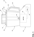
FIG. 1 is a schematic view of a food processor appliance according to one aspect of the present disclosure; -
FIG. 2 is a side perspective view of a dicer assembly in accordance with a first construction according to one aspect of the present disclosure; -
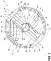
FIG. 3 is a plan view of a dicer assembly in accordance with a first construction according to one aspect of the present disclosure; -
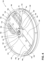
FIG. 4 is a top perspective view of a dicer assembly in accordance with a second construction according to one aspect of the present disclosure; -
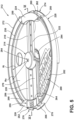
FIG. 5 is a top perspective view of a dicer assembly in accordance with a third construction according to one aspect of the present disclosure; and -
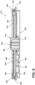
FIG. 6 is a side cross-sectional view of a dicer assembly in accordance with a third construction according to one aspect of the present disclosure. - The components in the figures are not necessarily to scale. Emphasis is instead being placed upon illustrating the principles described herein.
- The present illustrated embodiments reside primarily in combinations of method steps and apparatus components related to a food processor appliance with a dicing assembly. Accordingly, the apparatus components and method steps have been represented, where appropriate, by conventional symbols in the drawings, showing only those specific details that are pertinent to understanding the embodiments of the present disclosure so as not to obscure the disclosure with details that will be readily apparent to those of ordinary skill in the art having the benefit of the description herein. Further, like numerals in the description and drawings represent like elements.
- For purposes of description herein, the terms "upper," "lower," "right," "left," "rear," "front," "vertical," "horizontal," and derivatives thereof shall relate to the disclosure as oriented in
FIG. 1 . Unless stated otherwise, the term "front" shall refer to the surface of the element closer to an intended viewer, and the term "rear" shall refer to the surface of the element further from the intended viewer. However, it is to be understood that the disclosure may assume various alternative orientations, except where expressly specified to the contrary. It is also to be understood that the specific devices and processes illustrated in the attached drawings, and described in the following specification are simply exemplary embodiments of the inventive concepts defined in the appended claims. Hence, specific dimensions and other physical characteristics relating to the embodiments disclosed herein are not to be considered as limiting, unless the claims expressly state otherwise. - The terms "including," "comprises," "comprising," or any other variation thereof, are intended to cover a non-exclusive inclusion, such that a process, method, article, or apparatus that comprises a list of elements does not include only those elements but may include other elements not expressly listed or inherent to such process, method, article, or apparatus. An element preceded by "comprises a ... " does not, without more constraints, preclude the existence of additional identical elements in the process, method, article, or apparatus that comprises the element.
- Referring to
FIGS. 1-3 ,reference numeral 10 generally designates a food processor appliance with adicer assembly 12 in accordance with a first construction. Thedicer assembly 12 includes ablade unit 14 that has a drivenhub 16, afirst arm 18 that extends from the drivenhub 16, and asecond arm 20 that extends from the drivenhub 16 opposite thefirst arm 18. Afirst blade 22 is connected to and extends along thefirst arm 18. Afirst trolley 24 extends from thefirst arm 18 opposite the drivenhub 16, and asecond trolley 26 extends from thesecond arm 20 opposite the drivenhub 16. Anouter ring 28 defines aguide rail 30 slidably coupled with thefirst trolley 24 and thesecond trolley 26. - With reference now to
FIG. 1 , thefood processor appliance 10 may include abase 32, abowl assembly 33 that extends from thebase 32, and afeed chute assembly 34 that extends from thebowl assembly 33 opposite thebase 32. Thefeed chute assembly 34 may selectively couple to thebowl assembly 33, and thebowl assembly 33 may selectively couple to thebase 32. Thebowl assembly 33 may include ahandle 36, and thefeed chute assembly 34 may include anengagement member 38 configured to selectively lock and retain thefeed chute assembly 34 in place on thebowl assembly 33. Thefeed chute assembly 34 includes adicer assembly housing 40 for locating thedicer assembly 12. Thebase 32 may include amotor 42 and acontroller 44 operably connected to themotor 42. Themotor 42 is configured to rotatably power a drive mechanism oroutput drive shaft 46, which, in turn, rotatably drives thedicer assembly 12 via operable connection to the drivenhub 16. In operation, foodstuff is located in thefeed chute assembly 34 where it contacts thedicer assembly 12. Theblade unit 14, as driven by themotor 42, then rotates cutting the foodstuff and, thereafter, routes the cut foodstuff into thebowl assembly 33. - With reference now to
FIGS. 2-3 , theguide rail 30 is annularly shaped and defines an inner radius "Ri" and an outer radius "Ro" (FIG. 3 ). Theguide rail 30 includes at least one lip that at least partially defines at least one of the inner radius Ri or the outer radius Ro. For example, the at least one lip may include aninner lip 48 that defines the inner radius Ri and anouter lip 50 that defines the outer radius Ro. The at least one lip is in an overlapping alignment with thefirst trolley 24 and thesecond trolley 26. For example, an outwardly extendingflange 52 may be connected to one of thefirst trolley 24 and thesecond trolley 26 and theinner lip 48 is in overlapping radial alignment with the outwardly extendingflange 52. An inwardly extendingflange 54 may be connected to one of thefirst trolley 24 and thesecond trolley 26, and theouter lip 50 is in overlapping radial alignment with the inwardly extendingflange 54. As best illustrated inFIG. 2 , the outwardly extendingflange 52 extends from thefirst trolley 24 and the inwardly extendingflange 54 extends from thesecond trolley 26. The outwardly extendingflange 52 does not extend from thefirst trolley 24, and the inwardly extendingflange 54 does not extend from thesecond trolley 26. In this manner, the outwardly extendingflange 52 and the inwardly extendingflange 54 extend in the same direction because they are both located on diametricallyopposed trolleys blade unit 14 can be selectively inserted into theouter ring 28 via movement generally in the direction of the outwardly extendingflange 52 and the inwardly extendingflange 54. It should be appreciated that asecond blade 56 is connected to and extends along thesecond arm 20. Thefirst blade 22 and thesecond blade 56 may face opposite directions such that rotation of theblade unit 14 causes theblades - With continued reference to
FIGS. 2-3 , thefirst trolley 24 includes a first radialinner face 58 and a first radialouter face 60. The first radialinner face 58 and the first radialouter face 60 may be substantially radially shaped in close conformity with the inner radius Ri or the outer radius Ro, respectively. Afirst wedge face 62 extends between the first radialinner face 58 and the first radialouter face 60. More particularly, the first radialinner face 58 extends circumferentially and the first radialouter face 60 extends circumferentially a larger distance than the radiallyinner face 58 to define thefirst wedge face 62. Thefirst wedge face 62 may extend in a direction of thefirst blade 22 such that, during rotation of theblade unit 14, thefirst wedge face 62 rotationally travels in a direction of cutting. Similarly, thesecond trolley 26 includes a second radialinner face 64 and a second radialouter face 66. The second radialinner face 64 and the second radialouter face 66 may be substantially radially shaped in close conformity with the inner radius Ri or the outer radius Ro, respectively. Asecond wedge face 68 extends between the second radialinner face 64 and the second radialouter face 66. More particularly, the second radialinner face 64 extends circumferentially and the second radialouter face 66 extends circumferentially a larger distance than the radiallyinner face 64 to define thesecond wedge face 68. Thesecond wedge face 68 may extend in a direction of thesecond blade 56 such that, during rotation of theblade unit 14, thesecond wedge face 68 rotationally travels in a direction of cutting. - The
guide rail 30 may be located within anouter perimeter 70 of theouter ring 28. Asidewall 72 may extend along theouter perimeter 70 of theouter ring 28 and define afirst port 74 and asecond port 76 that are diametrically opposed. Thefirst port 74 and thesecond port 76 facilitate connection of theblade unit 14. Theouter ring 28 may further include afloor 78 that defines anopening 80, and a grill-shapedblade apparatus 82 is located in theopening 80. Thefeed chute assembly 34 may include a foodstuff passage in general alignment with the grill-shapedblade apparatus 82 such that, in use, foodstuff is pressed into cutting contact with the grill-shapedblade apparatus 82 as theblade unit 14 slices the foodstuff generally along a plane of rotation. The drivenhub 16 may include anaperture 84 with at least one connection structure 86 (FIG. 3 ) that extends into theaperture 84 to facilitate connection to a driving mechanism, such as themotor 42 and theoutput drive shaft 46. With reference back toFIG. 1 , thefeed chute assembly 34 may further define adicer assembly housing 40 that includes atop portion 90 and abottom portion 92 that sandwiches thedicer assembly 12 therein. Thefloor 78 may include apocket 94 that accommodates a bottom surface of the drivenhub 16, and thetop portion 90 of thedicer assembly housing 40 may contact a top surface of the drivenhub 16. Thetop portion 90 and thebottom portion 92 may be selectively connected to facilitate insertion of the dicer assembly 12 (e.g., at least the blade unit 14). Thefirst arm 18 may be angled upwardly towards thefirst blade 22, and thesecond arm 20 may be angled upwardly towards thesecond blade 56. In this manner, foodstuff cut by theblades opening 80 during rotation. - With reference now to
FIG. 4 , a dicer assembly 112 is illustrated in accordance with a second construction. The dicer assembly 112 may include all the same features, constructions, materials, and may be implemented in the samefood processor appliance 10 as the other constructions described herein. More particularly, the dicer assembly 112 includes ablade unit 114 that has a drivenhub 116, afirst arm 118 that extends from the drivenhub 116, and asecond arm 120 that extends from the drivenhub 116 opposite thefirst arm 118. Afirst blade 122 is connected to and extends along thefirst arm 118. Afirst trolley 124 extends from thefirst arm 118 opposite the drivenhub 116, and asecond trolley 126 extends from thesecond arm 120 opposite the drivenhub 116. Anouter ring 128 defines aguide rail 130 slidably coupled with thefirst trolley 124 and thesecond trolley 126. - With continued reference to
FIG. 4 , theguide rail 130 is annularly shaped and defines an inner radius "Ri" and an outer radius "Ro". Theguide rail 130 includes at least one lip that at least partially defines at least one of the inner radius Ri or the outer radius Ro. For example, the at least one lip may include aninner lip 148 that defines the inner radius Ri. The at least one lip is in an overlapping alignment with thefirst trolley 124 and thesecond trolley 126. Asecond blade 156 is connected to and extends along thesecond arm 120. Thefirst blade 122 and thesecond blade 156 may face opposite directions such that rotation of theblade unit 114 causes theblades blade unit 114 includes ahinge 150 that is configured to permit at least part of thefirst arm 118 to pivot with respect to at least part of thesecond arm 120 to facilitate connection of theblade unit 114 into theguide rail 130. For example, thehinge 150 may be located on the drivenhub 116. Thefirst arm 118 may include one ormore pivot shafts 154 pivotally connected to the drivenhub 116. - With continued reference to
FIG. 4 , thefirst trolley 124 includes a first radialinner face 158 that is substantially radially shaped and a first radialouter face 160 that is substantially radially shaped. The first radialouter face 160 may be located between the inner radius Ri or the outer radius Ro. Afirst wedge face 162 extends between the first radialinner face 158 and the first radialouter face 160. More particularly, the first radialinner face 158 extends circumferentially and the first radialouter face 160 extends circumferentially a larger distance than the radiallyinner face 158 to define thefirst wedge face 162. Thefirst wedge face 162 may extend in a direction of thefirst blade 122 such that, during rotation of theblade unit 114, thefirst wedge face 162 rotationally travels in a direction of cutting. Similarly, thesecond trolley 126 includes a second radialinner face 164 that is substantially radially shaped and a second radialouter face 166 that is substantially radially shaped. The second radialouter face 166 may be located between the inner radius Ri or the outer radius Ro. Asecond wedge face 168 extends between the second radialinner face 164 and the second radialouter face 166. More particularly, the second radialinner face 164 extends circumferentially and the second radialouter face 166 extends circumferentially a larger distance than the radiallyinner face 164 to define thesecond wedge face 168. Thesecond wedge face 168 may extend in a direction of thesecond blade 156 such that, during rotation of theblade unit 114, thesecond wedge face 168 rotationally travels in a direction of cutting. - The
guide rail 130 may be located on anouter perimeter 170 of theouter ring 128. Theouter ring 128 may include afloor 178 that defines anopening 180, and a grill-shapedblade apparatus 182 is located in theopening 180. Thefeed chute assembly 34 may include a foodstuff passage in general alignment with the grill-shapedblade apparatus 182 such that, in use, foodstuff is pressed into cutting contact with the grill-shapedblade apparatus 182 as theblade unit 114 slices the foodstuff generally along a plane of rotation. The drivenhub 116 may include anaperture 184 with at least oneconnection structure 186 that extends into theaperture 184 to facilitate connection to a driving mechanism, such as themotor 42 and theoutput drive shaft 46. When the dicer assembly 112 is integrated into afood processor appliance 10, such as that illustrated inFIG. 1 , thetop portion 90 and thebottom portion 92 of thedicer assembly housing 40 may sandwich the dicer assembly 112 therein. Thefloor 178 may include apocket 194 that accommodates a bottom surface of the drivenhub 116, and thetop portion 90 of thedicer assembly housing 40 may contact a top surface of the drivenhub 116. Thefirst arm 118 may be angled upwardly towards thefirst blade 122, and thesecond arm 120 may be angled upwardly towards thesecond blade 156. In this manner, foodstuff cut by theblades opening 180 during rotation. - With reference now to
FIGS. 5-6 , adicer assembly 212 is illustrated in accordance with a third construction. Thedicer assembly 212 may include all of the same features, constructions, materials, and may be implemented in the samefood processor appliance 10 as the other constructions described herein. More particularly, thedicer assembly 212 includes ablade unit 214 that has a driven hub 216 (FIG. 6 ), afirst arm 218 that extends from the drivenhub 216, and asecond arm 220 that extends from the drivenhub 216 opposite thefirst arm 218. Afirst blade 222 is connected to and extends along thefirst arm 218. Afirst trolley 224 extends from thefirst arm 218 opposite the drivenhub 216, and asecond trolley 226 extends from thesecond arm 220 opposite the drivenhub 216. Anouter ring 228 defines aguide rail 230 slidably coupled with thefirst trolley 224 and thesecond trolley 226. - With continued reference to
FIGS. 5-6 , theguide rail 230 is annularly shaped and defines an inner radius "Ri" and an outer radius "Ro" (FIG. 6 ). Theguide rail 230 includes at least one lip that at least partially defines at least one of the inner radius Ri or the outer radius Ro. For example, the at least one lip may include anouter lip 250 that defines the outer radius Ro. The at least one lip is in an overlapping alignment with thefirst trolley 224 and thesecond trolley 226. For example, an inwardly extending flange 254 (FIG. 6 ) may be connected to one of thefirst trolley 224 and thesecond trolley 226, and theouter lip 250 is in overlapping radial alignment with the inwardly extendingflange 254. Asecond blade 256 is connected to and extends along thesecond arm 220. Thefirst blade 222 and thesecond blade 256 may face opposite directions such that rotation of theblade unit 214 causes theblades blade unit 214 includes aclip 252 defining the inwardly extendingflange 254 that is selectably coupled to adepression 255 insecond trolley 256. More particularly, theclip 252 includes a disconnected position where the inwardly extendingflange 254 is radially spaced from theouter lip 250 and a connected position where theinwardly flange 254 is in overlapping radial alignment with theouter lip 250. Theclip 252 may include snap-fit features (not shown) configured to snap-fit into thesecond trolley 256. - With continued reference to
FIGS. 5-6 , thefirst trolley 224 includes a first radialinner face 258 that is substantially radially shaped and a first radialouter face 260 that is substantially radially shaped. The inwardly extendingflange 254 may extend (from a radially outward direction) at least partially between the inner radius Ri or the outer radius Ro. Afirst wedge face 262 extends between the first radialinner face 258 and the first radialouter face 260. More particularly, the first radialinner face 258 extends circumferentially and the first radialouter face 260 extends circumferentially a larger distance than the radiallyinner face 258 to define thefirst wedge face 262. Thefirst wedge face 262 may extend in a direction of thefirst blade 222 such that, during rotation of theblade unit 214, thefirst wedge face 262 rotationally travels in a direction of cutting. Similarly, thesecond trolley 226 includes a second radialinner face 264 that is substantially radially shaped and a second radialouter face 266 that is substantially radially shaped. The inwardly extendingflange 254 on theclip 252 may extend (from a radially outward direction) at least partially between the inner radius Ri or the outer radius Ro. Asecond wedge face 268 extends between the second radialinner face 264 and the second radialouter face 266. More particularly, the second radialinner face 264 extends circumferentially and the second radialouter face 266 extends circumferentially a larger distance than the radiallyinner face 264 to define thesecond wedge face 268. Thesecond wedge face 268 may extend in a direction of thesecond blade 256 such that, during rotation of theblade unit 214, thesecond wedge face 268 rotationally travels in a direction of cutting. - The
guide rail 230 may be located within anouter perimeter 270 of theouter ring 228. Asidewall 272 may extend along theouter perimeter 270 of theouter ring 228 and define afirst port 274 and asecond port 276 that are diametrically opposed. Thefirst port 274 and thesecond port 276 facilitate connection of theblade unit 214 to theouter ring 228. Theouter ring 228 may further include afloor 278 that defines anopening 280 and a grill-shapedblade apparatus 282 is located in theopening 280. Thefeed chute assembly 34 may include a foodstuff passage in general alignment with the grill-shapedblade apparatus 282 such that, in use, foodstuff is pressed into cutting contact with the grill-shapedblade apparatus 282 as theblade unit 214 slices the foodstuff generally along a plane of rotation. The drivenhub 216 may include anaperture 284 with at least one connection structure 286 (FIG. 6 ) extending into theaperture 284 to facilitate connection to a driving mechanism, such as themotor 42 and theoutput drive shaft 46. When thedicer assembly 212 is integrated into afood processor appliance 10, such as that illustrated inFIG. 1 , thetop portion 90 and thebottom portion 92 of thedicer assembly housing 40 may sandwich thedicer assembly 212 therein. Thefloor 278 may include apocket 294 that accommodates a bottom surface of the drivenhub 216 and thetop portion 90 of thedicer assembly housing 40 may contact a top surface of the drivenhub 216. Thetop portion 90 and thebottom portion 92 may be selectively connected to facilitate insertion of the dicer assembly 212 (e.g., at least the blade unit 214). Thefirst arm 218 may be angled upwardly towards thefirst blade 222 and thesecond arm 220 may be angled upwardly towards thesecond blade 256. In this manner, foodstuff cut by theblades opening 280 during rotation. - The invention disclosed herein is further summarized in the following paragraphs and is further characterized by combinations of any and all of the various aspects described therein.
- According to one aspect of the present disclosure, a dicer assembly for a food processor appliance includes a blade unit that has a driven hub, a first arm that extends from the driven hub, and a second arm that extends from the driven hub opposite the first arm. A first blade is connected to and extends along the first arm. A first trolley extends from the first arm opposite the driven hub, and a second trolley extends from the second arm opposite the driven hub. An outer ring defines a guide rail slidably coupled with the first trolley and the second trolley.
- According to another aspect, a guide rail defines at least one lip that is in an overlapping alignment with a first trolley and a second trolley.
- According to another aspect, a guide rail is annularly shaped and defines an inner radius and an outer radius, where at least one of the inner radius or the outer radius are defined by an at least one lip.
- According to another aspect, an outwardly extending flange is connected to one of a first trolley and a second trolley and at least one lip includes an inner lip defining an inner radius in overlapping radial alignment with the outwardly extending flange.
- According to another aspect, an inwardly extending flange is connected to one of a first trolley and a second trolley and at least one lip further includes an outer lip that defines an outer radius in overlapping radial alignment with the inwardly extending flange.
- According to another aspect, an outwardly extending flange extends from a first trolley and an inwardly extending flange extends from a second trolley.
- According to another aspect, an outwardly extending flange does not extend from a first trolley and an inwardly extending flange does not extend from a second trolley.
- According to another aspect, at least one lip includes an outer lip that defines an outer radius and an inwardly extending flange extends from a first trolley and is in overlapping radial alignment with the outer lip.
- According to another aspect, a second trolley includes a clip that further defines an inwardly extending flange that includes a disconnected position where the inwardly extending flange is radially spaced from an outer lip and a connected position where the inwardly extending flange is in overlapping radial alignment with the outer lip.
- According to another aspect, at least one lip includes an inner lip that defines an inner radius.
- According to another aspect, a blade unit includes a hinge configured to permit at least part of a first arm to pivot with respect to at least part of a second arm to facilitate connection of a blade unit.
- According to another aspect, an outer ring defines a sidewall located radially outwardly from a guide rail and a sidewall defines a pair of opposing ports to facilitate connection of a blade unit.
- According to yet another aspect of the present disclosure, a dicer assembly for a food processor appliance includes a blade unit that has a driven hub, a first arm that extends from the driven hub, and a second arm that extends from the driven hub opposite the first arm. A first blade is connected to and extends along the first arm, and a second blade is connected to and extends along the second arm. A first trolley extends from the first arm opposite the driven hub, and a second trolley extends from the second arm opposite the driven hub. An outer ring defines a floor, and a guide rail extends annularly from the floor that is slideably coupled with the first trolley and the second trolley.
- According to another aspect, a floor defines an opening and a grill-shaped blade apparatus is located in the opening.
- According to another aspect, a driven hub includes an aperture with at least one connection structure extending into the aperture to facilitate connection to a driving mechanism and rotation of a blade unit.
- According to another aspect, a guide rail defines an inner lip defining an inner radius of a guide rail.
- According to another aspect, a hinge pivotally connects a first arm to a driven hub.
- According to another aspect, a guide rail defines at least one of an inner lip or an outer lip and at least one of an outwardly extending flange or an inwardly extending flange extends from both a first trolley and a second trolley.
- According to yet another aspect of the present disclosure, a dicer assembly for a food processor appliance includes an outer ring that defines a guide rail with an outer lip that defines an outer radius of the guide rail. A blade unit includes a driven hub, a first arm that extends from the driven hub, and a second arm that extends from the driven hub opposite the first arm. A first blade is connected to and extends along the first arm and a second blade is connected to and extends along the second arm. A first trolley extends from the first arm opposite the driven hub and includes an inwardly extending flange that is slidably coupled and in overlapping radial alignment with the outer lip. A second trolley extends from the second arm opposite the driven hub and is slidably coupled to the guide rail.
- According to another aspect, a guide rail includes an inner lip that defines an inner radius of a guide rail and a second arm includes an outwardly extending flange slidably coupled and in overlapping radial alignment with the inner lip.
- It will be understood by one having ordinary skill in the art that construction of the described disclosure and other components is not limited to any specific material. Other exemplary embodiments of the disclosure disclosed herein may be formed from a wide variety of materials, unless described otherwise herein.
- For purposes of this disclosure, the term "coupled" (in all of its forms, couple, coupling, coupled, etc.) generally means the joining of two components (electrical or mechanical) directly or indirectly to one another. Such joining may be stationary in nature or movable in nature. Such joining may be achieved with the two components (electrical or mechanical) and any additional intermediate members being integrally formed as a single unitary body with one another or with the two components. Such joining may be permanent in nature or may be removable or releasable in nature unless otherwise stated.
Claims (15)
- A dicer assembly (12, 112, 212) for a food processor appliance (10) comprising:a blade unit (14, 114, 214) including a driven hub (16, 116, 216), a first arm (18, 118, 218) extending from the driven hub (16, 116, 216), and a second arm (20, 120, 220) extending from the driven hub (16, 116, 216) opposite the first arm (18, 118, 218);a first blade connected to and extending along the first arm (18, 118, 218);a first trolley (24, 124, 224) extending from the first arm (18, 118, 218) opposite the driven hub (16, 116, 216);a second trolley (26, 126, 226) extending from the second arm (20, 120, 220) opposite the driven hub (16, 116, 216); andan outer ring (28, 128, 228) defining a guide rail (30, 130, 230) slidably coupled with the first trolley (24, 124, 224) and the second trolley (26, 126, 226).
- The dicer assembly (12, 112, 212) of claim 1, wherein the guide rail (30, 130, 230) defines at least one lip (48, 50, 148, 250) that is in an overlapping alignment with the first trolley (24, 124, 224) and the second trolley (26, 126, 226).
- The dicer assembly (12, 112, 212) of claim 2, wherein the guide rail (30, 130, 230) is annularly shaped and defines an inner radius (Ri) and an outer radius (Ro), where at least one of the inner radius (Ri) or the outer radius (Ro) are defined by the at least one lip (48, 50, 148, 250).
- The dicer assembly (12) of claim 3, wherein an outwardly extending flange (52) is connected to one of the first trolley (24) and the second trolley (26) and the at least one lip (48, 50) includes an inner lip (48) defining the inner radius (Ri) in overlapping radial alignment with the outwardly extending flange (52).
- The dicer assembly (12) of claim 4, wherein an inwardly extending flange (54) is connected to one of the first trolley (24) and the second trolley (26) and the at least one lip (50) further includes an outer lip (50) defining the outer radius (Ro) in overlapping radial alignment with an inwardly extending flange (54).
- The dicer assembly (12) of claim 5, wherein the outwardly extending flange (52) extends from the first trolley (24) and the inwardly extending flange (54) extends from the second trolley (26).
- The dicer assembly (12) of claim 6, wherein the outwardly extending flange (52) does not extend from the second trolley (26) and the inwardly extending flange (54) does not extend from the first trolley (24).
- The dicer assembly (12, 212) of claim 3, wherein the at least one lip (50, 250) includes an outer lip (50, 250) defining the outer radius (Ro) and an inwardly extending flange (54, 254) extends from the first trolley (24, 224) and is in overlapping radial alignment with the outer lip (50, 250).
- The dicer assembly (212) of claim 8, wherein the second trolley (226) includes a clip (252) further defining the inwardly extending flange (254) that includes a disconnected position where the inwardly extending flange (254) is radially spaced from the outer lip (250) and a connected position where the inwardly extending flange (254) is in overlapping radial alignment with the outer lip (250).
- The dicer assembly (12, 112, 212) of claim 3, wherein the at least one lip (48, 50, 148, 250) includes an inner lip (48, 50, 148, 250) defining the inner radius (Ri).
- The dicer assembly (112) as in one of claims 1-3 and 10, wherein the blade unit (114) includes a hinge (150) configured to permit at least part of the first arm (118) to pivot with respect to at least part of the second arm (120) to facilitate connection of the blade unit (114).
- The dicer assembly (12, 212) as in one of claims 1-3, wherein the outer ring (28, 228) defines a sidewall (72, 272) located radially outwardly from the guide rail (30, 230) and the sidewall (72, 272) defines a pair of opposing ports (74, 76, 274, 276) to facilitate connection of the blade unit (14, 214).
- The dicer assembly (12, 112, 212) as in one of claims 1-10, wherein the outer ring (28, 128, 228) defines a floor (78, 178, 278), and the floor (78, 178, 278) defines an opening (80, 180, 280) and a blade apparatus (82, 182, 282) is located in the opening (80, 180, 280).
- The dicer assembly (12, 112, 212) of claim 13, wherein the blade apparatus (82, 182, 282) is grill-shaped.
- The dicer assembly (12, 112, 212) as in one of claims 1-10, wherein the driven hub (16, 116, 216) includes an aperture (84, 184, 284) with at least one connection structure (86, 186, 286) extending into the aperture (84, 184, 284) to facilitate connection to a driving mechanism and rotation of the blade unit (14, 114, 214).
Applications Claiming Priority (1)
| Application Number | Priority Date | Filing Date | Title |
|---|---|---|---|
| US18/153,619 US20240239000A1 (en) | 2023-01-12 | 2023-01-12 | Food processor optimized dicing kit system |
Publications (2)
| Publication Number | Publication Date |
|---|---|
| EP4400011A1 true EP4400011A1 (en) | 2024-07-17 |
| EP4400011B1 EP4400011B1 (en) | 2026-03-04 |
Family
ID=89573748
Family Applications (1)
| Application Number | Title | Priority Date | Filing Date |
|---|---|---|---|
| EP24151292.0A Active EP4400011B1 (en) | 2023-01-12 | 2024-01-11 | Food processor optimized dicing kit system |
Country Status (4)
| Country | Link |
|---|---|
| US (1) | US20240239000A1 (en) |
| EP (1) | EP4400011B1 (en) |
| CN (1) | CN118319177A (en) |
| AU (1) | AU2024200163A1 (en) |
Citations (3)
| Publication number | Priority date | Publication date | Assignee | Title |
|---|---|---|---|---|
| US9763543B2 (en) * | 2013-11-28 | 2017-09-19 | Elec-Tech International Co., Ltd. | Food processor with a dicing function |
| CN107756510A (en) * | 2016-08-15 | 2018-03-06 | 广东德豪润达电气股份有限公司 | Dregs removing device and the food processor with function of dicing |
| WO2021259251A1 (en) * | 2020-06-23 | 2021-12-30 | Whirlpool Corporation | Storage caddy for a food processor assembly |
Family Cites Families (5)
| Publication number | Priority date | Publication date | Assignee | Title |
|---|---|---|---|---|
| AU2012276060B2 (en) * | 2011-06-27 | 2016-10-27 | Atlas Pacific Engineering Company | Slice blade assembly with non-welded replaceable blades |
| EP2767202A1 (en) * | 2013-02-14 | 2014-08-20 | Browne & Co | Flexible food processor blade |
| SI24799A (en) * | 2014-09-04 | 2016-03-31 | Bsh Bosch Und Siemens Haushaltsgeraete Gmbh | Lock of cube cutter for kitchen appliance |
| WO2016181815A1 (en) * | 2015-05-09 | 2016-11-17 | デルタ工業株式会社 | Seat slide adjuster |
| CN108908452A (en) * | 2018-07-04 | 2018-11-30 | 芜湖喜源味食品有限公司 | A kind of cookies raw material cutoff device that notch is smooth |
-
2023
- 2023-01-12 US US18/153,619 patent/US20240239000A1/en active Pending
-
2024
- 2024-01-11 EP EP24151292.0A patent/EP4400011B1/en active Active
- 2024-01-11 AU AU2024200163A patent/AU2024200163A1/en active Pending
- 2024-01-12 CN CN202410046675.3A patent/CN118319177A/en active Pending
Patent Citations (3)
| Publication number | Priority date | Publication date | Assignee | Title |
|---|---|---|---|---|
| US9763543B2 (en) * | 2013-11-28 | 2017-09-19 | Elec-Tech International Co., Ltd. | Food processor with a dicing function |
| CN107756510A (en) * | 2016-08-15 | 2018-03-06 | 广东德豪润达电气股份有限公司 | Dregs removing device and the food processor with function of dicing |
| WO2021259251A1 (en) * | 2020-06-23 | 2021-12-30 | Whirlpool Corporation | Storage caddy for a food processor assembly |
Also Published As
| Publication number | Publication date |
|---|---|
| CN118319177A (en) | 2024-07-12 |
| US20240239000A1 (en) | 2024-07-18 |
| AU2024200163A1 (en) | 2024-08-01 |
| EP4400011B1 (en) | 2026-03-04 |
Similar Documents
| Publication | Publication Date | Title |
|---|---|---|
| AU2014200438B2 (en) | Food processor mixer attachment | |
| US4884755A (en) | Food processor | |
| EP2677904B1 (en) | A food processing device with an externally operated adjustment mechanism | |
| EP1702545A1 (en) | Drive coupler for a food preparation device | |
| EP2382903B1 (en) | Lockable adjustable blade assembly for food processor | |
| CN110799076A (en) | Mixer with safety mechanism | |
| EP2564745A1 (en) | A lid for a food processor | |
| EP2724650B1 (en) | Dicing tool for domestic food processing device | |
| CN104159484A (en) | Food processor or chopper | |
| EP4248812A2 (en) | Cordless food processor | |
| US20230414041A1 (en) | Storage caddy for a food processor assembly | |
| EP3316750B1 (en) | Food processing apparatus | |
| EP4400011B1 (en) | Food processor optimized dicing kit system | |
| JP6541245B2 (en) | Safety bearing mechanism and food processing device | |
| WO2024177763A1 (en) | Food blender and scraper assembly for a food blender | |
| US6955117B2 (en) | Tool for a food processing machine, in particular of the mixer type, and a machine provided with a tool of this type | |
| US20250066177A1 (en) | Lateral-cutting can opener with integrated lid removal feature and method for using same | |
| WO2007103171A2 (en) | Reciprocating blade food and circumferentially driven blade food preparation appliance | |
| US20230028801A1 (en) | Cutting device for a kitchen utensil | |
| KR200500290Y1 (en) | Blender | |
| KR20170035759A (en) | Food processing machine comprising a structure for transferring a rotating force | |
| EP3192416B1 (en) | Rotary cooking device | |
| US20240285128A1 (en) | Cover and motor mount for food blender sound enclosure | |
| WO2024177770A1 (en) | Food blender and scraper assembly for a food blender | |
| KR20180119855A (en) | Food processing machine comprising a structure for transferring a rotating force |
Legal Events
| Date | Code | Title | Description |
|---|---|---|---|
| PUAI | Public reference made under article 153(3) epc to a published international application that has entered the european phase |
Free format text: ORIGINAL CODE: 0009012 |
|
| STAA | Information on the status of an ep patent application or granted ep patent |
Free format text: STATUS: THE APPLICATION HAS BEEN PUBLISHED |
|
| AK | Designated contracting states |
Kind code of ref document: A1 Designated state(s): AL AT BE BG CH CY CZ DE DK EE ES FI FR GB GR HR HU IE IS IT LI LT LU LV MC ME MK MT NL NO PL PT RO RS SE SI SK SM TR |
|
| STAA | Information on the status of an ep patent application or granted ep patent |
Free format text: STATUS: REQUEST FOR EXAMINATION WAS MADE |
|
| 17P | Request for examination filed |
Effective date: 20250117 |
|
| STAA | Information on the status of an ep patent application or granted ep patent |
Free format text: STATUS: EXAMINATION IS IN PROGRESS |
|
| 17Q | First examination report despatched |
Effective date: 20250313 |
|
| GRAP | Despatch of communication of intention to grant a patent |
Free format text: ORIGINAL CODE: EPIDOSNIGR1 |
|
| STAA | Information on the status of an ep patent application or granted ep patent |
Free format text: STATUS: GRANT OF PATENT IS INTENDED |
|
| INTG | Intention to grant announced |
Effective date: 20250829 |
|
| GRAS | Grant fee paid |
Free format text: ORIGINAL CODE: EPIDOSNIGR3 |
|
| GRAA | (expected) grant |
Free format text: ORIGINAL CODE: 0009210 |
|
| STAA | Information on the status of an ep patent application or granted ep patent |
Free format text: STATUS: THE PATENT HAS BEEN GRANTED |
|
| AK | Designated contracting states |
Kind code of ref document: B1 Designated state(s): AL AT BE BG CH CY CZ DE DK EE ES FI FR GB GR HR HU IE IS IT LI LT LU LV MC ME MK MT NL NO PL PT RO RS SE SI SK SM TR |
|
| REG | Reference to a national code |
Ref country code: CH Ref legal event code: F10 Free format text: ST27 STATUS EVENT CODE: U-0-0-F10-F00 (AS PROVIDED BY THE NATIONAL OFFICE) Effective date: 20260304 Ref country code: GB Ref legal event code: FG4D |
|
| REG | Reference to a national code |
Ref country code: IE Ref legal event code: FG4D |
|
| REG | Reference to a national code |
Ref country code: DE Ref legal event code: R096 Ref document number: 602024002861 Country of ref document: DE |
|
| P01 | Opt-out of the competence of the unified patent court (upc) registered |
Free format text: CASE NUMBER: UPC_APP_0008390_4400011/2026 Effective date: 20260302 |