EP4399472B1 - Mécanisme de mise à feu avec interface secondaire pour une arme à feu - Google Patents
Mécanisme de mise à feu avec interface secondaire pour une arme à feu Download PDFInfo
- Publication number
- EP4399472B1 EP4399472B1 EP22785788.5A EP22785788A EP4399472B1 EP 4399472 B1 EP4399472 B1 EP 4399472B1 EP 22785788 A EP22785788 A EP 22785788A EP 4399472 B1 EP4399472 B1 EP 4399472B1
- Authority
- EP
- European Patent Office
- Prior art keywords
- sear
- hammer
- actuator
- hook
- axis
- Prior art date
- Legal status (The legal status is an assumption and is not a legal conclusion. Google has not performed a legal analysis and makes no representation as to the accuracy of the status listed.)
- Active
Links
Images


Classifications
-
- F—MECHANICAL ENGINEERING; LIGHTING; HEATING; WEAPONS; BLASTING
- F41—WEAPONS
- F41A—FUNCTIONAL FEATURES OR DETAILS COMMON TO BOTH SMALLARMS AND ORDNANCE, e.g. CANNONS; MOUNTINGS FOR SMALLARMS OR ORDNANCE
- F41A17/00—Safety arrangements, e.g. safeties
- F41A17/74—Hammer safeties, i.e. means for preventing the hammer from hitting the cartridge or the firing pin
-
- F—MECHANICAL ENGINEERING; LIGHTING; HEATING; WEAPONS; BLASTING
- F41—WEAPONS
- F41A—FUNCTIONAL FEATURES OR DETAILS COMMON TO BOTH SMALLARMS AND ORDNANCE, e.g. CANNONS; MOUNTINGS FOR SMALLARMS OR ORDNANCE
- F41A19/00—Firing or trigger mechanisms; Cocking mechanisms
- F41A19/06—Mechanical firing mechanisms, e.g. counterrecoil firing, recoil actuated firing mechanisms
- F41A19/14—Hammers, i.e. pivotably-mounted striker elements; Hammer mountings
-
- F—MECHANICAL ENGINEERING; LIGHTING; HEATING; WEAPONS; BLASTING
- F41—WEAPONS
- F41A—FUNCTIONAL FEATURES OR DETAILS COMMON TO BOTH SMALLARMS AND ORDNANCE, e.g. CANNONS; MOUNTINGS FOR SMALLARMS OR ORDNANCE
- F41A17/00—Safety arrangements, e.g. safeties
- F41A17/74—Hammer safeties, i.e. means for preventing the hammer from hitting the cartridge or the firing pin
- F41A17/82—Hammer safeties, i.e. means for preventing the hammer from hitting the cartridge or the firing pin trigger-operated, i.e. the movement of the trigger bringing a hammer safety into inoperative position during firing
-
- F—MECHANICAL ENGINEERING; LIGHTING; HEATING; WEAPONS; BLASTING
- F41—WEAPONS
- F41A—FUNCTIONAL FEATURES OR DETAILS COMMON TO BOTH SMALLARMS AND ORDNANCE, e.g. CANNONS; MOUNTINGS FOR SMALLARMS OR ORDNANCE
- F41A19/00—Firing or trigger mechanisms; Cocking mechanisms
- F41A19/06—Mechanical firing mechanisms, e.g. counterrecoil firing, recoil actuated firing mechanisms
- F41A19/10—Triggers; Trigger mountings
-
- F—MECHANICAL ENGINEERING; LIGHTING; HEATING; WEAPONS; BLASTING
- F41—WEAPONS
- F41A—FUNCTIONAL FEATURES OR DETAILS COMMON TO BOTH SMALLARMS AND ORDNANCE, e.g. CANNONS; MOUNTINGS FOR SMALLARMS OR ORDNANCE
- F41A19/00—Firing or trigger mechanisms; Cocking mechanisms
- F41A19/06—Mechanical firing mechanisms, e.g. counterrecoil firing, recoil actuated firing mechanisms
- F41A19/12—Sears; Sear mountings
Definitions
- the present disclosure relates to firearms and, more particularly, to a firing mechanism for a firearm.
- the retention/arming of a hammer in a traditional hammer-fired firing mechanism for a firearm is done by a surface on the hammer that interacts with a corresponding surface on a sear.
- This interface is typically protected from unintentional disconnection by using a balanced sear, a spring to bias the sear's position in relation to the hammer, and/or an interface geometry that produces a positive engagement between the hammer and sear surfaces.
- the invention is a firing mechanism according to claims 1 or 5, and their dependent claims.
- Embodiments of the present disclosure address the above problems and more by providing a secondary interface between the hammer and sear of a firearm that will automatically be engaged in case the primary interface fails.
- the secondary safety interface is part of the hammer and sear and does not require any additional components.
- the secondary safety interface in the event of a primary interface failure, will engage without any further action and will hold the hammer in its "armed" position. Further, embodiments of the secondary interface, when activated, disconnect the hammer and the sear from the trigger, creating a locked-out condition. Manually cycling the slide or operating group of the weapon will not allow the secondary interface to be separated and the secondary interface will re-engage every time until the weapon is disassembled for repair.
- the locked-out mechanism allows for a safe disassembly of the weapon. As such, the presently disclosed firing mechanism with secondary interface provides significant safety against unintentional discharge of the firearm in case of part failures.
- references to "a”, “an” or other indefinite article in the present disclosure encompasses one or more than one of the described element.
- reference to a spring encompasses one or more springs
- reference to a round encompasses one or more rounds, and so forth.
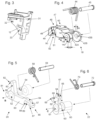
- a firing mechanism 10 includes a trigger group frame or housing 12, a trigger 15, a trigger bar 16, a hammer 18, a sear 20 and an actuator 22. It will be appreciated that embodiments of the firing mechanism 10 can involve a subset of these elements, such as the hammer 18, sear 20 and actuator 22, for example.
- the hammer 18 is formed with a body 40 and opposed legs 42A and 42B, each of which includes a respective opening 43A, 43B for receiving a hammer spring 44 and a hammer pin 45.
- Leg 42B can be formed as a rim of constant thickness or depth D1 that forms the opening 43B, whereas leg 42A can be formed as a rim having a wider depth D2 for approximately three quarters of the rim and a narrower depth (not shown) for approximately one quarter of the rim.
- Leg 42A is thus formed with an internal wall 144 on the narrower depth portion extending between a leading edge 141 and a trailing edge 142 of the wider depth portion D2.
- a hammer head segment 46 is formed with the body 40 and extends away from the opposed legs 42A and 42B.
- the hammer head segment 46 includes a striking face 47 which impacts a firing pin (not shown) during operation of the firearm.
- the hammer head segment 46 is further formed with a rampart wall 48 extending downwardly from the striking face 47 and a latching edge 49 extending laterally inwardly toward the legs 42A and 42B from the rampart wall 48.
- a sear facing wall 90 extends from the latching edge 49 and lies opposite a hammer slot wall 91, wherein the sear facing wall 90 and the hammer slot wall 91 form an opening 92 for receiving a sear extension arm 80 of the sear 20 during operation.
- the sear 20 is formed with a body 50 having a bored opening 52 and an extension base 54 formed with a foot 55 having an opening 56 opposed to opening 52, wherein a sear spring 58 can be positioned between the body 50 and extension base 54 and a sear pin 59 can be inserted through the openings 52, 56 and the sear spring 58.
- the sear 20 is formed with an extension arm 80 extending substantially perpendicularly above the bored opening 52 and proximate a first end 81 of the body 50.
- the extension arm 80 is formed with a first hook 82 having a top jaw surface 83, which slidingly engages the latching edge 49 of the hammer 18 during operation of the firing mechanism as described elsewhere herein.
- the sear 20 is further formed with a second hook 84 proximate a second end 85 of the body 50, wherein the second hook 84 can be provided with a generally C-shaped cross-section and an actuator-engaging head 87.
- the inner surface 88 of the second hook 84 forms a slot 89 wherein portions of an actuator arm 62 of the actuator 22 may reside during different operations of the firing mechanism of the present disclosure.
- the outer surface 57 of the second hook 84 can engage trailing edge 142 of the inner portion of the hammer 18 during operation, as described elsewhere herein. This engagement between outer surface 57 of the second hook 84 and the trailing edge 142 of the hammer 18 provides a secondary interface 99 in accordance with embodiments of the present disclosure.
- the actuator 22 is formed with an actuator base 60 and an actuator arm 62 extending radially outwardly of the actuator base 60, wherein the actuator base 60 includes an actuator bore 61 extending axially therethrough.
- the actuator base 60 can be formed with a spring slot 63 and the actuator arm 62 can be formed with a pair of opposed prongs 64, 65 forming a notch 67 therebetween.
- the actuator arm 62 can further be formed with an extension rod 68 extending substantially perpendicularly therefrom, and an actuator interface 69 extends radially outwardly from the extension rod 68.
- the spring slot 63 is sized to receive an actuator spring 70, and an actuator pin 72 extends through the actuator bore 61 and through the actuator spring 70.
- the actuator interface 69 extends from the actuator arm 62 for manually blocking the actuator 22 from separating from the sear 20. This is illustrated in Fig. 11 , where a safety lever 150 engages actuator interface 69 at edge 152. As the safety lever 150 is secured about and engaged with sear pin 59, any restriction on the rotation of the safety lever 150 will restrict the rotation of the sear 20.
- the frame or housing 12 is provided with opposing hammer pin openings 3 1, sear pin openings 32 and actuator pin openings 33 for receiving the hammer pin 45, sear pin 59 and actuator pin 72, respectively.
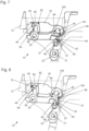
- This enables the hammer 18 to be pivotably mounted about a hammer pin axis A, sear 20 to be pivotably mounted about a sear pin axis B and actuator base 60 to be pivotably mounted about an actuator axis C.
- the hammer spring 44 biases the hammer 18 against the frame or housing 12 so that the hammer 18 is inclined to rotate clockwise with sufficient force to carry out its duty to forcibly strike a firing pin when the trigger 15 is pulled.
- the sear spring 58 biases the sear 20 against the frame or housing 12 so that the sear 20 is inclined to rotate counterclockwise.
- a primary interface 75 is operably formed between the top jaw surface 83 of the first hook 82 of the sear 20 and the latching edge 49 of the hammer head segment 46 of the hammer 18.
- the sear spring 58 biases the first hook 82 into the primary interface 75 and biases the second hook 84 towards the hammer 18.
- the hammer spring 44 biases the hammer 18 into the primary interface 75 and is operable to overcome the biasing of the sear spring 58.
- the trigger bar 16 pushes the extension rod 68 of the actuator 22, causing the actuator to rotate about axis C against its bias in a counterclockwise direction.
- Such rotation causes the actuator-engaging head 87 of the second hook to slide past prong 65 and then the spring force of the hammer spring 44 overcomes the resistance from the sear spring 58 such that the top jaw surface 83 of the first hook 82 of the sear 20 slides down the latching edge 49 and thereby releases the hammer 18 so that the hammer 18 can strike the firing pin.
- the trigger 15 is thus operable to rotate the actuator 22 about the actuator axis C (represented by actuator pin 72 location in Figs.
- the slide (not shown) is racked to reset the hammer, whereupon the slide engages the hammer body 40 and overcomes the biasing force of the hammer spring 44 to re-engage the top jaw surface 83 of the first hook 82 of the sear with the latching edge 49 of the hammer head segment 46 of the hammer 18.
- the second hook 84 is lifted away from the actuator prongs 64, 65, allowing the actuator 22 to rotate clockwise about its axis so that the prongs 64, 65 align around the actuator-engaging head 87.
- the primary interface 75 and the secondary interface 99 are at different distances from the sear axis B. As shown in Figs. 7 through 10 , the secondary interface 99 is farther than the primary interface 75 from the sear axis B (represented by sear pin 59 location) to ensure it will disengage first and will not inhibit the normal operation of the firing mechanism. Further, the alignment of the interfaces 75, 99 on the hammer are opposite. As shown in Figs. 7 through 10 , the primary interface 75 is farther away from the hammer axis A (represented by hammer pin 45 location) than the secondary interface 99 to allow the hammer spring 44 to create a larger force on the sear 20 and force the disconnect once the actuator 22 is moved out of the way.
Landscapes
- Engineering & Computer Science (AREA)
- General Engineering & Computer Science (AREA)
- Toys (AREA)
- Percussive Tools And Related Accessories (AREA)
Claims (10)
- Mécanisme de mise à feu (10) comprenant :un chien (18) monté de manière pivotante autour d'un axe de chien (45) ;une gâchette (20) montée de manière pivotante autour d'un axe de gâchette (59), dans lequel la gâchette (20) comprend un premier crochet (82) pouvant être actionné pour fournir une interface principale (75) avec le chien (18) ;un actionneur (22) comprenant une base d'actionneur (60) et un bras d'actionneur (62) s'étendant radialement vers l'extérieur à partir de la base d'actionneur (60), dans lequel la base d'actionneur (60) est montée, de manière pivotante, autour d'un axe d'actionneur (72) ; etdans lequel la gâchette (20) comprend en outre un second crochet (84) pouvant être actionné pour fournir une interface secondaire (99) avec le chien (18) et dans lequel, suite à la défaillance du premier crochet (82), le second crochet (84) fixe le chien (18) et empêche le tir de l'arme à feu,caractérisé en ce que :
le bras d'actionneur (62) comprend une encoche (67) et comprenant en outre une détente (15) pouvant être actionnée pour faire tourner l'actionneur (22) autour de l'axe d'actionneur (72) afin de dégager le second crochet (84) de la gâchette (20) de l'encoche (67) du bras d'actionneur (62), permettant ainsi au premier crochet (82) de la gâchette (20) de libérer le chien (18) et permettre à l'arme à feu de tirer. - Mécanisme de mise à feu (10) selon la revendication 1, dans lequel l'interface principale (75) est une première distance par rapport à l'axe de gâchette (59) et l'interface secondaire (99) est une seconde distance par rapport à l'axe de gâchette (59) et en outre dans lequel la première distance est inférieure à la seconde distance.
- Mécanisme de mise à feu (10) selon la revendication 1, dans lequel le bras d'actionneur (62) comprend une première dent (64) et une seconde dent (65) définissant l'encoche (67).
- Mécanisme de mise à feu (10) selon la revendication 1, dans lequel le chien (18) comprend une patte formée avec une partie de profondeur plus large et une partie de profondeur plus étroite, dans lequel une paroi interne sur la partie de profondeur plus étroite s'étend entre un bord d'attaque (141) et un bord de fuite (142) de la partie de profondeur plus large, dans lequel le second crochet (84) comprend une surface externe, et dans lequel la surface externe du second crochet et le bord de fuite (142) de la partie de profondeur plus large de la gâchette (20) peuvent être actionnés pour fournir l'interface secondaire (99).
- Mécanisme de mise à feu (10) comprenant :une carcasse ou boîtier (12) ;un chien (18) fixé à l'intérieur de la carcasse ou du boîtier (12) et monté, de manière pivotante, autour d'un axe de chien (45) ;une gâchette (20) fixée à l'intérieur de la carcasse ou du boîtier (12) et montée, de manière pivotante, autour d'un axe de gâchette (59), dans lequel la gâchette (20) comprend un premier crochet (82) pouvant être actionné pour fournir une interface principale (75) avec le chien (18) et un second crochet (84) pouvant être actionné pour fournir une interface secondaire (99) avec le chien (18) ;dans lequel :un actionneur (22) fixé à l'intérieur de la carcasse ou du boîtier (12) et monté, de manière pivotante, autour d'un axe d'actionneur (72), dans lequel l'actionneur (22) comprend une encoche (67) pouvant être actionnée pour mettre en prise le second crochet (84) de la gâchette (20) ; etune détente (15) pouvant être actionnée pour faire tourner l'actionneur (22) autour de l'axe d'actionneur (72) afin de dégager le second crochet (84) de la gâchette (20) de l'actionneur (22), permettant ainsi au premier crochet (82) de la gâchette (20) de libérer le chien (18) et de permettre à l'arme à feu de tirer;dans lequel, suite à la défaillance du premier crochet (82), le second crochet (84) fixe le chien (18) et empêche le tir de l'arme à feu.
- Mécanisme de mise à feu (10) selon l'une quelconque des revendications 1 à 5, dans lequel la défaillance du premier crochet (82) rend la détente (15) non opérationnelle pour le tir de l'arme à feu.
- Mécanisme de mise à feu (10) selon la revendication 5, dans lequel l'interface principale (75) est une première distance par rapport à l'axe de gâchette (59) et l'interface secondaire (99) est une seconde distance par rapport à l'axe de gâchette (59), et en outre dans lequel la première distance est inférieure à la seconde distance.
- Mécanisme de mise à feu (10) selon l'une quelconque des revendications 1 et 5, comprenant en outre un ressort de gâchette (58) sollicitant le premier crochet (82) dans l'interface principale (75) et sollicitant le second crochet (84) vers le chien (18).
- Mécanisme de mise à feu (10) selon l'une quelconque des revendications 1 à 5, comprenant en outre un ressort de chien (44) sollicitant le chien (18) dans l'interface principale (75) et pouvant être actionné pour venir à bout de la sollicitation du ressort de gâchette (58).
- Mécanisme de mise à feu (10) selon la revendication 5, dans lequel l'actionneur (22) comprend une base d'actionneur (60) et un bras d'actionneur (62) s'étendant radialement vers l'extérieur à partir de la base d'actionneur (60), dans lequel une interface s'étend à partir du bras d'actionneur (62) pour empêcher manuellement l'actionneur (22) de se séparer de la gâchette (20).
Applications Claiming Priority (2)
| Application Number | Priority Date | Filing Date | Title |
|---|---|---|---|
| US17/471,930 US11927409B2 (en) | 2021-09-10 | 2021-09-10 | Firing mechanism with secondary interface for a firearm |
| PCT/IB2022/058581 WO2023037336A1 (fr) | 2021-09-10 | 2022-09-12 | Mécanisme de mise à feu avec interface secondaire pour une arme à feu |
Publications (3)
| Publication Number | Publication Date |
|---|---|
| EP4399472A1 EP4399472A1 (fr) | 2024-07-17 |
| EP4399472B1 true EP4399472B1 (fr) | 2025-03-05 |
| EP4399472C0 EP4399472C0 (fr) | 2025-03-05 |
Family
ID=83593880
Family Applications (1)
| Application Number | Title | Priority Date | Filing Date |
|---|---|---|---|
| EP22785788.5A Active EP4399472B1 (fr) | 2021-09-10 | 2022-09-12 | Mécanisme de mise à feu avec interface secondaire pour une arme à feu |
Country Status (3)
| Country | Link |
|---|---|
| US (1) | US11927409B2 (fr) |
| EP (1) | EP4399472B1 (fr) |
| WO (1) | WO2023037336A1 (fr) |
Cited By (1)
| Publication number | Priority date | Publication date | Assignee | Title |
|---|---|---|---|---|
| RU240604U1 (ru) * | 2025-08-25 | 2026-01-20 | Акционерное Общество "Ижевский Механический Завод" | Огнестрельное оружие |
Family Cites Families (24)
| Publication number | Priority date | Publication date | Assignee | Title |
|---|---|---|---|---|
| US2366823A (en) | 1943-01-29 | 1945-01-09 | Western Cartridge Co | Firing mechanism for firearms |
| US2690095A (en) * | 1949-02-11 | 1954-09-28 | Us Sec War | Automatic sear |
| US3402498A (en) * | 1966-10-25 | 1968-09-24 | Ernst Thalmann Werk Suhl Veb | Multiple barrel firearm with automatic hammer safety mechanism |
| US4023465A (en) * | 1975-06-27 | 1977-05-17 | Inskip Thomas C | Firearm |
| US4208947A (en) * | 1978-09-11 | 1980-06-24 | Wildey Firearms Company, Inc. | Firearm hammer blocking safety mechanism |
| IT1136022B (it) * | 1980-10-29 | 1986-08-27 | Le Armerie Italiane Fratelli G | Meccanismo di percussione per fucili in genere |
| BE1003936A3 (fr) | 1989-05-23 | 1992-07-22 | Browning Sa | Securite de chien pour armes a feu. |
| US5614691A (en) * | 1995-05-19 | 1997-03-25 | Robert I. Landies | Striking mechanism for semi-automatic operation of rifles and the like |
| GB2312041B (en) | 1996-04-10 | 2000-08-16 | T R White & Co | Improved intercepting safety sear |
| US7600338B2 (en) * | 2008-01-17 | 2009-10-13 | Geissele William H | Multi-stage trigger for automatic weapons |
| US8893607B2 (en) * | 2009-10-05 | 2014-11-25 | Colt's Manufacturing Company Llc | Trigger and hammer for automatic and semi-automatic rifles |
| ITMI20111183A1 (it) | 2011-06-29 | 2012-12-30 | Benelli Armi Spa | Gruppo di scatto intercambiabile per armi da fuoco |
| US20180202740A1 (en) * | 2014-09-21 | 2018-07-19 | Arthur J. Elftmann, JR. | Trigger Assembly with Modifications |
| US9863730B2 (en) | 2013-09-22 | 2018-01-09 | Arthur J. Elftmann | Drop in trigger assembly |
| US8985006B1 (en) | 2013-09-06 | 2015-03-24 | Tdj, Inc. | Trigger assembly |
| US9175917B2 (en) | 2013-12-03 | 2015-11-03 | Terrence Dwight Bender | Trigger with cam |
| US9810496B2 (en) * | 2014-05-15 | 2017-11-07 | Savage Arms, Inc. | Semiautomatic firearm |
| US9562731B2 (en) | 2014-08-27 | 2017-02-07 | WHG Properties, LLC | Method for manufacturing a trigger element of a sear mechanism for a firearm |
| US9310150B1 (en) | 2015-04-24 | 2016-04-12 | WHG Properties, LLC | Trigger mechanism with selectable pull characteristics |
| US10648755B1 (en) * | 2015-07-28 | 2020-05-12 | Ned Forrest Christiansen | Firearm safety feature |
| WO2020050749A1 (fr) | 2018-09-05 | 2020-03-12 | Сергей Михайлович ПРЕСС | Mécanisme de détente à percussion pour arme à feu |
| IT201900007983A1 (it) | 2019-06-04 | 2020-12-04 | Benelli Armi Spa | Gruppo scatto per arma |
| US12339081B2 (en) * | 2021-03-23 | 2025-06-24 | In Ovation Llc | AK fire control mechanism |
| US12025392B2 (en) * | 2022-02-01 | 2024-07-02 | Smith & Wesson Inc. | Sear and hammer arrangement |
-
2021
- 2021-09-10 US US17/471,930 patent/US11927409B2/en active Active
-
2022
- 2022-09-12 WO PCT/IB2022/058581 patent/WO2023037336A1/fr not_active Ceased
- 2022-09-12 EP EP22785788.5A patent/EP4399472B1/fr active Active
Cited By (1)
| Publication number | Priority date | Publication date | Assignee | Title |
|---|---|---|---|---|
| RU240604U1 (ru) * | 2025-08-25 | 2026-01-20 | Акционерное Общество "Ижевский Механический Завод" | Огнестрельное оружие |
Also Published As
| Publication number | Publication date |
|---|---|
| EP4399472A1 (fr) | 2024-07-17 |
| WO2023037336A1 (fr) | 2023-03-16 |
| US11927409B2 (en) | 2024-03-12 |
| US20230083557A1 (en) | 2023-03-16 |
| EP4399472C0 (fr) | 2025-03-05 |
Similar Documents
| Publication | Publication Date | Title |
|---|---|---|
| US9810496B2 (en) | Semiautomatic firearm | |
| US5426882A (en) | Firearm having improved safety and accuracy features | |
| US6256918B1 (en) | Firing pin locking assembly for a semi-automatic handgun | |
| EP1586848B1 (fr) | Pistolet comportant une sécurité pour le percuteur | |
| US5881485A (en) | Multi-stage match trigger assembly for use with semi-automatic weapons | |
| US6415702B1 (en) | Double action semi-automatic handgun | |
| US6718680B2 (en) | Semiautomatic handgun having multiple safeties | |
| US9970726B1 (en) | Manual tactical safety system for glock pistol | |
| US7299581B2 (en) | Firing trigger operated bolt catch | |
| US12104867B2 (en) | Trigger assembly with safety features | |
| EP0428292A2 (fr) | Arme à feu comportant des pièces en matière plastique | |
| US11578939B2 (en) | Safety mechanism for firearms | |
| EP0425054A1 (fr) | Mécanique détente pour armes à feu avec canons lisses | |
| US20210131757A1 (en) | Firearm safing assemblies and firearms including the same | |
| US4769936A (en) | Firearm safety | |
| US6952895B1 (en) | Magazine disconnect safety | |
| EP4399472B1 (fr) | Mécanisme de mise à feu avec interface secondaire pour une arme à feu | |
| US11703295B2 (en) | Handgun safe dismantling mechanism | |
| US2140946A (en) | Firearm | |
| US12092409B1 (en) | Trigger mechanism for a rifle | |
| US20210108873A1 (en) | Apparatus to minimize short stroke in a revolver | |
| US20250283683A1 (en) | Firearm fire control mechanisms and related techniques | |
| EP0515778B1 (fr) | Dispositif de déverrouillage pour mécanisme de déclic | |
| EP3392597A1 (fr) | Système de sécurité tactique manuel pour pistolet glock | |
| US305866A (en) | Safety-lock for fire-arms |
Legal Events
| Date | Code | Title | Description |
|---|---|---|---|
| STAA | Information on the status of an ep patent application or granted ep patent |
Free format text: STATUS: UNKNOWN |
|
| STAA | Information on the status of an ep patent application or granted ep patent |
Free format text: STATUS: THE INTERNATIONAL PUBLICATION HAS BEEN MADE |
|
| PUAI | Public reference made under article 153(3) epc to a published international application that has entered the european phase |
Free format text: ORIGINAL CODE: 0009012 |
|
| STAA | Information on the status of an ep patent application or granted ep patent |
Free format text: STATUS: REQUEST FOR EXAMINATION WAS MADE |
|
| STAA | Information on the status of an ep patent application or granted ep patent |
Free format text: STATUS: EXAMINATION IS IN PROGRESS |
|
| 17P | Request for examination filed |
Effective date: 20240409 |
|
| AK | Designated contracting states |
Kind code of ref document: A1 Designated state(s): AL AT BE BG CH CY CZ DE DK EE ES FI FR GB GR HR HU IE IS IT LI LT LU LV MC MK MT NL NO PL PT RO RS SE SI SK SM TR |
|
| 17Q | First examination report despatched |
Effective date: 20240703 |
|
| GRAP | Despatch of communication of intention to grant a patent |
Free format text: ORIGINAL CODE: EPIDOSNIGR1 |
|
| STAA | Information on the status of an ep patent application or granted ep patent |
Free format text: STATUS: GRANT OF PATENT IS INTENDED |
|
| DAV | Request for validation of the european patent (deleted) | ||
| DAX | Request for extension of the european patent (deleted) | ||
| INTG | Intention to grant announced |
Effective date: 20241015 |
|
| GRAS | Grant fee paid |
Free format text: ORIGINAL CODE: EPIDOSNIGR3 |
|
| GRAA | (expected) grant |
Free format text: ORIGINAL CODE: 0009210 |
|
| STAA | Information on the status of an ep patent application or granted ep patent |
Free format text: STATUS: THE PATENT HAS BEEN GRANTED |
|
| AK | Designated contracting states |
Kind code of ref document: B1 Designated state(s): AL AT BE BG CH CY CZ DE DK EE ES FI FR GB GR HR HU IE IS IT LI LT LU LV MC MK MT NL NO PL PT RO RS SE SI SK SM TR |
|
| REG | Reference to a national code |
Ref country code: GB Ref legal event code: FG4D |
|
| REG | Reference to a national code |
Ref country code: CH Ref legal event code: EP |
|
| REG | Reference to a national code |
Ref country code: IE Ref legal event code: FG4D |
|
| REG | Reference to a national code |
Ref country code: DE Ref legal event code: R096 Ref document number: 602022011519 Country of ref document: DE |
|
| U01 | Request for unitary effect filed |
Effective date: 20250318 |
|
| U07 | Unitary effect registered |
Designated state(s): AT BE BG DE DK EE FI FR IT LT LU LV MT NL PT RO SE SI Effective date: 20250324 |
|
| PG25 | Lapsed in a contracting state [announced via postgrant information from national office to epo] |
Ref country code: RS Free format text: LAPSE BECAUSE OF FAILURE TO SUBMIT A TRANSLATION OF THE DESCRIPTION OR TO PAY THE FEE WITHIN THE PRESCRIBED TIME-LIMIT Effective date: 20250605 |
|
| PG25 | Lapsed in a contracting state [announced via postgrant information from national office to epo] |
Ref country code: ES Free format text: LAPSE BECAUSE OF FAILURE TO SUBMIT A TRANSLATION OF THE DESCRIPTION OR TO PAY THE FEE WITHIN THE PRESCRIBED TIME-LIMIT Effective date: 20250305 |
|
| PG25 | Lapsed in a contracting state [announced via postgrant information from national office to epo] |
Ref country code: NO Free format text: LAPSE BECAUSE OF FAILURE TO SUBMIT A TRANSLATION OF THE DESCRIPTION OR TO PAY THE FEE WITHIN THE PRESCRIBED TIME-LIMIT Effective date: 20250605 |
|
| PG25 | Lapsed in a contracting state [announced via postgrant information from national office to epo] |
Ref country code: HR Free format text: LAPSE BECAUSE OF FAILURE TO SUBMIT A TRANSLATION OF THE DESCRIPTION OR TO PAY THE FEE WITHIN THE PRESCRIBED TIME-LIMIT Effective date: 20250305 |
|
| PG25 | Lapsed in a contracting state [announced via postgrant information from national office to epo] |
Ref country code: GR Free format text: LAPSE BECAUSE OF FAILURE TO SUBMIT A TRANSLATION OF THE DESCRIPTION OR TO PAY THE FEE WITHIN THE PRESCRIBED TIME-LIMIT Effective date: 20250606 |
|
| PG25 | Lapsed in a contracting state [announced via postgrant information from national office to epo] |
Ref country code: SM Free format text: LAPSE BECAUSE OF FAILURE TO SUBMIT A TRANSLATION OF THE DESCRIPTION OR TO PAY THE FEE WITHIN THE PRESCRIBED TIME-LIMIT Effective date: 20250305 |
|
| PG25 | Lapsed in a contracting state [announced via postgrant information from national office to epo] |
Ref country code: PL Free format text: LAPSE BECAUSE OF FAILURE TO SUBMIT A TRANSLATION OF THE DESCRIPTION OR TO PAY THE FEE WITHIN THE PRESCRIBED TIME-LIMIT Effective date: 20250305 |
|
| PGFP | Annual fee paid to national office [announced via postgrant information from national office to epo] |
Ref country code: TR Payment date: 20250822 Year of fee payment: 4 |
|
| PGFP | Annual fee paid to national office [announced via postgrant information from national office to epo] |
Ref country code: CZ Payment date: 20250826 Year of fee payment: 4 |
|
| PG25 | Lapsed in a contracting state [announced via postgrant information from national office to epo] |
Ref country code: SK Free format text: LAPSE BECAUSE OF FAILURE TO SUBMIT A TRANSLATION OF THE DESCRIPTION OR TO PAY THE FEE WITHIN THE PRESCRIBED TIME-LIMIT Effective date: 20250305 |
|
| PG25 | Lapsed in a contracting state [announced via postgrant information from national office to epo] |
Ref country code: IS Free format text: LAPSE BECAUSE OF FAILURE TO SUBMIT A TRANSLATION OF THE DESCRIPTION OR TO PAY THE FEE WITHIN THE PRESCRIBED TIME-LIMIT Effective date: 20250705 |
|
| U20 | Renewal fee for the european patent with unitary effect paid |
Year of fee payment: 4 Effective date: 20250929 |
|
| PLBE | No opposition filed within time limit |
Free format text: ORIGINAL CODE: 0009261 |
|
| STAA | Information on the status of an ep patent application or granted ep patent |
Free format text: STATUS: NO OPPOSITION FILED WITHIN TIME LIMIT |
|
| REG | Reference to a national code |
Ref country code: CH Ref legal event code: L10 Free format text: ST27 STATUS EVENT CODE: U-0-0-L10-L00 (AS PROVIDED BY THE NATIONAL OFFICE) Effective date: 20260114 |
|
| 26N | No opposition filed |
Effective date: 20251208 |