EP4399152B1 - Kryostat für ein raumbauteil - Google Patents
Kryostat für ein raumbauteil Download PDFInfo
- Publication number
- EP4399152B1 EP4399152B1 EP22840244.2A EP22840244A EP4399152B1 EP 4399152 B1 EP4399152 B1 EP 4399152B1 EP 22840244 A EP22840244 A EP 22840244A EP 4399152 B1 EP4399152 B1 EP 4399152B1
- Authority
- EP
- European Patent Office
- Prior art keywords
- cryostat
- partitions
- internal
- shield
- external
- Prior art date
- Legal status (The legal status is an assumption and is not a legal conclusion. Google has not performed a legal analysis and makes no representation as to the accuracy of the status listed.)
- Active
Links
Images


Classifications
-
- B—PERFORMING OPERATIONS; TRANSPORTING
- B64—AIRCRAFT; AVIATION; COSMONAUTICS
- B64G—COSMONAUTICS; VEHICLES OR EQUIPMENT THEREFOR
- B64G1/00—Cosmonautic vehicles
- B64G1/22—Parts of, or equipment specially adapted for fitting in or to, cosmonautic vehicles
- B64G1/66—Arrangements or adaptations of apparatus or instruments, not otherwise provided for
-
- B—PERFORMING OPERATIONS; TRANSPORTING
- B22—CASTING; POWDER METALLURGY
- B22F—WORKING METALLIC POWDER; MANUFACTURE OF ARTICLES FROM METALLIC POWDER; MAKING METALLIC POWDER; APPARATUS OR DEVICES SPECIALLY ADAPTED FOR METALLIC POWDER
- B22F5/00—Manufacture of workpieces or articles from metallic powder characterised by the special shape of the product
- B22F5/10—Manufacture of workpieces or articles from metallic powder characterised by the special shape of the product of articles with cavities or holes, not otherwise provided for in the preceding subgroups
-
- B—PERFORMING OPERATIONS; TRANSPORTING
- B33—ADDITIVE MANUFACTURING TECHNOLOGY
- B33Y—ADDITIVE MANUFACTURING, i.e. MANUFACTURING OF THREE-DIMENSIONAL [3D] OBJECTS BY ADDITIVE DEPOSITION, ADDITIVE AGGLOMERATION OR ADDITIVE LAYERING, e.g. BY 3D PRINTING, STEREOLITHOGRAPHY OR SELECTIVE LASER SINTERING
- B33Y80/00—Products made by additive manufacturing
-
- B—PERFORMING OPERATIONS; TRANSPORTING
- B64—AIRCRAFT; AVIATION; COSMONAUTICS
- B64G—COSMONAUTICS; VEHICLES OR EQUIPMENT THEREFOR
- B64G1/00—Cosmonautic vehicles
- B64G1/22—Parts of, or equipment specially adapted for fitting in or to, cosmonautic vehicles
- B64G1/46—Arrangements or adaptations of devices for control of environment or living conditions
- B64G1/50—Arrangements or adaptations of devices for control of environment or living conditions for temperature control
-
- B—PERFORMING OPERATIONS; TRANSPORTING
- B22—CASTING; POWDER METALLURGY
- B22F—WORKING METALLIC POWDER; MANUFACTURE OF ARTICLES FROM METALLIC POWDER; MAKING METALLIC POWDER; APPARATUS OR DEVICES SPECIALLY ADAPTED FOR METALLIC POWDER
- B22F10/00—Additive manufacturing of workpieces or articles from metallic powder
- B22F10/20—Direct sintering or melting
- B22F10/28—Powder bed fusion, e.g. selective laser melting [SLM] or electron beam melting [EBM]
-
- F—MECHANICAL ENGINEERING; LIGHTING; HEATING; WEAPONS; BLASTING
- F17—STORING OR DISTRIBUTING GASES OR LIQUIDS
- F17C—VESSELS FOR CONTAINING OR STORING COMPRESSED, LIQUEFIED OR SOLIDIFIED GASES; FIXED-CAPACITY GAS-HOLDERS; FILLING VESSELS WITH, OR DISCHARGING FROM VESSELS, COMPRESSED, LIQUEFIED, OR SOLIDIFIED GASES
- F17C2203/00—Vessel construction, in particular walls or details thereof
- F17C2203/03—Thermal insulations
- F17C2203/0304—Thermal insulations by solid means
- F17C2203/0308—Radiation shield
Definitions
- the present invention relates to the field of the space industry, in particular to thermal control devices for artificial satellites, space probes and the like.
- the invention relates more particularly to a cryostat, intended to receive a component, such as for example an optical component, operating at very low temperature.
- the cryostat is intended to be embarked, with the component, in a spacecraft such as a satellite, for example a scientific Earth observation satellite.
- cryogenic very low stabilized temperatures
- a cryostat allows for temperature decoupling between the satellite platform on which the cryostat is fixed and the interior of the cryostat in which the optical component comprising IR sensors designed to operate at cryogenic temperatures (of the order of 60K) is enclosed.
- FR2410211 discloses a liquid cryogen (helium) cryostat intended to cooperate with an optical system, for example in the context of astrophysics and infrared spectroscopy experiments.
- the cryostat comprises a tank containing liquid helium, suspended inside a sealed enclosure in which a vacuum has been created.
- the tank is provided with a neck on which are mounted heat exchangers intended to recover the enthalpy of the cryogenic gas and on which are in turn mounted radiation panels cooled by the exchangers and intended to limit the energy transmitted to the helium bath as a result of external radiation and thermal conduction in the neck of the tank and in its suspension members.
- cryostat has a particularly complex architecture, composed of a large number of assembled parts, thereby causing long and costly integration processes, and whose assembly is all the more critical since the space domain requires compliance with very demanding geometric, mechanical and thermal specifications.
- this type of architecture limits generally the size and shape of the devices it is likely to accommodate in a useful space of limited volume.
- the invention aims to overcome at least one of the aforementioned drawbacks.
- one objective of the invention is to propose a cryostat of simple architecture, easy to manufacture at a controlled cost, and capable of housing components of various shapes and sizes, while having a reduced size and mass.
- Another objective of the invention is to provide a cryostat capable of withstanding temperature variations between its external and internal environment as well as significant accelerations and mechanical forces, without this altering its performance.
- the cryostat according to the invention is characterized in that it comprises at least one single-piece part comprising a succession of partitions including an inner partition, an outer partition and one or more intermediate partitions, corresponding respectively to a part of the inner screen, a part of the outer screen and a part of the intermediate screen(s), said partitions being spaced apart from each other. others and held together by at least part of the internal junction elements between screens.
- the cooling device comprises one or more cold fingers for cooling the central enclosure and, for each of the cold fingers, a transverse passage passing through the successive metal screens to the central enclosure to receive said cold finger, the cold finger(s) not being in contact with the screens.
- the internal junction elements between screens are arranged between the successive screens and configured to ensure by themselves a mechanical hold between the external screen and the internal screen, said internal junction elements being configured to support determined forces induced at least by a mass of the spatial component and masses of the screens.
- the internal junction elements between screens comprise double V-shaped rods between the successive screens, the Vs being distributed angularly around a main axis or a central point of the cryostat in at least three radial directions.
- the internal junction elements between screens comprise several sets of simple rods, the simple rods of the same set being aligned along a straight line crossing the screens, the straight lines of two distinct sets being non-parallel and non-coplanar with each other.
- the internal junction elements between screens are made in a single block with at least part of the screens.
- the single-block part of the cryostat is made by additive manufacturing.
- the intermediate or interior partitions which are in the extension of one another have facing ends of which at least one of these facing ends has a step so as to form a chicane with the other facing end.
- the external securing elements are either all fixed on the external partition of only one of the single-block parts, or distributed on the external partitions of several of the single-block parts.
- At least one of said monobloc parts is an annular structural part of which each interior, intermediate and exterior partition is annular.
- each of the cryostat screens is entirely formed by the assembly of the partitions of the single-piece parts.
- cryostat can comprise several single-piece parts corresponding to different parts of the screens, the screens being integrally formed thanks to the addition (to the partitions of said single-piece parts) of one or more series of independent covers, corresponding respectively to one or more other parts of the screens.
- each of the covers is provided with a gold coating.
- each of the cold fingers defined above is thermally insulated from the screens, a thermally insulating coating being arranged against at least one of the cold fingers in the transverse passage of said cold finger and/or a thermally insulating bellows coating being arranged, around at least one of the cold fingers, in the transverse passage of said cold finger and between the screens.
- the invention extends to a spacecraft, for example a satellite, characterized in that it comprises a space component, which operates at cryogenic temperature and is arranged in a cryostat according to the invention, the cryostat being fixed on a platform of the spacecraft.
- cryostat intended primarily for an optical instrument, such as an infrared interferometer, embarked in a meteorological type satellite.
- an optical instrument such as an infrared interferometer
- This non-limiting example is given for a better understanding of the invention and does not exclude the use of the cryostat in other applications, for example to cooperate with other measuring instruments in observation, telecommunication or astrophysical study satellites.
- tellite designates an artificial satellite
- additive manufacturing and “3D printing” are used interchangeably to designate any computer-assisted process for shaping a part by stacking successive layers or by any addition of material.
- the space component operating at cryogenic temperature is, for example, a sensitive component constituting a detector such as an optical detector.
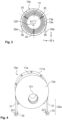
- FIG. 1 represents a cryostat 100 according to a first exemplary embodiment formed from two single-block parts 10a and 10b, joined together.
- Each single-piece part 10a, 10b comprises a succession of partitions including an interior partition 13a(1), 13b(1), an exterior partition 13a(3), 13b(3) and intermediate partitions 13a(2), 13b(2).
- External securing elements 20 make it possible to attach the cryostat to a satellite platform (not shown).
- the single-piece parts 10a and 10b When assembled, the single-piece parts 10a and 10b form a succession of closed metal screens 13, arranged around each other.
- the inner, intermediate and outer partitions of the single-piece parts thus form respectively an inner screen, intermediate screens and an outer screen.
- the smaller screen 13 located inside all the others, delimits a closed central enclosure 14 whose useful volume has a shape and dimensions adapted to the integration of one or more spatial components operating at low or very low temperatures (of the order of 60K for example).
- the inner metal screen that delimits the cryogenic enclosure is, for example, not watertight but forms a barrier to thermal radiation.
- the intermediate metal screens are, for example, not watertight but each form a barrier to thermal radiation.
- the body 10 generally has a symmetry of revolution around a longitudinal axis X.
- the single-block structural parts 10a and 10b each have (see Fig. 4 And 6 ) a cylindrical external partition 11a, 11b, open on one side according to a circular section and extended, on the other side by a conical portion 12a, 12b.
- the open circular side is provided with a circular fixing flange 111a and 111b. These flanges allow a junction and a fixing of the external partitions between them, for example via suitable tightening means such as bolts inserted into holes opposite.
- Each interior partition 13a(1) or respectively intermediate partition 13a(2) of the single-piece part 10a is arranged in the extension of an interior partition 13b(1) or respectively intermediate partition 13b(2) of the single-piece part 10b.
- the facing ends 130a and 130b of two interior or intermediate partitions located in the extension of one another remain at a distance from one another.
- the areas of rimpedement of these facing ends are offset longitudinally (i.e. these areas of rimpedement between partitions internal or intermediate are not located in the same transverse plane) to increase the barrier effect to thermal radiation and allow their installation while maintaining a reduced distance between successive screens.
- one of the facing ends 130a is extended in a U-shaped profile to create a baffle 130c with the other end 130b, and thus further increase the barrier effect to thermal radiation.
- one and/or the other of the facing ends could have been extended in an L-shaped profile.
- the enclosure 14 is cooled by two cold fingers 60 each arranged in a transverse passage 15 passing through the successive metal screens from the outer screen to the inner screen to arrive at the central enclosure 14.
- the body 10 of the cryostat thus comprises a succession of metal screens 13. These screens each act as an obstacle to thermal radiation and thus make it possible to keep the central enclosure 14 at regulated temperatures. All of the screens thus perform a thermal insulation function of the space component operating at cryogenic temperature relative to the external space environment and relative to the satellite platform.
- each single-piece part 10a, 10b comprises a plurality of successive partitions 13a, 13b, coaxial and spaced from each other which, when the single-piece parts are assembled, integrally form the successive screens.
- the partitions 13a, 13b of each single-piece part 10a, 10b may for example have identical shapes but at increasing sizes from the interior partition 13a(1), 13b(1) to the exterior partition 13a(3), 13b(3), passing through successive intermediate partitions 13a(2) and 13b(2).
- the partitions comprise cylindrical sections open at one end and closed at the other end by substantially conical sections.
- Each of the two single-block parts is a structural part of which each interior, intermediate and exterior partition has an annular portion.
- the annular portion of each partition is extended, in a single block, by a conical closed portion.
- each screen is composed of a conical portion extended by a portion of circular section itself coming in the extension of another circular portion extended by a conical portion.
- the two single-block parts include an identical number of partitions (eight in the example illustrated, i.e. six intermediate partitions), which are therefore combined in pairs, the number of partitions being able to vary depending on the insulation performance required.
- the paired intermediate partitions 13a(2) and 13b(2) have their portion of circular section opposite and in line with each other.
- the two single-piece parts 10a and 10b are also fixed together by the fixing flanges 111a, 111b at their external partition.
- the opposite and distant ends of the intermediate partitions also form, for example, a step.
- the end of one of the partitions for example the end 130a of the partition 13a(2), has a U-shaped section over its entire periphery, which defines a “female” part, inside which the end 130b, as the “male” part, of the other partition 13b(2) which has a straight section over its entire periphery, comes forward.
- These two ends remain at a distance from each other.
- the distribution of the male and female parts may be, for example, alternated between the partitions 13a, 13b of one and the other of the single-piece parts.
- baffle 130c which contributes to limiting the thermal radiative exchanges between two successive screens 13.
- This rimpedement zone is preferably carried out without contact, in order to limit friction between partitions under the effect of vibrations to which the cryostat is subjected.
- the successive metal screens thus create successive non-watertight obstructions.
- junctions i.e. the areas of ruzement
- the junctions follow, for example, a truncated cone arrangement, shown in a broken line on the figure 2 .
- the partitions 13a of the single-piece part 10a for example project relative to the plane containing the assembly face of the flange 111a, with an increasing projection length from the outer partition 13a(3) to the inner partition 13a(1).
- the partitions 13b of the single-piece part 10b visible on the figure 7 , are set back relative to the plane containing the assembly face of the flange 111b, with an increasing setback length from the outer partition 13b(3) to the inner partition 13b(1), such that the single-piece part 10b has a shape complementary to that of the single-piece part 10a, to allow a connection according to the configuration illustrated in figure 2 .
- the internal partitions 13a(1) and 13b(1) of the single-block structural parts 10a and 10b have an identical diameter D which delimits useful volumes 14a and 14b respectively, the association of which forms the central enclosure 14 receiving the spatial component to be cooled.
- cryostat 100 requires that the screens 13 be spaced apart from each other and maintained in this position.
- junction elements coming into contact with two successive screens are optimized to limit heat exchanges by conduction.
- the partitions 13a, 13b of each single-piece part 10a, 10b are connected to each other by internal junction elements 30, the arrangement of which makes it possible to optimize both the stiffness, the mechanical strength and the thermal conduction of the mechanical-thermal structure of the cryostat.
- the cryostat as a whole thus has good thermal resistance between the central enclosure 14 and the external environment.
- the cryostat also has good stiffness and mechanical strength taking into account the conditions of use of the cryostat, which can be extreme in terms of accelerations and vibrations experienced (in particular during the launch phase of the spacecraft in which the cryostat is installed).
- the cryostat as a whole thus has good thermal resistance between the central enclosure 14 and the external environment.
- the internal joining elements 30 may be distributed radially in several groups uniformly distributed over 360°.
- the internal joining elements 30 are distributed in three groups along three straight lines forming two by two an angle of 120° as shown in the figure 3 .
- external securing elements 20 hold the external screen, and therefore the body 10 of the cryostat, to a satellite platform (not shown).
- These external securing elements are optimized both in mechanical terms so as to guarantee good retention of the cryostat, and in thermal terms, so as to limit heat exchanges between the body 10 of the cryostat and its external environment (in particular said satellite platform).
- the external securing elements 20 have, for example, the shape of bipods and each comprise two V-shaped branches 21 which each end in a sole 22 allowing the cryostat to be fixed to the satellite platform, for example by suitable holes 221 which will receive specific fixing elements such as screws, washers and nuts.
- the cryostat 100 comprises three external bipods 20, two of which are bipods 20a secured to one of the single-piece parts 10a, and one bipod 20b secured to the other single-piece part 10b.
- the single-piece part fixed to two bipods is for example intended to support the space component operating at cryogenic temperature.
- the space component operating at cryogenic temperature such as an optical detector, operates through a front window 121, arranged at the top of a conical portion and closed by one or more panes.
- the external bipods 20 connect the cryostat 100 to a satellite platform, being physically in contact with the latter, and therefore constitute a conduction medium in which thermal diffusion is established between the platform and the cryostat.
- the internal junction elements 30, connecting the screens 13 together also provide mechanical support, while limiting thermal transfers by conduction, thanks to specific arrangements.
- Single-piece parts comprising several partitions, each forming a portion of screen, can be obtained by additive manufacturing (3D printing).
- the interior junction elements between screens are, for example, made from a single block with partitions, particularly if additive manufacturing is used.
- the construction material is for example invar or titanium.
- the geometric arrangement of the interior junction elements 30, between the screens 13 will for example be optimized and validated by series of simulations and mechanical and thermal tests carried out using computer tools and experimental installations.
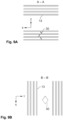
- FIGS 8 , 9A and 9B schematize a geometric arrangement of the internal junction elements 30 according to an exemplary embodiment of the invention.
- the screens 13 are shown in reduced number in these figures. This geometric arrangement was chosen on the basis of mechanical and thermal simulations; it makes it possible to obtain the expected results in terms of mechanical strength and thermal resistance.
- each group of internal junction elements comprises for example an internal junction element 30 between each pair of consecutive screens.
- the internal junction elements between screens are optimized in terms of section both to guarantee the mechanical strength of the cryostat and to limit thermal conduction (the smaller the section of the internal junction element 30, the lower the thermal conduction).
- each internal junction element 30 is formed by a double V-shaped rod, comprising two branches defining a plane. As explained below, this plane can be inclined relative to a transverse plane of the cryostat body.
- the internal junction elements 30 are for example inclined relative to a transverse plane (in this case, the bases of the Vs are all located in the same first transverse plane while the free ends of the branches of the Vs are located in transverse planes close to this first transverse plane), this inclination occurring alternately in the direction of one or the other of the axial ends of the body 10.
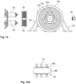
- each cold finger 60 passes through the screens to cool the central enclosure 14.
- Each cold finger is arranged at a distance from the screens.
- a thermally insulating coating 105 for example of the multilayer type, also called “MLI” (acronym for multi-layer insulation ), can be arranged, in the transverse passage 15, against each cold finger 60, thus reinforcing the thermal insulation of the cryostat.
- MMI multilayer type
- a thermally insulating bellows covering 106 for example made of polymer, can be arranged around each cold finger 60, in the transverse passage 15 and between the screens 13.
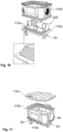
- the cryostat 100 is made up of three single-piece parts: a base 110a, an annular central part 110b and a cover 110c, which assemble to form the body of the cryostat.
- the single-piece parts each comprise a plurality of insulating partitions 113a, 113b and 113c, and have shapes adapted to the integration of a given spatial component 300.
- the shapes of the different single-piece parts 110a, 110b and 110c are also complementary so that each partition of a single-piece part is associated with one of the partitions of each of the two other single-piece parts to form a screen.
- the body of the cryostat 100 has a generally parallelepiped shape of which the central single-piece part 110b materializes the lateral faces, and of which the base 110a and the cover 110c materialize respectively the lower face and the upper face.
- the central monobloc part 110b comprises a succession of annular partitions 113b arranged at a distance from each other in a coaxial manner around a main axis X (materialized on the figure 15 ). It includes in particular an interior partition 113b(1) delimiting the enclosure 114 which receives the spatial component 300 operating at cryogenic temperature, intermediate partitions 113b(2), and an exterior partition 113b(3).
- the intermediate partitions and the interior partition are of similar shape and of increasing dimensions from the inside to the outside.
- the outer partition 113b(3) moves away in places from the outermost intermediate partition to form housings for receiving various functional organs of the cryostat such as electrical connection means.
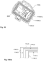
- the base 110a and the cover 110c comprise flat partitions 113a and 113c arranged at a distance from each other and having decreasing dimensions from the outside of the cryostat towards the inside, giving the base and the cover a pyramidal appearance.
- This pyramidal appearance clearly visible in the detail of the figure 16 , allows good accommodation of the cryostat.
- the internal partitions 113b(1), 113c(1) and intermediate partitions 113b(2), 113c(2) of the two single-piece parts are arranged in the vicinity of each other to form a screen closed in a non-tight manner, having their ends at a distance from each other.
- These two single-piece parts can correspond to the central single-piece part 110b and the cover 110c or to the central single-piece part 110b and the base 110a.
- the base 110a is provided with external bipods 20 (forming external securing elements between the cryostat and a satellite platform), which makes it possible to concentrate the force paths only in said base.
- the external bipods 20 and the internal joining elements can be made of the same material as the partitions 113a, 113b or 113c with which they are associated, for example of a metallic material having the appropriate thermal and mechanical properties, preferably titanium.
- Titanium offers a good compromise between mechanical properties (sufficient stiffness and strength) and thermal properties (relatively low thermal conductivity compared to other metals such as aluminum, for example). Titanium is also compatible with 3D printing.
- additive manufacturing such as laser powder bed fusion technology
- additive manufacturing allows the production of metal parts with fine, complex and intricate shapes, as is the case with single-piece parts (presence of a plurality of internal partitions connected by junction elements) with a precise configuration.
- cryostat according to the invention has at least the advantage of compactness and that of being able to accommodate one or more space components operating at cryogenic temperature of various shapes and sizes.
- thermal and mechanical computer simulations are performed to determine the number of screens 13, as well as their thicknesses and the thickness of the vacuum blades separating them, making it possible to achieve, without specific coatings or SLI ( Single Layer Insulation ) sheets or MLI ( Multi Layer Insulation ) multilayer insulation, thermal and mechanical performances equivalent to or superior to those of cryostats of the prior art.
- SLI Single Layer Insulation
- MLI Multi Layer Insulation
- this number has been estimated at seven screens under certain usual operating conditions.
- the number of screens can be adapted according to the missions, to comply with precise thermal specifications. For example, it may happen that the target temperatures in the internal volume of the cryostat are higher than the values mentioned above (60K and 100K), in which case a lower number of intermediate screens, for example two or three, would be sufficient to ensure the targeted thermal insulation.
- Another advantage of the invention is that, if one wishes to increase the thermal insulation performance of a cryostat, one can choose to add one or more screens to an already proven initial design, without this significantly impacting the design, qualification and manufacturing process of the cryostat. This is all the more true when 3D printing is used. Indeed, it proves less expensive and less restrictive to add an additional intermediate screen to the cryostat, which will be manufactured by 3D printing at the same time as the initial screens, than to insert single-layer SLI or multi-layer MLI insulation sheets between two successive screens of an initial cryostat for example.
- the spatial component 300 is positioned inside the first single-piece part 10a and fixed to the internal partition 13a(1) using suitable connecting means.
- An electrical connector 40 and cold fingers 60 are then installed on the body of the cryostat.
- At least one transverse channel is for example made in the successive screens up to the central enclosure for the passage of electrical power supply means and/or means of communication with the spatial component, which channel is closed at the level of the external screen by a thermally insulated connection interface.
- bellows 50 are provided around the cold fingers 60 to limit the effects of the micro-vibrations generated by the compressor on the fingers and to thermally insulate them.
- the cold fingers are inserted into passages 15 provided in the body, the passages 15 passing through all of the partitions 13a to the central enclosure 14.
- the cryostat can then be mounted on a satellite platform using its external securing elements (bipods) 20.
- This cryostat 200 comprises a single monobloc part 210a, a first series 210b of independent upper covers 213b and a second series 210c of independent lower covers 213c.
- the single-piece part 210a is for example made by 3D printing.
- the covers are for example made by 3D printing or by machining, then treated to add a gold plating to them.
- the single-piece part 210a is similar to the central single-piece part 110b of the exemplary embodiment of the Figures 15 to 18 in that it is generally annular and cylindrical with axis X, and in that it comprises a plurality of partitions, including an inner partition 213a(1), which partially delimits a central enclosure 214 intended to receive the spatial component to be maintained at very low temperatures, an outer partition 213a(3) and several - in the example two - intermediate partitions 213a(2). All the partitions are generally cylindrical, coaxial, spaced from each other; they have increasing dimensions going from the inner partition 213a(1) to the outer partition 213a(3).
- the partitions of the single-piece part 210a are made integral with each other by internal joining elements which can be double V-shaped rods as previously described for the example of embodiment of the figures 8 to 10 .
- the internal junction elements comprise several sets, including a set 230 and a set 231, of single rectilinear rods.
- the rods 230(1), 230(2) and 230(3) of the same set 230 are aligned and extend in a longitudinal plane containing the main axis X of the single-piece structural part 210a, in a direction inclined relative to a transverse plane.
- the rods of the same set extend in the same direction, which intersects the main axis X but forms an angle with this axis which is not equal to 90°.
- the directions in which the single rods are aligned form with a transverse plane (or with the X axis) angles which preferably vary from one set to another, so that the connection points between the outer partition 213a(3) and the rod 230(3) associated with said partition are located at heights (along the X axis) which vary from one set of rods to another.
- the straight lines along which the two sets of rods 230 and 231 are arranged have the same angle of inclination relative to the central axis X of the single-block part.
- the cryostat comprises a first series of upper covers 210b comprising an inner upper cover 213b(1), one or more - in the example two - intermediate upper covers 213b(2), and an outer upper cover 213b(3).
- the cryostat similarly comprises a second series of lower covers 210c, comprising an inner lower cover 213c(1), two intermediate lower covers 213c(2) and an outer lower cover 213c(3).
- the inner covers respectively upper 213b(1) and lower 213c(1) come in the axial extension of the inner partition 213a(1) of the single-piece part 210a and are fixed to the latter.
- the inner partition 213a(1) and the two inner covers 213b(1) and 213c(1) thus form an inner screen which delimits a closed enclosure 214 intended to accommodate the spatial component 300 to be cooled.
- the smaller of the lower intermediate covers 213c(2) and the smaller of the upper intermediate covers 213b(2) come in the axial extension of the smaller of the intermediate partitions 213a(2) of the single-piece part 210a and are fixed to said partition to form a first intermediate screen surrounding the inner screen.
- the larger of the lower intermediate covers 213c(2) and the larger of the upper intermediate covers 213b(2) come in the axial extension of the larger of the intermediate partitions 213a(2) of the single-piece part 210a and are fixed to said partition to form a second intermediate screen surrounding the first intermediate screen.
- outer covers respectively upper 213b(3) and lower 213c(3), come in the axial extension of the outer partition 213a(3) of the single-block part 210a and are fixed to this partition to form an outer screen.
- the covers are not linked together and therefore do not form structural monobloc parts capable of supporting and transmitting forces from one screen to another.
- the upper covers 213b(1) to 213b(3) and lower covers 213c(1) to 213c(3) are completely covered with a gold coating.
- This gold coating makes it possible to modulate the emissivity and absorptivity properties governing the radiative transfer and thus to optimize the radiative environment.
- This gold plating of the cover is for example obtained by electrolytic deposition on a part obtained by machining or 3D printing.
- the cryostat 200 further comprises external securing elements 20 in the form of bipods for securing it to a satellite platform. All the external bipods 20 of the cryostat 200 are fixed to the single-piece part 210a so that all the forces to which the space component operating at cryogenic temperature is subjected pass through this single-piece part, the rigidity of which is guaranteed by the internal junction elements between screens.
- connection interface 240 for the power supply and control of the instrument, as well as the recovery of the measurement data captured by the instrument can be carried by an external cover, for example the upper external cover 213b(3).
- cryostat also includes a device for cooling the enclosure 214, for example at least one insulated cold finger 260 which passes through the screens and can be extended by a thermal braid to reach and cool the central enclosure 214.
- a device for cooling the enclosure 214 for example at least one insulated cold finger 260 which passes through the screens and can be extended by a thermal braid to reach and cool the central enclosure 214.
- the cold finger may be insulated from the shields by a multi-layer insulation (MLI) sleeve, such as sleeve 105 illustrated in Figure 12A , the passage provided in the screens to receive the insulated cold finger preferably being sufficiently large so that the MLI sleeve is not in contact with the partitions 213a.
- MLI multi-layer insulation
- the cold finger may be insulated from the screens by a bellows polymer film, such as film 106 of the Figure 12B , coming into contact with the partitions 213a.
- the cryostat 200 further includes a transparent thermal screen 290 which fills and thermally insulates an opening 221 (see Fig. 19 ) arranged in the body of the cryostat opposite the space component operating at cryogenic temperature, such as an optical detector.
- a transparent thermal screen 290 which fills and thermally insulates an opening 221 (see Fig. 19 ) arranged in the body of the cryostat opposite the space component operating at cryogenic temperature, such as an optical detector.
- the cryostat according to the invention is not limited to the examples illustrated.
- the cryostat could comprise two single-piece parts and a single series of independent covers, for example a central single-piece part, similar to the annular central part 210a of the figure 19 , a lower one-piece part forming a base such as base 10a of Fig. 15 to 18 , and a series of upper independent covers such as covers 213b(1) to 213b(3) of the figure 19
- the external securing elements can either all be fixed to the central monobloc part, or all fixed to the lower monobloc part (base), or distributed over the two monobloc parts.
- the term “monobloc” in the expression “monobloc part” implies that this part is in the form of a single block such as for example a monolithic block obtained for example by 3D printing.
- a single-piece part is for example self-supporting and sufficiently rigid to absorb, in operation, all the forces undergone by the cryostat and the component it contains. Because it perfectly meets the requirements at very low temperatures and because it has improved mechanical behavior, the mechanical-thermal structure of the cryostat 100 or 200 according to the invention is particularly suitable for missions carrying ultrasensitive instrumentation, in particular for infrared detection, which must operate at extremely low temperatures to draw up precise maps of tiny temperature fluctuations, sometimes of the order of a hundred thousandth of a degree. Such instrumentation may include optical surfaces (lenses, mirrors, etc.), infrared sensors, bolometers, etc. Of course, this is not limiting to the applications of the cryostat of the invention, which can cooperate with other types of instruments or components operating at less extreme temperatures. The use of additive manufacturing technology makes it possible to manufacture this clever design while offering competitive cost and manufacturing lead time.
Landscapes
- Engineering & Computer Science (AREA)
- Manufacturing & Machinery (AREA)
- Aviation & Aerospace Engineering (AREA)
- Remote Sensing (AREA)
- Environmental & Geological Engineering (AREA)
- General Health & Medical Sciences (AREA)
- Toxicology (AREA)
- Environmental Sciences (AREA)
- Health & Medical Sciences (AREA)
- Biodiversity & Conservation Biology (AREA)
- Chemical & Material Sciences (AREA)
- Life Sciences & Earth Sciences (AREA)
- Materials Engineering (AREA)
- Mechanical Engineering (AREA)
- Containers, Films, And Cooling For Superconductive Devices (AREA)
Claims (16)
- Kryostat (100; 200) für mindestens eine Raumfahrtkomponente (300), die bei kryogener Temperatur funktioniert, wobei der Kryostat Folgendes umfasst:- ein zentrales Gehäuse (14; 114; 214), das geschlossen und gekühlt und dazu konfiguriert ist, die Raumfahrtkomponente aufzunehmen,- aufeinanderfolgende, voneinander beabstandete metallische Abschirmungen (13), darunter eine Innenabschirmung, eine Außenabschirmung und eine oder mehrere Zwischenabschirmungen, wobei die Innenabschirmung dazu konfiguriert ist, die Raumfahrtkomponente (300) zu tragen, und das zentrale Gehäuse (14; 114; 214) begrenzt, um die Raumfahrkomponente aufzunehmen, wobei die eine oder mehreren Zwischenabschirmungen und die Außenabschirmung umeinander herum angeordnet sind, um jeweils ein geschlossenes Volumen zu begrenzen, das die vorherige Abschirmung kleinerer Größe aufnimmt,- eine Kühlvorrichtung zum Abkühlen des zentralen Gehäuses auf eine kryogene Temperatur,- äußere Befestigungselemente (20), die an der Außenabschirmung befestigt sind, zum Befestigen des Kryostaten (100; 200) an einer Satellitenplattform,- innere Verbindungselemente zwischen den Abschirmungen (30; 230, 230(1), 230(2), 230(3), 231), die die Abschirmungen (13) voneinander beabstandet halten,wobei der Kryostat dadurch gekennzeichnet ist, dass er mindestens einen einteiligen Abschnitt (10a; 210a) umfasst, der eine Reihe von Trennwänden (13a; 213a) umfasst, darunter eine innere Trennwand (13a(1); 213a(1)), eine äußere Trennwand (13a(3); 213a(3)) und eine oder mehrere Zwischentrennwände (13a(2); 213a(2)), die jeweils einem Abschnitt der Innenabschirmung, einem Teil der Außenabschirmung und einem Teil der einen oder mehreren Zwischenabschirmungen entsprechen, wobei die Trennwände voneinander beabstandet sind und durch mindestens einen Abschnitt der inneren Verbindungselemente zwischen den Abschirmungen (30; 230, 230(1), 230(2), 230(3), 231) zusammengehalten werden.
- Kryostat nach Anspruch 1, wobei die Kühlvorrichtung einen oder mehrere Kühlfinger (60; 260) zum Kühlen des zentralen Gehäuses und einen Querkanal (15) für jeden der Kühlfinger umfasst, der durch die aufeinanderfolgenden metallischen Abschirmungen (13) bis zum zentralen Gehäuse (14; 114; 214) verläuft, um den Kühlfinger aufzunehmen, wobei der eine oder die mehreren Kühlfinger nicht in Kontakt mit den Abschirmungen stehen.
- Kryostat nach Anspruch 1 oder 2, wobei die inneren Verbindungselemente zwischen den Abschirmungen (30; 230, 230(1), 230(2), 230(3), 231) zwischen den aufeinanderfolgenden Abschirmungen angeordnet und dazu konfiguriert sind, alleine für sich eine mechanische Festigkeit zwischen der Außenabschirmung und der Innenabschirmung zu gewährleisten, wobei die inneren Verbindungselemente dazu konfiguriert sind, bestimmten Kräften standzuhalten, die mindestens durch eine Masse der Raumfahrtkomponente (300) und Massen der Abschirmungen (13) induziert werden.
- Kryostat nach einem der Ansprüche 1 bis 3, wobei die inneren Verbindungselemente zwischen den Abschirmungen doppelte V-förmige Stäbe (30) zwischen den aufeinanderfolgenden Abschirmungen umfassen, wobei die Vs winkelmäßig um eine Hauptachse (X) oder einen zentralen Punkt des Kryostaten in mindestens drei radiale Richtungen verteilt sind.
- Kryostat nach einem der Ansprüche 1 bis 4, wobei die inneren Verbindungselemente zwischen den Abschirmungen mehrere Sätze (230, 231) einfacher Stäbe (230(1), 230(2), 230(3)) umfassen, wobei die einfachen Stäbe derselben Anordnung entlang einer geraden Linie ausgerichtet sind, die durch die Abschirmungen verläuft, wobei die geraden Linien zweier unterschiedlicher Anordnungen (230, 231) nicht parallel und nicht koplanar zueinander sind.
- Kryostat nach einem der Ansprüche 1 bis 5, wobei die inneren Verbindungselemente zwischen den Abschirmungen (30; 230(1), 230(2), 230(3), 231) mindestens teilweise in einem einzigen Block mit mindestens einem Abschnitt der Abschirmungen (13) ausgebildet sind.
- Kryostat nach einem der Ansprüche 1 bis 6, wobei der einteilige Abschnitt durch additive Fertigung ausgebildet ist.
- Kryostat nach Anspruch 1 bis 7, dadurch gekennzeichnet, dass:- der Kryostat eine Vielzahl von einteiligen Abschnitten (10a, 10b; 110a, 110b, 110c) umfasst, die jeweils eine innere Trennwand (13a(1), 13b(1); 113a(1), 113b(1), 113c(1)), eine äußere Trennwand (13a(3), 13b(3); 113a(3), 113b(3), 113c(3)) und eine oder mehrere Zwischentrennwände (13a(2), 13b(2); 113a(2), 113b(2), 113c(2)) aufweist, wobei die Trennwände zweier unterschiedlicher einteiliger Abschnitte unter den einteiligen Abschnitten zwei unterschiedlichen Abschnitten der Abschirmungen entsprechen,- die Zwischentrennwände (13a(2), 13b(2); 113b(2), 113c(2); 113a(2), 113b(2)) oder die inneren Trennwände (13a(1), 13b(1); 113b(1), 113c(1); 113a(1), 113b(1)) aus zwei unterschiedlichen und benachbarten einteiligen Abschnitten (10a, 10b; 110b, 110c; 110a, 110b) aus der Vielzahl von einteiligen Abschnitten, die eine Verlängerung voneinander darstellen, nicht verbindbar sind,- die äußeren Trennwände (13a(3), 13b(3); 113b(3), 113c(3); 113a(3), 113b(3)) aus zwei verschiedenen und benachbarten einteiligen Abschnitten aus der Vielzahl von einteiligen Abschnitten, die eine Verlängerung voneinander darstellen, verbindbar und aneinander befestigt sind.
- Kryostat nach Anspruch 8, wobei die Zwischentrennwände (13a(2), 13b(2)) oder die inneren Trennwände (13a(1), 13b(1)), die eine Verlängerung voneinander darstellen, einander zugewandte Enden aufweisen, wobei mindestens eines der zugewandten Enden eine Aussparung aufweist, um mit dem anderen zugewandten Ende eine Aufnahmeverbindung (130c) zu bilden.
- Kryostat nach einem der Ansprüche 1 bis 9, wobei die äußeren Befestigungselemente (20) entweder alle an der äußeren Trennwand nur eines der einteiligen Abschnitte befestigt sind oder an den äußeren Trennwänden mehrerer der einzelnen Abschnitte verteilt sind.
- Kryostat nach einem der Ansprüche 1 bis 10, dadurch gekennzeichnet, dass mindestens einer (110b; 210a) der einteiligen Abschnitte ein ringförmiger Strukturabschnitt ist, von dem jede innere Trennwand (113b(1); 213a(1)), Zwischentrennwand (113b(2); 213a(2)) und äußere Trennwand (113b(3); 213a(3)) ringförmig ist.
- Kryostat nach einem der Ansprüche 1 bis 11, dadurch gekennzeichnet, dass jede der Abschirmungen des Kryostaten vollständig durch die Montage der Trennwände der einteiligen Abschnitte (10a, 10b; 110a, 110b, 110c) gebildet ist.
- Kryostat nach Anspruch 11, wobei:- der Kryostat mindestens eine Reihe (210b, 210c) unabhängiger Abdeckungen umfasst, darunter für jede Reihe eine innere Abdeckung (213b(1), 213c(1)), eine äußere Abdeckung (213b(3), 213c(3)) und eine oder mehrere Zwischenabdeckungen (213b(2), 213c(2)), wobei jede Reihe von Abdeckungen jeweils einem anderen Abschnitt der Abschirmungen entspricht, wobei die Abdeckungen derselben Reihe ineinander mit einem Abstand untereinander ohne innere Verbindungselemente angeordnet sind,- jede der Abdeckungen (213b(1), 213b(2), 213b(3), 213c(1), 213c(2), 213c(3)) an einer der Trennwände (213a(1), 213a(2), 213a(3)) des ringförmigen Strukturabschnitts (210a) befestigt ist und diese verlängert, wobei jede der Abschirmungen des Kryostaten somit vollständig durch mindestens eine der Trennwände des ringförmigen Strukturabschnitts und durch die eine der Abdeckungen jeder Reihe gebildet wird.
- Kryostat nach Anspruch 13, wobei mindestens ein Abschnitt jeder der Abdeckungen (213b(1), 213b(2), 213b(3), 213c(1), 213c(2), 213c(3)) mit einer goldenen Beschichtung versehen ist.
- Kryostat nach einem der Ansprüche 2 bis 14, wobei jeder der Kühlfinger (60; 260) gegenüber den Abschirmungen thermisch isoliert ist, wobei an mindestens einem der Kühlfinger (60) im Querkanal (15) des Kühlfingers eine thermisch isolierende Beschichtung angeordnet ist und/oder um mindestens einen der Kühlfinger (60) herum, im Querkanal (15) des Kühlfingers und zwischen den Abschirmungen (13), eine thermisch isolierende harmonikaförmige Abdeckung angeordnet ist.
- Raumfahrzeug, dadurch gekennzeichnet, dass es eine Raumfahrtkomponente (300) umfasst, die bei kryogener Temperatur funktioniert und in einem Kryostaten nach einem der Ansprüche 1 bis 15 angeordnet ist, wobei der Kryostat an einer Plattform des Raumfahrzeugs befestigt ist.
Applications Claiming Priority (2)
| Application Number | Priority Date | Filing Date | Title |
|---|---|---|---|
| FR2112876A FR3129924B1 (fr) | 2021-12-02 | 2021-12-02 | cryostat pour un composant spatial |
| PCT/FR2022/052191 WO2023099837A1 (fr) | 2021-12-02 | 2022-11-29 | Cryostat pour un composant spatial |
Publications (3)
| Publication Number | Publication Date |
|---|---|
| EP4399152A1 EP4399152A1 (de) | 2024-07-17 |
| EP4399152B1 true EP4399152B1 (de) | 2025-01-22 |
| EP4399152C0 EP4399152C0 (de) | 2025-01-22 |
Family
ID=80787445
Family Applications (1)
| Application Number | Title | Priority Date | Filing Date |
|---|---|---|---|
| EP22840244.2A Active EP4399152B1 (de) | 2021-12-02 | 2022-11-29 | Kryostat für ein raumbauteil |
Country Status (3)
| Country | Link |
|---|---|
| EP (1) | EP4399152B1 (de) |
| FR (1) | FR3129924B1 (de) |
| WO (1) | WO2023099837A1 (de) |
Family Cites Families (5)
| Publication number | Priority date | Publication date | Assignee | Title |
|---|---|---|---|---|
| US3253423A (en) * | 1962-10-22 | 1966-05-31 | Philco Corp | Cryogenic cooling arrangement for space vehicles |
| US3355050A (en) * | 1964-09-02 | 1967-11-28 | Neil P Ruzic | Lunar cryostat |
| US3369370A (en) * | 1965-12-03 | 1968-02-20 | Hughes Aircraft Co | Method of detector cooling and device therefor |
| FR2410211A1 (fr) | 1977-11-25 | 1979-06-22 | Anvar | Cryostat a cryogene liquide muni d'un dispositif monobloc de suspension ultra-rigide compatible avec l'ancrage thermique des ecrans de radiation |
| US10408378B2 (en) * | 2017-07-17 | 2019-09-10 | Raytheon Company | Three-dimensional multi-shell insulation |
-
2021
- 2021-12-02 FR FR2112876A patent/FR3129924B1/fr active Active
-
2022
- 2022-11-29 EP EP22840244.2A patent/EP4399152B1/de active Active
- 2022-11-29 WO PCT/FR2022/052191 patent/WO2023099837A1/fr not_active Ceased
Also Published As
| Publication number | Publication date |
|---|---|
| EP4399152A1 (de) | 2024-07-17 |
| FR3129924B1 (fr) | 2024-08-23 |
| WO2023099837A1 (fr) | 2023-06-08 |
| EP4399152C0 (de) | 2025-01-22 |
| FR3129924A1 (fr) | 2023-06-09 |
Similar Documents
| Publication | Publication Date | Title |
|---|---|---|
| EP3313734B1 (de) | Satellit mit zylindrischem hauptkörper, stapel mit solch einem satelliten und startanordnung für solch einen satelliten | |
| EP2019038B1 (de) | Sonnenschutzvorrichtung für ein Instrument im Weltraum | |
| EP3259189B1 (de) | Künstlicher satellit | |
| EP4399152B1 (de) | Kryostat für ein raumbauteil | |
| FR2638023A1 (fr) | Dispositif cryostatique pour detecteur de rayonnements | |
| WO2012164523A1 (fr) | Detecteur spectroscopique et procede correspondant. | |
| FR3031502A1 (fr) | Ensemble de pointage d'un instrument | |
| EP3067676A2 (de) | Vorrichtung zur strahlungserfassung, die eine einkapselungsstruktur mit verbesserter mechanischer festigkeit umfasst | |
| Cheimets et al. | SDO-AIA telescope design | |
| EP3392887A1 (de) | System zur erzeugung eines vektoriellen magnetfelds | |
| EP2861928B1 (de) | Temperaturregelungsvorrichtung | |
| EP0490727B1 (de) | Vorrichtung und Tiegel zur Abscheidung aus der Gasphase | |
| EP3581781B1 (de) | Antriebssystem eines luftfahrzeugs mit einer befestigten innenstruktur, die einen auslassschlitz aufweist | |
| EP0127540B1 (de) | Vorrichtung zum Aufhängen einer Struktur | |
| FR3000362A1 (fr) | Bloc d'extraction d'air pour baie avionique | |
| Crumrine | BICEP Array: Searching for Signals of Inflation from the South Pole | |
| EP4040120A1 (de) | Architektur für brennebene | |
| EP4045413B1 (de) | Gedämpfte, bearbeitete primärstruktur für ein raumfahrzeug, satellit mit dieser primärstruktur und verfahren zur herstellung eines solchen satelliten | |
| EP2672492B1 (de) | Mechanische Halterung für thermische oder elektrische Systeme | |
| EP3545184B1 (de) | Verbessertes gehäuse für kryogenen körper | |
| FR3145209A1 (fr) | Dispositif de détection de rayonnement électromagnétique | |
| FR3122252A1 (fr) | Structure thermomécanique pour plan focal d’instrument d’observation spatiale | |
| FR2886724A1 (fr) | Centrale de reperage pour engin mobile, integrant une plate-forme inertielle gyrostabilisee et un dispositif telescopique de visee stellaire. | |
| Holmes et al. | Modeling effects of common molecular contaminants on the Euclid infrared detectors | |
| FR2879396A1 (fr) | Enceinte a vide pour le ralentissement d'atomes dans un generateur d'atomes lents |
Legal Events
| Date | Code | Title | Description |
|---|---|---|---|
| STAA | Information on the status of an ep patent application or granted ep patent |
Free format text: STATUS: UNKNOWN |
|
| STAA | Information on the status of an ep patent application or granted ep patent |
Free format text: STATUS: THE INTERNATIONAL PUBLICATION HAS BEEN MADE |
|
| PUAI | Public reference made under article 153(3) epc to a published international application that has entered the european phase |
Free format text: ORIGINAL CODE: 0009012 |
|
| STAA | Information on the status of an ep patent application or granted ep patent |
Free format text: STATUS: REQUEST FOR EXAMINATION WAS MADE |
|
| 17P | Request for examination filed |
Effective date: 20240408 |
|
| AK | Designated contracting states |
Kind code of ref document: A1 Designated state(s): AL AT BE BG CH CY CZ DE DK EE ES FI FR GB GR HR HU IE IS IT LI LT LU LV MC ME MK MT NL NO PL PT RO RS SE SI SK SM TR |
|
| GRAP | Despatch of communication of intention to grant a patent |
Free format text: ORIGINAL CODE: EPIDOSNIGR1 |
|
| STAA | Information on the status of an ep patent application or granted ep patent |
Free format text: STATUS: GRANT OF PATENT IS INTENDED |
|
| RIC1 | Information provided on ipc code assigned before grant |
Ipc: B22F 5/10 20060101ALI20240730BHEP Ipc: B33Y 80/00 20150101ALI20240730BHEP Ipc: F17C 3/08 20060101ALI20240730BHEP Ipc: B64G 1/66 20060101ALI20240730BHEP Ipc: B64G 1/50 20060101AFI20240730BHEP |
|
| DAV | Request for validation of the european patent (deleted) | ||
| DAX | Request for extension of the european patent (deleted) | ||
| INTG | Intention to grant announced |
Effective date: 20240809 |
|
| GRAS | Grant fee paid |
Free format text: ORIGINAL CODE: EPIDOSNIGR3 |
|
| GRAA | (expected) grant |
Free format text: ORIGINAL CODE: 0009210 |
|
| STAA | Information on the status of an ep patent application or granted ep patent |
Free format text: STATUS: THE PATENT HAS BEEN GRANTED |
|
| AK | Designated contracting states |
Kind code of ref document: B1 Designated state(s): AL AT BE BG CH CY CZ DE DK EE ES FI FR GB GR HR HU IE IS IT LI LT LU LV MC ME MK MT NL NO PL PT RO RS SE SI SK SM TR |
|
| REG | Reference to a national code |
Ref country code: GB Ref legal event code: FG4D Free format text: NOT ENGLISH |
|
| REG | Reference to a national code |
Ref country code: CH Ref legal event code: EP |
|
| REG | Reference to a national code |
Ref country code: DE Ref legal event code: R096 Ref document number: 602022009874 Country of ref document: DE |
|
| REG | Reference to a national code |
Ref country code: IE Ref legal event code: FG4D Free format text: LANGUAGE OF EP DOCUMENT: FRENCH |
|
| U01 | Request for unitary effect filed |
Effective date: 20250211 |
|
| U07 | Unitary effect registered |
Designated state(s): AT BE BG DE DK EE FI FR IT LT LU LV MT NL PT RO SE SI Effective date: 20250217 |
|
| PG25 | Lapsed in a contracting state [announced via postgrant information from national office to epo] |
Ref country code: RS Free format text: LAPSE BECAUSE OF FAILURE TO SUBMIT A TRANSLATION OF THE DESCRIPTION OR TO PAY THE FEE WITHIN THE PRESCRIBED TIME-LIMIT Effective date: 20250422 |
|
| PG25 | Lapsed in a contracting state [announced via postgrant information from national office to epo] |
Ref country code: PL Free format text: LAPSE BECAUSE OF FAILURE TO SUBMIT A TRANSLATION OF THE DESCRIPTION OR TO PAY THE FEE WITHIN THE PRESCRIBED TIME-LIMIT Effective date: 20250122 |
|
| PG25 | Lapsed in a contracting state [announced via postgrant information from national office to epo] |
Ref country code: ES Free format text: LAPSE BECAUSE OF FAILURE TO SUBMIT A TRANSLATION OF THE DESCRIPTION OR TO PAY THE FEE WITHIN THE PRESCRIBED TIME-LIMIT Effective date: 20250122 |
|
| PG25 | Lapsed in a contracting state [announced via postgrant information from national office to epo] |
Ref country code: NO Free format text: LAPSE BECAUSE OF FAILURE TO SUBMIT A TRANSLATION OF THE DESCRIPTION OR TO PAY THE FEE WITHIN THE PRESCRIBED TIME-LIMIT Effective date: 20250422 Ref country code: IS Free format text: LAPSE BECAUSE OF FAILURE TO SUBMIT A TRANSLATION OF THE DESCRIPTION OR TO PAY THE FEE WITHIN THE PRESCRIBED TIME-LIMIT Effective date: 20250522 |
|
| PG25 | Lapsed in a contracting state [announced via postgrant information from national office to epo] |
Ref country code: HR Free format text: LAPSE BECAUSE OF FAILURE TO SUBMIT A TRANSLATION OF THE DESCRIPTION OR TO PAY THE FEE WITHIN THE PRESCRIBED TIME-LIMIT Effective date: 20250122 |
|
| PG25 | Lapsed in a contracting state [announced via postgrant information from national office to epo] |
Ref country code: GR Free format text: LAPSE BECAUSE OF FAILURE TO SUBMIT A TRANSLATION OF THE DESCRIPTION OR TO PAY THE FEE WITHIN THE PRESCRIBED TIME-LIMIT Effective date: 20250423 |
|
| PG25 | Lapsed in a contracting state [announced via postgrant information from national office to epo] |
Ref country code: SM Free format text: LAPSE BECAUSE OF FAILURE TO SUBMIT A TRANSLATION OF THE DESCRIPTION OR TO PAY THE FEE WITHIN THE PRESCRIBED TIME-LIMIT Effective date: 20250122 |
|
| PG25 | Lapsed in a contracting state [announced via postgrant information from national office to epo] |
Ref country code: CZ Free format text: LAPSE BECAUSE OF FAILURE TO SUBMIT A TRANSLATION OF THE DESCRIPTION OR TO PAY THE FEE WITHIN THE PRESCRIBED TIME-LIMIT Effective date: 20250122 |
|
| PG25 | Lapsed in a contracting state [announced via postgrant information from national office to epo] |
Ref country code: SK Free format text: LAPSE BECAUSE OF FAILURE TO SUBMIT A TRANSLATION OF THE DESCRIPTION OR TO PAY THE FEE WITHIN THE PRESCRIBED TIME-LIMIT Effective date: 20250122 |
|
| U1N | Appointed representative for the unitary patent procedure changed after the registration of the unitary effect |
Representative=s name: SANTARELLI; FR |
|
| PLBE | No opposition filed within time limit |
Free format text: ORIGINAL CODE: 0009261 |
|
| STAA | Information on the status of an ep patent application or granted ep patent |
Free format text: STATUS: NO OPPOSITION FILED WITHIN TIME LIMIT |
|
| 26N | No opposition filed |
Effective date: 20251023 |
|
| U20 | Renewal fee for the european patent with unitary effect paid |
Year of fee payment: 4 Effective date: 20251127 |