EP4398528A1 - Wireless communication system, wireless communication method, and wireless communication transmission device - Google Patents
Wireless communication system, wireless communication method, and wireless communication transmission device Download PDFInfo
- Publication number
- EP4398528A1 EP4398528A1 EP21956048.9A EP21956048A EP4398528A1 EP 4398528 A1 EP4398528 A1 EP 4398528A1 EP 21956048 A EP21956048 A EP 21956048A EP 4398528 A1 EP4398528 A1 EP 4398528A1
- Authority
- EP
- European Patent Office
- Prior art keywords
- transmission power
- transmission
- error rate
- wireless communication
- reception
- Prior art date
- Legal status (The legal status is an assumption and is not a legal conclusion. Google has not performed a legal analysis and makes no representation as to the accuracy of the status listed.)
- Pending
Links
Images





Classifications
-
- H—ELECTRICITY
- H04—ELECTRIC COMMUNICATION TECHNIQUE
- H04L—TRANSMISSION OF DIGITAL INFORMATION, e.g. TELEGRAPHIC COMMUNICATION
- H04L27/00—Modulated-carrier systems
- H04L27/18—Phase-modulated carrier systems, i.e. using phase-shift keying
- H04L27/20—Modulator circuits; Transmitter circuits
-
- H—ELECTRICITY
- H04—ELECTRIC COMMUNICATION TECHNIQUE
- H04L—TRANSMISSION OF DIGITAL INFORMATION, e.g. TELEGRAPHIC COMMUNICATION
- H04L27/00—Modulated-carrier systems
- H04L27/0008—Modulated-carrier systems arrangements for allowing a transmitter or receiver to use more than one type of modulation
-
- H—ELECTRICITY
- H04—ELECTRIC COMMUNICATION TECHNIQUE
- H04W—WIRELESS COMMUNICATION NETWORKS
- H04W52/00—Power management, e.g. Transmission Power Control [TPC] or power classes
- H04W52/04—Transmission power control [TPC]
- H04W52/18—TPC being performed according to specific parameters
- H04W52/20—TPC being performed according to specific parameters using error rate
-
- H—ELECTRICITY
- H04—ELECTRIC COMMUNICATION TECHNIQUE
- H04W—WIRELESS COMMUNICATION NETWORKS
- H04W52/00—Power management, e.g. Transmission Power Control [TPC] or power classes
- H04W52/04—Transmission power control [TPC]
- H04W52/18—TPC being performed according to specific parameters
- H04W52/24—TPC being performed according to specific parameters using SIR [Signal to Interference Ratio] or other wireless path parameters
- H04W52/241—TPC being performed according to specific parameters using SIR [Signal to Interference Ratio] or other wireless path parameters taking into account channel quality metrics, e.g. SIR, SNR, CIR or Eb/lo
-
- H—ELECTRICITY
- H04—ELECTRIC COMMUNICATION TECHNIQUE
- H04W—WIRELESS COMMUNICATION NETWORKS
- H04W52/00—Power management, e.g. Transmission Power Control [TPC] or power classes
- H04W52/04—Transmission power control [TPC]
- H04W52/52—Transmission power control [TPC] using AGC [Automatic Gain Control] circuits or amplifiers
Definitions
- 64 symbols arranged in a lattice pattern are defined by changing and adjusting amplitudes of two carrier waves independent of each other.
- a point on constellation coordinates at which each of the 64 symbols is defined is referred to as a "signal point”.
- a point on the constellation coordinates of each data signal to be actually transmitted is referred to as a "reception point”.
- the transmission device 14 of the comparative example if the transmission power is limited to the linear region of the transmission signal amplifier 22, it is possible to prevent distortion from occurring in the constellation of the reception points. Thus, by applying such a limitation, it is possible to prevent erroneous recognition of data in the reception device 12. However, in that case, a situation occurs in which an amplification capability of the transmission signal amplifier 22 cannot be sufficiently utilized.
- Fig. 5 is a block diagram for explaining a configuration of the transmission device 10 in the present embodiment. Note that, in Fig. 5 , the same elements as those included in the transmission device 14 of the comparative example (see Fig. 2 ) are denoted by the same reference signs, and description thereof will be omitted or simplified.
- Fig. 6 illustrates an arithmetic expression (1) of the symbol error rate SER and an arithmetic expression (2) of the bit error rate BER.
- M is the number of signal points constituting the constellation
- m is the number of bits of each signal point.
- SER Ps is a function of " ⁇ s”.
- BER Pb is a function of " ⁇ b”.
- SER Ps( ⁇ s) can be approximately obtained by ⁇ M Q( ⁇ ( ⁇ M ⁇ s)) using a Q function.
- BER Pb( ⁇ b) can be approximately obtained by ( ⁇ M /m)Q( ⁇ (m ⁇ M ⁇ b)).
- the reception device 12 calculates an SNR ( ⁇ s, ⁇ b) on the basis of strength of the signal. Then, the calculated SNR is returned to the transmission device 10. The transmission device 10 acquires the SNR returned in this manner (step 102).
- the transmission device 10 calculates SER and BER that will be achieved under the current transmission power (step 104). Specifically, a constellation corresponding to the current transmission power is read, and ⁇ M and ⁇ M corresponding to the constellation are determined. Then, SER and BER are calculated by the expression (1) or (2) on the basis of the number of bits m unique to the modulation scheme, the SNR ( ⁇ s, ⁇ b) acquired from the reception device 12, and ⁇ M and ⁇ M described above.
- the wireless communication system uses SER as the evaluation index, it is determined whether SER is less than or equal to the requirement threshold. In addition, in a case where the wireless communication system uses BER as the evaluation index, it is determined whether BER is less than or equal to the requirement threshold.
- the routine of this time is ended in a state where the transmission power is maintained as power for communication.
- step 106 determines whether or not search for all transmission powers possible is ended (step 108). For example, in a case where the transmission power is switchable in N levels, it is determined whether the processing of step 102 to 106 has been executed for all of the N levels.
- step 100 and subsequent steps are started again.
- step 110 the transmission power is changed in accordance with a predetermined rule. Thereafter, the processing of step 102 and subsequent steps is repeated.
- the SNR in the reception device 12 changes, and magnitude of distortion superimposed on the constellation changes.
- the routine illustrated in Fig. 9 it is possible to find the transmission power at which the error rate (SER, BER) can clear the requirement.
- the error rate SER, BER
- use of the transmission power belonging to the non-linear region can also be allowed. Therefore, according to the present embodiment, it is possible to efficiently achieve excellent communication quality by effectively utilizing the capability of the transmission signal amplifier 22 within a range in which erroneous recognition of data does not occur.
- a transmission unit of the reception device 12 has a configuration for functioning substantially similarly to the transmission unit of the transmission device 10.
- a reception unit of the reception device 12 has a configuration for functioning substantially similarly to the reception unit of the transmission device 10 except for an SNR estimation unit 68 and a likelihood calculation unit 70.
- the likelihood calculation unit 70 calculates a likelihood for a reception point on the basis of the transmission power used in the transmission device 10.
- the modulation scheme and the input-output characteristic of the transmission signal amplifier 22 are shared between the transmission device 10 and the reception device 12.
- the transmission device 10 successively provides information on the transmission power used for communication to the reception device 12.
- the reception device 12 performs likelihood calculation on the basis of the constellation reproduced depending on the transmission power.
- the reception device 12 performs likelihood calculation on the assumption of the distortion. Therefore, according to the present embodiment, in a case where the transmission device 10 uses the transmission power determined to be usable on the basis of the error rate (SER, BER), it is possible to effectively avoid occurrence of a situation in which data is erroneously recognized on responsibility of the reception device 12 side.
- SER error rate
- the search for the transmission power is ended when the transmission power at which the error rate (SER, BER) clears a desired requirement is found.
- the present disclosure is not limited thereto.
- the search may be continued even after a condition that the error rate clears the requirement is found, and the transmission power with the smallest error rate may be found.
Landscapes
- Engineering & Computer Science (AREA)
- Signal Processing (AREA)
- Computer Networks & Wireless Communication (AREA)
- Quality & Reliability (AREA)
- Transmitters (AREA)
Abstract
Description
- The present disclosure relates to a wireless communication system, a wireless communication method, and a wireless communication transmission device, and more particularly, to a wireless communication system, a wireless communication method, and a wireless communication transmission device using a single-carrier multi-value modulation scheme.
-
Non Patent Literature 1 below discloses a technique related to a wireless communication system using a single-carrier multi-value modulation scheme. In wireless communication using a single-carrier multi-value modulation scheme, a signal to noise ratio (SNR) can be increased as transmission power is increased. - On the other hand, an amplifier of a transmission signal exhibits a linear input-output characteristic in a region where input power is small, but generally exhibits a non-linear characteristic in a region where the power is large. For this reason, in the wireless communication, as the transmission power increases, distortion is more likely to occur in the transmission signal.
- To avoid an influence of such distortion,
Non Patent Literature 1 discloses a technique for keeping transmission power within a linear region of an amplifier. In this case, since distortion is not superimposed on the transmission signal, it is possible to correctly process the signal in the reception device, and it is possible to effectively prevent erroneous transmission of data. - Non Patent Literature 1: High-Speed Satellite Mobile Communications: Technologies and Challenges, MOHAMED IBNKAHLA, QUAZI MEHBUBAR RAHMAN, AHMED IYANDA SULYMAN, HISHAM ABDULHUSSEIN AL-ASADY, JUN YUAN, AND AHMED SAFWAT, p312-339, PROCEEDINGS OF THE IEEE, VOL. 92, NO. 2, February 2004
- By the way, even if the transmission power belongs to a non-linear region of the amplifier, if the distortion superimposed on the transmission signal is not excessive, erroneous recognition of data does not occur in the reception device. On the other hand, the technique of
Non Patent Literature 1 described above uniformly keeps the transmission power to the linear region of the amplifier, and can also be evaluated as imposing an excessive limitation on a capability of the amplifier. - The present disclosure has been made in view of the above problem, and a first object thereof is to provide a wireless communication system that achieves excellent communication quality by effectively utilizing a capability of an amplifier of a transmission device within a range in which erroneous recognition of data does not occur.
- In addition, a second object of the present disclosure is to provide a wireless communication method that achieves excellent communication quality by effectively utilizing a capability of an amplifier of a transmission device within a range in which erroneous recognition of data does not occur.
- In addition, a third object of the present disclosure is to provide a wireless communication transmission device capable of achieving excellent communication quality by effectively utilizing a capability of an amplifier within a range in which erroneous recognition of data does not occur.
- To achieve the above objects, a first aspect is desirably a wireless communication system including a transmission device and a reception device that perform wireless communication by using a single-carrier multi-value modulation scheme, in which
the transmission device includes: - a transmission signal amplifier enabled to vary transmission power;
- a transmission power control unit that controls transmission power used by the transmission signal amplifier;
- an error rate characteristic estimation unit that estimates an error rate of a reception signal in the reception device; and
- a reception unit that receives information on an SNR in the reception device,
- the error rate characteristic estimation unit is configured to execute:
- processing of estimating a constellation corresponding to the modulation scheme and reflecting a specification regarding an input-output characteristic of the transmission signal amplifier on the basis of the transmission power; and
- processing of estimating the error rate on the basis of a characteristic of the constellation and the SNR, and
- the transmission power control unit is configured to execute transmission power control processing of controlling the transmission power such that the error rate satisfies a predetermined requirement.
- In addition, a second aspect is desirably a wireless communication method using a transmission device and a reception device that perform wireless communication by using a single-carrier multi-value modulation scheme,
- the transmission device including a transmission signal amplifier enabled to vary transmission power,
- the wireless communication method including:
- a step, by the transmission device, of estimating a constellation corresponding to the modulation scheme and reflecting a specification regarding an input-output characteristic of the transmission signal amplifier on the basis of the transmission power;
- a step, by the transmission device, of receiving information on an SNR in the reception device;
- a step, by the transmission device, of estimating an error rate of a reception signal in the reception device on the basis of a characteristic of the constellation and the SNR; and
- a step, by the transmission device, of controlling the transmission power such that the error rate satisfies a predetermined requirement.
- In addition, a third aspect is desirably a wireless communication transmission device that performs wireless communication by using a single-carrier multi-value modulation scheme, the wireless communication transmission device including:
- a transmission signal amplifier enabled to vary transmission power;
- a transmission power control unit that controls transmission power used by the transmission signal amplifier;
- an error rate characteristic estimation unit that estimates an error rate of a reception signal in a reception device of a communication partner; and
- a reception unit that receives information on an SNR in the reception device, in which
- the error rate characteristic estimation unit is configured to execute:
- processing of estimating a constellation corresponding to the modulation scheme and reflecting a specification regarding an input-output characteristic of the transmission signal amplifier on the basis of the transmission power; and
- processing of estimating the error rate on the basis of a characteristic of the constellation and the SNR, and
- the transmission power control unit is configured to execute processing of controlling the transmission power such that the error rate satisfies a predetermined requirement.
- According to the first to third aspects, it is possible to effectively utilize the capability of the amplifier of the transmission device within a range in which erroneous recognition of data does not occur. Therefore, according to the present aspects, it is possible to achieve wireless communication having excellent quality while suppressing an amount of capital investment.
-
-
Fig. 1 is a diagram for explaining an overall configuration of a wireless communication system of a first embodiment of the present disclosure. -
Fig. 2 is a diagram for explaining a configuration of a transmission device to be compared with a transmission device in the first embodiment of the present disclosure. -
Fig. 3 is a diagram illustrating an input-output characteristic of an amplifier built in the transmission device. -
Fig. 4 is a diagram illustrating a state in which distortion occurs in a constellation with an increase in transmission power. -
Fig. 5 is a block diagram for explaining a configuration of the transmission device in the first embodiment of the present disclosure. -
Fig. 6 illustrates arithmetic expressions used by the transmission device illustrated inFig. 5 to calculate a symbol error rate SER and a bit error rate BER, respectively. -
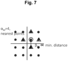
Fig. 7 is a diagram for explaining a concept of the number of nearest points αM. -
Fig. 8 is a diagram for explaining a concept of a minimum Euclidean distance in a constellation with distortion. -
Fig. 9 is a flowchart for explaining a flow of processing executed by the transmission device to control the transmission power in the first embodiment of the present disclosure. -
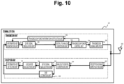
Fig. 10 is a block diagram for explaining a configuration of a reception device in the first embodiment of the present disclosure. -
Fig. 11 is a diagram for explaining a method in which the reception device calculates a likelihood for a reception point in the first embodiment of the present disclosure. -
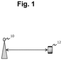
Fig. 1 illustrates an overall configuration of a wireless communication system of a first embodiment of the present disclosure. As illustrated inFig. 1 , the wireless communication system of the present embodiment includes atransmission device 10 and areception device 12. Thetransmission device 10 includes, for example, a base station for mobile communication operated by a communication company, an access point of WiFi (registered trademark), or the like. In addition, thereception device 12 includes a terminal station such as a smartphone or a tablet terminal. -
Fig. 2 is a block diagram for explaining a configuration of atransmission device 14 to be compared with thetransmission device 10 in the present embodiment. Thetransmission device 14 of a comparative example includes an informationbit generation unit 16. The information bitgeneration unit 16 generates information bits to be transmitted to thereception device 12. The information bitgeneration unit 16 may have an error correction coding function or an interleaving function. - The information bits generated by the information
bit generation unit 16 are provided to a datasignal modulation unit 18. The data signalmodulation unit 18 modulates the provided information bits into a data signal. As a modulation scheme, for example, a modulation scheme is considered that can be used for a single-carrier multi-value modulation scheme such as quadrature amplitude modulation (QAM) or APSK. - The data signal generated by the data signal
modulation unit 18 is provided to a digital-to-analog conversion unit 20. The digital-to-analog conversion unit 20 converts the digitally-modulated data signal into an analog transmission signal. - The transmission signal generated by the digital-to-
analog conversion unit 20 is provided to atransmission signal amplifier 22. Thetransmission signal amplifier 22 amplifies the transmission signal and provides the amplified signal to anantenna 24. Then, the transmission signal is transmitted from theantenna 24 toward thereception device 12 in a form of a wireless signal. -
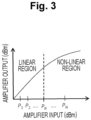
Fig. 3 illustrates an input-output characteristic of thetransmission signal amplifier 22. As illustrated inFig. 3 , in a region where input power (horizontal axis) is smaller than PB, output power (vertical axis) of thetransmission signal amplifier 22 is proportional to the input power. Then, in a region where the input power exceeds PB, a proportional relationship between them collapses. Hereinafter, a region where they have the proportional relationship is referred to as a "linear region", and a region where the proportional relationship between them collapses is referred to as a "non-linear region". -
Fig. 4 illustrates a state in which distortion occurs in a constellation of 8 × 8 = 64 QAM with an increase in transmission power. In the modulation scheme of 64 QAM, 64 symbols arranged in a lattice pattern are defined by changing and adjusting amplitudes of two carrier waves independent of each other. Hereinafter, a point on constellation coordinates at which each of the 64 symbols is defined is referred to as a "signal point". In addition, a point on the constellation coordinates of each data signal to be actually transmitted is referred to as a "reception point". - In the linear region of the
transmission signal amplifier 22, as illustrated on the left side (transmission power P1) ofFig. 4 , reception points form a constellation without distortion. On the other hand, in the non-linear region of thetransmission signal amplifier 22, as illustrated on the right side (transmission power PN) ofFig. 4 , distortion is superimposed on the constellation of the reception points. - The
reception device 12 performs likelihood calculation with signal points existing in the vicinity for each of the reception points included in the transmission signal, and recognizes each of the reception points as any of the 64 symbols on the basis of a result of calculation. Note that the calculation of a likelihood can be executed by, for example, a method described in the following literature. - On the Optimality of Bit Detection of Certain Digital Modulations, Marvin K. Simon and Ramesh Annavajjala, p299-307, IEEE TRANSACTIONS ON COMMUNICATIONS, VOL. 53, NO. 2, FEBRUARY 2005
- If the
reception device 12 performs the above likelihood calculation by using the signal points constituting the constellation without distortion, reception points generated in the linear region can be correctly recognized. However, since reception points generated in the non-linear region deviates from original positions on the constellation, the reception points cannot be correctly recognized. For this reason, when thetransmission signal amplifier 22 uses the non-linear region, a situation may occur in which data is erroneously recognized in thereception device 12. - In the
transmission device 14 of the comparative example, if the transmission power is limited to the linear region of thetransmission signal amplifier 22, it is possible to prevent distortion from occurring in the constellation of the reception points. Thus, by applying such a limitation, it is possible to prevent erroneous recognition of data in thereception device 12. However, in that case, a situation occurs in which an amplification capability of thetransmission signal amplifier 22 cannot be sufficiently utilized. - Thus, in the present embodiment, the
transmission device 10 is caused to execute transmission power control by the following procedure. - 1. Prediction of distortion caused in the constellation is performed on the basis of set transmission power.
- 2. On the basis of a result of the prediction, a symbol error rate SER or a bit error rate BER occurring in the
reception device 12 is predicted. - 3. The transmission power is adjusted so that SER or BER satisfies a requirement.
- According to the above processing, the transmission power of the
transmission device 10 is appropriately controlled so that SER or BER clears a desired value. Therefore, according to the present embodiment, it is possible to efficiently obtain good communication quality by effectively utilizing the capability of thetransmission signal amplifier 22. Hereinafter, the above features will be described in more detail. -
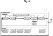
Fig. 5 is a block diagram for explaining a configuration of thetransmission device 10 in the present embodiment. Note that, inFig. 5 , the same elements as those included in thetransmission device 14 of the comparative example (seeFig. 2 ) are denoted by the same reference signs, and description thereof will be omitted or simplified. - The
transmission device 10 in the present embodiment includes a transmission unit illustrated in the upper part ofFig. 5 . Here, the informationbit generation unit 16 in thetransmission device 14 of the comparative example is replaced with an informationbit generation unit 26. The information bitgeneration unit 26 included in the present embodiment generates information bits regarding a specification of thetransmission device 10 at a stage where communication between thetransmission device 10 and thereception device 12 is started. Specifically, a modulation scheme used by thetransmission device 10 and the input-output characteristic of the transmission signal amplifier 22 (seeFig. 3 ) are converted into information bits. - The information bits generated in this manner are transmitted from the
transmission device 10 to thereception device 12 at the stage where communication between thetransmission device 10 and thereception device 12 is started. For this reason, in the present embodiment, the modulation scheme used by thetransmission device 10 and the input-output characteristic of thetransmission signal amplifier 22 are shared between both devices when communication between both devices is started. - The
transmission device 10 in the present embodiment includes a transmissionpower control unit 28 at a preceding stage of thetransmission signal amplifier 22. The transmissionpower control unit 28 controls the transmission power used by thetransmission signal amplifier 22 to obtain desired communication quality. A control command of the transmissionpower control unit 28 is provided to thetransmission signal amplifier 22 and is provided to a transmission powerinformation notification unit 30. - The transmission power
information notification unit 30 provides a command value of the transmission power to the informationbit generation unit 26. Then, the informationbit generation unit 26 generates bit information regarding current transmission power and includes the information in transmission data. As a result, from thetransmission device 10 of the present embodiment, with transmission power set by the transmissionpower control unit 28, a transmission signal including information on the transmission power is transmitted toward thereception device 12. - The transmission unit of the
transmission device 10 further includes an error ratecharacteristic estimation unit 32. The error ratecharacteristic estimation unit 32 has a function of estimating a probability that a signal transmitted from thetransmission device 10 is erroneously recognized in thereception device 12. The function related to the error ratecharacteristic estimation unit 32 will be described in detail later with reference toFigs. 6 to 8 . - The
transmission device 10 includes a reception unit illustrated in the lower part ofFig. 5 . The reception unit includes a receptionsignal amplification unit 34 that receives supply of a reception signal from theantenna 24. The receptionsignal amplification unit 34 amplifies a received signal with an appropriate gain and provides the amplified signal to an analog-to-digital conversion unit 36. - The analog-to-
digital conversion unit 36 is a block for demodulating a reception signal in an analog form into a digital signal. The signal digitized by the analog-to-digital conversion unit 36 is provided to a datasignal equalization unit 38. - The data signal
equalization unit 38 is a block that performs inverse calculation on information on an amplitude and a phase of a communication path response to obtain an estimated value of the transmission signal. A training signal is exchanged between thetransmission device 10 and thereception device 12 prior to the data signal. Content of the training signal is shared in advance between thetransmission device 10 and thereception device 12. For this reason, thetransmission device 10 can detect an influence caused by a communication path on the basis of the actually received training signal. Specifically, the data signalequalization unit 38 generates a data signal in which the influence caused by the communication path is offset by reflecting a result of the training in the data signal received from thereception device 12. - The data signal generated by the data signal
equalization unit 38 is provided to alikelihood calculation unit 40. Thelikelihood calculation unit 40 calculates likelihood for signal points on a constellation stored in thelikelihood calculation unit 40 itself for a reception point indicated by the data signal. Then, a signal point at which the highest likelihood is obtained is recognized as a symbol intended by the reception point of this time. - A signal symbolized by the
likelihood calculation unit 40 is provided to an informationbit detection unit 42. The informationbit detection unit 42 detects received bits from the symbolized signal. In addition, the informationbit detection unit 42 may have an error correction decoding function or an interleaving function as necessary in accordance with the informationbit generation unit 26. - As described above, the
transmission device 10 of the present embodiment includes the error ratecharacteristic estimation unit 32. In a field of wireless communication, the symbol error rate SER or the bit error rate BER may be used as an index of communication quality. The error ratecharacteristic estimation unit 32 calculates SER or BER depending on content required as an evaluation index by a method described below, and provides a result of calculation to the transmissionpower control unit 28. Then, the transmissionpower control unit 28 sets the transmission power of thetransmission device 10 so that SER or BER falls within a requirement threshold. -
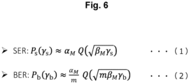
Fig. 6 illustrates an arithmetic expression (1) of the symbol error rate SER and an arithmetic expression (2) of the bit error rate BER. In these arithmetic expressions, "M" is the number of signal points constituting the constellation, and "m" is the number of bits of each signal point. For example, in the case of 64 QAM, the numbers are M = 64 and m = log2M = 6. - As shown in the expression (1), SER = Ps is a function of "γs". In addition, as shown in the expression (2), BER = Pb is a function of "γb". An SNR for each symbol is represented by γs, and an SNR for each bit is represented by γb. Note that a relationship of γs = mγb is established between γs and γb.
- SER = Ps(γs) can be approximately obtained by αMQ(√(βMγs)) using a Q function. BER = Pb(γb) can be approximately obtained by (αM/m)Q(√(mβMγb)). In the expressions (1) and (2), "αM" is the number of nearest points in the constellation. A value of the number is determined depending on the number of signal points included in the constellation, in other words, depending on the modulation scheme. For example, αM = 2 is obtained in the case of QPSK, and αM = 4 is obtained in the case of 16 QAM.
-
Fig. 7 illustrates a constellation of 16 QAM. In this case, a constellation is configured having four points in each quadrant, a total of M = 16 signal points. In this case, if a signal point indicated by o in the figure is an attention point, as indicated by △ around the attention point, the number of nearest points "αM" is four. -
Fig. 7 also illustrates "βM". As illustrated in this figure, βM is a coefficient proportional to a minimum Euclidean distance in the constellation. That is, the expressions (1) and (2) illustrated inFig. 6 indicate that the error rate (SER, BER) is determined when the constellation (αM, βM, m) and the SNR (γs, γb) are determined. -
Fig. 8 is a diagram for explaining a concept of a minimum Euclidean distance in a constellation with distortion. When thetransmission signal amplifier 22 uses the non-linear region, a signal point distance is compressed in a peripheral portion of the constellation as illustrated inFig. 8 . For example, a Euclidean distance between asignal point 44 and asignal point 46 illustrated inFig. 8 is sufficiently shorter than a Euclidean distance between signal points existing near the center of the constellation. For this reason, in a case where the constellation with distortion is used, it is necessary to extract a minimum Euclidean distance from the constellation and calculate SER or BER by using βM and the like corresponding to an extracted value of the minimum Euclidean distance. - In the present embodiment, if the transmission power is determined, the
transmission device 10 can estimate a constellation formed by a signal to be actually transmitted regardless of whether the transmission power is in the linear region or the non-linear region. If the actually formed constellation is known, αM and βM achieved therein are known. Further, thetransmission device 10 can acquire information on the SNR from thereception device 12. Then, thetransmission device 10 can estimate SER and BER predicted to occur in thereception device 12 by applying these pieces of information to the expression (1) or (2). -
Fig. 9 is a flowchart for explaining a flow of processing executed by thetransmission device 10 to calculate the error rates (SER, BER) in accordance with the above principle and control the transmission power in accordance with a result of calculation. Note that a routine illustrated inFig. 9 is repeatedly activated at predetermined time intervals after communication is established between thetransmission device 10 and thereception device 12. - In the routine illustrated in
Fig. 9 , first, an initial value of the transmission power used in thetransmission signal amplifier 22 is set (step 100). When the processing ofstep 100 ends, thetransmission device 10 emits a transmission signal with the set transmission power. - When receiving the signal from the
transmission device 10, thereception device 12 calculates an SNR (γs, γb) on the basis of strength of the signal. Then, the calculated SNR is returned to thetransmission device 10. Thetransmission device 10 acquires the SNR returned in this manner (step 102). - Next, the
transmission device 10 calculates SER and BER that will be achieved under the current transmission power (step 104). Specifically, a constellation corresponding to the current transmission power is read, and αM and βM corresponding to the constellation are determined. Then, SER and BER are calculated by the expression (1) or (2) on the basis of the number of bits m unique to the modulation scheme, the SNR (γs, γb) acquired from thereception device 12, and αM and βM described above. - Next, it is determined whether or not the obtained error rate (SER, BER) clears a system requirement. That is, in a case where the wireless communication system uses SER as the evaluation index, it is determined whether SER is less than or equal to the requirement threshold. In addition, in a case where the wireless communication system uses BER as the evaluation index, it is determined whether BER is less than or equal to the requirement threshold.
- As a result, in a case where it is determined that the error rate (SER, BER) clears the requirement, it can be determined that the current transmission power is appropriate. In this case, the routine of this time is ended in a state where the transmission power is maintained as power for communication.
- On the other hand, in a case where it is determined in
step 106 that the current error rate does not clear the requirement, it is determined whether or not search for all transmission powers possible is ended (step 108). For example, in a case where the transmission power is switchable in N levels, it is determined whether the processing ofstep 102 to 106 has been executed for all of the N levels. - As a result, in a case where it is determined that the search is ended for all the transmission powers, this routine is temporarily ended, and the processing of
step 100 and subsequent steps is started again. On the other hand, in a case where it is determined that the search for all the transmission power is not ended, the transmission power is changed in accordance with a predetermined rule (step 110). Thereafter, the processing ofstep 102 and subsequent steps is repeated. - When the transmission power changes, the SNR in the
reception device 12 changes, and magnitude of distortion superimposed on the constellation changes. According to the routine illustrated inFig. 9 , it is possible to find the transmission power at which the error rate (SER, BER) can clear the requirement. In other words, according to the present embodiment, as long as the error rate can be cleared, use of the transmission power belonging to the non-linear region can also be allowed. Therefore, according to the present embodiment, it is possible to efficiently achieve excellent communication quality by effectively utilizing the capability of thetransmission signal amplifier 22 within a range in which erroneous recognition of data does not occur. -
Fig. 10 is a block diagram for explaining a configuration of thereception device 12 in the present embodiment. Thereception device 12 includes elements that function substantially similarly to the elements included in thetransmission device 10 in many parts. - Specifically, a transmission unit of the
reception device 12 has a configuration for functioning substantially similarly to the transmission unit of thetransmission device 10. In addition, a reception unit of thereception device 12 has a configuration for functioning substantially similarly to the reception unit of thetransmission device 10 except for anSNR estimation unit 68 and alikelihood calculation unit 70. Here, description of substantially common functions will be omitted, and feature points of thereception device 12 will be described in detail. - The
SNR estimation unit 68 calculates an SNR of the signal received from thetransmission device 10. The SNR estimated by theSNR estimation unit 68 is provided to an informationbit generation unit 48 and then transmitted from the transmission unit of thereception device 12 to thetransmission device 10. - The
likelihood calculation unit 70 calculates a likelihood for a reception point on the basis of the transmission power used in thetransmission device 10. -
Fig. 11 is a diagram for explaining a function of thelikelihood calculation unit 70. The left side ofFig. 11 illustrates an outline of likelihood calculation of a case where thetransmission device 10 uses the transmission power P1. In this case, the constellation of the reception signal has no distortion in which signal points 74 are correctly arranged in a lattice pattern. Thelikelihood calculation unit 70 refers to the constellation, and calculates, for some of the signal points 74 located in the vicinity of thereception point 76, a likelihood by using a normal distribution for a Euclidean distance between thereception point 76 and eachsignal point 74. Then, thesignal point 74 at which the maximum likelihood is obtained is adopted as a symbol corresponding to thereception point 76. - The right side of
Fig. 11 illustrates an outline of likelihood calculation of a case where thetransmission device 10 uses the transmission power PN. In this case, the constellation of the reception signal includes a deviation caused by the nonlinearity of thetransmission signal amplifier 22 at each of the signal points 74. In this case, thelikelihood calculation unit 70 calculates a likelihood for thereception point 76 by a method similar to the above by referring to the constellation with the deviation. Then, on the basis of a result of calculation, the symbol meant by thereception point 76 is specified. - As described above, in the present embodiment, the modulation scheme and the input-output characteristic of the
transmission signal amplifier 22 are shared between thetransmission device 10 and thereception device 12. In addition, thetransmission device 10 successively provides information on the transmission power used for communication to thereception device 12. Then, as described with reference toFig. 11 , thereception device 12 performs likelihood calculation on the basis of the constellation reproduced depending on the transmission power. - As described above, in the present embodiment, the
transmission device 10 is allowed to use the non-linear region of thetransmission signal amplifier 22. Moreover, thetransmission device 10 controls the transmission power so that the error rate (SER, BER) clears the requirement. Therefore, according to the present embodiment, it is possible to reliably avoid occurrence of an excessive error rate due to use of excessive transmission power. - Further, in the present embodiment, in a case where distortion occurs in the constellation, the
reception device 12 performs likelihood calculation on the assumption of the distortion. Therefore, according to the present embodiment, in a case where thetransmission device 10 uses the transmission power determined to be usable on the basis of the error rate (SER, BER), it is possible to effectively avoid occurrence of a situation in which data is erroneously recognized on responsibility of thereception device 12 side. - By the way, in the first embodiment described above, the search for the transmission power is ended when the transmission power at which the error rate (SER, BER) clears a desired requirement is found. However, the present disclosure is not limited thereto. For example, the search may be continued even after a condition that the error rate clears the requirement is found, and the transmission power with the smallest error rate may be found.
- In addition, in the first embodiment described above, the
transmission device 10 provides the specification of thetransmission signal amplifier 22 to thereception device 12 at the start of wireless communication. However, the present disclosure is not limited thereto. For example, thetransmission device 10 may be caused to store thereception device 12 to which the specification is provided, and thereception device 12 to which the specification is provided may be caused to store information on the specification. Then, transmission and reception of the above specification may be omitted for the second and subsequent communications between thebase station 20 and theterminal station 22. - In addition, in the first embodiment described above, the
transmission device 10 provides, to thereception device 12, information on the modulation scheme used for the wireless communication together with the specification of thetransmission signal amplifier 22. However, the present disclosure is not limited thereto. For example, in a case where the modulation scheme used for communication between thetransmission device 10 and thereception device 12 is determined in advance, provision of information on the modulation scheme can be omitted. -
- 10
- Transmission device
- 12
- Reception device
- 22
- Transmission signal amplifier
- 26
- Information bit generation unit
- 28
- Transmission power control unit
- 30
- Transmission power information notification unit
- 32
- Error rate characteristic estimation unit
- 68
- SNR estimation unit
- 70
- Likelihood calculation unit
Claims (8)
- A wireless communication system comprising a transmission device and a reception device that perform wireless communication by using a single-carrier multi-value modulation scheme, wherein
the transmission device includes:a transmission signal amplifier enabled to vary transmission power;a transmission power control unit that controls transmission power used by the transmission signal amplifier;an error rate characteristic estimation unit that estimates an error rate of a reception signal in the reception device; anda reception unit that receives information on an SNR in the reception device,the error rate characteristic estimation unit is configured to execute:processing of estimating a constellation corresponding to the modulation scheme and reflecting a specification regarding an input-output characteristic of the transmission signal amplifier on a basis of the transmission power; andprocessing of estimating the error rate on a basis of a characteristic of the constellation and the SNR, andthe transmission power control unit is configured to execute transmission power control processing of controlling the transmission power such that the error rate satisfies a predetermined requirement. - The wireless communication system according to claim 1, wherein
the transmission device is configured to execute:processing of providing the specification to the reception device; andprocessing of providing information on transmission power used by the transmission signal amplifier to the reception device,the reception device includes:an SNR estimation unit that estimates the SNR on a basis of a data signal received;a likelihood calculation unit that calculates a likelihood for the data signal; andan information bit detection unit that detects information bits from the data signal on a basis of a calculation result of the likelihood, andthe likelihood calculation unit is configured to executes:processing of estimating a constellation corresponding to the transmission power on a basis of the specification and the transmission power provided from the transmission device; andprocessing of calculating likelihood for signal points included in the constellation, for the data signal. - The wireless communication system according to claim 1 or 2, whereinthe error rate characteristic estimation unit is configured to estimate the error rate corresponding to transmission power every time the transmission power is set,the transmission power control processing includes:processing of setting an initial value for transmission power;processing of determining whether or not the error rate corresponding to transmission power used by the transmission signal amplifier satisfies the requirement;processing of maintaining the transmission power as being used for communication in a case where it is determined that the error rate satisfies the requirement; andprocessing of setting the transmission power to a new value in a case where it is determined that the error rate does not satisfy the requirement.
- The wireless communication system according to claim 1 or 2, whereinthe error rate characteristic estimation unit is configured to estimate the error rate corresponding to transmission power every time the transmission power is set, andthe transmission power control processing includes:processing of sequentially setting the transmission power to new values in an entire range possible for the transmission signal amplifier; andprocessing of selecting transmission power indicating a best error rate as being used for communication when search is ended for the entire range.
- A wireless communication method using a transmission device and a reception device that perform wireless communication by using a single-carrier multi-value modulation scheme,the transmission device including a transmission signal amplifier enabled to vary transmission power,the wireless communication method comprising:a step, by the transmission device, of estimating a constellation corresponding to the modulation scheme and reflecting a specification regarding an input-output characteristic of the transmission signal amplifier on a basis of the transmission power;a step, by the transmission device, of receiving information on an SNR in the reception device;a step, by the transmission device, of estimating an error rate of a reception signal in the reception device on a basis of a characteristic of the constellation and the SNR; anda step, by the transmission device, of controlling the transmission power such that the error rate satisfies a predetermined requirement.
- The wireless communication method according to claim 5, further comprising:a step, by the transmission device, of providing the specification to the reception device;a step, by the transmission device, of providing information on transmission power used by the transmission signal amplifier to the reception device;a step, by the reception device, of estimating a constellation corresponding to the transmission power on a basis of the specification and the transmission power;a step, by the reception device, of calculating likelihood for signal points included in the constellation, for a data signal received; anda step, by the reception device, of detecting information bits from the data signal on a basis of a calculation result of the likelihood.
- The wireless communication method according to claim 5 or 6, further comprising:a step, by the transmission device, of estimating the error rate corresponding to transmission power every time the transmission power is set;a step, by the transmission device, of setting an initial value for transmission power;a step, by the transmission device, of determining whether or not the error rate corresponding to transmission power used by the transmission signal amplifier satisfies the requirement;a step, by the transmission device, of maintaining the transmission power as being used for communication in a case where it is determined that the error rate satisfies the requirement; anda step, by the transmission device, of setting the transmission power to a new value in a case where it is determined that the error rate does not satisfy the requirement.
- A wireless communication transmission device that performs wireless communication by using a single-carrier multi-value modulation scheme, the wireless communication transmission device comprising:a transmission signal amplifier enabled to vary transmission power;a transmission power control unit that controls transmission power used by the transmission signal amplifier;an error rate characteristic estimation unit that estimates an error rate of a reception signal in a reception device of a communication partner; anda reception unit that receives information on an SNR in the reception device, whereinthe error rate characteristic estimation unit is configured to execute:processing of estimating a constellation corresponding to the modulation scheme and reflecting a specification regarding an input-output characteristic of the transmission signal amplifier on a basis of the transmission power; andprocessing of estimating the error rate on a basis of a characteristic of the constellation and the SNR, andthe transmission power control unit is configured to execute processing of controlling the transmission power such that the error rate satisfies a predetermined requirement.
Applications Claiming Priority (1)
| Application Number | Priority Date | Filing Date | Title |
|---|---|---|---|
| PCT/JP2021/032465 WO2023032160A1 (en) | 2021-09-03 | 2021-09-03 | Wireless communication system, wireless communication method, and wireless communication transmission device |
Publications (2)
| Publication Number | Publication Date |
|---|---|
| EP4398528A1 true EP4398528A1 (en) | 2024-07-10 |
| EP4398528A4 EP4398528A4 (en) | 2025-06-25 |
Family
ID=85412342
Family Applications (1)
| Application Number | Title | Priority Date | Filing Date |
|---|---|---|---|
| EP21956048.9A Pending EP4398528A4 (en) | 2021-09-03 | 2021-09-03 | Wireless communication system, wireless communication method, and wireless communication transmission device |
Country Status (4)
| Country | Link |
|---|---|
| US (1) | US20250097851A1 (en) |
| EP (1) | EP4398528A4 (en) |
| JP (1) | JP7563615B2 (en) |
| WO (1) | WO2023032160A1 (en) |
Families Citing this family (1)
| Publication number | Priority date | Publication date | Assignee | Title |
|---|---|---|---|---|
| WO2023162104A1 (en) * | 2022-02-24 | 2023-08-31 | 日本電信電話株式会社 | Radio wave direction-of-arrival estimation device and radio wave direction-of-arrival estimation method |
Family Cites Families (14)
| Publication number | Priority date | Publication date | Assignee | Title |
|---|---|---|---|---|
| JPH11196456A (en) * | 1998-01-05 | 1999-07-21 | Oki Electric Ind Co Ltd | Transmission power controller |
| JP2003046436A (en) * | 2001-07-30 | 2003-02-14 | Nec Corp | Transmission power control system, and its transmission power control method |
| EP1971046A4 (en) * | 2005-12-27 | 2012-03-07 | Fujitsu Ltd | TRANSMISSION CONTROL METHOD IN WIRELESS COMMUNICATION SYSTEM AND RECEIVER USED IN THE SAME SYSTEM |
| US8355466B2 (en) * | 2009-09-25 | 2013-01-15 | General Dynamics C4 Systems, Inc. | Cancelling non-linear power amplifier induced distortion from a received signal by moving incorrectly estimated constellation points |
| US8571497B1 (en) * | 2010-11-19 | 2013-10-29 | Marvell International Ltd. | Closed-loop power control in conjunction with adaptive power amplifier linearization |
| TWI540888B (en) * | 2014-06-04 | 2016-07-01 | 國立中山大學 | Power allocation method for scalable video transmissions over mimo systems |
| JP6577800B2 (en) * | 2015-09-14 | 2019-09-18 | 日本放送協会 | Single carrier transmission device and reception device |
| US9807571B1 (en) * | 2016-08-12 | 2017-10-31 | Rockwell Collins, Inc. | High rate VHF datalink |
| CN114584272B (en) * | 2016-12-12 | 2024-04-09 | 索尼公司 | Communication device and method for communicating with corresponding communication device |
| JP6924606B2 (en) * | 2017-04-21 | 2021-08-25 | 日本放送協会 | Single carrier type transmitter |
| JP7159718B2 (en) * | 2018-09-10 | 2022-10-25 | 日本電信電話株式会社 | Optical/RF wireless hybrid communication system and control method |
| JP6879333B2 (en) * | 2019-05-29 | 2021-06-02 | 沖電気工業株式会社 | Modulation device, demodulation device, modulation method, demodulation method and transmission device |
| US12388701B2 (en) * | 2021-08-19 | 2025-08-12 | Nippon Telegraph And Telephone Corporation | Wireless communication system, wireless communication method, and reception apparatus |
| CN117459179A (en) * | 2022-07-19 | 2024-01-26 | 华为技术有限公司 | A communication method and device |
-
2021
- 2021-09-03 EP EP21956048.9A patent/EP4398528A4/en active Pending
- 2021-09-03 JP JP2023544941A patent/JP7563615B2/en active Active
- 2021-09-03 WO PCT/JP2021/032465 patent/WO2023032160A1/en not_active Ceased
- 2021-09-03 US US18/294,197 patent/US20250097851A1/en active Pending
Also Published As
| Publication number | Publication date |
|---|---|
| EP4398528A4 (en) | 2025-06-25 |
| WO2023032160A1 (en) | 2023-03-09 |
| JPWO2023032160A1 (en) | 2023-03-09 |
| JP7563615B2 (en) | 2024-10-08 |
| US20250097851A1 (en) | 2025-03-20 |
Similar Documents
| Publication | Publication Date | Title |
|---|---|---|
| US7630692B2 (en) | Information processing apparatus and communication apparatus | |
| US12388701B2 (en) | Wireless communication system, wireless communication method, and reception apparatus | |
| EP4398533B1 (en) | Wireless communication system, wireless communication method, and wireless communication transmission device | |
| US7890839B2 (en) | Radio communication apparatus suppressing correction error while maintaining communication quality, and method and program for error correction | |
| US11677597B2 (en) | Wireless communication device, wireless communication system, and wireless communication method | |
| US20250097851A1 (en) | Wireless communication system, wireless communication method, and wireless communication transmission device | |
| KR20110068377A (en) | Method and apparatus for generating soft decision information based on non-Gaussian channel in wireless communication system | |
| US12457144B2 (en) | Wireless communication system, wireless communication method, centralized control device, and wireless communication program | |
| KR101704096B1 (en) | Process for performing log-likelihood-ratio clipping in a soft-decision near-ml detector, and detector for doing the same | |
| EP3425807B1 (en) | Wireless communication system and communication method | |
| KR102715743B1 (en) | Method for determining step size of uniform quantization method in relay and amplify-quantize forward relay system supporting the same | |
| US12489660B2 (en) | Wireless communication system, wireless communication method, and receiver | |
| WO2023157132A1 (en) | Wireless communication method, wireless communication system, and transmission device | |
| WO2023157133A1 (en) | Wireless communication method, wireless communication system, and transmission device | |
| JPWO2011078097A1 (en) | Compound condition judging unit, transmission device, compound condition judging method | |
| JP2005341405A (en) | Communication method and wireless device using communication method | |
| JP5472448B2 (en) | COMMUNICATION DEVICE, COMMUNICATION SYSTEM, AND COMMUNICATION CONTROL METHOD | |
| US20250119328A1 (en) | Wireless communication method, wireless communication system, and wireless transmission device | |
| WO2025160693A1 (en) | Method and apparatus for modulation | |
| JP4610248B2 (en) | Diversity method and receiving apparatus using the same | |
| WO2024171448A1 (en) | Wireless communication system, reception device, wireless communication method, and reception program | |
| WO2024171447A1 (en) | Wireless communication system, reception device, wireless communication method, and reception program | |
| KR20240103660A (en) | An wireless communication device and an operating method thereof | |
| JP2015139190A (en) | Radio communication device, radio communication system, and radio communication method | |
| JP2007096382A (en) | Wireless communication system, transmitter and receiver thereof |
Legal Events
| Date | Code | Title | Description |
|---|---|---|---|
| STAA | Information on the status of an ep patent application or granted ep patent |
Free format text: STATUS: THE INTERNATIONAL PUBLICATION HAS BEEN MADE |
|
| PUAI | Public reference made under article 153(3) epc to a published international application that has entered the european phase |
Free format text: ORIGINAL CODE: 0009012 |
|
| STAA | Information on the status of an ep patent application or granted ep patent |
Free format text: STATUS: REQUEST FOR EXAMINATION WAS MADE |
|
| 17P | Request for examination filed |
Effective date: 20240207 |
|
| AK | Designated contracting states |
Kind code of ref document: A1 Designated state(s): AL AT BE BG CH CY CZ DE DK EE ES FI FR GB GR HR HU IE IS IT LI LT LU LV MC MK MT NL NO PL PT RO RS SE SI SK SM TR |
|
| DAV | Request for validation of the european patent (deleted) | ||
| DAX | Request for extension of the european patent (deleted) | ||
| A4 | Supplementary search report drawn up and despatched |
Effective date: 20250526 |
|
| RIC1 | Information provided on ipc code assigned before grant |
Ipc: H04W 52/52 20090101ALI20250521BHEP Ipc: H04W 52/24 20090101ALI20250521BHEP Ipc: H04W 52/20 20090101ALI20250521BHEP Ipc: H04L 27/20 20060101AFI20250521BHEP |
|
| RAP3 | Party data changed (applicant data changed or rights of an application transferred) |
Owner name: NTT, INC. |
|
| STAA | Information on the status of an ep patent application or granted ep patent |
Free format text: STATUS: EXAMINATION IS IN PROGRESS |
|
| 17Q | First examination report despatched |
Effective date: 20251204 |