EP4398489A2 - Verfahren und vorrichtung zur konstruktion von polaren codes - Google Patents
Verfahren und vorrichtung zur konstruktion von polaren codes Download PDFInfo
- Publication number
- EP4398489A2 EP4398489A2 EP24178153.3A EP24178153A EP4398489A2 EP 4398489 A2 EP4398489 A2 EP 4398489A2 EP 24178153 A EP24178153 A EP 24178153A EP 4398489 A2 EP4398489 A2 EP 4398489A2
- Authority
- EP
- European Patent Office
- Prior art keywords
- block size
- determining
- control data
- information
- parameters
- Prior art date
- Legal status (The legal status is an assumption and is not a legal conclusion. Google has not performed a legal analysis and makes no representation as to the accuracy of the status listed.)
- Pending
Links
- 238000000034 method Methods 0.000 title claims abstract description 47
- 241000169170 Boreogadus saida Species 0.000 title description 45
- 238000010276 construction Methods 0.000 claims description 48
- 230000005540 biological transmission Effects 0.000 claims description 21
- 238000013507 mapping Methods 0.000 claims description 5
- 238000004891 communication Methods 0.000 description 40
- 238000012545 processing Methods 0.000 description 25
- 230000015654 memory Effects 0.000 description 22
- 230000006870 function Effects 0.000 description 18
- 239000013598 vector Substances 0.000 description 17
- 238000010586 diagram Methods 0.000 description 15
- 238000005516 engineering process Methods 0.000 description 14
- 230000008901 benefit Effects 0.000 description 7
- 230000008569 process Effects 0.000 description 7
- 230000001413 cellular effect Effects 0.000 description 6
- 238000013461 design Methods 0.000 description 5
- 230000011664 signaling Effects 0.000 description 5
- 230000006835 compression Effects 0.000 description 4
- 238000007906 compression Methods 0.000 description 4
- 125000004122 cyclic group Chemical group 0.000 description 4
- 230000008520 organization Effects 0.000 description 4
- 238000004590 computer program Methods 0.000 description 3
- 238000012937 correction Methods 0.000 description 3
- 238000001514 detection method Methods 0.000 description 3
- 238000007726 management method Methods 0.000 description 3
- 230000003287 optical effect Effects 0.000 description 3
- 238000013468 resource allocation Methods 0.000 description 3
- 230000011218 segmentation Effects 0.000 description 3
- 238000001228 spectrum Methods 0.000 description 3
- 101150071746 Pbsn gene Proteins 0.000 description 2
- 238000003491 array Methods 0.000 description 2
- 230000008859 change Effects 0.000 description 2
- 239000003795 chemical substances by application Substances 0.000 description 2
- 230000006837 decompression Effects 0.000 description 2
- 230000000977 initiatory effect Effects 0.000 description 2
- 230000007774 longterm Effects 0.000 description 2
- 238000010295 mobile communication Methods 0.000 description 2
- 230000010363 phase shift Effects 0.000 description 2
- 239000004984 smart glass Substances 0.000 description 2
- 238000012546 transfer Methods 0.000 description 2
- 239000000654 additive Substances 0.000 description 1
- 230000000996 additive effect Effects 0.000 description 1
- 238000013459 approach Methods 0.000 description 1
- 230000002860 competitive effect Effects 0.000 description 1
- 230000002349 favourable effect Effects 0.000 description 1
- 230000003993 interaction Effects 0.000 description 1
- 238000004519 manufacturing process Methods 0.000 description 1
- 238000012986 modification Methods 0.000 description 1
- 230000004048 modification Effects 0.000 description 1
- 239000005022 packaging material Substances 0.000 description 1
- 230000002093 peripheral effect Effects 0.000 description 1
- 230000010287 polarization Effects 0.000 description 1
- 238000011160 research Methods 0.000 description 1
- 230000003595 spectral effect Effects 0.000 description 1
- 230000001360 synchronised effect Effects 0.000 description 1
- 210000000707 wrist Anatomy 0.000 description 1
Images


Classifications
-
- H—ELECTRICITY
- H03—ELECTRONIC CIRCUITRY
- H03M—CODING; DECODING; CODE CONVERSION IN GENERAL
- H03M13/00—Coding, decoding or code conversion, for error detection or error correction; Coding theory basic assumptions; Coding bounds; Error probability evaluation methods; Channel models; Simulation or testing of codes
- H03M13/03—Error detection or forward error correction by redundancy in data representation, i.e. code words containing more digits than the source words
- H03M13/05—Error detection or forward error correction by redundancy in data representation, i.e. code words containing more digits than the source words using block codes, i.e. a predetermined number of check bits joined to a predetermined number of information bits
- H03M13/13—Linear codes
-
- H—ELECTRICITY
- H03—ELECTRONIC CIRCUITRY
- H03M—CODING; DECODING; CODE CONVERSION IN GENERAL
- H03M13/00—Coding, decoding or code conversion, for error detection or error correction; Coding theory basic assumptions; Coding bounds; Error probability evaluation methods; Channel models; Simulation or testing of codes
- H03M13/35—Unequal or adaptive error protection, e.g. by providing a different level of protection according to significance of source information or by adapting the coding according to the change of transmission channel characteristics
- H03M13/353—Adaptation to the channel
-
- H—ELECTRICITY
- H04—ELECTRIC COMMUNICATION TECHNIQUE
- H04B—TRANSMISSION
- H04B17/00—Monitoring; Testing
- H04B17/30—Monitoring; Testing of propagation channels
- H04B17/309—Measuring or estimating channel quality parameters
- H04B17/336—Signal-to-interference ratio [SIR] or carrier-to-interference ratio [CIR]
-
- H—ELECTRICITY
- H04—ELECTRIC COMMUNICATION TECHNIQUE
- H04L—TRANSMISSION OF DIGITAL INFORMATION, e.g. TELEGRAPHIC COMMUNICATION
- H04L1/00—Arrangements for detecting or preventing errors in the information received
- H04L1/0001—Systems modifying transmission characteristics according to link quality, e.g. power backoff
- H04L1/0002—Systems modifying transmission characteristics according to link quality, e.g. power backoff by adapting the transmission rate
- H04L1/0003—Systems modifying transmission characteristics according to link quality, e.g. power backoff by adapting the transmission rate by switching between different modulation schemes
-
- H—ELECTRICITY
- H04—ELECTRIC COMMUNICATION TECHNIQUE
- H04L—TRANSMISSION OF DIGITAL INFORMATION, e.g. TELEGRAPHIC COMMUNICATION
- H04L1/00—Arrangements for detecting or preventing errors in the information received
- H04L1/0001—Systems modifying transmission characteristics according to link quality, e.g. power backoff
- H04L1/0009—Systems modifying transmission characteristics according to link quality, e.g. power backoff by adapting the channel coding
- H04L1/0013—Rate matching, e.g. puncturing or repetition of code symbols
-
- H—ELECTRICITY
- H04—ELECTRIC COMMUNICATION TECHNIQUE
- H04L—TRANSMISSION OF DIGITAL INFORMATION, e.g. TELEGRAPHIC COMMUNICATION
- H04L1/00—Arrangements for detecting or preventing errors in the information received
- H04L1/12—Arrangements for detecting or preventing errors in the information received by using return channel
- H04L1/16—Arrangements for detecting or preventing errors in the information received by using return channel in which the return channel carries supervisory signals, e.g. repetition request signals
- H04L1/18—Automatic repetition systems, e.g. Van Duuren systems
- H04L1/1812—Hybrid protocols; Hybrid automatic repeat request [HARQ]
Definitions
- Wireless communication systems are widely deployed to provide various telecommunication services such as telephony, video, data, messaging, and broadcasts.
- Typical wireless communication systems may employ multiple-access technologies capable of supporting communication with multiple users by sharing available system resources (e.g., bandwidth, transmit power).
- multiple-access technologies include code division multiple access (CDMA) systems, time division multiple access (TDMA) systems, frequency division multiple access (FDMA) systems, orthogonal frequency division multiple access (OFDMA) systems, single-carrier frequency divisional multiple access (SC-FDMA) systems, and time division synchronous code division multiple access (TD-SCDMA) systems.
- CDMA code division multiple access
- TDMA time division multiple access
- FDMA frequency division multiple access
- OFDMA orthogonal frequency division multiple access
- SC-FDMA single-carrier frequency divisional multiple access
- TD-SCDMA time division synchronous code division multiple access
- Certain aspects of the present disclosure provide a method for constructing a polar code by a transmitter.
- the method generally includes determining at least one set of parameters corresponding to data to be transmitted, and a set of sorting indices corresponding to bits of the data to be transmitted based on the set of parameters, the set of sorting indices indicating a position set of the bits to be transmitted, polar encoding the data based at least on the set of parameters and the set of sorting indices to generate a coded block of the data, and transmitting the coded block of the data.
- the apparatus generally includes at least one processor and a memory coupled to the at least one processor.
- the at least one processor is generally configured to determine at least one set of parameters corresponding to data to be transmitted, and a set of sorting indices corresponding to bits of the data to be transmitted based on the set of parameters, the set of sorting indices indicating a position set of the bits to be transmitted, polar encode the data based at least on the set of parameters and the set of sorting indices to generate a coded block of the data, and transmit the coded block of the data.
- Polar codes are the first codes with an explicit construction to provably achieve the channel capacity for symmetric binary-input discrete memoryless channels.
- the rows of the Hadamard matrices corresponding to the good channels are selected for information bits.
- the bad channels are used for frozen bits with fixed value of zeros.
- density evolution or Gaussian approximation is generally used to determine the bit-error probability of each channel. For example, if N information bits are desired, the best N channels (with low error probability) are selected for information bits while the remaining channels are designated as frozen bits.
- the bit-error probabilities of all the channels are sorted to determine the best and worst channels, and a position of each bit channel is identified by a corresponding sorting index.
- the sorting indices of the bit channels are generally needed in order to construct polar codes.
- position sets for information bits are required indicating different possibilities for positions of the information bits.
- the position sets for information bits may be different even for the same block size with different rates.
- a Binary vector with 0s for positions of frozen bits and 1s for positions of information bits may be used to represent the position set for information bits.
- a very large memory may be needed to store the vector for indication of the positions of information bits.
- Certain aspects of the present disclosure discuss techniques for constructing polar codes including dynamically generating (e.g., "on the fly") vectors or sorting indices indicating position sets of information bits for the construction, instead of storing pre-defined vectors in memory, thus saving memory and leading to a more efficient construction of polar codes for both traffic and control channels.
- processors include microprocessors, microcontrollers, digital signal processors (DSPs), field programmable gate arrays (FPGAs), programmable logic devices (PLDs), state machines, gated logic, discrete hardware circuits, and other suitable hardware configured to perform the various functionality described throughout this disclosure.
- DSPs digital signal processors
- FPGAs field programmable gate arrays
- PLDs programmable logic devices
- state machines gated logic, discrete hardware circuits, and other suitable hardware configured to perform the various functionality described throughout this disclosure.
- One or more processors in the processing system may execute software.
- Software shall be construed broadly to mean instructions, instruction sets, code, code segments, program code, programs, subprograms, software modules, applications, software applications, software packages, firmware, routines, subroutines, objects, executables, threads of execution, procedures, functions, etc., whether referred to as software, firmware, middleware, microcode, hardware description language, or otherwise.
- Disk and disc includes compact disc (CD), laser disc, optical disc, digital versatile disc (DVD), floppy disk and Blu-ray disc where disks usually reproduce data magnetically, while discs reproduce data optically with lasers. Combinations of the above should also be included within the scope of computer-readable media.
- CDMA Code Division Multiple Access
- TDMA Time Division Multiple Access
- FDMA Frequency Division Multiple Access
- OFDMA Orthogonal FDMA
- SC-FDMA Single-Carrier FDMA
- a CDMA network may implement a radio technology such as Universal Terrestrial Radio Access (UTRA), CDMA2000, etc.
- UTRA includes Wideband-CDMA (W-CDMA) and Low Chip Rate (LCR).
- CDMA2000 covers IS-2000, IS-95, and IS-856 standards.
- a TDMA network may implement a radio technology such as Global System for Mobile Communications (GSM).
- GSM Global System for Mobile Communications
- An OFDMA network may implement a radio technology such as Evolved UTRA (E-UTRA), IEEE 802.11, IEEE 802.16, IEEE 802.20, Flash-OFDM ® , etc.
- E-UTRA, E-UTRA, and GSM are part of Universal Mobile Telecommunication System (UMTS).
- LTE Long Term Evolution
- UTRA, E-UTRA, GSM, UMTS, and LTE are described in documents from an organization named "3rd Generation Partnership Project" (3GPP).
- CDMA2000 is described in documents from an organization named "3rd Generation Partnership Project 2" (3GPP2).
- SC-FDMA Single carrier frequency division multiple access
- the SC-FDMA has similar performance and essentially the same overall complexity as those of OFDMA system.
- SC-FDMA signal has lower peak-to-average power ratio (PAPR) because of its inherent single carrier structure.
- PAPR peak-to-average power ratio
- the SC-FDMA has drawn attention, especially in the uplink (UL) communications where lower PAPR greatly benefits the wireless node in terms of transmit power efficiency.
- An access point may comprise, be implemented as, or known as NodeB, Radio Network Controller (“RNC”), eNodeB (eNB), Base Station Controller (“BSC”), Base Transceiver Station (“BTS”), Base Station (“BS”), Transceiver Function (“TF”), Radio Router, Radio Transceiver, Basic Service Set (“BSS”), Extended Service Set (“ESS”), Radio Base Station (“RBS”), or some other terminology.
- RNC Radio Network Controller
- eNB eNodeB
- BSC Base Station Controller
- BTS Base Transceiver Station
- BS Base Station
- Transceiver Function TF
- Radio Router Radio Transceiver
- BSS Basic Service Set
- ESS Extended Service Set
- RBS Radio Base Station
- An access terminal may comprise, be implemented as, or be known as an access terminal, a subscriber station, a subscriber unit, a mobile station, a remote station, a remote terminal, a user terminal, a user agent, a user device, user equipment (UE), a user station, a wireless node, or some other terminology.
- an access terminal may comprise a cellular telephone, a smart phone, a cordless telephone, a Session Initiation Protocol ("SIP”) phone, a wireless local loop (“WLL”) station, a personal digital assistant (“PDA”), a tablet, a netbook, a smartbook, an ultrabook, a handheld device having wireless connection capability, a Station (“STA”), or some other suitable processing device connected to a wireless modem.
- SIP Session Initiation Protocol
- WLL wireless local loop
- PDA personal digital assistant
- tablet a netbook
- smartbook an ultrabook
- a handheld device having wireless connection capability a Station
- STA Station
- a phone e.g., a cellular phone, a smart phone
- a computer e.g., a desktop
- a portable communication device e.g., a portable computing device (e.g., a laptop, a personal data assistant, a tablet, a netbook, a smartbook, an ultrabook)
- wearable device e.g., smart watch, smart glasses, smart bracelet, smart wristband, smart ring, smart clothing, etc.
- medical devices or equipment e.g., biometric sensors/devices
- an entertainment device e.g., music device, video device, satellite radio, gaming device, etc.
- a vehicular component or sensor smart meters/sensors, industrial manufacturing equipment, a global positioning system device, or any other suitable device that is configured to communicate via a wireless or wired medium.
- the node is a wireless node.
- a wireless node may provide, for example, connectivity for or to a network (e.g., a wide area network such as the Internet or a cellular network) via a wired or wireless communication link.
- Some UEs may be considered machine-type communication (MTC) UEs, which may include remote devices, that may communicate with a base station, another remote device, or some other entity.
- MTC machine type communications
- MTC may refer to communication involving at least one remote device on at least one end of the communication and may include forms of data communication which involve one or more entities that do not necessarily need human interaction.
- MTC UEs may include UEs that are capable of MTC communications with MTC servers and/or other MTC devices through Public Land Mobile Networks (PLMN), for example.
- MTC devices include sensors, meters, location tags, monitors, drones, robots/robotic devices, etc.
- MTC UEs, as well as other types of UEs, may be implemented as NB-IoT (narrowband internet of things) devices.
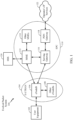
- FIG. 1 is a diagram illustrating an LTE network architecture 100 in which aspects of the present disclosure may be practiced.
- a receiver receives a coded block of data generated by polar encoding.
- the receiver determines at least one set of parameters corresponding to the data, and a set of sorting indices corresponding to bits of the data based on the set of parameters, the set of sorting indices indicating a position set of the bits of the data.
- the receiver then decodes the received coded block of data based at least on the set of parameters and the set of sorting indices to obtain decoded data.
- the LTE network architecture 100 may be referred to as an Evolved Packet System (EPS) 100.
- the EPS 100 may include one or more user equipment (UE) 102, an Evolved UMTS Terrestrial Radio Access Network (E-UTRAN) 104, an Evolved Packet Core (EPC) 110, a Home Subscriber Server (HSS) 120, and an Operator's IP Services 122.
- the EPS can interconnect with other access networks, but for simplicity those entities/interfaces are not shown.
- Exemplary other access networks may include an IP Multimedia Subsystem (IMS) PDN, Internet PDN, Administrative PDN (e.g., Provisioning PDN), carrier-specific PDN, operator-specific PDN, and/or GPS PDN.
- IMS IP Multimedia Subsystem
- IMS IP Multimedia Subsystem
- the EPS provides packet-switched services, however, as those skilled in the art will readily appreciate, the various concepts presented throughout this disclosure may be extended to networks providing circuit-switched services.
- Examples of UEs 102 include a cellular phone, a smart phone, a session initiation protocol (SIP) phone, a laptop, a personal digital assistant (PDA), a satellite radio, a global positioning system, a multimedia device, a video device, a digital audio player (e.g., MP3 player), a camera, a game console, a tablet, a netbook, a smart book, an ultrabook, a drone, a robot, a sensor, a monitor, a meter, a camera/security camera, a gaming device, a wearable device (e.g., smart watch, smart glasses, smart ring, smart bracelet, smart wrist band, smart jewelry, smart clothing, etc.), any other similar functioning device, etc.
- SIP session initiation protocol
- PDA personal digital assistant
- the UE 102 may also be referred to by those skilled in the art as a mobile station, a subscriber station, a mobile unit, a subscriber unit, a wireless unit, a remote unit, a mobile device, a wireless device, a wireless communications device, a remote device, a mobile subscriber station, an access terminal, a mobile terminal, a wireless terminal, a remote terminal, a handset, a user agent, a mobile client, a client, or some other suitable terminology.
- the eNB 106 is connected by an S1 interface to the EPC 110.
- the EPC 110 includes a Mobility Management Entity (MME) 112, other MMEs 114, a Serving Gateway 116, and a Packet Data Network (PDN) Gateway 118.
- MME Mobility Management Entity
- PDN Packet Data Network
- the MME 112 is the control node that processes the signaling between the UE 102 and the EPC 110.
- the MME 112 provides bearer and connection management. All user IP packets are transferred through the Serving Gateway 116, which itself is connected to the PDN Gateway 118.
- the PDN Gateway 118 provides UE IP address allocation as well as other functions.
- the PDN Gateway 118 is connected to the Operator's IP Services 122.
- the Operator's IP Services 122 may include, for example, the Internet, the Intranet, an IP Multimedia Subsystem (IMS), and a PS (packet-switched) Streaming Service (PSS).
- IMS IP Multimedia Subsystem
- PS packet-switched Streaming Service
- the UE102 may be coupled to the PDN through the LTE network.
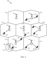
- FIG. 2 is a diagram illustrating an example of an access network 200 in an LTE network architecture in which aspects of the present disclosure may be practiced.
- UEs 206 and eNBs 204 may be configured to implement techniques for efficient construction of polar codes in accordance with aspects of the present discosure.
- the access network 200 is divided into a number of cellular regions (cells) 202.
- One or more lower power class eNBs 208 may have cellular regions 210 that overlap with one or more of the cells 202.
- a lower power class eNB 208 may be referred to as a remote radio head (RRH).
- the lower power class eNB 208 may be a femto cell (e.g., home eNB (HeNB)), pico cell, or micro cell.
- the macro eNBs 204 are each assigned to a respective cell 202 and are configured to provide an access point to the EPC 110 for all the UEs 206 in the cells 202.
- the eNBs 204 are responsible for all radio related functions including radio bearer control, admission control, mobility control, scheduling, security, and connectivity to the serving gateway 116.
- the network 200 may also include one or more relays (not shown). According to one application, a UE may serve as a relay.
- the modulation and multiple access scheme employed by the access network 200 may vary depending on the particular telecommunications standard being deployed.
- OFDM is used on the DL
- SC-FDMA is used on the UL to support both frequency division duplexing (FDD) and time division duplexing (TDD).
- FDD frequency division duplexing
- TDD time division duplexing
- FDD frequency division duplexing
- TDD time division duplexing
- EV-DO Evolution-Data Optimized
- UMB Ultra Mobile Broadband
- EV-DO and UMB are air interface standards promulgated by the 3rd Generation Partnership Project 2 (3GPP2) as part of the CDMA2000 family of standards and employs CDMA to provide broadband Internet access to mobile stations. These concepts may also be extended to Universal Terrestrial Radio Access (UTRA) employing Wideband-CDMA (W-CDMA) and other variants of CDMA, such as TD-SCDMA; Global System for Mobile Communications (GSM) employing TDMA; and Evolved UTRA (E-UTRA), Ultra Mobile Broadband (UNM), IEEE 802.11 (Wi-Fi), IEEE 802.16 (WiMAX), IEEE 802.20, and Flash-OFDM employing OFDMA.
- UTRA Universal Terrestrial Radio Access
- W-CDMA Wideband-CDMA
- GSM Global System for Mobile Communications
- E-UTRA Evolved UTRA
- UMB Ultra Mobile Broadband
- Wi-Fi Wi-Fi
- WiMAX IEEE 802.16
- IEEE 802.20 Flash-OFDM employing OFD
- UTRA, E-UTRA, UMTS, LTE and GSM are described in documents from the 3GPP organization.
- CDMA2000 and UMB are described in documents from the 3GPP2 organization.
- the actual wireless communication standard and the multiple access technology employed will depend on the specific application and the overall design constraints imposed on the system.
- the eNBs 204 may have multiple antennas supporting MIMO technology.
- MIMO technology enables the eNBs 204 to exploit the spatial domain to support spatial multiplexing, beamforming, and transmit diversity.
- Spatial multiplexing may be used to transmit different streams of data simultaneously on the same frequency.
- the data streams may be transmitted to a single UE 206 to increase the data rate or to multiple UEs 206 to increase the overall system capacity. This is achieved by spatially precoding each data stream (e.g., applying a scaling of an amplitude and a phase) and then transmitting each spatially precoded stream through multiple transmit antennas on the DL.
- the spatially precoded data streams arrive at the UE(s) 206 with different spatial signatures, which enables each of the UE(s) 206 to recover the one or more data streams destined for that UE 206.
- each UE 206 transmits a spatially precoded data stream, which enables the eNB 204 to identify the source of each spatially precoded data stream.
- Beamforming may be used to focus the transmission energy in one or more directions. This may be achieved by spatially precoding the data for transmission through multiple antennas. To achieve good coverage at the edges of the cell, a single stream beamforming transmission may be used in combination with transmit diversity.
- FIG. 3 is a diagram 300 illustrating an example of a DL frame structure in LTE.
- a frame (10 ms) may be divided into 10 equally sized sub-frames with indices of 0 through 9. Each sub-frame may include two consecutive time slots.
- a resource grid may be used to represent two time slots, each time slot including a resource block.
- the resource grid is divided into multiple resource elements.
- a resource block contains 12 consecutive subcarriers in the frequency domain and, for a normal cyclic prefix in each OFDM symbol, 7 consecutive OFDM symbols in the time domain, or 84 resource elements.
- For an extended cyclic prefix a resource block contains 6 consecutive OFDM symbols in the time domain and has 72 resource elements.
- R 302, R 304 include DL reference signals (DL-RS).
- the DL-RS include Cell-specific RS (CRS) (also sometimes called common RS) 302 and UE-specific RS (UE-RS) 304.
- CRS Cell-specific RS
- UE-RS 304 are transmitted only on the resource blocks upon which the corresponding physical DL shared channel (PDSCH) is mapped.
- PDSCH physical DL shared channel
- the number of bits carried by each resource element depends on the modulation scheme. Thus, the more resource blocks that a UE receives and the higher the modulation scheme, the higher the data rate for the UE.
- the eNB may send a Physical Control Format Indicator Channel (PCFICH) in the first symbol period of each subframe.
- the PCFICH may convey the number of symbol periods (M) used for control channels, where M may be equal to 1, 2 or 3 and may change from subframe to subframe. M may also be equal to 4 for a small system bandwidth, e.g., with less than 10 resource blocks.
- the eNB may send a Physical HARQ Indicator Channel (PHICH) and a Physical Downlink Control Channel (PDCCH) in the first M symbol periods of each subframe.
- the PHICH may carry information to support hybrid automatic repeat request (HARQ).
- the PDCCH may carry information on resource allocation for UEs and control information for downlink channels.
- the eNB may send a Physical Downlink Shared Channel (PDSCH) in the remaining symbol periods of each subframe.
- the PDSCH may carry data for UEs scheduled for data transmission on the downlink.
- the eNB may send the PSS, SSS, and PBCH in the center 1.08 MHz of the system bandwidth used by the eNB.
- the eNB may send the PCFICH and PHICH across the entire system bandwidth in each symbol period in which these channels are sent.
- the eNB may send the PDCCH to groups of UEs in certain portions of the system bandwidth.
- the eNB may send the PDSCH to specific UEs in specific portions of the system bandwidth.
- the eNB may send the PSS, SSS, PBCH, PCFICH, and PHICH in a broadcast manner to all UEs, may send the PDCCH in a unicast manner to specific UEs, and may also send the PDSCH in a unicast manner to specific UEs.
- Each resource element may cover one subcarrier in one symbol period and may be used to send one modulation symbol, which may be a real or complex value.
- Resource elements not used for a reference signal in each symbol period may be arranged into resource element groups (REGs).
- Each REG may include four resource elements in one symbol period.
- the PCFICH may occupy four REGs, which may be spaced approximately equally across frequency, in symbol period 0.
- the PHICH may occupy three REGs, which may be spread across frequency, in one or more configurable symbol periods. For example, the three REGs for the PHICH may all belong in symbol period 0 or may be spread in symbol periods 0, 1, and 2.
- the PDCCH may occupy 9, 18, 36, or 72 REGs, which may be selected from the available REGs, in the first M symbol periods, for example. Only certain combinations of REGs may be allowed for the PDCCH.
- a subframe may include more than one PDCCH.
- a UE may know the specific REGs used for the PHICH and the PCFICH.
- the UE may search different combinations of REGs for the PDCCH.
- the number of combinations to search is typically less than the number of allowed combinations for the PDCCH.
- An eNB may send the PDCCH to the UE in any of the combinations that the UE will search.
- FIG. 4 is a diagram 400 illustrating an example of an UL frame structure in LTE.
- the available resource blocks for the UL may be partitioned into a data section and a control section.
- the control section may be formed at the two edges of the system bandwidth and may have a configurable size.
- the resource blocks in the control section may be assigned to UEs for transmission of control information.
- the data section may include all resource blocks not included in the control section.
- the UL frame structure results in the data section including contiguous subcarriers, which may allow a single UE to be assigned all of the contiguous subcarriers in the data section.
- a UE may be assigned resource blocks 410a, 410b in the control section to transmit control information to an eNB.
- the UE may also be assigned resource blocks 420a, 420b in the data section to transmit data to the eNB.
- the UE may transmit control information in a physical UL control channel (PUCCH) on the assigned resource blocks in the control section.
- the UE may transmit only data or both data and control information in a physical UL shared channel (PUSCH) on the assigned resource blocks in the data section.
- a UL transmission may span both slots of a subframe and may hop across frequency.
- a set of resource blocks may be used to perform initial system access and achieve UL synchronization in a physical random access channel (PRACH) 430.
- the PRACH 430 carries a random sequence and cannot carry any UL data/signaling.
- Each random access preamble occupies a bandwidth corresponding to six consecutive resource blocks.
- the starting frequency is specified by the network. That is, the transmission of the random access preamble is restricted to certain time and frequency resources. There is no frequency hopping for the PRACH.
- the PRACH attempt is carried in a single subframe (1 ms) or in a sequence of few contiguous subframes and a UE can make only a single PRACH attempt per frame (10 ms).
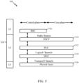
- FIG. 5 is a diagram 500 illustrating an example of a radio protocol architecture for the user and control planes in LTE.
- the radio protocol architecture for the UE and the eNB is shown with three layers: Layer 1, Layer 2, and Layer 3.
- Layer 1 (L1 layer) is the lowest layer and implements various physical layer signal processing functions.
- the L1 layer will be referred to herein as the physical layer 506.
- Layer 2 (L2 layer) 508 is above the physical layer 506 and is responsible for the link between the UE and eNB over the physical layer 506.
- the L2 layer 508 includes a media access control (MAC) sublayer 510, a radio link control (RLC) sublayer 512, and a packet data convergence protocol (PDCP) 514 sublayer, which are terminated at the eNB on the network side.
- MAC media access control
- RLC radio link control
- PDCP packet data convergence protocol
- the UE may have several upper layers above the L2 layer 508 including a network layer (e.g., IP layer) that is terminated at the PDN gateway 118 on the network side, and an application layer that is terminated at the other end of the connection (e.g., far end UE, server, etc.).
- IP layer e.g., IP layer
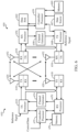
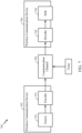
- FIG. 6 is a block diagram of an eNB 610 in communication with a UE 650 in an access network, in which aspects of the present disclosure may be practiced.
- a transmitter determines at least one set of parameters corresponding to data to be transmitted, and a set of sorting indices corresponding to bits of the data to be transmitted based on the set of parameters, the set of sorting indices indicating a position set of the bits to be transmitted.
- the transmitter polar encodes the data based at least on the set of parameters and the set of sorting indices to generate a coded block of the data.
- the transmitter then transmits the coded block of the data.
- upper layer packets from the core network are provided to a controller/processor 675.
- the controller/processor 675 implements the functionality of the L2 layer.
- the controller/processor 675 provides header compression, ciphering, packet segmentation and reordering, multiplexing between logical and transport channels, and radio resource allocations to the UE 650 based on various priority metrics.
- the controller/processor 675 is also responsible for HARQ operations, retransmission of lost packets, and signaling to the UE 650.
- the TX processor 616 implements various signal processing functions for the L1 layer (i.e., physical layer).
- the signal processing functions includes coding and interleaving to facilitate forward error correction (FEC) at the UE 650 and mapping to signal constellations based on various modulation schemes (e.g., binary phase-shift keying (BPSK), quadrature phase-shift keying (QPSK), M-phase-shift keying (M-PSK), M-quadrature amplitude modulation (M-QAM)).
- FEC forward error correction
- BPSK binary phase-shift keying
- QPSK quadrature phase-shift keying
- M-PSK M-phase-shift keying
- M-QAM M-quadrature amplitude modulation
- Each stream is then mapped to an OFDM subcarrier, multiplexed with a reference signal (e.g., pilot) in the time and/or frequency domain, and then combined together using an Inverse Fast Fourier Transform (IFFT) to produce a physical channel carrying a time domain OFDM symbol stream.
- the OFDM stream is spatially precoded to produce multiple spatial streams.
- Channel estimates from a channel estimator 674 may be used to determine the coding and modulation scheme, as well as for spatial processing.
- the channel estimate may be derived from a reference signal and/or channel condition feedback transmitted by the UE 650.
- Each spatial stream is then provided to a different antenna 620 via a separate transmitter 618TX.
- Each transmitter 618TX modulates an RF carrier with a respective spatial stream for transmission.
- each receiver 654RX receives a signal through its respective antenna 652. Each receiver 654RX recovers information modulated onto an RF carrier and provides the information to the receiver (RX) processor 656.
- the RX processor 656 implements various signal processing functions of the L1 layer.
- the RX processor 656 performs spatial processing on the information to recover any spatial streams destined for the UE 650. If multiple spatial streams are destined for the UE 650, they may be combined by the RX processor 656 into a single OFDM symbol stream.
- the RX processor 656 then converts the OFDM symbol stream from the time-domain to the frequency domain using a Fast Fourier Transform (FFT).
- FFT Fast Fourier Transform
- the symbols on each subcarrier, and the reference signal, is recovered and demodulated by determining the most likely signal constellation points transmitted by the eNB 610. These soft decisions may be based on channel estimates computed by the channel estimator 658. The soft decisions are then decoded and deinterleaved to recover the data and control signals that were originally transmitted by the eNB 610 on the physical channel. The data and control signals are then provided to the controller/processor 659.
- a data source 667 is used to provide upper layer packets to the controller/processor 659.
- the data source 667 represents all protocol layers above the L2 layer.
- the controller/processor 659 implements the L2 layer for the user plane and the control plane by providing header compression, ciphering, packet segmentation and reordering, and multiplexing between logical and transport channels based on radio resource allocations by the eNB 610.
- the controller/processor 659 is also responsible for HARQ operations, retransmission of lost packets, and signaling to the eNB 610.
- Channel estimates derived by a channel estimator 658 from a reference signal or feedback transmitted by the eNB 610 may be used by the TX processor 668 to select the appropriate coding and modulation schemes, and to facilitate spatial processing.
- the spatial streams generated by the TX processor 668 are provided to different antenna 652 via separate transmitters 654TX. Each transmitter 654TX modulates an RF carrier with a respective spatial stream for transmission.
- the UL transmission is processed at the eNB 610 in a manner similar to that described in connection with the receiver function at the UE 650.
- Each receiver 618RX receives a signal through its respective antenna 620.
- Each receiver 618RX recovers information modulated onto an RF carrier and provides the information to a RX processor 670.
- the RX processor 670 may implement the L1 layer.
- the controller/processor 675 implements the L2 layer.
- the controller/processor 675 can be associated with a memory 676 that stores program codes and data.
- the memory 676 may be referred to as a computer-readable medium.
- the controller/processor 675 provides demultiplexing between transport and logical channels, packet reassembly, deciphering, header decompression, control signal processing to recover upper layer packets from the UE 650.
- Upper layer packets from the controller/processor 675 may be provided to the core network.
- the controller/processor 675 is also responsible for error detection using an ACK and/or NACK protocol to support HARQ operations.
- the controllers/processors 675, 659 may direct the operations at the eNB 610 and the UE 650, respectively.
- the controller/processor 659 and/or other processors, components and/or modules at the UE 650 and/or the controller/processor 675 and/or other processors, components and/or modules at the eNB 610 may perform or direct operations, for example, operations 900 and 1000 in FIGs 9 and 10 respectively, and/or other processes for the techniques described herein for implementing the efficient construction of polar codes. In certain aspects, one or more of any of the components shown in FIG. 6 may be employed to perform example operations 900 and 1000, and/or other processes for the techniques described herein.
- the memories 660 and 676 may store data and program codes for the UE 650 and eNB 610 respectively, accessible and executable by one or more other components of the UE 650 and the eNB 610.
- FIG. 7 is a schematic illustration 700 of wireless communication between a first wireless communication device 702 and a second wireless communication device 704.
- the first wireless communication device 702 transmits a digital message over a communication channel 706 (e.g., a wireless channel) to the second wireless communication device 704.
- a communication channel 706 e.g., a wireless channel
- One issue in such a scheme that must be addressed to provide for reliable communication of the digital message, is to take into account the noise that affects the communication channel 706.
- Block codes, or error correcting codes are frequently used to provide reliable transmission of digital messages over such noisy channels.
- a typical block code an information message or sequence is split up into blocks, each block having a length of K bits.
- An encoder 724 at the first (transmitting) wireless communication device 102 then mathematically adds redundancy to the information message, resulting in codewords having a length of N , where N > K.
- error correcting block codes are known to those of ordinary skill in the art, including Hamming codes, Bose-Chaudhuri-Hocquenghem (BCH) codes, turbo codes, and low-density parity check (LDPC) codes, among others.
- BCH Bose-Chaudhuri-Hocquenghem
- LDPC low-density parity check
- Many existing wireless communication networks utilize such block codes, such as 3GPP LTE networks, which utilize turbo codes; and IEEE 802.11n Wi-Fi networks, which utilize LDPC codes.
- polar codes presents a potential opportunity for reliable and efficient information transfer with improved performance relative to turbo codes and LDPC codes.
- Polar codes are linear block error correcting codes invented in 2007 by Erdal Arikan, and currently known to those skilled in the art. In general terms, channel polarization is generated with a recursive algorithm that defines polar codes. Polar codes are the first explicit codes that achieve the channel capacity of symmetric binary-input discrete memoryless channels. That is, polar codes achieve the channel capacity (the Shannon limit) or the theoretical upper bound on the amount of error-free information that can be transmitted on a discrete memoryless channel of a given bandwidth in the presence of noise.
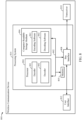
- FIG. 8 is a block diagram illustrating an example of a hardware implementation for a wireless communication device 800 employing a processing system 814.
- a processing system 814 that includes one or more processors 804.
- the wireless communication device 800 may be a user equipment (UE), a base station, or any other suitable apparatus or means for wireless communication.
- processors 804 include microprocessors, microcontrollers, digital signal processors (DSPs), field programmable gate arrays (FPGAs), programmable logic devices (PLDs), state machines, gated logic, discrete hardware circuits, and other suitable hardware configured to perform the various functionality described throughout this disclosure. That is, the processor 804, as utilized in a wireless communication device 800, may be used to implement any one or more of the processes described below and illustrated in FIGs. 9-12 .
- the processing system 814 may be implemented with a bus architecture, represented generally by the bus 802.
- the bus 802 may include any number of interconnecting buses and bridges depending on the specific application of the processing system 814 and the overall design constraints.
- the bus 802 links together various circuits including one or more processors (represented generally by the processor 804), a memory 805, and computer-readable media (represented generally by the computer-readable medium 806).
- the bus 802 may also link various other circuits such as timing sources, peripherals, voltage regulators, and power management circuits, which are well known in the art, and therefore, will not be described any further.
- a bus interface 808 provides an interface between the bus 802 and a transceiver 810.
- the transceiver 810 provides a means for communicating with various other apparatus over a transmission medium.
- a user interface 812 e.g., keypad, display, speaker, microphone, joystick
- the processor 804 may include an encoder 841, which may in some examples operate in coordination with encoding software 861 stored in the computer-readable storage medium 806. Further, the processor 804 may include a decoder 842, which may in some examples operate in coordination with decoding software 862 stored in the computer-readable medium 806.
- the processor 804 is responsible for managing the bus 802 and general processing, including the execution of software stored on the computer-readable medium 806.
- the software when executed by the processor 804, causes the processing system 814 to perform the various functions described below for any particular apparatus.
- the computer-readable medium 806 may also be used for storing data that is manipulated by the processor 804 when executing software.
- One or more processors 804 in the processing system may execute software.
- Software shall be construed broadly to mean instructions, instruction sets, code, code segments, program code, programs, subprograms, software modules, applications, software applications, software packages, routines, subroutines, objects, executables, threads of execution, procedures, functions, etc., whether referred to as software, firmware, middleware, microcode, hardware description language, or otherwise.
- the software may reside on a computer-readable medium 806.
- the computer-readable medium 806 may be a non-transitory computer-readable medium.
- a non-transitory computer-readable medium includes, by way of example, a magnetic storage device (e.g., hard disk, floppy disk, magnetic strip), an optical disk (e.g., a compact disc (CD) or a digital versatile disc (DVD)), a smart card, a flash memory device (e.g., a card, a stick, or a key drive), a random access memory (RAM), a read only memory (ROM), a programmable ROM (PROM), an erasable PROM (EPROM), an electrically erasable PROM (EEPROM), a register, a removable disk, and any other suitable medium for storing software and/or instructions that may be accessed and read by a computer.
- a magnetic storage device e.g., hard disk, floppy disk, magnetic strip
- an optical disk e.g., a compact disc (CD) or a digital versatile disc (DVD)
- a smart card e.g., a flash memory device (e.g.
- the computer-readable medium may also include, by way of example, a carrier wave, a transmission line, and any other suitable medium for transmitting software and/or instructions that may be accessed and read by a computer.
- the computer-readable medium 806 may reside in the processing system 814, external to the processing system 814, or distributed across multiple entities including the processing system 814.
- the computer-readable medium 806 may be embodied in a computer program product.
- a computer program product may include a computer-readable medium in packaging materials.
- Polar codes are the first codes with an explicit construction to provably achieve the channel capacity for symmetric binary-input discrete memoryless channels.
- the capacity may be achieved with a simple successive cancellation (SC) decoder.
- SC successive cancellation
- Polar codes and LDPC codes are two competitive candidates for 5G channel coding.
- Polar codes are block codes.
- the generate matrices of Polar codes may be submatrices of Hadamard matrices. Generally, each row of the generate matrices corresponds to a bit-channel.
- the rows of the Hadamard matrices corresponding to the good channels are selected for information bits.
- the bad channels are used for frozen bits with fixed value of zeros.
- density evolution or Gaussian approximation is generally used to determine the bit-error probability of each channel. For example, if N information bits are desired, the best N channels (with low error probability) are selected for information bits while the remaining channels are designated as frozen bits.
- bit-error probabilities of all the channels are sorted to determine the best and worst channels, and a position of each bit channel is identified by a corresponding sorting index.
- sorting indices of the bit channels are generally needed in order to construct polar codes.
- the requirement of sorting the channel quality for Polar codes is generally different from Turbo codes.
- Turbo codes it is easy to get the code word as long as the code structure is defined.
- Polar codes to support different block sizes with different rates, different position sets for information bits are required indicating different possibilities for positions of the information bits.
- the position sets for information bits may be different even for the same block size with different rates.
- the memory required to store the vectors may be, for example, 100 times more assuming only 100 variable block sizes are used for each rate.
- the memory required to store the vectors e.g., sorting indices
- the position of information bits is generally very large.
- Certain aspects of the present disclosure discuss techniques for constructing polar codes including generating vectors or sorting indices indicating position sets of information bits for the construction dynamically (e.g., "on the fly"), instead of storing pre-defined vectors in memory, thus saving memory and leading to a more efficient construction of polar codes for both traffic and control channels.
- a scheme of density evolution or Gaussian approximation may be used to determine channel quality (e.g., bit error probability for each bit channel).
- Density evolution has been known to be used for construction of polar codes, and is generally known to those skilled in the art, and therefore the details thereof are not described herein. It has also been known in the art to use a lower complexity version of density evolution utilizing Gaussian approximation (GA) of densities, for the construction of polar codes. Gaussian approximation is also known to those skilled in the art. Because of lower complexity, GA is widely used. Let's assume an all-zero code word with BPSK modulation is transmitted over Additive While Gaussian Channel (AWGN) channel. The mean and the variance of the receive Loglikelihood ratio (LLR) may be 2 ⁇ 2 and 4 ⁇ 2 , respectively.
- LLR Loglikelihood ratio
- input may be given by,
- Output of the GA scheme may be the sorting index of e 0 , i or the vector for the indication of the positions for information bits and frozen bits.
- the output may be determined based on the noise variance and coded block size N.
- the vector of good channel positions (or sorting indices) may be generated on the fly as long as the noise variance and coded block size are known.
- the function and anti-function of ⁇ (x) may be implemented by a look-up table for simplification.
- the algorithm shown above may be modified to support variable blocks sizes by considering puncture patterns.
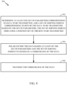
- FIG. 9 illustrates example operations 900 performed by a transmitter (e.g., UE, eNB or any other network node or element thereof) for efficient construction of polar codes, in accordance with certain aspects of the present disclosure.
- Operations 900 begin, at 902, by determining at least one set of parameters corresponding to data to be transmitted and a set of indices (e.g., sorting indices) corresponding to bits of the data to be transmitted based on the set of parameters, the set of sorting indices indicating a position set of the bits to be transmitted.
- the transmitter polar encodes the data based at least on the set of parameters and the set of sorting indices to generate a coded block of the data.
- the transmitter transmits the coded block of the data.
- the set of parameters includes information block size K, coded block size N or construction SNR of 1 ⁇ 2 , or a combination thereof.
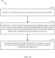
- FIG. 10 illustrates example operations 1000 performed by a receiver (e.g., UE, eNB or any other network node or element thereof) for efficient construction of polar codes, in accordance with certain aspects of the present disclosure.
- Operations 1000 begin, at 1002, by receiving a coded block of data generated by polar encoding.
- the receiver determines at least one set of parameters corresponding to the data and a set of sorting indices corresponding to bits of the data, based on the set of parameters, the set of sorting indices indicating a position set of the bits of the data.
- the receiver decodes the received coded block of data based at least on the set of parameters and the set of sorting indices to obtain decoded data.
- the position set for information bits of data is necessary for construction of Polar codes. To obtain good performance, a large memory is needed to store the binary vectors which represent the position set.
- GA algorithm is widely used to generate sorting index of the channel quality or the corresponding vector.
- the sorting index is determined based on parameters including the information block size K, the coded block size N and the construction SNR of 1 ⁇ 2 , it is easy for both the transmitter and receiver to generate the sorting indices on the fly as long as the three factors are known to them.
- a device may determine the information block size K and the coded block size N from control information known to the device.
- the construction SNR ⁇ may be obtained from a predefined look-up, each pair of (N, K) in the look-up table corresponding to a particular value of the construction SNR ⁇ .
- aspects of the present disclosure propose generating the sorting indices of the channel quality or the vectors on the fly in both transmitter and receiver.
- the coded block size N i of code blocks1106 may be determined, for example, based on the amount of resources allocated for transmission of the data. In an aspect, overhead such as reference signals is removed when the actual resource size is calculated. In an aspect, the coded block size N i may vary based on the allocated resource. For example, in LTE, different PRBs may have different amount of REs allocated for reference signals (RSs). These REs allocated for the RSs are generally removed from consideration before determining the actual resource size for calculating the coded block size. Different PRBs may have different amounts of REs allocated for RSs and thus may result in different coded block sizes.
- RSs reference signals
- noise variance 1108 (e.g., construction SNR ⁇ i ) is obtained based on the code block size N i and the information block size K i , for example from a predefined look-up table.
- each pair of (N i , K i ) is mapped to a specific value for each construction SNR ⁇ i 1108.
- a value of the construction SNR ⁇ i is looked up from the look-up table, the value of the construction SNR ⁇ i in the look-up table corresponding to a combination of a value of the code block size N i and a value of the information block size K i .
- the same predefined look-up table for mapping (N i , K i ) into ⁇ i is applied for both transmitter and receiver.
- the position set of the information bits obtained at the transmitter is substantially identical to that obtained at the receiver.
- the received signal may be decoded correctly block by block at the receiver, for example, based on the parameter set (N i , K i , ⁇ i ) and the sorting indices determined at the receiver.
- each pair of (N i , K i ) corresponds to a specific value of construction SNR ⁇ i .
- the values of the construction SNR ⁇ i are optimized based on N i and K i predefined in the table.
- a puncture pattern 1210 is determined. After the puncture pattern 1210 has been determined, the sorting index 1212 of the channel quality is obtained by the GA algorithm using parameters of (N i , K i , ⁇ i ). In this way, the position set of the information bits is determined by the sorting indices 1212.
- the coded block 1214 is obtained by Polar encoding and puncturing according to the puncture pattern.
Landscapes
- Engineering & Computer Science (AREA)
- Physics & Mathematics (AREA)
- Computer Networks & Wireless Communication (AREA)
- Signal Processing (AREA)
- Theoretical Computer Science (AREA)
- Probability & Statistics with Applications (AREA)
- Quality & Reliability (AREA)
- Electromagnetism (AREA)
- Mobile Radio Communication Systems (AREA)
- Error Detection And Correction (AREA)
- Transmission Systems Not Characterized By The Medium Used For Transmission (AREA)
- Compression, Expansion, Code Conversion, And Decoders (AREA)
- Adornments (AREA)
Applications Claiming Priority (3)
| Application Number | Priority Date | Filing Date | Title |
|---|---|---|---|
| PCT/CN2016/091592 WO2018018370A1 (en) | 2016-07-25 | 2016-07-25 | Methods and apparatus for constructing polar codes |
| PCT/CN2017/089977 WO2018019067A1 (en) | 2016-07-25 | 2017-06-26 | Methods and apparatus for constructing polar codes |
| EP17833370.4A EP3488543A4 (de) | 2016-07-25 | 2017-06-26 | Verfahren und vorrichtung zur konstruktion von polarcodes |
Related Parent Applications (1)
| Application Number | Title | Priority Date | Filing Date |
|---|---|---|---|
| EP17833370.4A Division EP3488543A4 (de) | 2016-07-25 | 2017-06-26 | Verfahren und vorrichtung zur konstruktion von polarcodes |
Publications (2)
| Publication Number | Publication Date |
|---|---|
| EP4398489A2 true EP4398489A2 (de) | 2024-07-10 |
| EP4398489A3 EP4398489A3 (de) | 2024-09-11 |
Family
ID=61015623
Family Applications (3)
| Application Number | Title | Priority Date | Filing Date |
|---|---|---|---|
| EP16909951.2A Withdrawn EP3488530A1 (de) | 2016-07-25 | 2016-07-25 | Verfahren und vorrichtung zur konstruktion von polarcodes |
| EP17833370.4A Ceased EP3488543A4 (de) | 2016-07-25 | 2017-06-26 | Verfahren und vorrichtung zur konstruktion von polarcodes |
| EP24178153.3A Pending EP4398489A3 (de) | 2016-07-25 | 2017-06-26 | Verfahren und vorrichtung zur konstruktion von polaren codes |
Family Applications Before (2)
| Application Number | Title | Priority Date | Filing Date |
|---|---|---|---|
| EP16909951.2A Withdrawn EP3488530A1 (de) | 2016-07-25 | 2016-07-25 | Verfahren und vorrichtung zur konstruktion von polarcodes |
| EP17833370.4A Ceased EP3488543A4 (de) | 2016-07-25 | 2017-06-26 | Verfahren und vorrichtung zur konstruktion von polarcodes |
Country Status (4)
| Country | Link |
|---|---|
| US (4) | US11128316B2 (de) |
| EP (3) | EP3488530A1 (de) |
| CN (2) | CN109478897B (de) |
| WO (2) | WO2018018370A1 (de) |
Families Citing this family (11)
| Publication number | Priority date | Publication date | Assignee | Title |
|---|---|---|---|---|
| EP3488530A1 (de) | 2016-07-25 | 2019-05-29 | Qualcomm Incorporated | Verfahren und vorrichtung zur konstruktion von polarcodes |
| CN107800510B (zh) * | 2016-09-05 | 2020-11-17 | 华为技术有限公司 | 极化Polar码编码的方法及装置 |
| US10176761B2 (en) * | 2017-02-23 | 2019-01-08 | Synaptics Incorporated | Compressed data transmission in panel display system |
| CN108809486B (zh) * | 2017-05-03 | 2020-09-04 | 华为技术有限公司 | Polar码编译码方法及装置 |
| CN109286404B (zh) | 2017-07-21 | 2021-02-09 | 华为技术有限公司 | 一种Polar码编码方法及装置 |
| CN110113282B (zh) * | 2019-04-19 | 2021-07-20 | 苏州大学 | 基于极化码辅助的概率类papr抑制的方法 |
| CN111010255B (zh) * | 2019-11-22 | 2022-03-01 | 苏州大学 | 基于极化码编码im/dd传输方法及系统 |
| KR102706925B1 (ko) | 2019-12-24 | 2024-09-13 | 삼성전자주식회사 | 통신 시스템에서 극부호의 복호화 장치 및 방법 |
| CN115412198B (zh) * | 2021-05-27 | 2025-01-14 | 中国移动通信有限公司研究院 | Bipcm的映射关系生成方法、信息位集合确定方法及设备 |
| CN120937277A (zh) * | 2023-03-23 | 2025-11-11 | 华为技术有限公司 | 用于极化编码中比特值放置的方法、系统和装置 |
| CN120017209A (zh) * | 2023-11-15 | 2025-05-16 | 华为技术有限公司 | 一种用于通信的方法、装置、系统、存储介质和程序产品 |
Family Cites Families (41)
| Publication number | Priority date | Publication date | Assignee | Title |
|---|---|---|---|---|
| US20020194571A1 (en) * | 2001-06-13 | 2002-12-19 | Michael Parr | System and method of coding cyclic redundancy check bits to enhance frequency reuse in a communications network |
| US7459127B2 (en) * | 2002-02-26 | 2008-12-02 | Siemens Healthcare Diagnostics Inc. | Method and apparatus for precise transfer and manipulation of fluids by centrifugal and/or capillary forces |
| US7702986B2 (en) * | 2002-11-18 | 2010-04-20 | Qualcomm Incorporated | Rate-compatible LDPC codes |
| US8325826B2 (en) | 2005-03-09 | 2012-12-04 | Qualcomm Incorporated | Methods and apparatus for transmitting signals facilitating antenna control |
| KR101298745B1 (ko) * | 2005-11-07 | 2013-08-21 | 에이전시 포 사이언스, 테크놀로지 앤드 리서치 | 데이터를 복호화 및 부호화하는 방법 및 장치 |
| US7934146B2 (en) * | 2006-10-18 | 2011-04-26 | Nokia Corporation | Method, apparatus and computer program product providing for data block encoding and decoding |
| CN102122966B (zh) * | 2011-04-15 | 2012-11-14 | 北京邮电大学 | 基于信道极化的交错结构重复码的编码器及其编译码方法 |
| CN102164025B (zh) | 2011-04-15 | 2013-06-05 | 北京邮电大学 | 基于重复编码和信道极化的编码器及其编译码方法 |
| US9176927B2 (en) * | 2011-11-08 | 2015-11-03 | The Royal Institution For The Advancement Of Learning/Mcgill University | Methods and systems for decoding polar codes |
| CN103368583B (zh) * | 2012-04-11 | 2016-08-17 | 华为技术有限公司 | 极性码的译码方法和译码装置 |
| US8347186B1 (en) * | 2012-04-19 | 2013-01-01 | Polaran Yazilim Bilisim Danismanlik Ithalat Ihracat Sanayi Ticaret Limited Sirketi | Method and system for error correction in transmitting data using low complexity systematic encoder |
| US9503126B2 (en) * | 2012-07-11 | 2016-11-22 | The Regents Of The University Of California | ECC polar coding and list decoding methods and codecs |
| US9642138B2 (en) * | 2012-07-16 | 2017-05-02 | Qualcomm Incorporated | Systems and methods for frequency interleaving for whitespace transmission |
| CN103684477B (zh) * | 2012-09-24 | 2017-02-01 | 华为技术有限公司 | 混合极性码的生成方法和生成装置 |
| CN103780329B (zh) * | 2012-10-17 | 2018-05-04 | 华为技术有限公司 | 一种编译码的方法、装置及系统 |
| CN107659384A (zh) | 2012-11-16 | 2018-02-02 | 华为技术有限公司 | 数据处理的方法和装置 |
| KR101951663B1 (ko) * | 2012-12-14 | 2019-02-25 | 삼성전자주식회사 | Crc 부호와 극 부호에 의한 부호화 방법 및 장치 |
| US9083387B2 (en) * | 2012-12-18 | 2015-07-14 | Samsung Electronics Co., Ltd. | Communication system with compound coding mechanism and method of operation thereof |
| CN103023618B (zh) * | 2013-01-11 | 2015-04-22 | 北京邮电大学 | 一种任意码长的极化编码方法 |
| US9362956B2 (en) * | 2013-01-23 | 2016-06-07 | Samsung Electronics Co., Ltd. | Method and system for encoding and decoding data using concatenated polar codes |
| KR101710025B1 (ko) * | 2013-01-24 | 2017-02-24 | 캘리포니아 인스티튜트 오브 테크놀로지 | 재기록 불능 메모리에서의 결합 재기록 및 에러 정정 |
| CN104079370B (zh) | 2013-03-27 | 2018-05-04 | 华为技术有限公司 | 信道编译码方法及装置 |
| CN103281166B (zh) * | 2013-05-15 | 2016-05-25 | 北京邮电大学 | 一种基于极化码的混合自动重传请求传输方法 |
| CN105009541B (zh) * | 2013-07-18 | 2018-06-05 | 华为技术有限公司 | 一种低码率的编码方法和设备 |
| USRE48563E1 (en) | 2013-08-20 | 2021-05-18 | Lg Electronics Inc. | Method for transmitting data by using polar coding in wireless access system |
| US10135460B2 (en) * | 2013-10-01 | 2018-11-20 | Texas Instruments Incorporated | Apparatus and method for multilevel coding (MLC) with binary alphabet polar codes |
| BR112016008554B1 (pt) * | 2013-10-18 | 2022-08-16 | Qualcomm Incorporated | Método e aparelho para configuração de csi para mimo 3-d e memória legível por computador |
| WO2015058416A1 (zh) * | 2013-10-26 | 2015-04-30 | 华为技术有限公司 | 一种极性码的译码方法及装置 |
| CA2935256A1 (en) * | 2014-02-21 | 2015-08-27 | Huawei Technologies Co., Ltd. | Rate matching method and apparatus for polar code |
| US9317365B2 (en) * | 2014-03-06 | 2016-04-19 | Seagate Technology Llc | Soft decoding of polar codes |
| KR102128471B1 (ko) * | 2014-03-11 | 2020-06-30 | 삼성전자주식회사 | 폴라 부호의 리스트 복호 방법 및 이를 적용한 메모리 시스템 |
| CN103916220B (zh) * | 2014-04-15 | 2017-04-05 | 电子科技大学 | 一种基于极化码的网络编码协作通信方法 |
| EP3142257B1 (de) * | 2014-05-30 | 2020-08-26 | Huawei Technologies Co., Ltd. | Verfahren und vorrichtung zur erstellung eines punktierten polarcodes |
| US9602235B2 (en) * | 2014-06-27 | 2017-03-21 | Texas Instruments Incorporated | Code block segmentation and configuration for concatenated turbo and RS coding |
| US10193578B2 (en) * | 2014-07-10 | 2019-01-29 | The Royal Institution For The Advancement Of Learning / Mcgill University | Flexible polar encoders and decoders |
| CN104202276B (zh) * | 2014-07-16 | 2018-06-01 | 中兴通讯股份有限公司 | 信道信息的量化反馈、数据的预编码方法及装置 |
| AU2014415500B2 (en) * | 2014-12-22 | 2019-01-17 | Guangdong Oppo Mobile Telecommunications Corp., Ltd. | Polar code encoding method and encoding apparatus |
| KR20160080847A (ko) * | 2014-12-29 | 2016-07-08 | 한국전자통신연구원 | 다중 사용자 동시 전송을 위한 다중 편파 전송 시스템 및 방법 |
| CN105227189B (zh) * | 2015-09-24 | 2019-01-01 | 电子科技大学 | 分段crc辅助的极化码编译码方法 |
| US10312947B2 (en) * | 2016-01-21 | 2019-06-04 | Huawei Technologies Co., Ltd. | Concatenated and sliding-window polar coding |
| EP3488530A1 (de) | 2016-07-25 | 2019-05-29 | Qualcomm Incorporated | Verfahren und vorrichtung zur konstruktion von polarcodes |
-
2016
- 2016-07-25 EP EP16909951.2A patent/EP3488530A1/de not_active Withdrawn
- 2016-07-25 CN CN201680087902.0A patent/CN109478897B/zh active Active
- 2016-07-25 WO PCT/CN2016/091592 patent/WO2018018370A1/en not_active Ceased
-
2017
- 2017-06-26 EP EP17833370.4A patent/EP3488543A4/de not_active Ceased
- 2017-06-26 EP EP24178153.3A patent/EP4398489A3/de active Pending
- 2017-06-26 US US16/320,038 patent/US11128316B2/en active Active
- 2017-06-26 WO PCT/CN2017/089977 patent/WO2018019067A1/en not_active Ceased
- 2017-06-26 CN CN201780045680.0A patent/CN109478954B/zh active Active
-
2021
- 2021-07-29 US US17/443,992 patent/US11791843B2/en active Active
-
2023
- 2023-09-06 US US18/461,809 patent/US12283973B2/en active Active
-
2025
- 2025-04-21 US US19/184,665 patent/US20250253868A1/en active Pending
Also Published As
| Publication number | Publication date |
|---|---|
| US20250253868A1 (en) | 2025-08-07 |
| WO2018018370A1 (en) | 2018-02-01 |
| US20230412195A1 (en) | 2023-12-21 |
| US11128316B2 (en) | 2021-09-21 |
| US11791843B2 (en) | 2023-10-17 |
| CN109478897A (zh) | 2019-03-15 |
| US20230318626A9 (en) | 2023-10-05 |
| CN109478954B (zh) | 2022-02-15 |
| US20190268022A1 (en) | 2019-08-29 |
| EP3488543A4 (de) | 2020-03-11 |
| CN109478897B (zh) | 2023-05-12 |
| US20210359706A1 (en) | 2021-11-18 |
| EP4398489A3 (de) | 2024-09-11 |
| EP3488543A1 (de) | 2019-05-29 |
| CN109478954A (zh) | 2019-03-15 |
| US12283973B2 (en) | 2025-04-22 |
| WO2018019067A1 (en) | 2018-02-01 |
| EP3488530A1 (de) | 2019-05-29 |
Similar Documents
| Publication | Publication Date | Title |
|---|---|---|
| US12283973B2 (en) | Methods and apparatus for constructing polar codes | |
| US12010661B2 (en) | Long-term evolution compatible very narrow band design | |
| KR101590459B1 (ko) | 물리적 다운링크 공유 채널 간섭 제거에 대한 하이브리드 접근 방식 | |
| KR102746630B1 (ko) | 함께 코딩하는 것에 의한 동일한 집합 레벨의 다운링크 제어 정보의 멀티플렉싱 | |
| EP3739987B1 (de) | Techniken zur verwaltung eines ressourcenpools in drahtlosen kommunikationen | |
| US10256855B2 (en) | Interference management information signaling | |
| CN107210841B (zh) | 用于处理超低延时(ull)lte中的信道状态信息(csi)的技术 | |
| US20170163397A1 (en) | Adaptive control channel design for balancing data payload size and decoding time | |
| JP2014530540A (ja) | Lteにおける狭帯域幅動作 | |
| CN108604972A (zh) | 用于上行链路(ul)窄带物联网(nb-iot)的导频设计 | |
| KR20180037958A (ko) | 유연 이중화를 위한 기술들 | |
| US9750048B2 (en) | Feedback signal management for low latency wireless communications | |
| US8903341B2 (en) | Successive interference cancellation (SIC) ordering algorithms for improved multiple-input multiple-output (MIMO) performance | |
| US9094164B2 (en) | Methods and apparatus to improve channel estimation in communication systems | |
| CN109891770B (zh) | 波束成形系统中的共用控制的传输 | |
| CN119276421A (zh) | 极化码的信道知悉式构造 |
Legal Events
| Date | Code | Title | Description |
|---|---|---|---|
| PUAI | Public reference made under article 153(3) epc to a published international application that has entered the european phase |
Free format text: ORIGINAL CODE: 0009012 |
|
| STAA | Information on the status of an ep patent application or granted ep patent |
Free format text: STATUS: REQUEST FOR EXAMINATION WAS MADE |
|
| 17P | Request for examination filed |
Effective date: 20240527 |
|
| AC | Divisional application: reference to earlier application |
Ref document number: 3488543 Country of ref document: EP Kind code of ref document: P |
|
| AK | Designated contracting states |
Kind code of ref document: A2 Designated state(s): AL AT BE BG CH CY CZ DE DK EE ES FI FR GB GR HR HU IE IS IT LI LT LU LV MC MK MT NL NO PL PT RO RS SE SI SK SM TR |
|
| REG | Reference to a national code |
Ref country code: DE Ref legal event code: R079 Free format text: PREVIOUS MAIN CLASS: H03M0013350000 Ipc: H03M0013130000 |
|
| PUAL | Search report despatched |
Free format text: ORIGINAL CODE: 0009013 |
|
| AK | Designated contracting states |
Kind code of ref document: A3 Designated state(s): AL AT BE BG CH CY CZ DE DK EE ES FI FR GB GR HR HU IE IS IT LI LT LU LV MC MK MT NL NO PL PT RO RS SE SI SK SM TR |
|
| RIC1 | Information provided on ipc code assigned before grant |
Ipc: H03M 13/35 20060101ALI20240802BHEP Ipc: H04L 1/00 20060101ALI20240802BHEP Ipc: H03M 13/13 20060101AFI20240802BHEP |