EP4398393A2 - Battery pack and vehicle including battery pack - Google Patents
Battery pack and vehicle including battery pack Download PDFInfo
- Publication number
- EP4398393A2 EP4398393A2 EP24175094.2A EP24175094A EP4398393A2 EP 4398393 A2 EP4398393 A2 EP 4398393A2 EP 24175094 A EP24175094 A EP 24175094A EP 4398393 A2 EP4398393 A2 EP 4398393A2
- Authority
- EP
- European Patent Office
- Prior art keywords
- battery pack
- air
- battery
- plate
- cooling
- Prior art date
- Legal status (The legal status is an assumption and is not a legal conclusion. Google has not performed a legal analysis and makes no representation as to the accuracy of the status listed.)
- Pending
Links
Images




Classifications
-
- H—ELECTRICITY
- H01—ELECTRIC ELEMENTS
- H01M—PROCESSES OR MEANS, e.g. BATTERIES, FOR THE DIRECT CONVERSION OF CHEMICAL ENERGY INTO ELECTRICAL ENERGY
- H01M50/00—Constructional details or processes of manufacture of the non-active parts of electrochemical cells other than fuel cells, e.g. hybrid cells
- H01M50/20—Mountings; Secondary casings or frames; Racks, modules or packs; Suspension devices; Shock absorbers; Transport or carrying devices; Holders
-
- H—ELECTRICITY
- H01—ELECTRIC ELEMENTS
- H01M—PROCESSES OR MEANS, e.g. BATTERIES, FOR THE DIRECT CONVERSION OF CHEMICAL ENERGY INTO ELECTRICAL ENERGY
- H01M10/00—Secondary cells; Manufacture thereof
- H01M10/60—Heating or cooling; Temperature control
- H01M10/61—Types of temperature control
- H01M10/613—Cooling or keeping cold
-
- H—ELECTRICITY
- H01—ELECTRIC ELEMENTS
- H01M—PROCESSES OR MEANS, e.g. BATTERIES, FOR THE DIRECT CONVERSION OF CHEMICAL ENERGY INTO ELECTRICAL ENERGY
- H01M10/00—Secondary cells; Manufacture thereof
- H01M10/60—Heating or cooling; Temperature control
- H01M10/62—Heating or cooling; Temperature control specially adapted for specific applications
- H01M10/625—Vehicles
-
- H—ELECTRICITY
- H01—ELECTRIC ELEMENTS
- H01M—PROCESSES OR MEANS, e.g. BATTERIES, FOR THE DIRECT CONVERSION OF CHEMICAL ENERGY INTO ELECTRICAL ENERGY
- H01M10/00—Secondary cells; Manufacture thereof
- H01M10/60—Heating or cooling; Temperature control
- H01M10/64—Heating or cooling; Temperature control characterised by the shape of the cells
- H01M10/647—Prismatic or flat cells, e.g. pouch cells
-
- H—ELECTRICITY
- H01—ELECTRIC ELEMENTS
- H01M—PROCESSES OR MEANS, e.g. BATTERIES, FOR THE DIRECT CONVERSION OF CHEMICAL ENERGY INTO ELECTRICAL ENERGY
- H01M10/00—Secondary cells; Manufacture thereof
- H01M10/60—Heating or cooling; Temperature control
- H01M10/65—Means for temperature control structurally associated with the cells
- H01M10/655—Solid structures for heat exchange or heat conduction
-
- H—ELECTRICITY
- H01—ELECTRIC ELEMENTS
- H01M—PROCESSES OR MEANS, e.g. BATTERIES, FOR THE DIRECT CONVERSION OF CHEMICAL ENERGY INTO ELECTRICAL ENERGY
- H01M10/00—Secondary cells; Manufacture thereof
- H01M10/60—Heating or cooling; Temperature control
- H01M10/65—Means for temperature control structurally associated with the cells
- H01M10/655—Solid structures for heat exchange or heat conduction
- H01M10/6551—Surfaces specially adapted for heat dissipation or radiation, e.g. fins or coatings
-
- H—ELECTRICITY
- H01—ELECTRIC ELEMENTS
- H01M—PROCESSES OR MEANS, e.g. BATTERIES, FOR THE DIRECT CONVERSION OF CHEMICAL ENERGY INTO ELECTRICAL ENERGY
- H01M10/00—Secondary cells; Manufacture thereof
- H01M10/60—Heating or cooling; Temperature control
- H01M10/65—Means for temperature control structurally associated with the cells
- H01M10/655—Solid structures for heat exchange or heat conduction
- H01M10/6554—Rods or plates
-
- H—ELECTRICITY
- H01—ELECTRIC ELEMENTS
- H01M—PROCESSES OR MEANS, e.g. BATTERIES, FOR THE DIRECT CONVERSION OF CHEMICAL ENERGY INTO ELECTRICAL ENERGY
- H01M10/00—Secondary cells; Manufacture thereof
- H01M10/60—Heating or cooling; Temperature control
- H01M10/65—Means for temperature control structurally associated with the cells
- H01M10/655—Solid structures for heat exchange or heat conduction
- H01M10/6556—Solid parts with flow channel passages or pipes for heat exchange
-
- H—ELECTRICITY
- H01—ELECTRIC ELEMENTS
- H01M—PROCESSES OR MEANS, e.g. BATTERIES, FOR THE DIRECT CONVERSION OF CHEMICAL ENERGY INTO ELECTRICAL ENERGY
- H01M10/00—Secondary cells; Manufacture thereof
- H01M10/60—Heating or cooling; Temperature control
- H01M10/65—Means for temperature control structurally associated with the cells
- H01M10/656—Means for temperature control structurally associated with the cells characterised by the type of heat-exchange fluid
- H01M10/6567—Liquids
- H01M10/6568—Liquids characterised by flow circuits, e.g. loops, located externally to the cells or cell casings
-
- H—ELECTRICITY
- H01—ELECTRIC ELEMENTS
- H01M—PROCESSES OR MEANS, e.g. BATTERIES, FOR THE DIRECT CONVERSION OF CHEMICAL ENERGY INTO ELECTRICAL ENERGY
- H01M50/00—Constructional details or processes of manufacture of the non-active parts of electrochemical cells other than fuel cells, e.g. hybrid cells
- H01M50/20—Mountings; Secondary casings or frames; Racks, modules or packs; Suspension devices; Shock absorbers; Transport or carrying devices; Holders
- H01M50/204—Racks, modules or packs for multiple batteries or multiple cells
- H01M50/207—Racks, modules or packs for multiple batteries or multiple cells characterised by their shape
- H01M50/209—Racks, modules or packs for multiple batteries or multiple cells characterised by their shape adapted for prismatic or rectangular cells
-
- H—ELECTRICITY
- H01—ELECTRIC ELEMENTS
- H01M—PROCESSES OR MEANS, e.g. BATTERIES, FOR THE DIRECT CONVERSION OF CHEMICAL ENERGY INTO ELECTRICAL ENERGY
- H01M50/00—Constructional details or processes of manufacture of the non-active parts of electrochemical cells other than fuel cells, e.g. hybrid cells
- H01M50/20—Mountings; Secondary casings or frames; Racks, modules or packs; Suspension devices; Shock absorbers; Transport or carrying devices; Holders
- H01M50/204—Racks, modules or packs for multiple batteries or multiple cells
- H01M50/207—Racks, modules or packs for multiple batteries or multiple cells characterised by their shape
- H01M50/211—Racks, modules or packs for multiple batteries or multiple cells characterised by their shape adapted for pouch cells
-
- H—ELECTRICITY
- H01—ELECTRIC ELEMENTS
- H01M—PROCESSES OR MEANS, e.g. BATTERIES, FOR THE DIRECT CONVERSION OF CHEMICAL ENERGY INTO ELECTRICAL ENERGY
- H01M50/00—Constructional details or processes of manufacture of the non-active parts of electrochemical cells other than fuel cells, e.g. hybrid cells
- H01M50/20—Mountings; Secondary casings or frames; Racks, modules or packs; Suspension devices; Shock absorbers; Transport or carrying devices; Holders
- H01M50/218—Mountings; Secondary casings or frames; Racks, modules or packs; Suspension devices; Shock absorbers; Transport or carrying devices; Holders characterised by the material
- H01M50/22—Mountings; Secondary casings or frames; Racks, modules or packs; Suspension devices; Shock absorbers; Transport or carrying devices; Holders characterised by the material of the casings or racks
- H01M50/227—Organic material
-
- H—ELECTRICITY
- H01—ELECTRIC ELEMENTS
- H01M—PROCESSES OR MEANS, e.g. BATTERIES, FOR THE DIRECT CONVERSION OF CHEMICAL ENERGY INTO ELECTRICAL ENERGY
- H01M50/00—Constructional details or processes of manufacture of the non-active parts of electrochemical cells other than fuel cells, e.g. hybrid cells
- H01M50/20—Mountings; Secondary casings or frames; Racks, modules or packs; Suspension devices; Shock absorbers; Transport or carrying devices; Holders
- H01M50/233—Mountings; Secondary casings or frames; Racks, modules or packs; Suspension devices; Shock absorbers; Transport or carrying devices; Holders characterised by physical properties of casings or racks, e.g. dimensions
- H01M50/242—Mountings; Secondary casings or frames; Racks, modules or packs; Suspension devices; Shock absorbers; Transport or carrying devices; Holders characterised by physical properties of casings or racks, e.g. dimensions adapted for protecting batteries against vibrations, collision impact or swelling
-
- H—ELECTRICITY
- H01—ELECTRIC ELEMENTS
- H01M—PROCESSES OR MEANS, e.g. BATTERIES, FOR THE DIRECT CONVERSION OF CHEMICAL ENERGY INTO ELECTRICAL ENERGY
- H01M50/00—Constructional details or processes of manufacture of the non-active parts of electrochemical cells other than fuel cells, e.g. hybrid cells
- H01M50/20—Mountings; Secondary casings or frames; Racks, modules or packs; Suspension devices; Shock absorbers; Transport or carrying devices; Holders
- H01M50/249—Mountings; Secondary casings or frames; Racks, modules or packs; Suspension devices; Shock absorbers; Transport or carrying devices; Holders specially adapted for aircraft or vehicles, e.g. cars or trains
-
- H—ELECTRICITY
- H01—ELECTRIC ELEMENTS
- H01M—PROCESSES OR MEANS, e.g. BATTERIES, FOR THE DIRECT CONVERSION OF CHEMICAL ENERGY INTO ELECTRICAL ENERGY
- H01M50/00—Constructional details or processes of manufacture of the non-active parts of electrochemical cells other than fuel cells, e.g. hybrid cells
- H01M50/20—Mountings; Secondary casings or frames; Racks, modules or packs; Suspension devices; Shock absorbers; Transport or carrying devices; Holders
- H01M50/289—Mountings; Secondary casings or frames; Racks, modules or packs; Suspension devices; Shock absorbers; Transport or carrying devices; Holders characterised by spacing elements or positioning means within frames, racks or packs
-
- H—ELECTRICITY
- H01—ELECTRIC ELEMENTS
- H01M—PROCESSES OR MEANS, e.g. BATTERIES, FOR THE DIRECT CONVERSION OF CHEMICAL ENERGY INTO ELECTRICAL ENERGY
- H01M50/00—Constructional details or processes of manufacture of the non-active parts of electrochemical cells other than fuel cells, e.g. hybrid cells
- H01M50/30—Arrangements for facilitating escape of gases
- H01M50/35—Gas exhaust passages comprising elongated, tortuous or labyrinth-shaped exhaust passages
-
- H—ELECTRICITY
- H01—ELECTRIC ELEMENTS
- H01M—PROCESSES OR MEANS, e.g. BATTERIES, FOR THE DIRECT CONVERSION OF CHEMICAL ENERGY INTO ELECTRICAL ENERGY
- H01M2220/00—Batteries for particular applications
- H01M2220/20—Batteries in motive systems, e.g. vehicle, ship, plane
-
- Y—GENERAL TAGGING OF NEW TECHNOLOGICAL DEVELOPMENTS; GENERAL TAGGING OF CROSS-SECTIONAL TECHNOLOGIES SPANNING OVER SEVERAL SECTIONS OF THE IPC; TECHNICAL SUBJECTS COVERED BY FORMER USPC CROSS-REFERENCE ART COLLECTIONS [XRACs] AND DIGESTS
- Y02—TECHNOLOGIES OR APPLICATIONS FOR MITIGATION OR ADAPTATION AGAINST CLIMATE CHANGE
- Y02E—REDUCTION OF GREENHOUSE GAS [GHG] EMISSIONS, RELATED TO ENERGY GENERATION, TRANSMISSION OR DISTRIBUTION
- Y02E60/00—Enabling technologies; Technologies with a potential or indirect contribution to GHG emissions mitigation
- Y02E60/10—Energy storage using batteries
Definitions
- the present disclosure is also directed to providing a battery pack, which may buffer an external impact or the like, and a vehicle including the battery pack.
- Various embodiments of the battery pack may present one or more of the features of the dependent claims 2 to 8, in any allowed and technically feasible combination.
- a battery pack which may improve the efficiency of the assembling process and secure a high energy density, and a vehicle including the battery pack.
- a battery pack which may improve the cooling efficiency, and a vehicle including the battery pack.
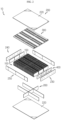
- FIG. 1 is a diagram for illustrating a battery pack according to an embodiment of the present disclosure
- FIG. 2 is an exploded perspective view showing the battery pack of FIG. 1
- FIG. 3 is a diagram for illustrating a pack case of the battery pack of FIG. 2
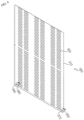
- FIG. 4 is a diagram for illustrating a cooling mat of FIG. 2
- FIGS. 5 to 7 are diagrams for illustrating main parts of the cooling mat of FIG. 4
- FIG. 8 is a diagram for illustrating an air cushion of FIG. 2 .
- the battery pack 10 includes a battery cell 100, a pack case 200 and a cooling mat 300.
- the lead passing hole 320 is formed in the mat body 310 and may allow the electrode leads 150 of the plurality of battery cells 100 to pass therethrough. To this end, the lead passing hole 320 may be provided in plural.
- FIG. 9 is a diagram for illustrating a vehicle according to an embodiment of the present disclosure.
- the battery pack 10 which may improve the efficiency of the assembling process and secure a high energy density, and the vehicle V including the battery pack 10.
- the battery pack 10 which may improve the cooling efficiency, and the vehicle V including the battery pack 10.
Landscapes
- Chemical & Material Sciences (AREA)
- Chemical Kinetics & Catalysis (AREA)
- Electrochemistry (AREA)
- General Chemical & Material Sciences (AREA)
- Engineering & Computer Science (AREA)
- Manufacturing & Machinery (AREA)
- Aviation & Aerospace Engineering (AREA)
- Secondary Cells (AREA)
- Battery Mounting, Suspending (AREA)
Abstract
Description
- The present disclosure relates to a battery pack and a vehicle including the battery pack.
- Secondary batteries which are highly applicable to various products and exhibit superior electrical properties such as high energy density, etc. are commonly used not only in portable devices but also in electric vehicles (EVs) or hybrid electric vehicles (HEVs) driven by electrical power sources. The secondary battery is drawing attentions as a new energy source for enhancing energy efficiency and environment friendliness in that the use of fossil fuels can be reduced greatly and no byproduct is generated during energy consumption.
- Secondary batteries widely used at present include lithium ion batteries, lithium polymer batteries, nickel cadmium batteries, nickel hydrogen batteries, nickel zinc batteries and the like. An operating voltage of the unit secondary battery cell, namely a unit battery cell, is about 2.5V to 4.5V. Therefore, if a higher output voltage is required, a plurality of battery cells may be connected in series to configure a battery pack. In addition, depending on the charge/discharge capacity required for the battery pack, a plurality of battery cells may be connected in parallel to configure a battery pack. Thus, the number of battery cells included in the battery pack may be variously set according to the required output voltage or the demanded charge/discharge capacity.
- Meanwhile, when a plurality of battery cells are connected in series or in parallel to configure a battery pack, it is common to configure a battery module composed of at least one battery cell first, and then configure a battery pack by using at least one battery module and adding other components.
- Examples of battery packs are given in documents
US 2014/087231 A1 ,KR 2018/0017695 A KR 2016/0024187 A KR 2013/ 008298 A - Regarding the conventional battery pack, recently, the demand of consumers for a battery pack having a high capacity and a high energy density along with a slimmer and more compact design is increasing. In order to manufacture a battery pack for realizing the high energy density, more battery cells are needed, which may make the assembling process complicated. Thus, it is also required to improve the process efficiency.
- Therefore, there is a demand for providing a battery pack capable of increasing the efficiency of the assembling process while securing a high energy density, and a vehicle including the battery pack.
- The present disclosure is directed to providing a battery pack, which may improve the efficiency of the assembling process and secure a high energy density, and a vehicle including the battery pack.
- In addition, the present disclosure is also directed to providing a battery pack, which may improve the cooling efficiency, and a vehicle including the battery pack.
- Moreover, the present disclosure is also directed to providing a battery pack, which may buffer an external impact or the like, and a vehicle including the battery pack.
- In one aspect of the present disclosure, there is provided a battery pack according to claim 1.
- Various embodiments of the battery pack may present one or more of the features of the dependent claims 2 to 8, in any allowed and technically feasible combination.
- In addition, the present disclosure provides a vehicle according to claim 9.
- According to various embodiments as above, it is possible to provide a battery pack, which may improve the efficiency of the assembling process and secure a high energy density, and a vehicle including the battery pack.
- In addition, according to various embodiments as above, it is possible to provide a battery pack, which may improve the cooling efficiency, and a vehicle including the battery pack.
- Moreover, according to various embodiments as above, it is possible to provide a battery pack, which may buffer an external impact or the like, and a vehicle including the battery pack.
- The accompanying drawings illustrate a preferred embodiment of the present disclosure and together with the foregoing disclosure, serve to provide further understanding of the technical features of the present disclosure, and thus, the present disclosure is not construed as being limited to the drawing.
-
FIG. 1 is a diagram for illustrating a battery pack according to an embodiment of the present disclosure. -
FIG. 2 is an exploded perspective view showing the battery pack ofFIG. 1 . -
FIG. 3 is a diagram for illustrating a pack case of the battery pack ofFIG. 2 . -
FIG. 4 is a diagram for illustrating a cooling mat ofFIG. 2 . -
FIGS. 5 to 7 are diagrams for illustrating main parts of the cooling mat ofFIG. 4 . -
FIG. 8 is a diagram for illustrating an air cushion ofFIG. 2 . -
FIG. 9 is a diagram for illustrating a vehicle according to an embodiment of the present disclosure. - The present disclosure will become more apparent by describing in detail the embodiments of the present disclosure with reference to the accompanying drawings. It should be understood that the embodiments disclosed herein are illustrative only for better understanding of the present disclosure, and that the present disclosure may be modified in various ways. In addition, for ease understanding of the present disclosure, the accompanying drawings are not drawn to real scale, but the dimensions of some components may be exaggerated.
-
FIG. 1 is a diagram for illustrating a battery pack according to an embodiment of the present disclosure,FIG. 2 is an exploded perspective view showing the battery pack ofFIG. 1 ,FIG. 3 is a diagram for illustrating a pack case of the battery pack ofFIG. 2 ,FIG. 4 is a diagram for illustrating a cooling mat ofFIG. 2 ,FIGS. 5 to 7 are diagrams for illustrating main parts of the cooling mat ofFIG. 4 , andFIG. 8 is a diagram for illustrating an air cushion ofFIG. 2 . - Referring to
FIGS. 1 to 8 , thebattery pack 10 includes abattery cell 100, apack case 200 and acooling mat 300. - The
battery cell 100 may be provided as a secondary battery. Thebattery cell 100 may be provided as a pouch-type secondary battery, a rectangular secondary battery or a cylindrical secondary battery. Hereinafter, in this embodiment, thebattery cell 100 will be described as a pouch-type secondary battery. - The
battery cell 100 may be provided in plural. The plurality ofbattery cells 100 may be stacked so as to be electrically connected to each other. The electrical connection may be made through the connection of electrode leads 150 of the plurality ofbattery cells 100 and a bus bar. - The
pack case 200 may accommodate the plurality ofbattery cells 100. Thepack case 200 may have accommodation spaces that may partition and accommodation the plurality ofbattery cells 100 at least partially. - The
pack case 200 may include abase plate 210, acover plate 220, afront plate 230, arear plate 240, aside plate 250 and apartition plate 260. - The
base plate 210 supports the plurality ofbattery cells 100 and may have a plate shape of a predetermined size. Thebase plate 210 may be fixedly mounted to a vehicle V (seeFIG. 9 ), explained later. - The
cover plate 220 may cover upper portions of the plurality ofbattery cells 100. A coolingwater supply tube 340, a coolingwater discharge tube 350, anair injection hole 360 and aventing hole unit 370 of thecooling mat 300, explained later, may be provided through thecover plate 220. - The
front plate 230 is mounted to a front side of thebase plate 210 and may form the front of thepack case 200. Thefront plate 230 may have a plurality ofperforation holes 235 through which anair injection hole 410 and aventing hole unit 430 of anair cushion 400, explained later, may be provided. - The
rear plate 240 is disposed opposite thefront plate 230 and may be mounted to a rear side of thebase plate 210 to form the rear of thepack case 200. - The
rear plate 240 may have a plurality ofperforation holes 245 through which theair injection hole 410 and theventing hole unit 430 of theair cushion 400, explained later, may be provided. - The
side plate 250 may be provided in a pair. The pair ofside plates 250 are mounted to thebase plate 210 to be provided between therear plate 240 and thefront plate 230 and may be disposed to be spaced apart from each other along a width direction of thebase plate 210. - The
partition plate 260 partitions an area between the pair ofside plates 250 to form the accommodation spaces and may be provided between thefront plate 230 and therear plate 240 in a front and rear direction of thebase plate 210. - By means of the
partition plate 260, the plurality ofbattery cells 100 may be partitioned and accommodated in a predetermined number. In this embodiment, since thepack case 200 includes thepartition plate 260, the plurality ofbattery cells 100 may be partitioned into a predetermined number and mounted to be directly accommodated in thepack case 200. - Accordingly, in this embodiment, since a structure such as a module case for separately packaging the predetermined number of
battery cells 100 is not required, thebattery pack 10 may have a slimmer and more compact design and secure a high energy density to give a high capacity. - Moreover, in this embodiment, since a structure such as a separate module case is eliminated, the assembling process may be simplified, thereby improving the process efficiency and lowering the manufacturing cost.
- The cooling
mat 300 is disposed in contact with upper surfaces of the plurality ofbattery cells 100 inside thepack case 200. To this end, the coolingmat 300 may be sized to entirely cover the upper surfaces of the plurality ofbattery cells 100. - The cooling
mat 300 may include amat body 310, alead passing hole 320, acooling channel 330, a coolingwater supply tube 340, a coolingwater discharge tube 350, anair injection hole 360, and aventing hole unit 370. - The
mat body 310 may be made of a rubber material with a predetermined volume. Themat body 310 is in direct contact with the upper surfaces of the plurality ofbattery cells 100 and is filled with a predetermined air therein to buffer an external impact or the like. - The
lead passing hole 320 is formed in themat body 310 and may allow the electrode leads 150 of the plurality ofbattery cells 100 to pass therethrough. To this end, thelead passing hole 320 may be provided in plural. - The cooling
channel 330 is formed in themat body 310. A cooling water for cooling the plurality ofbattery cells 100 flows in thecooling channel 330. - The cooling
channel 330 may be formed in a space between the electrode leads 150 of the plurality ofbattery cells 100 to avoid interference with the electrode leads 150 of the plurality ofbattery cells 100. - In this embodiment, the cooling
channel 330 is provided, and it is possible to significantly improve the cooling performance of the plurality ofbattery cells 100 by means of the coolingmat 300 in direct contact with the plurality ofbattery cells 100. - The cooling
water supply tube 340 may be provided in themat body 310 to communicate with the coolingchannel 330. The coolingwater supply tube 340 may protrude out of thecover plate 220 of thepack case 200 to receive the cooling water from the outside. - The cooling
water discharge tube 350 may be provided to themat body 310 to communicate with the coolingchannel 330. The coolingwater discharge tube 350 may protrude out of thecover plate 220 of thepack case 200 to discharge the cooling water to the outside. - The
air injection hole 360 is for injecting an air into themat body 310 and may be provided in themat body 310. Theair injection hole 360 may protrude out of thecover plate 220 of thepack case 200 to easily inject the air from the outside. - Through the
air injection hole 360, a manufacturer or user of thebattery pack 10 may periodically inject an air into themat body 310 to maintain the inside of thebattery pack 10 at a constant pressure. - The venting
hole unit 370 may discharge the air inside themat body 310 to the outside at a predetermined pressure or above. To this end, the ventinghole unit 370 may protrude out of thecover plate 220 of thepack case 200. - Since the
battery pack 10 discharges the air inside themat body 310 to the outside through theventing hole unit 370 when the internal pressure increases due to the inflation of the plurality ofbattery cells 100, it is possible to minimize a rapid increase of the internal pressure of thebattery pack 10. - Meanwhile, the
battery pack 10 includes anair cushion 400. - The
air cushion 400 is disposed perpendicular to thecooling mat 300 and may be mounted to inner walls of thepack case 200 along a front and rear direction. In detail, theair cushion 400 may be mounted to an inner wall of thefront plate 230 and an inner wall of therear plate 240. - The
air cushion 400 may be provided in plural, and the plurality ofair cushions 400 may be made of a rubber material, similar to thecooling mat 300, and be filled with a predetermined air therein to buffer an external impact or the like. - The
air cushion 400 may include anair injection hole 410 and aventing hole unit 430. - The
air injection hole 410 is for injecting an air into theair cushion 400 and may protrude out of thefront plate 230 and therear plate 240 of thepack case 200 to easily inject the air from the outside. - Through the
air injection hole 410, the manufacturer or user of thebattery pack 10 may periodically inject an air into theair cushion 400 to maintain the inside of thebattery pack 10 at a predetermined pressure. That is, the manufacturer or the user may maintain the internal pressure of thebattery pack 10 at a predetermined desired pressure by means of theair cushion 400 as well as the coolingmat 300. - The venting
hole unit 430 may discharge the air inside theair cushion 400 to the outside at a predetermined pressure or above. To this end, the ventinghole unit 430 may protrude out of thefront plate 230 and therear plate 240 of thepack case 200. - Through the
venting hole unit 430, thebattery pack 10 discharges the air inside theair cushion 400 as well as the coolingmat 300 when the internal pressure increases due to the inflation of the plurality ofbattery cells 100, thereby minimizing a rapid increase of the internal pressure of thebattery pack 10. -
FIG. 9 is a diagram for illustrating a vehicle according to an embodiment of the present disclosure. - Referring to
FIG. 9 , a vehicle V may include at least onebattery pack 10 according to the former embodiment. The vehicle V may be as an electric vehicle, a hybrid vehicle, and various other-type vehicles capable of using thebattery pack 10 as a fuel source. - In addition, the
battery pack 10 may be provided in other devices, instruments or facilities such as an energy storage system using a secondary battery, in addition to the vehicle V. - As described above, the vehicle V of this embodiment and devices, instruments or facilities such as the vehicle V, which have the
battery pack 10, include thebattery pack 10 as described above, and thus it is possible to implement devices, instruments, facilities or the like such as a vehicle V, which have all the advantages of thebattery pack 10 described above. - According to various embodiments as above, it is possible to provide the
battery pack 10, which may improve the efficiency of the assembling process and secure a high energy density, and the vehicle V including thebattery pack 10. - In addition, according to various embodiments as above, it is possible to provide the
battery pack 10, which may improve the cooling efficiency, and the vehicle V including thebattery pack 10. - Moreover, according to various embodiments as above, it is possible to provide the
battery pack 10, which may buffer an external impact or the like, and the vehicle V including thebattery pack 10. - While the embodiments of the present disclosure have been shown and described, it should be understood that the present disclosure is not limited to the specific embodiments described, and that various changes and modifications can be made within the scope of the present disclosure by those skilled in the art, and these modifications should not be understood individually from the technical ideas and views of the present disclosure.
Claims (9)
- A battery pack, comprising:a plurality of battery cells;a pack case configured to have accommodation spaces capable of partitioning and accommodating the plurality of battery cells at least partially;a cooling mat disposed to contact upper surfaces of the plurality of battery cells inside the pack case; andan air cushion disposed perpendicular to the cooling mat and mounted to inner walls of the pack case along a front and rear direction,wherein the air cushion has an air injection hole for filling a predetermined air therein, andwherein the air cushion has a venting hole unit for discharging the air at a predetermined pressure or above.
- The battery pack according to claim 1,
wherein the pack case includes:a base plate;a front plate mounted to a front side of the base plate;a rear plate disposed opposite to the front plate and mounted to a rear side of the base plate;a pair of side plates mounted to the base plate to be provided between the rear plate and the front plate and disposed to be spaced apart from each other by a predetermined distance along a width direction of the base plate; anda partition plate configured to partition an area between the pair of side plates to form the accommodation spaces and provided between the front plate and the rear plate in a front and rear direction of the base plate. - The battery pack according to claim 1,
wherein the cooling mat includes:a mat body configured to contact the upper surfaces of the plurality of battery cells; anda cooling channel formed in the mat body so that a cooling water for cooling the plurality of battery cells flows therein. - The battery pack according to claim 3,
wherein the mat body is made of a rubber material. - The battery pack according to claim 3,
wherein the mat body is filled with an air to buffer an external impact. - The battery pack according to claim 5,
wherein the mat body has an air injection hole formed therein to inject the air. - The battery pack according to claim 5,
wherein the mat body has a venting hole unit for discharging the air at a predetermined pressure or above. - The battery pack according to claim 1,
wherein the air cushion is made of a rubber material. - A vehicle, comprising at least one battery pack according to claim 1.
Applications Claiming Priority (3)
| Application Number | Priority Date | Filing Date | Title |
|---|---|---|---|
| KR1020180112332A KR102311087B1 (en) | 2018-09-19 | 2018-09-19 | Battery pack and vehicle comprising the battery pack |
| EP19862028.8A EP3792991B1 (en) | 2018-09-19 | 2019-08-26 | Battery pack and vehicle including battery pack |
| PCT/KR2019/010870 WO2020060054A1 (en) | 2018-09-19 | 2019-08-26 | Battery pack and vehicle including battery pack |
Related Parent Applications (1)
| Application Number | Title | Priority Date | Filing Date |
|---|---|---|---|
| EP19862028.8A Division EP3792991B1 (en) | 2018-09-19 | 2019-08-26 | Battery pack and vehicle including battery pack |
Publications (2)
| Publication Number | Publication Date |
|---|---|
| EP4398393A2 true EP4398393A2 (en) | 2024-07-10 |
| EP4398393A3 EP4398393A3 (en) | 2025-03-26 |
Family
ID=69848785
Family Applications (2)
| Application Number | Title | Priority Date | Filing Date |
|---|---|---|---|
| EP19862028.8A Active EP3792991B1 (en) | 2018-09-19 | 2019-08-26 | Battery pack and vehicle including battery pack |
| EP24175094.2A Pending EP4398393A3 (en) | 2018-09-19 | 2019-08-26 | Battery pack and vehicle including battery pack |
Family Applications Before (1)
| Application Number | Title | Priority Date | Filing Date |
|---|---|---|---|
| EP19862028.8A Active EP3792991B1 (en) | 2018-09-19 | 2019-08-26 | Battery pack and vehicle including battery pack |
Country Status (9)
| Country | Link |
|---|---|
| US (1) | US11462782B2 (en) |
| EP (2) | EP3792991B1 (en) |
| JP (1) | JP7096428B2 (en) |
| KR (1) | KR102311087B1 (en) |
| CN (2) | CN210403843U (en) |
| ES (1) | ES2984110T3 (en) |
| HU (1) | HUE067818T2 (en) |
| PL (1) | PL3792991T3 (en) |
| WO (1) | WO2020060054A1 (en) |
Families Citing this family (12)
| Publication number | Priority date | Publication date | Assignee | Title |
|---|---|---|---|---|
| KR102892920B1 (en) * | 2020-07-14 | 2025-11-28 | 주식회사 엘지에너지솔루션 | Battery pack and device including the same |
| KR20220025413A (en) * | 2020-08-24 | 2022-03-03 | 주식회사 엘지에너지솔루션 | Battery module and battery pack including the same |
| US11652255B2 (en) * | 2020-09-04 | 2023-05-16 | Beta Air, Llc | System and method for high energy density battery module |
| KR102917974B1 (en) | 2020-10-20 | 2026-01-23 | 주식회사 엘지에너지솔루션 | Battery module and battery pack including the same and vehicle including the same |
| KR102876434B1 (en) | 2020-11-05 | 2025-10-23 | 주식회사 엘지에너지솔루션 | Secondary battery module and secondary battery pack including the same and vehicle including the same |
| EP4498493A4 (en) * | 2022-04-04 | 2025-07-09 | Lg Energy Solution Ltd | BATTERY MODULE |
| US20240347832A1 (en) * | 2022-06-27 | 2024-10-17 | Lg Energy Solution, Ltd. | Battery pack |
| KR102815257B1 (en) * | 2022-06-27 | 2025-05-30 | 주식회사 엘지에너지솔루션 | Battery pack |
| CN115295946B (en) * | 2022-08-16 | 2024-07-16 | 小米汽车科技有限公司 | Battery Pack and Thermal Runaway Protection Design Method |
| KR20240136660A (en) * | 2023-03-07 | 2024-09-19 | 주식회사 엘지에너지솔루션 | Partition wall member including fire extinguishing pad and pack case having the same |
| KR102884936B1 (en) * | 2023-07-13 | 2025-11-12 | 주식회사 원익피앤이 | Mandrel assembly for secondary battery cell stack manufacturing equipment |
| KR20250028849A (en) * | 2023-08-22 | 2025-03-04 | 주식회사 엘지에너지솔루션 | Battery pack and vehicle comprising the same |
Citations (4)
| Publication number | Priority date | Publication date | Assignee | Title |
|---|---|---|---|---|
| KR20130008298A (en) | 2011-07-12 | 2013-01-22 | 삼성에스디아이 주식회사 | Battery pack assembly |
| US20140087231A1 (en) | 2011-03-11 | 2014-03-27 | Li-Tec Battery Gmbh | Energy storage apparatus |
| KR20160024187A (en) | 2014-08-25 | 2016-03-04 | 현대모비스 주식회사 | Battery cooling device for vehicles |
| KR20180017695A (en) | 2016-08-10 | 2018-02-21 | 주식회사 엘지화학 | Battery pack improved in cooling structure |
Family Cites Families (17)
| Publication number | Priority date | Publication date | Assignee | Title |
|---|---|---|---|---|
| JP2009301877A (en) | 2008-06-13 | 2009-12-24 | Toyoda Gosei Co Ltd | Battery pack device |
| JP5699536B2 (en) | 2010-10-26 | 2015-04-15 | ソニー株式会社 | Battery unit |
| KR101347985B1 (en) | 2012-09-05 | 2014-01-08 | 넥스콘 테크놀러지 주식회사 | Energy storage module |
| JP6090331B2 (en) | 2012-11-30 | 2017-03-08 | トヨタ自動車株式会社 | Temperature control structure of storage element |
| KR20150024724A (en) | 2013-08-27 | 2015-03-09 | 삼성에스디아이 주식회사 | Battery pack |
| EP3051607B1 (en) * | 2015-01-29 | 2018-01-03 | Volvo Car Corporation | Inflatable structure for battery protection |
| JP6404139B2 (en) | 2015-02-13 | 2018-10-10 | 株式会社マキタ | Battery pack |
| KR102154361B1 (en) | 2015-12-09 | 2020-09-09 | 주식회사 엘지화학 | Secondary battery module improved in end plate structure and end plate member for the same |
| KR102018301B1 (en) | 2016-09-01 | 2019-09-04 | 주식회사 엘지화학 | Battery module and method for fabricating the same |
| KR20180068379A (en) | 2016-12-13 | 2018-06-22 | 현대자동차주식회사 | Battery case of electric vehicle |
| KR102731558B1 (en) * | 2016-12-16 | 2024-11-18 | 현대자동차주식회사 | High voltage battery apparatus for vehicle |
| KR101916818B1 (en) | 2017-04-03 | 2018-11-08 | 이화여자대학교 산학협력단 | Method for manufacturing electronic device using large scale transferring method |
| CN206834294U (en) | 2017-05-25 | 2018-01-02 | 惠州中科新能源研究院 | The safe soft-package battery module of one kind radiating |
| CN107302069A (en) | 2017-07-12 | 2017-10-27 | 浙江谷神能源科技股份有限公司 | A kind of lithium battery Shatter-resistant device |
| CN207116551U (en) | 2017-08-31 | 2018-03-16 | 宁德时代新能源科技股份有限公司 | Battery modules and battery bag |
| PL3518312T3 (en) * | 2018-01-24 | 2025-05-05 | Samsung Sdi Co., Ltd. | Battery module comprising a housing with integrated bus bar |
| CN108493366A (en) | 2018-03-13 | 2018-09-04 | 淮北达驰电气科技有限公司 | Against shock lithium battery pack box body |
-
2018
- 2018-09-19 KR KR1020180112332A patent/KR102311087B1/en active Active
-
2019
- 2019-08-26 JP JP2021514273A patent/JP7096428B2/en active Active
- 2019-08-26 PL PL19862028.8T patent/PL3792991T3/en unknown
- 2019-08-26 EP EP19862028.8A patent/EP3792991B1/en active Active
- 2019-08-26 ES ES19862028T patent/ES2984110T3/en active Active
- 2019-08-26 EP EP24175094.2A patent/EP4398393A3/en active Pending
- 2019-08-26 WO PCT/KR2019/010870 patent/WO2020060054A1/en not_active Ceased
- 2019-08-26 US US17/052,369 patent/US11462782B2/en active Active
- 2019-08-26 HU HUE19862028A patent/HUE067818T2/en unknown
- 2019-09-17 CN CN201921546633.7U patent/CN210403843U/en active Active
- 2019-09-17 CN CN201910876256.1A patent/CN110931673B/en active Active
Patent Citations (4)
| Publication number | Priority date | Publication date | Assignee | Title |
|---|---|---|---|---|
| US20140087231A1 (en) | 2011-03-11 | 2014-03-27 | Li-Tec Battery Gmbh | Energy storage apparatus |
| KR20130008298A (en) | 2011-07-12 | 2013-01-22 | 삼성에스디아이 주식회사 | Battery pack assembly |
| KR20160024187A (en) | 2014-08-25 | 2016-03-04 | 현대모비스 주식회사 | Battery cooling device for vehicles |
| KR20180017695A (en) | 2016-08-10 | 2018-02-21 | 주식회사 엘지화학 | Battery pack improved in cooling structure |
Also Published As
| Publication number | Publication date |
|---|---|
| EP4398393A3 (en) | 2025-03-26 |
| EP3792991A1 (en) | 2021-03-17 |
| PL3792991T3 (en) | 2024-09-23 |
| HUE067818T2 (en) | 2024-11-28 |
| ES2984110T3 (en) | 2024-10-28 |
| KR20200032995A (en) | 2020-03-27 |
| CN210403843U (en) | 2020-04-24 |
| EP3792991A4 (en) | 2021-10-06 |
| WO2020060054A1 (en) | 2020-03-26 |
| KR102311087B1 (en) | 2021-10-07 |
| US20210242515A1 (en) | 2021-08-05 |
| CN110931673A (en) | 2020-03-27 |
| US11462782B2 (en) | 2022-10-04 |
| CN110931673B (en) | 2021-04-20 |
| EP3792991B1 (en) | 2024-06-19 |
| JP2021523550A (en) | 2021-09-02 |
| JP7096428B2 (en) | 2022-07-05 |
Similar Documents
| Publication | Publication Date | Title |
|---|---|---|
| EP3792991B1 (en) | Battery pack and vehicle including battery pack | |
| US11699819B2 (en) | Battery cell assembly, battery module including same battery cell assembly, battery pack including same battery module, and automobile including same battery pack | |
| US10446813B2 (en) | Battery module, and battery pack and vehicle including the same | |
| US10854936B2 (en) | Battery module, battery pack including battery module, and vehicle including battery pack | |
| US10497994B2 (en) | Battery pack and vehicle including such battery pack | |
| EP3664186A1 (en) | Battery module, and battery pack and vehicle comprising same | |
| EP4019179B1 (en) | Battery module, and battery pack and vehicle including battery module | |
| US11108091B2 (en) | Battery module, and battery pack and energy storage system including the same | |
| US10608221B2 (en) | Battery pack and vehicle including battery pack | |
| KR102455471B1 (en) | Battery cell, battery module comprising the battery cell, battery rack comprising the battery module and energy storage system comprising the battery rack | |
| EP3570343A1 (en) | Battery cell, battery module, battery pack comprising same and vehicle | |
| EP3522254B1 (en) | Battery module, battery pack including battery module, and vehicle including battery pack | |
| US20190229313A1 (en) | Battery module, and battery pack and energy storage system including the same | |
| KR20130046999A (en) | Battery cell and battery module using the same | |
| EP4027449A1 (en) | Battery module, and battery pack and vehicle including battery module | |
| EP4027448A1 (en) | Battery module, battery pack comprising battery module, and vehicle | |
| KR20190012978A (en) | Battery pack and vehicle comprising the same | |
| KR102258815B1 (en) | Battery module, battery pack and vehicle comprising the same | |
| CN222927688U (en) | Battery device and electric equipment |
Legal Events
| Date | Code | Title | Description |
|---|---|---|---|
| PUAI | Public reference made under article 153(3) epc to a published international application that has entered the european phase |
Free format text: ORIGINAL CODE: 0009012 |
|
| STAA | Information on the status of an ep patent application or granted ep patent |
Free format text: STATUS: REQUEST FOR EXAMINATION WAS MADE |
|
| 17P | Request for examination filed |
Effective date: 20240510 |
|
| AC | Divisional application: reference to earlier application |
Ref document number: 3792991 Country of ref document: EP Kind code of ref document: P |
|
| AK | Designated contracting states |
Kind code of ref document: A2 Designated state(s): AL AT BE BG CH CY CZ DE DK EE ES FI FR GB GR HR HU IE IS IT LI LT LU LV MC MK MT NL NO PL PT RO RS SE SI SK SM TR |
|
| REG | Reference to a national code |
Ref country code: DE Ref legal event code: R079 Free format text: PREVIOUS MAIN CLASS: H01M0050242000 Ipc: H01M0010655000 |
|
| PUAL | Search report despatched |
Free format text: ORIGINAL CODE: 0009013 |
|
| AK | Designated contracting states |
Kind code of ref document: A3 Designated state(s): AL AT BE BG CH CY CZ DE DK EE ES FI FR GB GR HR HU IE IS IT LI LT LU LV MC MK MT NL NO PL PT RO RS SE SI SK SM TR |
|
| RIC1 | Information provided on ipc code assigned before grant |
Ipc: H01M 50/242 20210101ALI20250219BHEP Ipc: H01M 50/227 20210101ALI20250219BHEP Ipc: H01M 10/613 20140101ALI20250219BHEP Ipc: H01M 10/625 20140101ALI20250219BHEP Ipc: H01M 10/6556 20140101ALI20250219BHEP Ipc: H01M 10/655 20140101AFI20250219BHEP |
|
| STAA | Information on the status of an ep patent application or granted ep patent |
Free format text: STATUS: EXAMINATION IS IN PROGRESS |
|
| 17Q | First examination report despatched |
Effective date: 20250822 |
|
| GRAP | Despatch of communication of intention to grant a patent |
Free format text: ORIGINAL CODE: EPIDOSNIGR1 |
|
| STAA | Information on the status of an ep patent application or granted ep patent |
Free format text: STATUS: GRANT OF PATENT IS INTENDED |
|
| INTG | Intention to grant announced |
Effective date: 20260223 |
|
| RIN1 | Information on inventor provided before grant (corrected) |
Inventor name: LEE, SU-HANG Inventor name: CHOI, KYU-HYUN Inventor name: CHI, HO-JUNE Inventor name: CHOI, JEE-SOON |
|
| P01 | Opt-out of the competence of the unified patent court (upc) registered |
Free format text: CASE NUMBER: UPC_APP_0009402_4398393/2026 Effective date: 20260311 |