EP4397924A1 - Refrigeration system - Google Patents
Refrigeration system Download PDFInfo
- Publication number
- EP4397924A1 EP4397924A1 EP24151042.9A EP24151042A EP4397924A1 EP 4397924 A1 EP4397924 A1 EP 4397924A1 EP 24151042 A EP24151042 A EP 24151042A EP 4397924 A1 EP4397924 A1 EP 4397924A1
- Authority
- EP
- European Patent Office
- Prior art keywords
- circuit
- evaporator
- coolant
- refrigeration system
- mode
- Prior art date
- Legal status (The legal status is an assumption and is not a legal conclusion. Google has not performed a legal analysis and makes no representation as to the accuracy of the status listed.)
- Pending
Links
Images

Classifications
-
- F—MECHANICAL ENGINEERING; LIGHTING; HEATING; WEAPONS; BLASTING
- F25—REFRIGERATION OR COOLING; COMBINED HEATING AND REFRIGERATION SYSTEMS; HEAT PUMP SYSTEMS; MANUFACTURE OR STORAGE OF ICE; LIQUEFACTION SOLIDIFICATION OF GASES
- F25B—REFRIGERATION MACHINES, PLANTS OR SYSTEMS; COMBINED HEATING AND REFRIGERATION SYSTEMS; HEAT PUMP SYSTEMS
- F25B25/00—Machines, plants or systems, using a combination of modes of operation covered by two or more of the groups F25B1/00 - F25B23/00
- F25B25/005—Machines, plants or systems, using a combination of modes of operation covered by two or more of the groups F25B1/00 - F25B23/00 using primary and secondary systems
-
- F—MECHANICAL ENGINEERING; LIGHTING; HEATING; WEAPONS; BLASTING
- F25—REFRIGERATION OR COOLING; COMBINED HEATING AND REFRIGERATION SYSTEMS; HEAT PUMP SYSTEMS; MANUFACTURE OR STORAGE OF ICE; LIQUEFACTION SOLIDIFICATION OF GASES
- F25B—REFRIGERATION MACHINES, PLANTS OR SYSTEMS; COMBINED HEATING AND REFRIGERATION SYSTEMS; HEAT PUMP SYSTEMS
- F25B41/00—Fluid-circulation arrangements
-
- F—MECHANICAL ENGINEERING; LIGHTING; HEATING; WEAPONS; BLASTING
- F25—REFRIGERATION OR COOLING; COMBINED HEATING AND REFRIGERATION SYSTEMS; HEAT PUMP SYSTEMS; MANUFACTURE OR STORAGE OF ICE; LIQUEFACTION SOLIDIFICATION OF GASES
- F25B—REFRIGERATION MACHINES, PLANTS OR SYSTEMS; COMBINED HEATING AND REFRIGERATION SYSTEMS; HEAT PUMP SYSTEMS
- F25B41/00—Fluid-circulation arrangements
- F25B41/20—Disposition of valves, e.g. of on-off valves or flow control valves
-
- F—MECHANICAL ENGINEERING; LIGHTING; HEATING; WEAPONS; BLASTING
- F25—REFRIGERATION OR COOLING; COMBINED HEATING AND REFRIGERATION SYSTEMS; HEAT PUMP SYSTEMS; MANUFACTURE OR STORAGE OF ICE; LIQUEFACTION SOLIDIFICATION OF GASES
- F25B—REFRIGERATION MACHINES, PLANTS OR SYSTEMS; COMBINED HEATING AND REFRIGERATION SYSTEMS; HEAT PUMP SYSTEMS
- F25B49/00—Arrangement or mounting of control or safety devices
- F25B49/02—Arrangement or mounting of control or safety devices for compression type machines, plants or systems
-
- Y—GENERAL TAGGING OF NEW TECHNOLOGICAL DEVELOPMENTS; GENERAL TAGGING OF CROSS-SECTIONAL TECHNOLOGIES SPANNING OVER SEVERAL SECTIONS OF THE IPC; TECHNICAL SUBJECTS COVERED BY FORMER USPC CROSS-REFERENCE ART COLLECTIONS [XRACs] AND DIGESTS
- Y02—TECHNOLOGIES OR APPLICATIONS FOR MITIGATION OR ADAPTATION AGAINST CLIMATE CHANGE
- Y02B—CLIMATE CHANGE MITIGATION TECHNOLOGIES RELATED TO BUILDINGS, e.g. HOUSING, HOUSE APPLIANCES OR RELATED END-USER APPLICATIONS
- Y02B30/00—Energy efficient heating, ventilation or air conditioning [HVAC]
- Y02B30/70—Efficient control or regulation technologies, e.g. for control of refrigerant flow, motor or heating
Definitions
- a refrigeration system comprising:
- the first evaporator is a plate heat exchanger.
- the second circuit comprises a compressor, a second condenser, a second throttling device, and the second evaporator.
- the second control valve is closed in the second mode and the third mode, and opened in the first mode.
- the second bypass branch is connected between a coolant inlet and a coolant outlet of the second evaporator.
- the refrigeration system according to the embodiments of the present invention has a smaller flow resistance in the mechanical refrigeration mode, thus effectively reducing the energy consumption of the coolant drive pump in the coolant circuit.
- the second circuit 2 is a mechanical refrigeration circuit, which may include a compressor 21, a second condenser 22, a throttling device 23, and a second evaporator 24.
- Conventional refrigerant such as R22 or R-134a circulates in the second circuit 2, and transfer the cooling capacity to the coolant in the coolant circuit 3 at the second evaporator 24.
- the first condenser 12 and the second condenser 22 of the refrigeration system can be integrated together, for example, integrated into the same outdoor unit. Besides, the first condenser 12 and the second condenser 22 can share the same fan unit 4, thereby facilitating the installation of the system.
- the refrigeration system can operate in a third mode in which the first circuit 1 and the second circuit 2 both operate.
- the drive pump 11 and the compressor 21 are both turned on, while the coolant exchanges heat and is cooled in the first evaporator 13 and the second evaporator 24 in sequence.
- the refrigeration system can be configured with control devices to control the operating modes of the refrigeration system based on ambient temperature and other factors.
- the flow resistance of the coolant circuit 3 in the second mode is greatly lowered, thereby reducing the energy consumption of the coolant drive pump on the coolant circuit 3.
- the refrigeration system operating under the second mode counts 50% or more of all working conditions in a year.
- a refrigeration system according to an alternative embodiment is shown.
- its operating concept is basically the same as that of the refrigeration system shown in FIG. 1 , except that a second bypass branch in parallel with the second evaporator 24 is further provided in the system, and a second control valve 35 is arranged on the second bypass branch.
- the refrigeration system is configured to allow the second control valve 35 to be closed in the second mode and the third mode, and to be opened in the first mode, so that most of the coolant does not pass through the second evaporator 24 in the first mode, thereby reducing the energy consumption of the coolant drive pump in the first mode.
- the second bypass branch may be directly connected between the coolant inlet 351 and the coolant outlet 352 of the second evaporator.
- a second bypass branch and a second control valve may not be provided, as the flow resistance of the second evaporator 24 is relatively small in this case.
- the first bypass branch and the first control valve, as well as the second bypass branch and the second control valve can be selected to be configured based on the specific application environment of the refrigeration system, such as geographical location, annual temperature curve, and the like.
- the refrigeration system according to the embodiments of the present invention has a smaller flow resistance in the mechanical refrigeration mode, thus effectively reducing the energy consumption of the coolant driving pump in the coolant circuit.
Landscapes
- Engineering & Computer Science (AREA)
- Physics & Mathematics (AREA)
- Mechanical Engineering (AREA)
- Thermal Sciences (AREA)
- General Engineering & Computer Science (AREA)
- Other Air-Conditioning Systems (AREA)
Abstract
Description
- The present invention relates to a refrigeration system, and in particular to a refrigeration system for data center cooling.
- For data center cooling, a refrigeration system using a mechanical refrigeration module and a natural cooling module adopts a mixed refrigeration mode. The natural cooling system is used when the ambient temperature is relatively low, the mechanical refrigeration system is used when the ambient temperature is relatively high, and both are used simultaneously when the ambient temperature is moderate. The coolant exchanges heat with the natural cooling module and the mechanical refrigeration module in sequence, and is used for cooling of the load.
- The object of the present invention is to solve or at least alleviate the problems existing in the prior art.
- According to one aspect, a refrigeration system is provided, comprising:
- a first circuit, wherein the first circuit is a natural cooling circuit and comprises a first evaporator;
- a second circuit, wherein the second circuit is a mechanical refrigeration circuit and comprises a second evaporator; and
- a coolant circuit, wherein the coolant circuit passes through the first evaporator and the second evaporator in sequence, and the coolant circuit further comprises a first bypass branch in parallel with the first evaporator, where a first control valve is provided on the first bypass branch.
- Optionally, the first circuit comprises a drive pump, a first condenser, and the first evaporator.
- Optionally, the fluid in the first circuit is antifreeze, wherein the antifreeze comprises ethylene glycol or propylene glycol.
- Optionally, the first evaporator is a plate heat exchanger.
- Optionally, the second circuit comprises a compressor, a second condenser, a second throttling device, and the second evaporator.
- Optionally, the second evaporator is a flooded evaporator or a falling film evaporator.
- Optionally, the first circuit comprises a first condenser, the second circuit comprises a second condenser, where the first condenser and the second condenser are integrated into one outdoor unit and share a fan unit.
- Optionally, the first bypass branch is connected between a coolant inlet and a coolant outlet of the first evaporator.
- Optionally, the refrigeration system is configured to operate in a first mode in which only the first circuit operates, a second mode in which only the second circuit operates, and a third mode in which the first circuit and the second circuit both operate.
- Optionally, the first control valve is closed in the first mode and the third mode, and opened in the second mode.
- Optionally, the coolant circuit further comprises a second bypass branch in parallel with the second evaporator, where a second control valve is provided on the second bypass branch.
- Optionally, the second control valve is closed in the second mode and the third mode, and opened in the first mode.
- Optionally, the second bypass branch is connected between a coolant inlet and a coolant outlet of the second evaporator.
- Optionally, the coolant circuit further comprises a coolant drive pump and a load.
- The refrigeration system according to the embodiments of the present invention has a smaller flow resistance in the mechanical refrigeration mode, thus effectively reducing the energy consumption of the coolant drive pump in the coolant circuit.
- With reference to the accompanying drawings, the disclosure of the present invention will become easier to understand. Those skilled in the art would easily understand that these drawings are for the purpose of illustration, and are not intended to limit the protection scope of the present invention. In addition, in the figures, similar numerals are used to denote similar components, where:
-
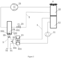
FIG. 1 shows a schematic diagram of a refrigeration system according to an embodiment of the present invention; and -
FIG. 2 shows a schematic diagram of a refrigeration system according to another embodiment of the present invention. - It is easy to understand that according to the technical solution of the present invention, without changing the essence of the present invention, those skilled in the art can propose multiple interchangeable structures and embodiments. Therefore, the following specific embodiments and drawings are only exemplary explanations of the technical solution of the present invention, and should not be regarded as the entirety of the present invention or as limitations or restrictions on the technical solution of the present invention. In particular, the scope of protection is defined by the appended claims.
- The orientation terms mentioned or possibly mentioned in the specification, such as up, down, left, right, front, back, front side, back side, top, bottom, etc., are defined relative to the structures shown in the accompanying drawings. They are relative concepts and may vary accordingly depending on their different positions and states of use. Therefore, these or other orientation terms should not be interpreted as restrictive terms.
- Referring first to
FIG. 1 , a refrigeration system according to an embodiment of the present invention is illustrated. The refrigeration system according to the embodiment of the present invention comprises: afirst circuit 1 comprising afirst evaporator 13, a second circuit 2 comprising asecond evaporator 24, and acoolant circuit 3. Although not shown, thecoolant circuit 3 comprises one or more loads, such as a data center server to be cooled. - In some embodiments, the
first circuit 1 is a natural cooling circuit, in which antifreeze may be used, where the antifreeze may include ethylene glycol, propylene glycol, or other suitable types of fluid. In some embodiments, thefirst circuit 1 comprises adrive pump 11, afirst condenser 12, and afirst evaporator 13. The fluid in thefirst circuit 1 exchanges heat with the environment (air) at thefirst condenser 12, and provides cooling capacity to the coolant in thecoolant circuit 3 at thefirst evaporator 13. In some embodiments, thefirst condenser 12 may be a circular tube plate fin heat exchanger. - In some embodiments, the second circuit 2 is a mechanical refrigeration circuit, which may include a
compressor 21, asecond condenser 22, athrottling device 23, and asecond evaporator 24. Conventional refrigerant such as R22 or R-134a circulates in the second circuit 2, and transfer the cooling capacity to the coolant in thecoolant circuit 3 at thesecond evaporator 24. In some embodiments, thefirst condenser 12 and thesecond condenser 22 of the refrigeration system can be integrated together, for example, integrated into the same outdoor unit. Besides, thefirst condenser 12 and thesecond condenser 22 can share thesame fan unit 4, thereby facilitating the installation of the system. - The
coolant circuit 3 passes through thefirst evaporator 13 and thesecond evaporator 24 in sequence. In other words, thefirst evaporator 13 and thesecond evaporator 24 are connected in series in thecoolant circuit 3, so that the coolant can exchange heat with the fluid in thefirst circuit 1 and the second circuit 2, respectively. Coolant commonly used in therefrigerant circuit 3 is, for example, water or salt water. Although not shown in the figure, thecoolant circuit 3 also includes a coolant drive pump and one or more loads. In addition, thecoolant circuit 3 further includes afirst bypass branch 341 in parallel with thefirst evaporator 13. Afirst control valve 33 is provided on thefirst bypass branch 341, where thefirst control valve 33 is used to control the on and off of thefirst bypass branch 341. For example, thefirst control valve 33 can be an electric water valve or other suitable type of valve that can be electrically controlled to connect or cut thefirst bypass branch 341. In some embodiments, thefirst bypass branch 341 can be directly connected between thecoolant inlet 331 and thecoolant outlet 332 of thefirst evaporator 13. -
FIG. 1 only illustrates a portion of thecoolant circuit 3, namely the portion between theinlet port 31 and theoutlet port 32. As a matter of fact, thecoolant circuit 3 also includes a coolant drive pump that drives the coolant to circulate in thecoolant circuit 3 and one or more loads to be cooled, such as data center servers. Specifically, the refrigeration system shown is commonly used in scenarios where cooling is required all year round, such as data centers, and the refrigeration system can operate in multiple modes. - In some embodiments, when the ambient temperature is relatively low, such as in winter or at night, the refrigeration system can operate in a first mode in which only the
first circuit 1 operates. At this point, thecompressor 21 in the second circuit can be turned off, and thedrive pump 11 in the first circuit is turned on, where thefirst circuit 1 alone can meet the refrigeration demand of the load. When the ambient temperature is relatively high, such as in summer or daytime, since thesecond condenser 12 may not be able to effectively dissipate heat to the environment, the refrigeration system can operate in a second mode in which only the second circuit 2 operates. At this point, thecompressor 21 in the second circuit can be turned on, and thedrive pump 11 in the first circuit is turned off. In addition, when the ambient temperature is moderate, such as in spring and autumn, the refrigeration system can operate in a third mode in which thefirst circuit 1 and the second circuit 2 both operate. In the third mode, thedrive pump 11 and thecompressor 21 are both turned on, while the coolant exchanges heat and is cooled in thefirst evaporator 13 and thesecond evaporator 24 in sequence. The refrigeration system can be configured with control devices to control the operating modes of the refrigeration system based on ambient temperature and other factors. - In the refrigeration system, especially when the
first evaporator 13 is a plate heat exchanger, it may have a relatively large flow resistance, which causes the energy consumption of the drive pump in thecoolant circuit 3 to increase, especially in the second mode when the first circuit is not in operation. Therefore, afirst bypass branch 341 is provided, on which afirst control valve 33 is arranged, so that thefirst evaporator 13 is bypassed when thefirst circuit 1 is not in operation. In some embodiments, thefirst control valve 33 is closed in the first mode and the third mode, and opened in the second mode, so that all the coolant passes through thefirst evaporator 13 in the first mode and the third mode, while most of the coolant passes through thebypass branch 341 without passing through thefirst evaporator 13 in the second mode. In some embodiments, in the second mode, thebypass branch 341 is configured so that at least 60% of the coolant passes through thebypass branch 341 without passing through thefirst evaporator 13. Optionally, in the second mode, at least 70% of the coolant passes through thebypass branch 341. Optionally, in the second mode, at least 80% of the coolant passes through thebypass branch 341. Optionally, in the second mode, at least 90% of the coolant passes through thebypass branch 341. It should be appreciated that although the flow resistance of thefirst evaporator 13 is relatively large, there will still be a portion of the coolant passing through it. By allowing most of the coolant to pass through thefirst bypass branch 341, the flow resistance of thecoolant circuit 3 in the second mode is greatly lowered, thereby reducing the energy consumption of the coolant drive pump on thecoolant circuit 3. Under some working conditions, such as in areas with warm climate all year round, in order to meet the cooling demand of the data center, i.e., water inlet temperature 18°C andwater outlet temperature 12°C, the refrigeration system operating under the second mode counts 50% or more of all working conditions in a year. By arranging thefirst bypass branch 341 and thefirst control valve 33, the energy consumption of the coolant drive pump on thecoolant circuit 3 can be reduced by more than 20%. - With continued reference to
FIG. 2 , a refrigeration system according to an alternative embodiment is shown. As to the refrigeration system according to the embodiment ofFIG. 2 , its operating concept is basically the same as that of the refrigeration system shown inFIG. 1 , except that a second bypass branch in parallel with thesecond evaporator 24 is further provided in the system, and asecond control valve 35 is arranged on the second bypass branch. In some embodiments, the refrigeration system is configured to allow thesecond control valve 35 to be closed in the second mode and the third mode, and to be opened in the first mode, so that most of the coolant does not pass through thesecond evaporator 24 in the first mode, thereby reducing the energy consumption of the coolant drive pump in the first mode. In some embodiments, the second bypass branch may be directly connected between the coolant inlet 351 and thecoolant outlet 352 of the second evaporator. Of course, in some embodiments, in the case where thesecond evaporator 24 is a flooded evaporator or a falling film evaporator, a second bypass branch and a second control valve may not be provided, as the flow resistance of thesecond evaporator 24 is relatively small in this case. In some embodiments, the first bypass branch and the first control valve, as well as the second bypass branch and the second control valve, can be selected to be configured based on the specific application environment of the refrigeration system, such as geographical location, annual temperature curve, and the like. - The refrigeration system according to the embodiments of the present invention has a smaller flow resistance in the mechanical refrigeration mode, thus effectively reducing the energy consumption of the coolant driving pump in the coolant circuit.
- The specific embodiments described above in the present invention are merely intended to describe the principles of the present invention more clearly, wherein various components are clearly shown or described to facilitate the understanding of the principles of the present invention. Those skilled in the art may, without departing from the scope of the present invention, make various modifications or changes to the present invention within the scope of the appended claims. Therefore, it should be understood that these modifications or changes falling within the scope of the appended claims should be included within the scope of patent protection of the present invention.
Claims (10)
- A refrigeration system, comprising:a first circuit, wherein the first circuit is a natural cooling circuit and comprises a first evaporator;a second circuit, wherein the second circuit is a mechanical refrigeration circuit and comprises a second evaporator; anda coolant circuit, wherein the coolant circuit passes through the first evaporator and the second evaporator in sequence, and the coolant circuit further comprises a first bypass branch in parallel with the first evaporator, where a first control valve is provided on the first bypass branch.
- The refrigeration system according to claim 1, wherein the first circuit comprises a drive pump, a first condenser, and the first evaporator, where fluid in the first circuit is antifreeze comprising ethylene glycol or propylene glycol.
- The refrigeration system according to claim 2, wherein the first evaporator is a plate heat exchanger.
- The refrigeration system according to any of claims 1-3, wherein the second circuit comprises a compressor, a second condenser, a second throttling device, and the second evaporator, where the second evaporator is a flooded evaporator or a falling film evaporator.
- The refrigeration system according to any of claims 1-3, wherein the first circuit comprises a first condenser, the second circuit comprises a second condenser, where the first condenser and the second condenser are integrated into one outdoor unit and share a fan unit.
- The refrigeration system according to any of claims 1-3, wherein the first bypass branch is connected between a coolant inlet and a coolant outlet of the first evaporator.
- The refrigeration system according to any of claims 1-3, wherein the refrigeration system is configured to operate in a first mode in which only the first circuit operates, a second mode in which only the second circuit operates, and a third mode in which the first circuit and the second circuit both operate.
- The refrigeration system according to claim 7, wherein the first control valve is closed in the first mode and the third mode, and opened in the second mode.
- The refrigeration system according to claim 7, wherein the coolant circuit further comprises a second bypass branch in parallel with the second evaporator, where a second control valve is provided on the second bypass branch, the second control valve is closed in the second mode and the third mode, and opened in the first mode, wherein the second bypass branch is connected between a coolant inlet and a coolant outlet of the second evaporator.
- The refrigeration system according to claim 7, wherein the coolant circuit further comprises a coolant drive pump and a load.
Applications Claiming Priority (1)
| Application Number | Priority Date | Filing Date | Title |
|---|---|---|---|
| CN202320060215.7U CN218977173U (en) | 2023-01-09 | 2023-01-09 | Cooling System |
Publications (1)
| Publication Number | Publication Date |
|---|---|
| EP4397924A1 true EP4397924A1 (en) | 2024-07-10 |
Family
ID=86168155
Family Applications (1)
| Application Number | Title | Priority Date | Filing Date |
|---|---|---|---|
| EP24151042.9A Pending EP4397924A1 (en) | 2023-01-09 | 2024-01-09 | Refrigeration system |
Country Status (3)
| Country | Link |
|---|---|
| US (1) | US12546514B2 (en) |
| EP (1) | EP4397924A1 (en) |
| CN (1) | CN218977173U (en) |
Citations (5)
| Publication number | Priority date | Publication date | Assignee | Title |
|---|---|---|---|---|
| US20140260376A1 (en) * | 2013-03-15 | 2014-09-18 | Johnson Controls Technology Company | Subcooling system with thermal storage |
| US20160363359A1 (en) * | 2015-06-10 | 2016-12-15 | Liebert Corporation | Cooling System With Direct Expansion And Pumped Refrigerant Economization Cooling |
| US20210262714A1 (en) * | 2018-08-17 | 2021-08-26 | Mitsubishi Electric Corporation | Cold water supply system |
| US11359847B2 (en) * | 2016-08-22 | 2022-06-14 | Johnson Controls Tyco IP Holdings LLP | Systems and methods for controlling a refrigeration system |
| US20220307748A1 (en) * | 2021-03-29 | 2022-09-29 | LGL France S.A.S. | Combined chiller and free cooling system for operation at low ambient temperature |
Family Cites Families (16)
| Publication number | Priority date | Publication date | Assignee | Title |
|---|---|---|---|---|
| US7185501B2 (en) * | 2004-12-16 | 2007-03-06 | General Electric Company | Cryogenic cooling system and method with backup cold storage device |
| US20100242532A1 (en) | 2009-03-24 | 2010-09-30 | Johnson Controls Technology Company | Free cooling refrigeration system |
| CN101769396B (en) | 2010-02-05 | 2012-05-30 | 清华大学 | Five-way valve for switching of natural cooling, refrigeration and heating modes |
| DE102012208174B4 (en) | 2012-05-16 | 2016-09-01 | Efficient Energy Gmbh | HEAT PUMP AND METHOD FOR PUMPING HEAT IN FREE COOLING MODE |
| US9581364B2 (en) | 2013-03-15 | 2017-02-28 | Johnson Controls Technology Company | Refrigeration system with free-cooling |
| US10718553B2 (en) | 2015-02-09 | 2020-07-21 | Carrier Corporation | Refrigeration and heating system |
| CN106032919B (en) | 2015-03-13 | 2019-09-24 | 阿里巴巴集团控股有限公司 | A kind of freezing water cooling system |
| RU2698856C2 (en) | 2015-07-22 | 2019-08-30 | Кэрриер Корпорейшн | Liquid system for combined natural cooling and mechanical cooling |
| US10739045B2 (en) | 2016-02-10 | 2020-08-11 | Johnson Controls Technology Company | Systems and methods for controlling a refrigeration system |
| WO2017160346A1 (en) | 2016-03-16 | 2017-09-21 | Inertech Ip Llc | System and methods utilizing fluid coolers and chillers to perform in-series heat rejection and trim cooling |
| CN109154461A (en) | 2016-05-25 | 2019-01-04 | 开利公司 | For freely cooling down air cooling and the water-cooled freezer unit of application |
| EP3760951B1 (en) | 2019-07-05 | 2022-04-27 | Carrier Corporation | Air handling unit and method for controlling such an air handling unit |
| US20230080007A1 (en) | 2020-02-26 | 2023-03-16 | Johnson Controls Tyco IP Holdings LLP | Free cooling system for hvac system |
| US11408621B2 (en) | 2020-12-15 | 2022-08-09 | Trane International Inc. | Systems and methods for controlling free cooling and integrated free cooling |
| US11953243B2 (en) | 2021-05-14 | 2024-04-09 | Tyco Fire & Security Gmbh | Mechanical-cooling, free-cooling, and hybrid-cooling operation of a chiller |
| EP4689512A1 (en) * | 2023-03-31 | 2026-02-11 | Tyco Fire & Security GmbH | Energy efficient free-cooling system and fluid for hvac&r system |
-
2023
- 2023-01-09 CN CN202320060215.7U patent/CN218977173U/en active Active
-
2024
- 2024-01-08 US US18/406,474 patent/US12546514B2/en active Active
- 2024-01-09 EP EP24151042.9A patent/EP4397924A1/en active Pending
Patent Citations (5)
| Publication number | Priority date | Publication date | Assignee | Title |
|---|---|---|---|---|
| US20140260376A1 (en) * | 2013-03-15 | 2014-09-18 | Johnson Controls Technology Company | Subcooling system with thermal storage |
| US20160363359A1 (en) * | 2015-06-10 | 2016-12-15 | Liebert Corporation | Cooling System With Direct Expansion And Pumped Refrigerant Economization Cooling |
| US11359847B2 (en) * | 2016-08-22 | 2022-06-14 | Johnson Controls Tyco IP Holdings LLP | Systems and methods for controlling a refrigeration system |
| US20210262714A1 (en) * | 2018-08-17 | 2021-08-26 | Mitsubishi Electric Corporation | Cold water supply system |
| US20220307748A1 (en) * | 2021-03-29 | 2022-09-29 | LGL France S.A.S. | Combined chiller and free cooling system for operation at low ambient temperature |
Also Published As
| Publication number | Publication date |
|---|---|
| US12546514B2 (en) | 2026-02-10 |
| CN218977173U (en) | 2023-05-05 |
| US20240230172A1 (en) | 2024-07-11 |
Similar Documents
| Publication | Publication Date | Title |
|---|---|---|
| CN111251823B (en) | Thermal management system and electric automobile | |
| US10401077B2 (en) | Chilled water cooling system | |
| EP3900964B1 (en) | Thermal management system | |
| EP3594031A1 (en) | Thermal management system | |
| US20230382181A1 (en) | Thermal management system and control method for same | |
| CN109094356B (en) | Electric automobile thermal management system | |
| EP4618238A1 (en) | Thermal management system and control method thereof | |
| US20120085512A1 (en) | Vehicle cooling system | |
| EP4224088A1 (en) | Thermal management system | |
| CN117445615A (en) | Heat pump system of electric automobile, electric automobile and heat control method of electric automobile | |
| US12415398B2 (en) | Thermal management system | |
| CN114179586A (en) | Electric automobile thermal management system | |
| EP3666565A1 (en) | Automotive air conditioning system | |
| CN221392928U (en) | Air conditioner and vehicle | |
| CN116803742B (en) | Charging gun wire heat exchange system | |
| US12546514B2 (en) | Refrigeration system | |
| CN112297757B (en) | Electric automobile thermal management system with concentrated circulation of cooling liquid and application method thereof | |
| CN214420170U (en) | Air conditioning system and automobile | |
| CN211468218U (en) | Pure electric vehicles and cooling system thereof | |
| US20230356559A1 (en) | Vehicle thermal management system of an electric vehicle and control method thereof | |
| EP4299343B1 (en) | Heat management system | |
| CN117812870A (en) | cooling system | |
| CN215216520U (en) | Air Conditioning Cooling Systems and Air Conditioners | |
| CN221505147U (en) | Driving plate assembly and air conditioning unit | |
| CN221417888U (en) | Heat pump system of electric automobile and electric automobile |
Legal Events
| Date | Code | Title | Description |
|---|---|---|---|
| PUAI | Public reference made under article 153(3) epc to a published international application that has entered the european phase |
Free format text: ORIGINAL CODE: 0009012 |
|
| STAA | Information on the status of an ep patent application or granted ep patent |
Free format text: STATUS: THE APPLICATION HAS BEEN PUBLISHED |
|
| AK | Designated contracting states |
Kind code of ref document: A1 Designated state(s): AL AT BE BG CH CY CZ DE DK EE ES FI FR GB GR HR HU IE IS IT LI LT LU LV MC ME MK MT NL NO PL PT RO RS SE SI SK SM TR |
|
| STAA | Information on the status of an ep patent application or granted ep patent |
Free format text: STATUS: REQUEST FOR EXAMINATION WAS MADE |
|
| 17P | Request for examination filed |
Effective date: 20250110 |
|
| STAA | Information on the status of an ep patent application or granted ep patent |
Free format text: STATUS: EXAMINATION IS IN PROGRESS |
|
| 17Q | First examination report despatched |
Effective date: 20260127 |