EP4397918A1 - Multi-split air conditioner control circuit, electrically controlled device, and air conditioner - Google Patents
Multi-split air conditioner control circuit, electrically controlled device, and air conditioner Download PDFInfo
- Publication number
- EP4397918A1 EP4397918A1 EP22862854.1A EP22862854A EP4397918A1 EP 4397918 A1 EP4397918 A1 EP 4397918A1 EP 22862854 A EP22862854 A EP 22862854A EP 4397918 A1 EP4397918 A1 EP 4397918A1
- Authority
- EP
- European Patent Office
- Prior art keywords
- power source
- circuit
- power
- air conditioner
- controller
- Prior art date
- Legal status (The legal status is an assumption and is not a legal conclusion. Google has not performed a legal analysis and makes no representation as to the accuracy of the status listed.)
- Pending
Links
- 230000004044 response Effects 0.000 claims description 14
- 238000005070 sampling Methods 0.000 claims description 12
- 239000003507 refrigerant Substances 0.000 claims description 10
- 239000003990 capacitor Substances 0.000 description 11
- 238000010586 diagram Methods 0.000 description 9
- 238000001816 cooling Methods 0.000 description 8
- 238000010438 heat treatment Methods 0.000 description 8
- 238000006243 chemical reaction Methods 0.000 description 3
- 230000009286 beneficial effect Effects 0.000 description 2
- 238000005265 energy consumption Methods 0.000 description 2
- 238000005516 engineering process Methods 0.000 description 2
- 238000000034 method Methods 0.000 description 2
- 230000008569 process Effects 0.000 description 2
- 206010034719 Personality change Diseases 0.000 description 1
- 238000004378 air conditioning Methods 0.000 description 1
- 230000008859 change Effects 0.000 description 1
- 230000008094 contradictory effect Effects 0.000 description 1
- 238000001514 detection method Methods 0.000 description 1
- 230000002452 interceptive effect Effects 0.000 description 1
Images

Classifications
-
- F—MECHANICAL ENGINEERING; LIGHTING; HEATING; WEAPONS; BLASTING
- F24—HEATING; RANGES; VENTILATING
- F24F—AIR-CONDITIONING; AIR-HUMIDIFICATION; VENTILATION; USE OF AIR CURRENTS FOR SCREENING
- F24F11/00—Control or safety arrangements
- F24F11/88—Electrical aspects, e.g. circuits
-
- F—MECHANICAL ENGINEERING; LIGHTING; HEATING; WEAPONS; BLASTING
- F24—HEATING; RANGES; VENTILATING
- F24F—AIR-CONDITIONING; AIR-HUMIDIFICATION; VENTILATION; USE OF AIR CURRENTS FOR SCREENING
- F24F11/00—Control or safety arrangements
- F24F11/30—Control or safety arrangements for purposes related to the operation of the system, e.g. for safety or monitoring
- F24F11/46—Improving electric energy efficiency or saving
-
- F—MECHANICAL ENGINEERING; LIGHTING; HEATING; WEAPONS; BLASTING
- F24—HEATING; RANGES; VENTILATING
- F24F—AIR-CONDITIONING; AIR-HUMIDIFICATION; VENTILATION; USE OF AIR CURRENTS FOR SCREENING
- F24F11/00—Control or safety arrangements
- F24F11/62—Control or safety arrangements characterised by the type of control or by internal processing, e.g. using fuzzy logic, adaptive control or estimation of values
- F24F11/63—Electronic processing
- F24F11/65—Electronic processing for selecting an operating mode
-
- F—MECHANICAL ENGINEERING; LIGHTING; HEATING; WEAPONS; BLASTING
- F24—HEATING; RANGES; VENTILATING
- F24F—AIR-CONDITIONING; AIR-HUMIDIFICATION; VENTILATION; USE OF AIR CURRENTS FOR SCREENING
- F24F11/00—Control or safety arrangements
- F24F11/89—Arrangement or mounting of control or safety devices
Definitions
- the present application relates to the technical field of air conditioner, and in particular to a variable refrigerant flow (VRF) air conditioner control circuit, an electronic control device and an air conditioner.
- VRF variable refrigerant flow
- VRF variable refrigerant flow
- the main objective of the present application is to provide a variable refrigerant flow (VRF) air conditioner control circuit, an electronic control device and an air conditioner, aiming to solve the technical problem of high energy consumption in the outdoor unit of the VRF air conditioners in the related art.
- VRF variable refrigerant flow
- the present application provides a VRF air conditioner control circuit, which is applied to the outdoor unit of the VRF air conditioner.
- the VRF air conditioner control circuit includes: a power input terminal, a wake-up circuit, a controller and a first switch.
- the power input terminal is configured to access a first power source.
- the wake-up circuit is configured to provide a second power source to the controller in response to receiving a working signal sent by an indoor unit of the VRF air conditioner.
- the controller is configured to control the first switch to switch from an off state to an on state to receive the first power source in response to receiving the working signal and the second power source.
- the controller is respectively connected to the power input terminal and the wake-up circuit, and the first switch is provided between the controller and the power input terminal.
- the wake-up circuit includes a power input circuit and a power output circuit connected to each other, and the power input circuit is connected to a power supply circuit of the indoor unit.
- the power input circuit is configured to use the third power source as the working signal in response to detecting the third power source provided by the power supply circuit.
- the wake-up circuit further includes a second switch provided between the power output circuit and the controller.
- the controller is further configured to control the first switch from an on state to an off state in response to not receiving the working signal.
- the first switch is a relay
- a control end of the relay is connected to a control end of the controller
- a first contact point of the relay is connected to the power input terminal
- a second contact point of the relay is connected to a power supply terminal of the controller.
- a switch is provided between the controller in the outdoor unit and the first power source as the working power source.
- the controller determines the required working state of the outdoor unit according to the working signals sent by each indoor unit to control the power-on or power-down of the controller, thereby causing the outdoor unit to switch between the low power consumption mode and the working mode, realizing the low power consumption mode configuration for the outdoor unit in the VRF air conditioner, and reducing the power consumption of the outdoor unit.
- the VRF air conditioner control circuit in the embodiment is provided inside the outdoor unit 50.
- the controller 30 refers to the controller inside the outdoor unit 50.
- the controller 30 can be combined with a corresponding drive circuit to form a driver for driving the load.
- the load may include devices such as compressors, fans, electronic expansion valves, etc.
- the drive circuits corresponding to various types of loads already have mature circuit structures, which will not be described again in the embodiment.
- the embodiment mainly takes the automatic control of the outdoor unit 50 as an example for description.
- the controller 30 needs to control the state of the first switch 40 according to the working state of the indoor unit 60.
- the outdoor unit 50 needs to provide corresponding cooling capacity or heating capacity. Therefore, the outdoor unit 50 can usually enter the low power consumption mode only when there is no demand for cooling capacity or heating capacity from the indoor units 60.
- the wake-up circuit 20 provides the second power source to the controller 30 as the wake-up power source to power the controller 30.
- the wake-up circuit 20 can be provided with a built-in power source, and when receiving a working signal, the built-in power source is converted into a second power source for output.
- the wake-up circuit 20 can also be connected to an external power source, and when receiving a working signal, the external power source is converted into a second power source for output.
- the controller 30 also needs to receive the working signal. If the outdoor unit is in the low power consumption mode, the second power source serves as the working power source to enable the controller 30 to operate normally. At this time, if the controller 30 receives the working signal, the first switch 40 is controlled to switch from the off state to the on state, so as to receive the first power source and restore the normal power source, thereby causing the outdoor unit 50 to wake up from the low power consumption mode and enter the working mode.
- a VRF air conditioner control circuit is formed by providing the power input terminal 10, the wake-up circuit 20, the controller 30 and the first switch 40 on the outdoor unit 50 of the VRF air conditioner.
- the power input terminal 10 is configured to access the first power source; the wake-up circuit 20 provides the second power source to the controller 30 when receiving the working signal sent by the indoor unit 60 of the VRF air conditioner.
- the controller 30 is configured to control the first switch 40 to switch from an off state to an on state to receive the first power source when receiving the working signal and the second power source.
- a switch is provided between the controller 30 in the outdoor unit 50 and the first power source as the working power source.
- the controller 30 determines the required working state of the outdoor unit 50 according to the working signals sent by each indoor unit 60, so as to control the power-on or power-down of the controller 30, thereby switching the outdoor unit 50 between the low power consumption mode and the working mode, realizing the configuration of the low power consumption mode for the outdoor unit 50 in the VRF air conditioner, and reducing power consumption of the outdoor unit 50.
- FIG. 3 is a schematic structural diagram of the VRF air conditioner control circuit according to a second embodiment of the present application. Based on the above first embodiment, the present application provides a second embodiment of a VRF air conditioner control circuit.
- the power supply circuit is configured to provide a third power source to power the indoor unit 60 when it is in a power supply state.
- the power output circuit 202 is configured to convert the third power source into the second power source and transmit the second power source to the controller 30.
- the third power source as the power source in the indoor unit 60 is configured as the working signal.
- the power supply circuit is configured to convert the independent power source corresponding to each indoor unit 60 into a power source to drive the load in each indoor unit 60 to operate.
- the third power source can be the power source.
- the working state of the indoor unit 60 can be determined by determining whether the power supply circuit of the indoor unit provides power source.
- the power supply circuit has a mature circuit structure, which will not be described in detail in the embodiment.
- the power supply circuit of each indoor unit 60 is also connected to the power input circuit 201 in the outdoor unit 50.
- the power supply circuit supplies power to the load in the indoor unit 60, it further provides a third power source to the power input circuit 201 at the same time.
- the power supply circuit stops supplying power to the load in the indoor unit 60, it also stops supplying the third power source to the power input circuit 201.
- the third power source is actually the power source for the load in the indoor unit 60, its amplitude is usually high. In order to avoid damage to the controller 30, the third power source further needs to be performed with process such as step-down, etc.
- the third power source can be 12V or 24V, and 3V or 5V
- the third power source is usually alternating current (AC) power
- the second power source is usually DC power, so the power output circuit 202 also needs to rectify the third power source.
- the third power source is also converted into the second power source at the same time to serve as the wake-up power source for the controller 30.
- the wake-up circuit 20 also includes a second switch 203.
- the second switch 203 is provided between the power output circuit 202 and the controller 30.
- the controller 30 is further configured to control the second switch 203 to switch from an on state to an off state when receiving the first power source.
- the controller 30 can operate normally after receiving the first power source. At this time, it is no longer necessary to wake up the power source.
- the circuit between the power output circuit 202 and the controller 30 can be cut off so that the controller 30 no longer needs to receive a second power source, thereby further saving energy.
- the second switch 203 is a normally closed switch, which may be a relay. After receiving the first power source, the controller 30 applies current to the relay coil of the second switch 203, thereby switching the second switch 203 from the on state to the off state. When the controller 30 receives the first power source, the current on the relay coil of the switch 203 disappears, and the second switch 203 returns to the on state.
- the second switch 203 can also be other types of switches, which is not limited in the embodiment.
- FIG. 4 is a schematic circuit principle diagram of a wake-up circuit according to an embodiment of the present application.
- the embodiment further provides a circuit principle diagram of the wake-up circuit 20.
- the power input circuit 201 includes a first resistor R1, a second resistor, a first capacitor C1, a second capacitor C2 and a rectifier B.
- the first input terminal of the rectifier B is connected to the first terminal of the first resistor R1 and the first terminal of the first capacitor C1 respectively.
- the second terminal of the first capacitor C1 is connected to the second input terminal of the rectifier B.
- the first input terminal and the second input terminal of the rectifier B are configured to access the AC power source.
- the first output terminal of the rectifier B is connected to the first terminal of the second resistor R2 and the first terminal of the second capacitor C2 respectively.
- the second terminal of the second capacitor C2 is connected to the second output terminal of the rectifier B.
- the second terminal of the rectifier B is connected to ground, and the second terminal of the second resistor R2 is connected to the power output circuit 202.
- the power input circuit 201 is configured to access AC current, perform rectification, and transmit DC power to the power output circuit 202.
- the VRF air conditioner control circuit further includes a sampling circuit 70.
- the sampling circuit 70 is respectively connected to the power supply circuit and the controller 30.
- the sampling circuit 70 is configured to obtain the voltage signal corresponding to the third power source, and transmit the voltage signal to the controller 30 as the working signal.
- the sampling circuit 70 may first sample the third power source to obtain the DC power, and then the step-down processing is performed on the DC power, or a lower voltage signal is output to the controller 30.
- the sampling circuit 70 can also obtain the voltage signal from the output end of the power input circuit 201.
- the VRF air conditioner control circuit further includes a power source circuit 80 provided between the first switch 40 and the controller 30.
- the power source circuit 80 is configured to convert the first power source into a fourth power source adapted to the controller 30, and transmit the fourth power to the controller 30.
- the VRF air conditioner control circuit further includes a load power supply circuit 90 connected to the power source circuit 80.
- the power source circuit 80 is further configured to convert the first power source into a fifth power source adapted to the load of the outdoor unit 50, and transmit the fifth power source to the load power supply circuit 90.
- the load power supply circuit 90 is configured to drive the load according to the fifth power source.
- the wake-up circuit 20 includes a power input circuit 201 and a power output circuit 202 connected to the power supply circuit of the indoor unit 60.
- the power input circuit 201 detects the third power source provided by the power supply circuit, the third power source is used as the working signal.
- the power output circuit 202 converts the third power into a second power and transmits the second power to the controller 30.
- the power supply source of the indoor unit 60 is multiplexed, and the power supply source is used as the working signal. If the power input circuit 201 receives the power source, it means that the indoor unit 60 is in the working mode, and the outdoor unit 50 also needs to enter the working mode.
- the third power source is converted to obtain the second power source, which is configured as the driving power source of the controller 30 so that the controller 30 can operate normally, thereby causing the outdoor unit 50 to wake up from the low-power consumption mode.
- the present application further provides an air conditioner.
- the air conditioner includes the above-mentioned electronic control device; or includes the above-mentioned VRF air conditioner control circuit.
- the specific structure of the electronic control device or the VRF air conditioner control circuit refers to the above-mentioned embodiments. Since the air conditioner can adopt the technical solutions of all the above-mentioned embodiments, it at least has the beneficial effects brought by the technical solutions of the above-mentioned embodiments, which will not be repeated here.
Landscapes
- Engineering & Computer Science (AREA)
- Chemical & Material Sciences (AREA)
- Combustion & Propulsion (AREA)
- Mechanical Engineering (AREA)
- General Engineering & Computer Science (AREA)
- Signal Processing (AREA)
- Physics & Mathematics (AREA)
- Fuzzy Systems (AREA)
- Mathematical Physics (AREA)
- Air Conditioning Control Device (AREA)
Abstract
Description
- The present application claims priority to
Chinese Patent Application No. 202111019328.4, filed on August 31, 2021 - The present application relates to the technical field of air conditioner, and in particular to a variable refrigerant flow (VRF) air conditioner control circuit, an electronic control device and an air conditioner.
- At present, air conditioners are often configured with a low power consumption mode in order to save energy efficiency. When the indoor unit is in standby mode, the outdoor unit loses power and enters standby mode. However, this mode cannot be applied to the variable refrigerant flow (VRF) air conditioner system. When the outdoor unit drives a plurality of indoor units, the power source of the outdoor unit cannot be controlled according to the operating status of a single indoor unit. Therefore, in a VRF system, the outdoor unit is always in a power-on state, resulting in increased energy consumption.
- The main objective of the present application is to provide a variable refrigerant flow (VRF) air conditioner control circuit, an electronic control device and an air conditioner, aiming to solve the technical problem of high energy consumption in the outdoor unit of the VRF air conditioners in the related art.
- In order to solve the above objective, the present application provides a VRF air conditioner control circuit, which is applied to the outdoor unit of the VRF air conditioner. The VRF air conditioner control circuit includes: a power input terminal, a wake-up circuit, a controller and a first switch.
- In an embodiment, the power input terminal is configured to access a first power source.
- In an embodiment, the wake-up circuit is configured to provide a second power source to the controller in response to receiving a working signal sent by an indoor unit of the VRF air conditioner.
- In an embodiment, the controller is configured to control the first switch to switch from an off state to an on state to receive the first power source in response to receiving the working signal and the second power source.
- In an embodiment, the controller is respectively connected to the power input terminal and the wake-up circuit, and the first switch is provided between the controller and the power input terminal.
- In an embodiment, the wake-up circuit includes a power input circuit and a power output circuit connected to each other, and the power input circuit is connected to a power supply circuit of the indoor unit.
- In an embodiment, the power supply circuit is configured to provide a third power source to power the indoor unit in response to being in a power supply state.
- In an embodiment, the power input circuit is configured to use the third power source as the working signal in response to detecting the third power source provided by the power supply circuit.
- In an embodiment, the power output circuit is configured to convert the third power source into the second power source and transmit the second power source to the controller.
- In an embodiment, the wake-up circuit further includes a second switch provided between the power output circuit and the controller.
- In an embodiment, the controller is further configured to control the second switch to switch from an on state to an off state in response to receiving the first power source.
- In an embodiment, the VRF air conditioner control circuit further includes a sampling circuit, the sampling circuit is respectively connected to the power supply circuit and the controller.
- In an embodiment, the sampling circuit is configured to obtain a voltage signal corresponding to the third power source, and transmit the voltage signal to the controller as the working signal.
- In an embodiment, the VRF air conditioner control circuit further includes a power source circuit provided between the first switch and the controller.
- In an embodiment, the power source circuit is configured to convert the first power source into a fourth power source adapted to the controller, and transmit the fourth power source to the controller.
- In an embodiment, the VRF air conditioner control circuit further includes a load power supply circuit connected to the power source circuit.
- In an embodiment, the power source circuit is further configured to convert the first power source into a fifth power source adapted to a load of the outdoor unit, and transmit the fifth power source to the load power supply circuit.
- In an embodiment, the load power supply circuit is configured to drive the load according to the fifth power source.
- In an embodiment, the controller is further configured to control the first switch from an on state to an off state in response to not receiving the working signal.
- In an embodiment, the first switch is a relay, a control end of the relay is connected to a control end of the controller, a first contact point of the relay is connected to the power input terminal, and a second contact point of the relay is connected to a power supply terminal of the controller.
- In order to achieve the above object, the present application further provides an electronic control device, which includes the above-mentioned VRF air conditioner control circuit.
- In order to achieve the above object, the present application further provides an air conditioner. The air conditioner includes the above-mentioned electronic control device; or includes the above-mentioned VRF air conditioner control circuit.
- In the present application, a VRF air conditioner control circuit is formed by providing a power input terminal, a wake-up circuit, a controller and a first switch on the outdoor unit of the VRF air conditioner. The controller is connected to the power input terminal and the wake-up circuit respectively, and the first switch is provided between the controller and the power input terminal; the power input terminal is used to access the first power source; the wake-up circuit is used to receive the VRF connection When the indoor unit of the air conditioner sends a working signal, the second power source is provided to the controller; the controller is used to control the first switch to switch from an off state to an on state when receiving the working signal and the second power source to receive the second power source. A power source. In the present application, a switch is provided between the controller in the outdoor unit and the first power source as the working power source. The controller determines the required working state of the outdoor unit according to the working signals sent by each indoor unit to control the power-on or power-down of the controller, thereby causing the outdoor unit to switch between the low power consumption mode and the working mode, realizing the low power consumption mode configuration for the outdoor unit in the VRF air conditioner, and reducing the power consumption of the outdoor unit.
- In order to more clearly illustrate the technical solutions in the embodiments of the present application or in the related art, drawings used in the embodiments or in the related art will be briefly described below. Obviously, the drawings in the following description are only some embodiments of the present application. It will be apparent to those skilled in the art that other figures can be obtained according to the structures shown in the drawings without creative work.
-
FIG. 1 is a schematic structural diagram of a variable refrigerant flow (VRF) air conditioner control circuit according to a first embodiment of the present application. -
FIG. 2 is a schematic structural diagram of a VRF air conditioner according to an embodiment of the present application. -
FIG. 3 is a schematic structural diagram of the VRF air conditioner control circuit according to a second embodiment of the present application. -
FIG. 4 is a schematic circuit principle diagram of a wake-up circuit according to an embodiment of the present application. - Description of reference signs:
Reference sign Name Reference sign Name 10 power input terminal 80 power source circuit 20 wake- up circuit 90 load power supply circuit 201 power input circuit R1∼R3 first to third resistors 202 district current (DC) power source C1∼C3 first to third capacitors 203 control signal L1 first inductor 30 controller B rectifier 40 first switch T Zener diode 50 outdoor unit K electronic switch 60 indoor unit IC power chip 70 sampling circuit - The realization of the objective, functional characteristics, and advantages of the present application are further described with reference to the accompanying drawings.
- It should be understood that the embodiments described here are only used to explain the present application and are not intended to limit the present application.
- The technical solutions of the embodiments of the present application will be described in more detail below with reference to the accompanying drawings. It is obvious that the embodiments to be described are only some rather than all of the embodiments of the present application. All other embodiments obtained by persons skilled in the art based on the embodiments of the present application without creative efforts shall fall within the scope of the present application.
- It should be noted that all of the directional instructions in the embodiments of the present application (such as, up, down, left, right, front, rear.....) are only used to explain the relative position relationship and movement of each component under a specific attitude (as shown in the drawings), if the specific attitude changes, the directional instructions will change correspondingly.
- Besides, the descriptions in the present application that refer to "first," "second," etc. are only for descriptive purposes and are not to be interpreted as indicating or implying relative importance or to implicitly indicate the number of technical features indicated. Thus, a feature defined as "first" or "second" may explicitly or implicitly include at least one of the features. In addition, technical solutions between the embodiments can be combined with each other, but must be based on the realization of the technical solutions by those skilled in the art, and when the technical solutions are contradictory to each other or cannot be realized, the technical solutions should be considered that the combination does not exist, and the technical solutions are not fallen within the protection scope claimed in the present application.
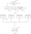
- As shown in
FIG. 1, FIG. 1 is a schematic structural diagram of a variable refrigerant flow (VRF) air conditioner control circuit according to a first embodiment of the present application. The present application provides a first embodiment of the VRF air conditioner control circuit. - In the first embodiment, the VRF air conditioner control circuit is applied to the
outdoor unit 50 of the VRF air conditioner. The VRF air conditioner control circuit includes: apower input terminal 10, a wake-up circuit 20, acontroller 30 and afirst switch 40. Thecontroller 30 is respectively connected to thepower input terminal 10 and the wake-up circuit 20, and thefirst switch 40 is provided between thecontroller 30 and thepower input terminal 10. - The
power input terminal 10 is configured to access a first power source. - The wake-
up circuit 20 is configured to provide a second power source to thecontroller 30 in response to receiving a working signal sent by anindoor unit 60 of the VRF air conditioner. - The
controller 30 is configured to control thefirst switch 40 to switch from an off state to an on state to receive the first power source in response to receiving the working signal and the second power source. - As shown in
FIG. 2, FIG. 2 is a schematic structural diagram of a VRF air conditioner according to an embodiment of the present application. The VRF air conditioner refers to an air-conditioning system in which oneoutdoor unit 50 drives the plurality ofindoor units 60. The refrigerant output from theoutdoor unit 50 is transported to eachindoor unit 60 through a diverter element, so that eachindoor unit 60 can complete the heat exchange operation. Usually, theoutdoor unit 50 and eachindoor unit 60 are equipped with independent power sources to provide power for the drivers and loads inside theoutdoor unit 50 or eachindoor unit 60. When eachindoor unit 60 is in the non-working mode, the corresponding independent power source is disconnected, so that each internal load is in a power-down state, and the entire machine is in a low power consumption mode to save energy. - It should be understood that, the VRF air conditioner control circuit in the embodiment is provided inside the
outdoor unit 50. Thecontroller 30 refers to the controller inside theoutdoor unit 50. Thecontroller 30 can be combined with a corresponding drive circuit to form a driver for driving the load. The load may include devices such as compressors, fans, electronic expansion valves, etc. The drive circuits corresponding to various types of loads already have mature circuit structures, which will not be described again in the embodiment. - It should be noted that the first power source refers to an independent power source configured with the
outdoor unit 50, which can be the power source provided by a power adapter and other device, or the mains power. When theoutdoor unit 50 is in the working mode, each internal unit is powered by the first power source. In the embodiment, a low power consumption mode is configured on theoutdoor unit 50, and afirst switch 40 is provided between thecontroller 30 and thepower input terminal 10. When theoutdoor unit 50 is in the working mode, thefirst switch 40 is in an on state, and thecontroller 30 can receive the first power source. When theoutdoor unit 50 is in the low power consumption mode, thefirst switch 40 is in an off state, and thecontroller 30 cannot receive the first power source and cannot execute the corresponding control logic, and theoutdoor unit 50 is in the low power consumption mode. The state of thefirst switch 40 can be controlled by thecontroller 30. Thefirst switch 40 can also be provided with interactive components to facilitate the user to switch the working state of theoutdoor unit 50. - The embodiment mainly takes the automatic control of the
outdoor unit 50 as an example for description. During specific implementation, thecontroller 30 needs to control the state of thefirst switch 40 according to the working state of theindoor unit 60. In order to ensure the normal operation of theindoor unit 60, when theindoor unit 60 has a demand for cooling capacity or heating capacity, theoutdoor unit 50 needs to provide corresponding cooling capacity or heating capacity. Therefore, theoutdoor unit 50 can usually enter the low power consumption mode only when there is no demand for cooling capacity or heating capacity from theindoor units 60. - In the embodiment, the working signal can be configured to determine whether the
indoor unit 60 is in the working mode and whether there is a demand for cooling capacity or heating capacity, that is, to determine whether theoutdoor unit 50 needs to enter the working mode. If theoutdoor unit 50 receives the working signal, it determines that it needs to enter the working mode to provide theindoor unit 60 with corresponding cooling capacity or heating capacity. If theoutdoor unit 50 does not receive the working signal, it determines that it does not need to enter the working mode. Theoutdoor unit 50 entering the working mode means that the compressor and other devices are powered on and operating, and the refrigerant is transmitted to theindoor unit 60 to perform cooling or heating operations. - In an embodiment, each
indoor unit 60 can communicate with theoutdoor unit 50 respectively. When entering the working mode, eachindoor unit 60 sends a working signal to theoutdoor unit 50. When the wake-up circuit 20 receives the working signal sent by any one ofindoor units 60, a second power source is provided to thecontroller 30. - It should be noted that when the
outdoor unit 50 is in the low power consumption mode, thecontroller 30 cannot receive the first power source. In order to make thecontroller 30 work normally, the wake-up circuit 20 provides the second power source to thecontroller 30 as the wake-up power source to power thecontroller 30. In an embodiment, the wake-up circuit 20 can be provided with a built-in power source, and when receiving a working signal, the built-in power source is converted into a second power source for output. The wake-up circuit 20 can also be connected to an external power source, and when receiving a working signal, the external power source is converted into a second power source for output. - In addition, in order to facilitate the determination of the working state of the
indoor unit 60, thecontroller 30 also needs to receive the working signal. If the outdoor unit is in the low power consumption mode, the second power source serves as the working power source to enable thecontroller 30 to operate normally. At this time, if thecontroller 30 receives the working signal, thefirst switch 40 is controlled to switch from the off state to the on state, so as to receive the first power source and restore the normal power source, thereby causing theoutdoor unit 50 to wake up from the low power consumption mode and enter the working mode. - In an embodiment, the
controller 30 is further configured to control thefirst switch 40 to switch from the on state to the off state when no working signal is received. - It should be noted that when the
indoor unit 60 is in the working mode, it will continue to send working signals to theoutdoor unit 50. The presence or absence of the working signal indicates whether theindoor unit 60 is in the working mode. For example, the working state of the control unit in theindoor unit 60 is detected in real time, and when the control unit is in the working mode, a working signal is generated and sent to theoutdoor unit 50. When the working signal is received by the signal receiving unit of theoutdoor unit 50, the working signal is transmitted to the wake-up circuit 20 and thecontroller 30. Therefore, when theoutdoor unit 50 is in the working mode, if thecontroller 30 does not receive the working signal sent by any one of theindoor units 60, it means that all theindoor units 60 are not in the working mode, and theoutdoor unit 50 does not need to provide corresponding cooling capacity or heating capacity. At this time, thecontroller 30 can control the first switch to switch from the on state to the off state, so that theoutdoor unit 50 enters the low power consumption mode. - In an embodiment, the
first switch 40 can be a relay, the control end of the relay is connected to the control end of thecontroller 30, the second contact point of the relay is connected to thepower input terminal 10, and the first contact point of the relay is connected to the power supply terminal of thecontroller 30. - It can be understood that the control end of the relay can be the connection end of the relay coil, and the first contact point and the second contact point of the relay are closed when the relay coil is energized, and are opened when the relay coil is not energized. The
first switch 40 is a normally open switch, and the control end of thecontroller 30 is configured to output control power source. When thecontroller 30 receives the working signal and the second power source, the control power source is output to energize the relay coil, thereby conduct a loop between theinput terminal 10 and the power supply terminal of thecontroller 30 to receive the first power source. Of course, thefirst switch 40 can also use other types of switching devices, which is not limited in the embodiment. - In the first embodiment, a VRF air conditioner control circuit is formed by providing the
power input terminal 10, the wake-up circuit 20, thecontroller 30 and thefirst switch 40 on theoutdoor unit 50 of the VRF air conditioner. Thepower input terminal 10 is configured to access the first power source; the wake-up circuit 20 provides the second power source to thecontroller 30 when receiving the working signal sent by theindoor unit 60 of the VRF air conditioner. Thecontroller 30 is configured to control thefirst switch 40 to switch from an off state to an on state to receive the first power source when receiving the working signal and the second power source. In the embodiment, a switch is provided between thecontroller 30 in theoutdoor unit 50 and the first power source as the working power source. Thecontroller 30 determines the required working state of theoutdoor unit 50 according to the working signals sent by eachindoor unit 60, so as to control the power-on or power-down of thecontroller 30, thereby switching theoutdoor unit 50 between the low power consumption mode and the working mode, realizing the configuration of the low power consumption mode for theoutdoor unit 50 in the VRF air conditioner, and reducing power consumption of theoutdoor unit 50. - As shown in
FIG. 3, FIG. 3 is a schematic structural diagram of the VRF air conditioner control circuit according to a second embodiment of the present application. Based on the above first embodiment, the present application provides a second embodiment of a VRF air conditioner control circuit. - In the second embodiment, the wake-
up circuit 20 includes apower input circuit 201 and apower output circuit 202 connected to each other. Thepower input circuit 201 is connected to the power supply circuit of theindoor unit 60. - The power supply circuit is configured to provide a third power source to power the
indoor unit 60 when it is in a power supply state. - The
power input circuit 201 is configured to use the third power source as a working signal when detecting the third power source provided by the power supply circuit. - The
power output circuit 202 is configured to convert the third power source into the second power source and transmit the second power source to thecontroller 30. - In order to facilitate detection of the working state of each
indoor unit 60 and thereby facilitate control of the working state of theoutdoor unit 50, in the embodiment, the third power source as the power source in theindoor unit 60 is configured as the working signal. The power supply circuit is configured to convert the independent power source corresponding to eachindoor unit 60 into a power source to drive the load in eachindoor unit 60 to operate. The third power source can be the power source. - It can be understood that if the load in the
indoor unit 60 is in the powered-on state, it means that theindoor unit 60 is in the working mode, that is, it has corresponding cooling capacity or heating capacity demands. Therefore, the working state of theindoor unit 60 can be determined by determining whether the power supply circuit of the indoor unit provides power source. The power supply circuit has a mature circuit structure, which will not be described in detail in the embodiment. - In an embodiment, the power supply circuit of each
indoor unit 60 is also connected to thepower input circuit 201 in theoutdoor unit 50. When the power supply circuit supplies power to the load in theindoor unit 60, it further provides a third power source to thepower input circuit 201 at the same time. When the power supply circuit stops supplying power to the load in theindoor unit 60, it also stops supplying the third power source to thepower input circuit 201. - Since the third power source is actually the power source for the load in the
indoor unit 60, its amplitude is usually high. In order to avoid damage to thecontroller 30, the third power source further needs to be performed with process such as step-down, etc. Usually the third power source can be 12V or 24V, and 3V or 5V In addition, the third power source is usually alternating current (AC) power, and the second power source is usually DC power, so thepower output circuit 202 also needs to rectify the third power source. - In an embodiment, the third power source is also converted into the second power source at the same time to serve as the wake-up power source for the
controller 30. By multiplexing the power source of theindoor unit 60, the accuracy of detecting the status of the indoor unit is improved, and the wake-up circuit 20 is also simplified, making it easier to implement. - In an embodiment, the wake-
up circuit 20 also includes asecond switch 203. Thesecond switch 203 is provided between thepower output circuit 202 and thecontroller 30. Thecontroller 30 is further configured to control thesecond switch 203 to switch from an on state to an off state when receiving the first power source. - It can be understood that the
controller 30 can operate normally after receiving the first power source. At this time, it is no longer necessary to wake up the power source. The circuit between thepower output circuit 202 and thecontroller 30 can be cut off so that thecontroller 30 no longer needs to receive a second power source, thereby further saving energy. In an embodiment, thesecond switch 203 is a normally closed switch, which may be a relay. After receiving the first power source, thecontroller 30 applies current to the relay coil of thesecond switch 203, thereby switching thesecond switch 203 from the on state to the off state. When thecontroller 30 receives the first power source, the current on the relay coil of theswitch 203 disappears, and thesecond switch 203 returns to the on state. Of course, thesecond switch 203 can also be other types of switches, which is not limited in the embodiment. - As shown in
FIG. 4, FIG. 4 is a schematic circuit principle diagram of a wake-up circuit according to an embodiment of the present application. As an example, the embodiment further provides a circuit principle diagram of the wake-up circuit 20. Thepower input circuit 201 includes a first resistor R1, a second resistor, a first capacitor C1, a second capacitor C2 and a rectifier B. The first input terminal of the rectifier B is connected to the first terminal of the first resistor R1 and the first terminal of the first capacitor C1 respectively. The second terminal of the first capacitor C1 is connected to the second input terminal of the rectifier B. The first input terminal and the second input terminal of the rectifier B are configured to access the AC power source. The first output terminal of the rectifier B is connected to the first terminal of the second resistor R2 and the first terminal of the second capacitor C2 respectively. The second terminal of the second capacitor C2 is connected to the second output terminal of the rectifier B. The second terminal of the rectifier B is connected to ground, and the second terminal of the second resistor R2 is connected to thepower output circuit 202. Thepower input circuit 201 is configured to access AC current, perform rectification, and transmit DC power to thepower output circuit 202. - The
power output circuit 202 includes a power chip IC, a first inductor L1, a third capacitor C3, a third resistor R3 and a Zener diode T. Thesecond switch 203 includes an electronic switch K, the control end of thesecond switch 203 is connected to thecontroller 30. The input end of the power chip IC is connected to the second end of the second resistor, the output end of the power chip IC is connected to the first end of the first inductor L1 and the cathode of the Zener diode T respectively. The second end of the first inductor L1 is respectively connected to the first terminal of the third resistor R3, the first terminal of the third capacitor C3 and the first terminal of the electronic switch K. The anode of the Zener diode T, the second terminal of the third resistor R3 and the second terminal of the third capacitor C3 are all grounded. The power chip IC is configured to perform voltage conversion on the input DC power, and output the power through a filter circuit composed of the first inductor L1, a third capacitor C3 and a third resistor R3. Of course, the wake-up circuit 20 is other circuits that realize similar functions, and the embodiment is not limited thereto. - It should be noted that the power chip IC can further communicate with the
controller 30. After receiving the first power source, thecontroller 30 sends a shutdown signal to the power chip IC. After receiving the shutdown signal, the power chip IC stops outputting power. At this time, thesecond switch 203 does not need to be provided in the wake-up circuit 20, and automatic cut-off can also be realized. - In addition, in order to further avoid damage to the
controller 30, the VRF air conditioner control circuit further includes asampling circuit 70. Thesampling circuit 70 is respectively connected to the power supply circuit and thecontroller 30. Thesampling circuit 70 is configured to obtain the voltage signal corresponding to the third power source, and transmit the voltage signal to thecontroller 30 as the working signal. - It should be noted that since the voltage of the third power source is high and is AC power, directly inputting it into the port of the
controller 30 may easily cause damage to thecontroller 30. Therefore, thesampling circuit 70 may first sample the third power source to obtain the DC power, and then the step-down processing is performed on the DC power, or a lower voltage signal is output to thecontroller 30. In an embodiment, since thepower input circuit 201 rectifies the third power source, thesampling circuit 70 can also obtain the voltage signal from the output end of thepower input circuit 201. - It can be understood that the
controller 30 can determine the working state of theindoor unit 60 according to the voltage value of the voltage signal. If the voltage value of the voltage signal is low, it means that theindoor unit 60 is in the standby state. If the voltage value of the voltage signal is not low, it means that theindoor unit 60 is in the working state. - In an embodiment, in order to conveniently manage the power source of the
outdoor unit 50. The VRF air conditioner control circuit further includes apower source circuit 80 provided between thefirst switch 40 and thecontroller 30. Thepower source circuit 80 is configured to convert the first power source into a fourth power source adapted to thecontroller 30, and transmit the fourth power to thecontroller 30. - It can be understood that the first power source can be the power source provided by a power adapter or other device or the mains power, and its voltage is usually 120V or 240V. However, the required power source voltage of the controller is low, so the first power source needs to be adjusted, and then transmitted to the
controller 30. The specific voltage of the fourth power source is determined according to the specific parameters of thecontroller 30. If the rated voltage of thecontroller 30 is 5V, then the voltage value of the fourth power source is 5V If the rated voltage of thecontroller 30 is 8V, then the voltage value of the fourth power source is 8V Thepower source circuit 80 can be composed of a power management chip, and its specific circuit structure technology is mature, which will not be described in the embodiment. - In addition, the VRF air conditioner control circuit further includes a load
power supply circuit 90 connected to thepower source circuit 80. Thepower source circuit 80 is further configured to convert the first power source into a fifth power source adapted to the load of theoutdoor unit 50, and transmit the fifth power source to the loadpower supply circuit 90. The loadpower supply circuit 90 is configured to drive the load according to the fifth power source. - It can be understood that the first power source is the power source for the entire
outdoor unit 50. After theoutdoor unit 50 wakes up from the low power consumption mode, various loads inside theindoor unit 50 need to be powered on for operation. Therefore, in addition to providing power source to thecontroller 30, thepower source circuit 80 also needs to increase the power supply to various loads. In an embodiment, the fifth power source may include a plurality of power sources with different voltages, which are configured to power the load. The specific voltage value is determined according to the rated voltage of the load, for example, the fifth power source may include 12V, 24V, etc. The circuit structure technology of the loadpower supply circuit 90 is also mature, which will not be described in the embodiment. - In the second embodiment, the wake-
up circuit 20 includes apower input circuit 201 and apower output circuit 202 connected to the power supply circuit of theindoor unit 60. When thepower input circuit 201 detects the third power source provided by the power supply circuit, the third power source is used as the working signal. Thepower output circuit 202 converts the third power into a second power and transmits the second power to thecontroller 30. In the embodiment, the power supply source of theindoor unit 60 is multiplexed, and the power supply source is used as the working signal. If thepower input circuit 201 receives the power source, it means that theindoor unit 60 is in the working mode, and theoutdoor unit 50 also needs to enter the working mode. At the same time, the third power source is converted to obtain the second power source, which is configured as the driving power source of thecontroller 30 so that thecontroller 30 can operate normally, thereby causing theoutdoor unit 50 to wake up from the low-power consumption mode. - In order to achieve the above objective, the present application further provides an electronic control device, including the above-mentioned VRF air conditioner control circuit. The specific structure of the VRF air conditioner control circuit refers to the above-mentioned embodiments. Since this electronic control device can adopt the technical solutions of all the above-mentioned embodiments, it at least has the beneficial effects brought by the technical solutions of the above-mentioned embodiments, which will not be repeated here.
- In order to achieve the above objective, the present application further provides an air conditioner. The air conditioner includes the above-mentioned electronic control device; or includes the above-mentioned VRF air conditioner control circuit. The specific structure of the electronic control device or the VRF air conditioner control circuit refers to the above-mentioned embodiments. Since the air conditioner can adopt the technical solutions of all the above-mentioned embodiments, it at least has the beneficial effects brought by the technical solutions of the above-mentioned embodiments, which will not be repeated here.
- The above-mentioned embodiments are only some embodiments of the present application, and are not intended to limit the scope of the present application. Any equivalent structure conversion or equivalent process conversion made with reference to the description and the accompanying drawings of the present application, directly or indirectly applied in other related technical fields, should all fall in the scope of the present application.
Claims (10)
- A variable refrigerant flow, VRF, air conditioner control circuit, applied to an outdoor unit of a VRF air conditioner, comprising:a power input terminal;a wake-up circuit;a controller respectively connected to the power input terminal and the wake-up circuit; anda first switch provided between the controller and the power input terminal, wherein:the power input terminal is configured to access a first power source;the wake-up circuit is configured to provide a second power source to the controller in response to receiving a working signal sent by an indoor unit of the VRF air conditioner; andthe controller is configured to control the first switch to switch from an off state to an on state to receive the first power source in response to receiving the working signal and the second power source.
- The VRF air conditioner control circuit according to claim 1, wherein:the wake-up circuit comprises a power input circuit and a power output circuit connected to each other, and the power input circuit is connected to a power supply circuit of the indoor unit;the power supply circuit is configured to provide a third power source to power the indoor unit in response to being in a power supply state;the power input circuit is configured to use the third power source as the working signal in response to detecting the third power source provided by the power supply circuit; andthe power output circuit is configured to convert the third power source into the second power source and transmit the second power source to the controller.
- The VRF air conditioner control circuit according to claim 2, wherein:the wake-up circuit further comprises a second switch provided between the power output circuit and the controller; andthe controller is further configured to control the second switch to switch from an on state to an off state in response to receiving the first power source.
- The VRF air conditioner control circuit according to claim 2, wherein:the VRF air conditioner control circuit further comprises a sampling circuit, the sampling circuit is respectively connected to the power supply circuit and the controller; andthe sampling circuit is configured to obtain a voltage signal corresponding to the third power source, and transmit the voltage signal to the controller as the working signal.
- The VRF air conditioner control circuit according to any one of claims 1 to 4, wherein:the VRF air conditioner control circuit further comprises a power source circuit provided between the first switch and the controller; andthe power source circuit is configured to convert the first power source into a fourth power source adapted to the controller, and transmit the fourth power source to the controller.
- The VRF air conditioner control circuit according to claim 5, wherein:the VRF air conditioner control circuit further comprises a load power supply circuit connected to the power source circuit;the power source circuit is further configured to convert the first power source into a fifth power source adapted to a load of the outdoor unit, and transmit the fifth power source to the load power supply circuit; andthe load power supply circuit is configured to drive the load according to the fifth power source.
- The VRF air conditioner control circuit according to any one of claims 1 to 4, wherein the controller is further configured to control the first switch from an on state to an off state in response to not receiving the working signal.
- The VRF air conditioner control circuit according to any one of claims 1 to 4, wherein the first switch is a relay, a control end of the relay is connected to a control end of the controller, a first contact point of the relay is connected to the power input terminal, and a second contact point of the relay is connected to a power supply terminal of the controller.
- An electronic control device, comprising:
the variable refrigerant flow, VRF, air conditioner control circuit according to any one of claims 1 to 8. - An air conditioner, comprising:the electronic control device according to claim 9; orthe variable refrigerant flow, VRF, air conditioner control circuit according to any one of claims 1 to 8.
Applications Claiming Priority (2)
| Application Number | Priority Date | Filing Date | Title |
|---|---|---|---|
| CN202111019328.4A CN113669879B (en) | 2021-08-31 | 2021-08-31 | Multi-split air conditioner control circuit, electric control device and air conditioner |
| PCT/CN2022/102758 WO2023029713A1 (en) | 2021-08-31 | 2022-06-30 | Multi-split air conditioner control circuit, electrically controlled device, and air conditioner |
Publications (2)
| Publication Number | Publication Date |
|---|---|
| EP4397918A1 true EP4397918A1 (en) | 2024-07-10 |
| EP4397918A4 EP4397918A4 (en) | 2024-12-18 |
Family
ID=78547932
Family Applications (1)
| Application Number | Title | Priority Date | Filing Date |
|---|---|---|---|
| EP22862854.1A Pending EP4397918A4 (en) | 2021-08-31 | 2022-06-30 | Multi-split air conditioner control circuit, electrically controlled device, and air conditioner |
Country Status (4)
| Country | Link |
|---|---|
| EP (1) | EP4397918A4 (en) |
| KR (1) | KR20240087717A (en) |
| CN (1) | CN113669879B (en) |
| WO (1) | WO2023029713A1 (en) |
Families Citing this family (2)
| Publication number | Priority date | Publication date | Assignee | Title |
|---|---|---|---|---|
| CN113669879B (en) * | 2021-08-31 | 2022-09-09 | 佛山市顺德区美的电子科技有限公司 | Multi-split air conditioner control circuit, electric control device and air conditioner |
| CN116294097A (en) * | 2022-12-30 | 2023-06-23 | 珠海格力电器股份有限公司 | A device wake-up method, wake-up circuit, air conditioner and electronic equipment |
Family Cites Families (13)
| Publication number | Priority date | Publication date | Assignee | Title |
|---|---|---|---|---|
| JP2005083716A (en) * | 2003-09-11 | 2005-03-31 | Matsushita Electric Ind Co Ltd | Multi-room air conditioner |
| CN203443031U (en) * | 2013-08-13 | 2014-02-19 | Tcl空调器(中山)有限公司 | Low standby power consumption control circuit and air conditioner |
| CN105066385B (en) * | 2015-08-25 | 2018-03-20 | 深圳创维空调科技有限公司 | A kind of control system for standby power consumption of air-conditioner outdoor unit and outdoor unit |
| CN108800484B (en) * | 2018-06-20 | 2020-07-03 | 广东美的制冷设备有限公司 | Air conditioner power control circuit, controller and air conditioner |
| CN109764503B (en) * | 2019-01-15 | 2021-04-16 | 海信(广东)空调有限公司 | Outdoor power supply control circuit of air conditioner and air conditioner |
| CN111976415B (en) * | 2019-05-23 | 2022-02-11 | 广东美的制冷设备有限公司 | Outdoor unit electric control device and vehicle-mounted air conditioner |
| KR102142829B1 (en) * | 2020-03-20 | 2020-08-07 | (주)에이피 | Apparatus ofr waking up standby power using a power communication line in wired remote controller of fan coil unit, ventilator, or boiler |
| CN211925953U (en) * | 2020-04-21 | 2020-11-13 | 珠海拓芯科技有限公司 | Low-power control systems and air conditioners |
| CN111365826B (en) * | 2020-04-21 | 2025-04-18 | 宁波奥克斯电气有限公司 | Power supply system and air conditioner |
| CN212204951U (en) * | 2020-04-21 | 2020-12-22 | 珠海拓芯科技有限公司 | Power supply system and air conditioner |
| CN112902416B (en) * | 2020-12-24 | 2022-04-22 | 珠海格力电器股份有限公司 | Control device and method of air conditioner and air conditioner |
| CN112762525B (en) * | 2020-12-31 | 2023-09-08 | 佛山市顺德区美的电子科技有限公司 | Air conditioner outdoor unit control circuit, electric control assembly and air conditioner |
| CN113669879B (en) * | 2021-08-31 | 2022-09-09 | 佛山市顺德区美的电子科技有限公司 | Multi-split air conditioner control circuit, electric control device and air conditioner |
-
2021
- 2021-08-31 CN CN202111019328.4A patent/CN113669879B/en active Active
-
2022
- 2022-06-30 EP EP22862854.1A patent/EP4397918A4/en active Pending
- 2022-06-30 WO PCT/CN2022/102758 patent/WO2023029713A1/en not_active Ceased
- 2022-06-30 KR KR1020247009534A patent/KR20240087717A/en active Pending
Also Published As
| Publication number | Publication date |
|---|---|
| WO2023029713A1 (en) | 2023-03-09 |
| EP4397918A4 (en) | 2024-12-18 |
| KR20240087717A (en) | 2024-06-19 |
| CN113669879A (en) | 2021-11-19 |
| CN113669879B (en) | 2022-09-09 |
Similar Documents
| Publication | Publication Date | Title |
|---|---|---|
| US12359839B2 (en) | Control circuit for air conditioner outdoor unit, electric control component and air conditioner | |
| US6014325A (en) | Controlled DC power supply for a refrigeration appliance | |
| CN110207342B (en) | Indoor unit, control circuit and control method of air conditioning unit and readable storage medium | |
| EP4397918A1 (en) | Multi-split air conditioner control circuit, electrically controlled device, and air conditioner | |
| CN112290545B (en) | Power supply control device and method and multi-split air conditioning system | |
| CN109323374B (en) | Air conditioner controller and control method | |
| EP2481998A1 (en) | Air conditioner | |
| US11162700B2 (en) | Method and apparatus for identifying air-conditioning circuit, and air conditioner | |
| CN107449034A (en) | Indoor set electric-controlled plate and air conditioner | |
| JP2000346425A (en) | Air conditioner | |
| US20180283720A1 (en) | Power supply apparatus having power saving function and air conditioner including the same | |
| CN114646132A (en) | Power supply system and air conditioner | |
| CN2913925Y (en) | Double-system air-conditioning apparatus | |
| CN102455044B (en) | Electronic equipment | |
| JP2002081712A (en) | Air conditioner | |
| CN214477203U (en) | Relay control circuit and electrical equipment | |
| CN110500696B (en) | Control circuit and air conditioner | |
| CN205191841U (en) | Driving device of multi-connected air-conditioning system and multi-connected air-conditioning system | |
| CN112815405A (en) | Outer quick-witted control circuit and air conditioning system | |
| CN206556203U (en) | Ice-storage air-conditioning control system | |
| CN110308686B (en) | Electric equipment controller, driving method thereof and electric equipment | |
| CN212304751U (en) | A power control circuit and an air conditioner | |
| CN222262241U (en) | An air conditioning system | |
| CN216649536U (en) | Control circuit of air conditioner indoor unit, air conditioner indoor unit and air conditioner | |
| US10340798B2 (en) | Switching control method for a dual auxiliary power supply |
Legal Events
| Date | Code | Title | Description |
|---|---|---|---|
| STAA | Information on the status of an ep patent application or granted ep patent |
Free format text: STATUS: THE INTERNATIONAL PUBLICATION HAS BEEN MADE |
|
| PUAI | Public reference made under article 153(3) epc to a published international application that has entered the european phase |
Free format text: ORIGINAL CODE: 0009012 |
|
| STAA | Information on the status of an ep patent application or granted ep patent |
Free format text: STATUS: REQUEST FOR EXAMINATION WAS MADE |
|
| 17P | Request for examination filed |
Effective date: 20240315 |
|
| AK | Designated contracting states |
Kind code of ref document: A1 Designated state(s): AL AT BE BG CH CY CZ DE DK EE ES FI FR GB GR HR HU IE IS IT LI LT LU LV MC MK MT NL NO PL PT RO RS SE SI SK SM TR |
|
| DAV | Request for validation of the european patent (deleted) | ||
| DAX | Request for extension of the european patent (deleted) | ||
| A4 | Supplementary search report drawn up and despatched |
Effective date: 20241118 |
|
| RIC1 | Information provided on ipc code assigned before grant |
Ipc: F24F 11/65 20180101ALI20241112BHEP Ipc: F24F 11/46 20180101ALI20241112BHEP Ipc: F24F 11/89 20180101ALI20241112BHEP Ipc: F24F 11/88 20180101AFI20241112BHEP |