EP4397910A1 - Interlock device for microwave oven, and microwave oven - Google Patents
Interlock device for microwave oven, and microwave oven Download PDFInfo
- Publication number
- EP4397910A1 EP4397910A1 EP23815284.7A EP23815284A EP4397910A1 EP 4397910 A1 EP4397910 A1 EP 4397910A1 EP 23815284 A EP23815284 A EP 23815284A EP 4397910 A1 EP4397910 A1 EP 4397910A1
- Authority
- EP
- European Patent Office
- Prior art keywords
- lever
- drive
- door
- door hook
- microwave oven
- Prior art date
- Legal status (The legal status is an assumption and is not a legal conclusion. Google has not performed a legal analysis and makes no representation as to the accuracy of the status listed.)
- Pending
Links
Images









Classifications
-
- H—ELECTRICITY
- H05—ELECTRIC TECHNIQUES NOT OTHERWISE PROVIDED FOR
- H05B—ELECTRIC HEATING; ELECTRIC LIGHT SOURCES NOT OTHERWISE PROVIDED FOR; CIRCUIT ARRANGEMENTS FOR ELECTRIC LIGHT SOURCES, IN GENERAL
- H05B6/00—Heating by electric, magnetic or electromagnetic fields
- H05B6/64—Heating using microwaves
- H05B6/6414—Aspects relating to the door of the microwave heating apparatus
- H05B6/6417—Door interlocks of the microwave heating apparatus and related circuits
-
- H—ELECTRICITY
- H05—ELECTRIC TECHNIQUES NOT OTHERWISE PROVIDED FOR
- H05B—ELECTRIC HEATING; ELECTRIC LIGHT SOURCES NOT OTHERWISE PROVIDED FOR; CIRCUIT ARRANGEMENTS FOR ELECTRIC LIGHT SOURCES, IN GENERAL
- H05B6/00—Heating by electric, magnetic or electromagnetic fields
- H05B6/64—Heating using microwaves
- H05B6/66—Circuits
- H05B6/666—Safety circuits
-
- E—FIXED CONSTRUCTIONS
- E05—LOCKS; KEYS; WINDOW OR DOOR FITTINGS; SAFES
- E05B—LOCKS; ACCESSORIES THEREFOR; HANDCUFFS
- E05B65/00—Locks or fastenings for special use
-
- E—FIXED CONSTRUCTIONS
- E05—LOCKS; KEYS; WINDOW OR DOOR FITTINGS; SAFES
- E05C—BOLTS OR FASTENING DEVICES FOR WINGS, SPECIALLY FOR DOORS OR WINDOWS
- E05C19/00—Other devices specially designed for securing wings, e.g. with suction cups
- E05C19/10—Hook fastenings; Fastenings in which a link engages a fixed hook-like member
- E05C19/12—Hook fastenings; Fastenings in which a link engages a fixed hook-like member pivotally mounted around an axis
-
- F—MECHANICAL ENGINEERING; LIGHTING; HEATING; WEAPONS; BLASTING
- F24—HEATING; RANGES; VENTILATING
- F24C—DOMESTIC STOVES OR RANGES ; DETAILS OF DOMESTIC STOVES OR RANGES, OF GENERAL APPLICATION
- F24C15/00—Details
- F24C15/02—Doors specially adapted for stoves or ranges
-
- F—MECHANICAL ENGINEERING; LIGHTING; HEATING; WEAPONS; BLASTING
- F24—HEATING; RANGES; VENTILATING
- F24C—DOMESTIC STOVES OR RANGES ; DETAILS OF DOMESTIC STOVES OR RANGES, OF GENERAL APPLICATION
- F24C15/00—Details
- F24C15/02—Doors specially adapted for stoves or ranges
- F24C15/022—Latches
-
- F—MECHANICAL ENGINEERING; LIGHTING; HEATING; WEAPONS; BLASTING
- F24—HEATING; RANGES; VENTILATING
- F24C—DOMESTIC STOVES OR RANGES ; DETAILS OF DOMESTIC STOVES OR RANGES, OF GENERAL APPLICATION
- F24C7/00—Stoves or ranges heated by electric energy
- F24C7/02—Stoves or ranges heated by electric energy using microwaves
Definitions
- the present disclosure relates to the field of microwave oven technologies, and more particularly, to an interlock device of a microwave oven and a microwave oven.
- one embodiment of the present disclosure provides an interlock device of a microwave oven.
- the interlock device is capable of avoiding disorder of a trigger sequence of switches.
- a rotational axis of the first lever is located at a side of a rotation axis of the second lever close to the first door hook.
- the second drive arm has a length smaller than a length of the first drive arm; and/or in an axial direction of the first lever, the second drive arm has a thickness smaller than a thickness of the first drive arm.
- the interlock support is provided with a first limit portion.
- the first limit portion is configured to abut with the first lever in a door closed state to block the first lever from rotating in the first direction.
- the interlock device includes: a first door hook; an interlock support provided with a first microswitch and a second microswitch; and a second lever rotatably mounted at the interlock support.
- the second lever includes a first rotation arm provided with a first cooperation portion, a second rotation arm provided with a second cooperation portion, and a third rotation arm provided with a third cooperation portion.
- the first cooperation portion, the second cooperation portion, and the third cooperation portion are sequentially arranged about a rotational axis of the second lever in a first direction.
- the first door hook is configured to move in a door closing direction to abut with the first cooperation portion and drive the second lever to rotate in the first direction, to allow the third cooperation portion to trigger the second microswitch after the first microswitch is triggered by the second cooperation portion.
- interlock device according to the above embodiments of the present disclosure can further have the following additional technical features.
- the interlock support has a mounting space.
- the first cooperation portion extends into the mounting space, and the first door hook is configured to extend into the mounting space.
- a side wall of the mounting space has an avoidance recess, and the first rotation arm is located at the avoidance recess.
- the interlock support has a mounting space, and the third rotation arm is located in the mounting space.
- a third shield plate is provided in the mounting space and is located at a side of the third rotation arm close to the first door hook.
- the first drive arm in the axial direction of the first lever, is spaced apart from the first cooperation portion by a predetermined gap.
- the connector in an axial direction of the first lever, has an avoidance notch formed at a side surface of the connector.
- the avoidance notch is configured to avoid the first cooperation portion.
- the damping assembly further includes a swing block rotatably connected to the drive lever and the damper.
- the drive lever has an accommodation groove, and the accommodation groove has a rotation space formed at a top of the accommodation groove and a swing space formed at a bottom of the accommodation groove.
- the swing block has an end rotatably accommodated in the rotation space and another end accommodated in the swing space.
- the swing space is configured to provide a space for the drive lever to rotate relative to the swing block.
- a protection block is movably mounted at the interlock support.
- the protection block is configured to: limit the drive lever when the first door hook is separated from the drive lever; and be driven by the first door hook to move during the closing of the door body, to release the limit of the protection block on the drive lever.
- the first door hook 11 is configured to move in the door closing direction to the position between the first drive arm 31 and the second drive arm 32 and abut with first drive arm 31 during the door closing of the microwave oven 1000, to drive the first lever 30 to start rotating in the first direction.
- the elastic member 34 is in the first drive state to automatically drive the first lever 30 to rotate in the first direction.
- the first door hook 11 is driven by the second drive arm 32 to continue to move in the door closing direction, in such a manner that an automatic door closing function is realized.
- the door closing buffer assembly 50 includes a buffer member 51 and a connector 52.
- the buffer member 51 has an end rotatably connected to the interlock support 20.
- the connector 52 is rotatably connected to another end of the buffer member 51 and the first drive arm 31, respectively.
- the buffer member 51 serves as a buffer, while such a rotatable connection structure is adapted to the rotation of the first lever 30 to avoid jamming.
- a side of the first drive arm 31 facing towards the door closing buffer assembly 50 has a groove 37.
- a bottom wall surface of the groove 37 is formed as the drive surface 36.
- One side surface of the groove 37 is connected to a hole shaft of the connector 52, while another side surface of the groove 37 is provided with a curved hook 38 spaced apart from the drive surface 36 by a predetermined distance.
- the buffer member 51 is a damper. The damper is connected to the hole shaft of the connector 52 through an opening of the groove 37.
- the interlock device 100 further includes the elastic member 34 connected to the first lever 30.
- the door body 200 is rotatably mounted at the machine body around a vertical axis.
- the first door hook 11 and the second door hook 12 are fixedly mounted at the door body 200. Further, the second door hook 12 is located above the first door hook 11.
- the interlock support 20 is mounted at the machine body and includes the support body 22 and the cover body 23 to define the mounting space 204.
- the first lever 30 and the second lever 40 are rotatably mounted in the mounting space 204.
- the first lever 30 includes the first drive arm 31, the second drive arm 32, and the first drive portion 33.
- the first drive portion 33 passes through the first through hole 231 of the cover body 23.
- the second lever 40 includes the first rotation arm 41, the second rotation arm 42, the third rotation arm 43, and the second drive portion 44a passing through the second through hole 232 of the cover body 23.
- the second microswitch 203 is arranged in the mounting space 204.
- the monitoring switch 201 and the first microswitch 202 are arranged at the side of the cover body 23 facing away from the support body 22.
- the support body 22 has a third through hole 221.
- the elastic member 34 is arranged at a side of the support body 22 facing away from the cover body 23.
- the connection portion 35 of the first lever 30 passes through the third through hole 221 to be connected to the elastic member 34.
- the first lever 30 When the pulling force of the elastic member 34 is switched to drive the first lever 30 to rotate in the clockwise direction, the first lever 30 is automatically restored to the position against the edge of the support body 22 under the driving of the elastic member 34 and stays at the position.
- the first lever 30 is capable of driving the first door hook 11 to move forwards, which allows the door body 200 to be sprang open.
- the second door hook 12 is configured to abut with the inclined block 54 again during the door opening of the microwave oven 1000.
- the inclined block 54 is configured to compress the driver 53 to move the hook portion of the second door hook 12 to a front side of the inclined block 54, in such a manner that the limit exerted by the inclined block 54 on the second door hook 12 can be released for opening the door body 200.
- the interlock device 100 of the microwave oven 1000 may include the first door hook 11, the interlock support 20, and the second lever 40.
- the first cooperation portion 45, the second cooperation portion 44, and the third cooperation portion 46 are sequentially arranged about the rotational axis of the second lever 40 in the first direction.
- the second cooperation portion 44 and the third cooperation portion 46 are capable of sequentially triggering corresponding microswitches after the first cooperation portion 45 is driven by the first door hook 11, which ensures orderliness of triggering the microswitches, avoiding the problem of disorder of the trigger sequence. Therefore, an effective detection of the open state or the closed state of the microwave oven 1000 can be realized.
- the arm length of the rotation arm can be effectively reduced while ensuring the trigger sequence, in such a manner that a small space is occupied, which realizes a compact structure of the interlock device 100. Therefore, the interlock device 100 of the present disclosure can be applied to the microwave oven 1000 having a small volume and has strong versatility, which can effectively reduce manufacturing costs.
- an angle formed between the first cooperation portion 45 and the second cooperation portion 44 with respect to an axis of the second lever 40 may be denoted by a, while an angle formed between the second cooperation portion 44 and the third cooperation portion 46 with respect to the axis of the second lever 40 may be denoted by 0, where ⁇ .
- the orderly triggering for the microswitches can be more satisfactory.
- a space of the interlock device 100 occupied by the second lever 40 can be reduced through decreasing the angle formed between the first cooperation portion 45 and the second cooperation portion 44.
- the spacing between the first cooperation portion 45 and the axis of the second lever 40 is constant, a distance between the second cooperation portion 44 and the rotational axis and a distance between the third cooperation portion 46 and the rotational axis can be reasonably reduced. In this way, the second lever 40 occupies less space resources. Further, the second lever 40 has a more compact structure, which in turn enables the interlock device 100 to have a more compact structure.
- first cooperation portion 45 can be flexibly arranged at the first rotation arm 41 as desired, a position of the first cooperation portion 45 at the first rotation arm 41 can be changed to ensure that the first door hook 11 can be in contact with the first cooperation portion 45 to drive the second lever 40 to rotate.
- other thin elongated objects like fingers are less likely to be in contact with the first cooperation portion 45 in the mounting space 204. In this way, objects other than the first door hook 11 can be effectively prevented from being brought into contact with the first cooperation portion 45 and then triggering the microswitch by mistake, ensuring use safety of the microwave oven 1000.
- the first cooperation portion 45 is located at a side surface of a top end of the first rotation arm 41, which can effectively avoid position interference between the first cooperation portion 45 and other members in the mounting space 204 on the one hand, and prevent other elongated objects from being brought into contact with the first cooperation portion 45 to avoid a rotation of the second lever 40 on the other hand. Therefore, the microwave oven 1000 has satisfactory safety performance.
- the cover body 23 covers the support body 22 to allow the cover body 23 to cooperate with the support body 22 to define the mounting space 204.
- the first microswitch 202 is disposed at the side of the cover body 23 facing away from the support body 22, and the second microswitch 203 is arranged in the mounting space 204.
- the cover body 23 may further have the second through hole 232 for passage of the second cooperation portion 44 of the second lever 40, in such a manner that the second cooperation portion 44 extends to the side of the cover body 23 facing away from the support body 22.
- the second cooperation portion 44 rotates in the second through hole 232 with the second lever 40 to facilitate triggering for the first microswitch 202 located outside the mounting space 204.
- the third cooperation portion 46 is located in the mounting space 204 and is capable of triggering the second microswitch 203 located in the mounting space 204.
- the first microswitch 202 and the second microswitch 203 are located at different sides of the cover body 23, which prevents the first microswitch 202 and the second microswitch 203 from interfering with each other.
- the projection of the first microswitch 202 may at least partially coincide with the projection of the second microswitch 203. In this way, the arrangement of the two microswitches can be more compact, and thus the first microswitch 202 and the second microswitch 203 can be sequentially triggered by the second lever 40 faster.
- the first rotation arm 41 may undergo a movement in a direction of the rotational axis in the avoidance recess 205.
- a stable state of the rotation lever fails to be satisfied.
- fingers or other elongated objects can still drive the second lever 40 through the first rotation arm 41 when there is no obstruction. Therefore, there is still a risk of rotating the second lever 40 when the first rotation arm 41 is touched by mistake.
- the communication opening where the avoidance recess 205 is in communication with the mounting space 204 is partially shielded by the first shield plate 25.
- the first rotation arm 41 may be stably positioned in the avoidance recess 205 and is kept from moving to the mounting space 204, preventing the fingers or the like from being brought into contact with the first rotation arm 41.
- the first shield plate 25 can be further configured to limit and guide the first rotation arm 41. When the first door hook 11 abuts with the first cooperation portion 45 to drive the second lever 40 to rotate, the first shield plate 25 can form a cooperation groove with a side surface of the interlock support 20 facing towards the first rotation arm 41.
- the first rotation arm 41 can be configured to rotate smoothly in the cooperation groove to prevent the second cooperation portion 44 and the third cooperation portion 46 from being misaligned with the microswitches arranged corresponding to the second cooperation portion 44 and the third cooperation portion 46, avoiding inaccurate triggering for the microswitches. Therefore, the operation state of the microwave oven 1000 can be prevented from being affected due to the inaccurate triggering for the microswitches.
- the first shield plate 25 is configured to partially shield, rather than completely shield, the communication opening where the avoidance recess 205 is in communication with the mounting space 204. If the first shield plate 25 is configured to completely shield the communication opening, the first rotation arm 41 is unable to enter the avoidance space through the communication opening. With the partial shielding, the first rotation arm 41 can be conveniently mounted while avoiding mistaken contact and providing a position limit, effectively saving operation hours and improving an assembly efficiency.
- the interlock support 20 may have a mounting space 204.
- the second rotation arm 42 is located in the mounting space 204.
- a second shield plate 26 is provided in the mounting space 204.
- a part of the second shield plate 26 is at least located at a side of the second rotation arm 42 close to the first door hook 11.
- the second shield plate 26 is at least partially offset from the second rotation arm 42 in the door closing direction and is located at a side away from the first door hook 11.
- the second shield plate 26 may be disposed at the support body 22 or the cover body 23. Or each of the support body 22 and the cover body 23 is provided with the second shield plate 26 to prevent fingers or other objects from being brought into contact with the second rotation arm 42 by mistake. In some specific embodiments, as illustrated in FIG. 43 to FIG. 48 , each of the support body 22 and the cover body 23 is provided with the second shield plate 26.
- the two second shield plates 26 can be spliced together. Therefore, in a direction parallel to the rotational axis, a distance over which the spliced second shield plate 26 extends is longer, achieving a better effect of preventing fingers or other objects from being brought into contact with the second rotation arm 42 by mistake.
- a projection of the at least part of the second shield plate 26 in the direction of the rotational axis may be an arc segment illustrated in FIG. 46 .
- One end of the arc segment extends towards the first door hook 11 in the door closing direction.
- Another end of the arc segment extends upwards in a direction perpendicular to the door closing direction illustrated in FIG. 28 .
- the projection may also be of other shapes, which are not specifically limited by the embodiments of the present disclosure.
- the part of the second shield plate 26 may extend in the door closing direction and is located between the rotational axis of the second lever 40 and the first door hook 11.
- the part of the second shield plate 26 can function as a limit and guide for the first door hook 11 and serve as a track for the movement of the first door hook 11.
- the first door hook 11 is configured to move in the door closing direction along the part of the second shield plate 26, and thus precisely abuts with the first cooperation portion 45 to drive the second lever 40 to rotate.
- this part is located between the rotational axis and the first door hook 11, which is beneficial to preventing objects like fingers from being brought into contact with the rotational axis of the second lever 40 to avoid mistaken triggering for the microswitch.
- the interlock support 20 may have a mounting space 204.
- the third rotation arm 43 is located in the mounting space 204.
- a third shield plate 27 is provided in the mounting space 204 and is located at a side of the third rotation arm 43 close to the first door hook 11. In this way, fingers or other objects can be prevented from being brought into contact with the third rotation arm 43, which prevents the second lever 40 from being driven to rotate due to mistaken contact with the third rotation arm 43. Therefore, an influence on the use safety of the microwave oven 1000 can be avoided.
- a projection of the third shield plate 27 at least partially coincides with a projection of the door hook in the door closing direction.
- the third shield plate is closer to the first door hook 11 than the third rotation arm 43 in the door closing direction. Therefore, the third shield plate 27 can block objects such as fingers.
- the interlock support 20 includes the support body 22 and the cover body 23, as illustrated in FIG. 44 , at least one of the support body 22 and the cover body 23 is provided with the third shield plate. That is, the third shield plate may be disposed at the support body 22 or the cover body 23. Or each of the support body 22 and the cover body 23 may be provided with the third shield plate to prevent fingers or other objects from being brought into contact with the third rotation arm 43 by mistake.
- the interlock device 100 further includes a monitoring switch 201 and a first lever 30.
- the monitoring switch 201 is provided at the interlock support 20.
- the first lever 30 is rotatably provided at the interlock support 20.
- the first door hook 11 is further configured to drive, before driving the second lever 40 to rotate, the first lever 30 to rotate in a second direction to trigger the monitoring switch 201. Therefore, the monitoring switch 201, the first microswitch 202, and the second microswitch 203 can be triggered orderly.
- the first door hook 11 is first brought into contact with the first lever 30 at the interlock support 20 and drives the first lever 30 to rotate in the second direction (a counterclockwise direction illustrated in FIG. 29 ).
- the first lever 30 rotates by the predetermined angle
- the first lever 30 triggers the monitoring switch 201.
- the first door hook 11 is in contact with the second lever 40 and drives the second lever 40 to rotate in the second direction (a clockwise direction illustrated in FIG. 29 ).
- the first microswitch 202 is triggered.
- the second microswitch 203 is triggered.
- the monitoring switch 201, the first microswitch 202, and the second microswitch 203 are sequentially and orderly triggered.
- the first lever 30 may include a first drive arm 31.
- the first drive arm 31 may be provided with a first drive portion 33 configured to drive the monitoring switch 201.
- the position of the first drive portion 33 at the first drive arm 31 can be flexibly arranged based on actual conditions such as a spatial arrangement.
- the first drive portion 33 may be provided at any position such as the middle or the end of the first drive arm 31 in a length direction of the first drive arm 31.
- the first drive portion 33 may be the protrusion disposed at the side of the first drive arm 31 in the axial direction. In this way, the first drive portion 33 is free from interference of the first drive arm 31 during cooperation with the monitoring switch 201, which avoids the risk of bringing the first drive arm 31 into contact with the monitoring switch 201 by mistake.
- the monitoring switch 201 is arranged at the side of the cover body 23 facing away from the support body 22.
- the cover body 23 has the first through hole 231.
- the first lever 30 is provided with the first drive portion 33.
- the first drive portion 33 is capable of passing through the first through hole 231 to extend to the side of the cover body 23 facing away from the support body 22.
- the first drive portion 33 rotates in the first through hole 231 with the first lever 30 to facilitate the triggering for the monitoring switch 201.
- the monitoring switch 201 may be disposed outside the mounting space 204 to avoid the position interference with the members in the mounting space 204, such as avoiding the interference with the door closing buffer assembly 50, which enables the position arrangement to be reasonable.
- the first cooperation portion 45 is located between the first drive arm 31 and the second drive arm 32 in the door closed state, which can ensure that the first cooperation portion 45 is in no contact with fingers or other objects.
- fingers or other objects when inserted into the mounting space 204, fingers or other objects come into contact with the first drive arm 31 initially to allow the first lever 30 to rotate in the second direction.
- the second drive arm 32 has position interference with fingers to block further insertion of the fingers. In this way, the fingers come into no contact with the first cooperation portion 45 of the second lever 40, and thus no contact is made to the second lever 40 to prevent the second lever 40 from being rotated.
- the second drive arm 32 in the axial direction of the first lever 30, has the thinned region 39 located at at least one surface of the second drive arm 32. Therefore, when the first lever 30 is mounted at the interlock support 20, the predetermined gap can be formed between the thinned region 39 of the second drive arm 32 and the interlock support 20.
- the first door hook 11 may forcibly pass through the gap and move to the position between the first drive arm 31 and the second drive arm 32 through closing the door. Then through opening the door, the first door hook 11 may drive the first lever 30 to rotate in the first direction for restoring the position of the first lever 30.
- the first door hook 11 may have the thickness gradually decreasing in the door closing direction.
- the rear end of the first door hook 11 has a smaller thickness
- the front end of the first door hook 11 has a greater thickness, as illustrated in FIG. 57 .
- the first drive arm 31 in the axial direction of the first lever 30, may be spaced apart from the first cooperation portion 45 by a predetermined gap to ensure that when the first drive arm 31 rotates to the position of the first cooperation portion 45 in the second direction, the first drive arm 31 is in no contact with the first cooperation portion 45, and thus the second lever 40 is kept from being driven to rotate. Therefore, an abnormal situation where the door body 200 is not fully closed but the monitoring switch 201 and the microswitches are triggered is avoided.
- the interlock device 100 may further include the elastic member 34 connected to the interlock support 20 and the first lever 30.
- the elastic member 34 may be a coil spring.
- One or a plurality of coil springs may be provided.
- two elastic members 34 are provided and each are a tension spring.
- the first lever 30 is provided with the connection portion 35.
- the connection portion 35 is the protrusion provided at the side surface of the first lever 30 facing away from the first drive portion 33.
- Each tension spring has the end connected to the interlock support 20 and the other end connected to the connection portion 35. The two tension springs are spaced apart from each other at one end by the predetermined distance.
- the elastic member 34 has the first drive state.
- the elastic member 34 is configured to apply a drive force for rotating the first lever 30 in the second direction to the first lever 30 in the first drive state to allow the second drive arm 32 to drive the first door hook 11 to move in the door closing direction.
- the door body 200 can still be ensured to be closed properly, and thus the first door hook 11 can be ensured to move in the door closing direction until all three switches are triggered.
- the user can operate the door body 200 with less effort and more convenience.
- the problem of failing to close the door properly can be avoided.
- first door hook 11 and the first drive arm 31 abut with each other to drive the first lever 30 to rotate in the second direction, which enables the elastic member 34 to switch the drive state in time along with the rotation of the first lever 30, and ensures that the elastic member 34 can drive the door to close in time.
- the elastic member 34 is a spring
- the spring remains in a stretched state in both the first drive state and the second drive state.
- the interlock support 20 may be provided with the first limit portion 21.
- the first limit portion 21 is configured to abut with the first lever 30 in the door closed state to block the first lever 30 from rotating in the second direction.
- the first limit portion 21 can limit a limit position the first lever 30 is rotated to in the second direction, to avoid damages to the monitoring switch 201 or the first door hook 11 caused by an excessive rotation angle of the first lever 30.
- the elastic member 34 drives the first lever 30 to rotate in the second direction to drive the first door hook 11 to move in the door closing direction, realizing automatic door closing.
- the limitation of the first limit portion 21 realizes the force balance of the first lever 30, and thus the first lever 30 is kept from rotating under the driving of the elastic member 34.
- the first lever 30 can be maintained at the position that provides the stable engagement with the first door hook 11 and keeps the door body 200 closed.
- the interlock support 20 may be provided with a second limit portion 24.
- the second limit portion 24 is configured to abut with the first lever 30 to prevent the first lever 30 from rotating in the first direction.
- the second limit portion 24 can limit a limit position the first lever 30 is rotated to in the first direction, which avoids position interference caused by an excessive rotation angle of the first lever 30 in the first direction. Therefore, the first door hook 11 can be in normal contact with and cooperate with the first lever 30 during the door closing of the microwave oven 1000 to avoid affecting user experience.
- the interlock device 100 may further include the door closing buffer assembly 50 connected to the interlock support 20 and the first lever 30.
- the door closing buffer assembly 50 is connected to the first drive arm 31 of the first lever 30.
- the door closing buffer assembly 50 is configured to apply a buffer force to the first lever 30 in a direction opposite to the second direction during the door closing of the microwave oven 1000. Therefore, the buffer action for the door closing of the microwave oven 1000 can be realized, which avoids the violent collision between the door body 200 and the machine body during the door closing of the microwave oven 1000, and also facilitates the noise reduction during the door closing of the microwave oven 1000.
- the door closing buffer assembly 50 is not specifically limited in the present disclosure, as long as the structure can provide the buffer action for the door closing of the microwave oven 1000.
- the door closing buffer assembly 50 may include a damper, a spring, a compression spring, or the like.
- the door closing buffer assembly 50 includes the buffer member 51 and the connector 52.
- the buffer member 51 has the end rotatably connected to the interlock support 20.
- the connector 52 is rotatably connected to the other end of the buffer member 51 and the first drive arm 31, respectively.
- the buffer member 51 serves as a buffer, while such a rotatable connection structure is adapted to the rotation of the first lever 30 to avoid jamming.
- the microwave oven 1000 is configured such that during closing of the door body 200, the first door hook 11 directly abuts with the first switch 21a to trigger the first switch 21a, the second door hook 12 directly abuts with the second switch 22a to trigger the second switch 22a, and the first door hook 11 triggers the third switch 23a through the drive lever 32a.
- each of the second door hook 12 and the first door hook 11 may be made of a metal such as iron, aluminum, stainless steel, and alloys.
- Each of the second door hook 12 and the first door hook 11 is in an elongated shape as a whole and has a hooked end to facilitate snap fit.
- the door body 200 includes two door hooks, i.e., the second door hook 12 and the first door hook 11.
- the door body 200 may further include a plurality of door hooks to assist in opening or closing the door.
- a quantity of door hooks may be set as desired. For example, three, four, or more than four door hooks may be provided. The present disclosure is not limited to any of these examples.
- the drive lever 32a can drive the swing block 33a to rotate after rotating by a predetermined angle.
- the cover body 23 is further mounted at the interlock support 20 and an accommodation space is provided.
- the cover body 23 may be mounted at the interlock support 20 through screws, interference fit, welding, snap fit, or the like.
- the cover body 23 is mounted at the interlock support 20 through snap fit.
- the elastic member 34 includes a first elastic member 341 and a second elastic member 342.
- the drive lever 32a is provided with a connection structure 324.
- Each of the first elastic member 341 and the second elastic member 342 is connected to the connection structure 324.
- An acute angle is formed between the first elastic member 341 and the second elastic member 342.
- a protection block 24a is mounted at the interlock support 20.
- the protection block 24a is movably mounted at the interlock support 20.
- the protection block 24a is configured to limit the drive lever 32a when the first door hook 11 is separated from the drive lever 32a, and be driven by the first door hook 11 to move during the closing of the door body 200, to release the limit of the protection block 24a on the drive lever 32a.
- the protection block 24a has a limit groove configured to accommodate a part of the drive lever 32a. In a case where the part of the drive lever 32a is accommodated in the limit groove, the protection block 24a can block the drive lever 32a from rotating.
- the microwave oven 1000 includes an inclined block 40a and a third elastic member 50a that are mounted at the interlock support 20.
- the third elastic member 50a abuts with a bottom of the inclined block 40a.
- the inclined block 40a has an inclined guide surface at a top of the inclined block 40a.
- the inclined guide surface is inclined upwardly towards an interior of the interlock support 20 in a vertical direction.
- the inclined guide surface is capable of abutting with an end of the second door hook 12 during the closing of the door body 200, to lower the inclined block 40a to compress the third elastic member 50a.
- the inclined block 40a is capable of catching the second door hook 12 through the third elastic element 50a when the end of the second door hook 12 moves across the inclined guide surface.
- the second door hook 12 can be ensured to directly abut with the second switch 22a to trigger the second switch 22a through cooperation of the inclined block 40a and the third elastic member 50a with the second door hook 12.
- the top of the inclined block 40a is the inclined guide surface inclined upwardly towards the interior of the interlock support 20 in a vertical direction. It should also be understood that an end of the inclined block 40a close to the second door hook 12 is located at a height lower than a height of an end of the inclined block 40a away from the second door hook 12.
- the inclined guide surface is an inclined plane having a predetermined angle. The second door hook 12 is capable of moving along the plane from below the plane to above the plane.
- the third elastic member 50a includes a compression spring.
- the second door hook 12 is configured to exert a force on the inclined block 40a during the closing of the door body 200, to allow the third elastic member 50a to be kept in a compressed state. After the door body 200 is closed, the third elastic member 50a is stretched, and the inclined block 40a moves upwards under a force of the third elastic member 50a. The end of the inclined block 40a away from the second door hook 12 may be engaged with the second door hook 12. It is worth mentioning that, when the user opens or closes the door, a force required for opening the door is different from that required for closing the door. The force required for opening the door is usually greater than that required for closing the door.
- the cavity is used to store items or food. Mounting the interlock support 20 in the cavity can ensure stability of the mounting.
- compositions and operations of the microwave oven 1000 according to embodiments of the present disclosure are known to those skilled in the related art, and thus details thereof will be omitted here.
Landscapes
- Engineering & Computer Science (AREA)
- Mechanical Engineering (AREA)
- Chemical & Material Sciences (AREA)
- Combustion & Propulsion (AREA)
- General Engineering & Computer Science (AREA)
- Physics & Mathematics (AREA)
- Electromagnetism (AREA)
- Electric Ovens (AREA)
- Constitution Of High-Frequency Heating (AREA)
Abstract
Description
- This application claims priority to
Chinese patent applications Nos. 202210623214.9 202221380872.1 202221380628.5, filed by Guangdong Midea Kitchen Appliances Manufacturing Co., Ltd. and Midea Group Co., Ltd. on June 1, 2022 - The present disclosure relates to the field of microwave oven technologies, and more particularly, to an interlock device of a microwave oven and a microwave oven.
- In the related art, a microwave oven adopts a microswitch layout for controlling a primary microswitch by an upper door hook of a movable door hook and controlling a secondary microswitch and a monitoring microswitch by a lower door hook during door closing. However, in the above-described manner of triggering the microswitches, a trigger sequence of the microswitches is prone to disorder during the door closing of the microwave oven, resulting in a potential safety hazard or affecting the service life of the microwave oven.
- The present disclosure aims at solving at least one of the technical problems in the related art. To this end, one embodiment of the present disclosure provides an interlock device of a microwave oven. The interlock device is capable of avoiding disorder of a trigger sequence of switches.
- One embodiment of the present disclosure provides an interlock device of a microwave oven. The interlock device can trigger switches orderly and occupies a small space. In addition, the interlock device has strong versatility and can effectively save costs.
- One embodiment of the present disclosure provides a microwave oven having the above interlock device.
- According to one embodiment of the present disclosure, the interlock device of the microwave oven includes: a first door hook; an interlock support provided with a monitoring switch, a first microswitch, and a second microswitch; and a first lever and a second lever that are rotatably mounted at the interlock support, respectively. The first door hook is configured to sequentially drive the first lever and the second lever to rotate during door closing of the microwave oven to allow the second lever to sequentially trigger the first microswitch and the second microswitch after the monitoring switch is triggered by the first lever.
- According to the interlock device of the microwave oven of the embodiment of the present disclosure, the monitoring switch, the first microswitch, and the second microswitch are triggered sequentially through driving of the first door hook and orderly transmission of the first lever and the second lever, to avoid a problem of disorder of a trigger sequence of a plurality of switches. Therefore, both an open state and a closed state of a door body can be ensured to be detected accurately. In addition, damages to a circuit of the microwave oven or even safety accidents can be avoided, which is conducive to improving the service life of the microwave oven.
- In addition, the interlock device of the microwave oven according to the above embodiment of the present disclosure can further have the following additional technical features.
- According to some embodiments of the present disclosure, a rotational axis of the first lever is located at a side of a rotation axis of the second lever close to the first door hook.
- According to some embodiments of the present disclosure, a rotational axis of the first lever and a rotational axis of the second lever are located at two sides of the first door hook perpendicular to a door closing direction, respectively.
- According to some embodiments of the present disclosure, the first lever includes a first drive arm provided with a first drive portion configured to trigger the monitoring switch. The first door hook is further configured to abut with the first drive arm during the door closing of the microwave oven to drive the first lever to rotate in a first direction.
- According to some embodiments of the present disclosure, the first lever further includes a second drive arm located at a side of the first drive arm close to the first door hook. The first door hook is further configured to: extend to a position between the first drive arm and the second drive arm during the door closing of the microwave oven; and abut with the second drive arm during door opening of the microwave oven to drive the first lever to rotate in a second direction opposite to the first direction.
- According to some embodiments of the present disclosure, the interlock device further includes an elastic member connected to the interlock support and the first lever and having a first drive state. The elastic member is configured to apply a drive force for rotating the first lever in the first direction to the first lever in the first drive state to allow the second drive arm to drive the first door hook to move in a door closing direction.
- According to some embodiments of the present disclosure, the elastic member further has a second drive state. The elastic member is further configured to apply a drive force for rotating the first lever in the second direction to the first lever in the second drive state. The first door hook is further configured to abut with the first drive arm during the door closing of the microwave oven to switch the elastic member from the second drive state into the first drive state.
- According to some embodiments of the present disclosure, the second drive arm has a length smaller than a length of the first drive arm; and/or in an axial direction of the first lever, the second drive arm has a thickness smaller than a thickness of the first drive arm.
- According to some embodiments of the present disclosure, the interlock support is provided with a first limit portion. The first limit portion is configured to abut with the first lever in a door closed state to block the first lever from rotating in the first direction.
- According to some embodiments of the present disclosure, the interlock device further includes a door closing buffer assembly connected to the interlock support and the first drive arm. The door closing buffer assembly is configured to apply a buffer force to the first lever in a direction opposite to the first direction during the door closing of the microwave oven.
- According to some embodiments of the present disclosure, the door closing buffer assembly includes: a buffer member having an end rotatably connected to the interlock support; and a connector rotatably mounted at the first drive arm by a predetermined angle relative to a drive surface of the first drive arm. Another end of the buffer member is rotatably connected to the connector. The drive surface is capable of abutting with the connector after the first lever rotates by the predetermined angle in the first direction during the door closing of the microwave oven, to drive the connector to rotate.
- According to some embodiments of the present disclosure, the second lever includes: a first rotation arm configured to abut with the first door hook during the door closing of the microwave oven to drive the second lever to rotate in the second direction; and a second rotation arm and a third rotation arm that are configured to trigger the first microswitch and the second microswitch, respectively. The first rotation arm, the second rotation arm, and the third rotation arm are sequentially arranged in the second direction.
- According to some embodiments of the present disclosure, at least two of the first rotation arm, the second rotation arm, and the third rotation arm are offset from each other in an axial direction of the second lever.
- According to some embodiments of the present disclosure, the interlock support includes a support body and a cover body. The cover body cooperates with the support body to define a mounting space, and the first lever and the second lever are mounted in the mounting space. The monitoring switch is arranged at a side of the cover body facing away from the support body. The cover body has a first through hole for passage of the first drive portion of the first lever. One of the first microswitch and the second microswitch is arranged in the mounting space, and another one of the first microswitch and the second microswitch is arranged at the side of the cover body facing away from the support body. The cover body has a second through hole for passage of a second drive portion of the second lever.
- According to one embodiment of the present disclosure, the interlock device includes: a first door hook; an interlock support provided with a first microswitch and a second microswitch; and a second lever rotatably mounted at the interlock support. The second lever includes a first rotation arm provided with a first cooperation portion, a second rotation arm provided with a second cooperation portion, and a third rotation arm provided with a third cooperation portion. The first cooperation portion, the second cooperation portion, and the third cooperation portion are sequentially arranged about a rotational axis of the second lever in a first direction. The first door hook is configured to move in a door closing direction to abut with the first cooperation portion and drive the second lever to rotate in the first direction, to allow the third cooperation portion to trigger the second microswitch after the first microswitch is triggered by the second cooperation portion.
- According to the interlock device of the microwave oven of the embodiment of the present disclosure, the first cooperation portion, the second cooperation portion, and the third cooperation portion are sequentially arranged about the rotational axis of the second lever in the first direction. The second cooperation portion and the third cooperation portion are capable of sequentially triggering corresponding microswitches after the first cooperation portion is driven by the first door hook, which ensures orderliness of triggering the microswitches, avoiding the problem of disorder of the trigger sequence. Therefore, an effective detection of an open state or a closed state of the microwave oven can be realized. In addition, an arm length of the rotation arm can be effectively reduced while ensuring the trigger sequence, in such a manner that a small space is occupied, which realizes a compact structure of the interlock device. Therefore, the interlock device of the present disclosure can be applied to a microwave oven having a small volume and has strong versatility, which can effectively reduce manufacturing costs.
- In addition, the interlock device according to the above embodiments of the present disclosure can further have the following additional technical features.
- According to some embodiments of the present disclosure, the interlock support has a mounting space. The first cooperation portion extends into the mounting space, and the first door hook is configured to extend into the mounting space. A side wall of the mounting space has an avoidance recess, and the first rotation arm is located at the avoidance recess.
- According to some embodiments of the present disclosure, the interlock support includes a first shield plate partially shielding a communication opening where the avoidance recess is in communication with the mounting space.
- According to some embodiments of the present disclosure, the interlock support has a mounting space, and the second rotation arm is located in the mounting space. A second shield plate is provided in the mounting space, and a part of the second shield plate is at least located at a side of the second rotation arm close to the first door hook.
- According to some embodiments of the present disclosure, the part of the second shield plate extends in the door closing direction and is located between the rotational axis of the second lever and the first door hook.
- According to some embodiments of the present disclosure, the interlock support has a mounting space, and the third rotation arm is located in the mounting space. A third shield plate is provided in the mounting space and is located at a side of the third rotation arm close to the first door hook.
- According to some embodiments of the present disclosure, an angle formed between the first cooperation portion and the second cooperation portion with respect to an axis of the second lever is a. An angle formed between the second cooperation portion and the third cooperation portion with respect to the axis of the second lever is β, where α<β.
- According to some embodiments of the present disclosure, a spacing between the first cooperation portion and an axis of the second lever is greater than or equal to a spacing between the second cooperation portion and the axis of the second lever, and is greater than or equal to a spacing between the third cooperation portion and the axis of the second lever.
- According to some embodiments of the present disclosure, the interlock device further includes: a monitoring switch provided at the interlock support; and a first lever rotatably provided at the interlock support. The first door hook is further configured to drive, before driving the second lever to rotate, the first lever to rotate in a second direction to trigger the monitoring switch.
- According to some embodiments of the present disclosure, the first lever includes: a first drive arm provided with a first drive portion configured to trigger the monitoring switch; and a second drive arm located at a side of the first drive arm close to the first door hook. The first door hook is further configured to abut with the first drive arm to drive the first lever to rotate. The first cooperation portion is configured to be positioned between the first drive arm and the second drive arm in a door closed state.
- According to some embodiments of the present disclosure, in an axial direction of the first lever, the second drive arm has a thinned region located at least one surface of the second drive arm; and/or an end of the first door hook has a thickness gradually decreasing in the door closing direction.
- According to some embodiments of the present disclosure, in the axial direction of the first lever, the first drive arm is spaced apart from the first cooperation portion by a predetermined gap.
- According to some embodiments of the present disclosure, the interlock device further includes an elastic member connected to the interlock support and the first lever. The elastic member has a first drive state in which the first lever is driven by the elastic member to rotate in the second direction and a second drive state in which the first lever is driven by the elastic member to rotate in the first direction. The first door hook is further configured to abut with the first lever during the door closing of the microwave oven to switch the elastic member into the first drive state from the second drive state.
- According to some embodiments of the present disclosure, the interlock support is provided with a first limit portion and a second limit portion. The first limit portion is configured to abut with the first lever for limiting in a door closed state. The second limit portion is configured to abut with the first lever for limiting in a door opened state.
- According to some embodiments of the present disclosure, the interlock device further includes a door closing buffer assembly connected to the interlock support and the first lever. The door closing buffer assembly is configured to apply a buffer force to the first lever in a direction opposite to the second direction during the door closing of the microwave oven.
- According to some embodiments of the present disclosure, the door closing buffer assembly includes: a buffer member having an end rotatably connected to the interlock support; and a connector rotatably mounted at the first drive arm by a predetermined angle relative to a drive surface of the first lever. Another end of the buffer member is rotatably connected to the connector. The drive surface is capable of abutting with the connector after the first lever rotates by the predetermined angle in the second direction during the door opening of the microwave oven, to drive the connector to rotate.
- According to some embodiments of the present disclosure, in an axial direction of the first lever, the connector has an avoidance notch formed at a side surface of the connector. The avoidance notch is configured to avoid the first cooperation portion.
- According to one embodiment of the present disclosure, the microwave oven includes: a machine body; a door body mounted at the machine body; and the interlock device according to the embodiments of the present disclosure. The first door hook is mounted at the door body. The interlock support is mounted at the machine body.
- One embodiment of the present disclosure provides a microwave oven.
- According to one embodiment of the present disclosure, the microwave oven includes a door body, an interlock support, and a damping assembly. The door body has a first door hook and a second door hook. The interlock support is movably connected to the door body and fixedly provided with a first switch, a second switch, and a third switch. The damping assembly is mounted at the interlock support and includes a damper and a drive lever. The drive lever is rotatably connected to the interlock support and the damper. The microwave oven is configured such that during closing of the door body, the first door hook directly abuts with the first switch to trigger the first switch, the second door hook directly abuts with the second switch to trigger the second switch, and the first door hook triggers the third switch through the drive lever.
- In the above microwave oven, the first door hook directly abuts with the first switch to trigger the first switch, and the second door hook directly abuts with the second switch to trigger the second switch. In this way, the first switch, the second switch, and the third switch can be ensured to be triggered sequentially, which avoids the problem of disorder of the trigger sequence of the switches.
- In some embodiments, the second door hook and/or the first door hook are fixed to the door body.
- In some embodiments, the damping assembly further includes a swing block rotatably connected to the drive lever and the damper.
- In some embodiments, the drive lever has an accommodation groove, and the accommodation groove has a rotation space formed at a top of the accommodation groove and a swing space formed at a bottom of the accommodation groove. The swing block has an end rotatably accommodated in the rotation space and another end accommodated in the swing space. The swing space is configured to provide a space for the drive lever to rotate relative to the swing block.
- In some embodiments, the damping assembly includes an elastic member. The elastic member and the drive lever are located at two opposite sides of the interlock support. The interlock support has a third through hole, and the drive lever is connected to the elastic member through the third through hole. The elastic member is configured to drive the drive lever to accelerate rotation to allow the drive lever to drive the door body to accelerate.
- In some embodiments, when the first door hook is separated from the drive lever, a direction in which the elastic member exerts a force to the drive lever is directed to above a connecting line between a connection of the elastic member with the drive lever and a rotational axis of the drive lever. When the first door hook exerts a force to the drive lever, a direction in which the elastic member exerts a force to the drive lever is directed to below a connecting line between a connection of the elastic member with the drive lever and the rotational axis of the drive lever.
- In some embodiments, the elastic member includes a first elastic member and a second elastic member. The drive lever is provided with a connection structure. Each of the first elastic member and the second elastic member is connected to the connection structure, and an acute angle is formed between the first elastic member and the second elastic member.
- In some embodiments, a protection block is movably mounted at the interlock support. The protection block is configured to: limit the drive lever when the first door hook is separated from the drive lever; and be driven by the first door hook to move during the closing of the door body, to release the limit of the protection block on the drive lever.
- In some embodiments, the microwave oven further includes an inclined block and a third elastic member that are mounted at the interlock support. The third elastic member abuts with a bottom of the inclined block. The inclined block has an inclined guide surface at a top of the inclined block. The inclined guide surface is inclined upwardly towards an interior of the interlock support in a vertical direction. The inclined guide surface is capable of abutting with an end of the second door hook during the closing of the door body, to lower the inclined block to compress the third elastic member. The inclined block is capable of catching the second door hook through the third elastic element when the end of the second door hook moves across the inclined guide surface.
- In some embodiments, the microwave oven further includes a cavity. The door body is rotatably connected at a side of the cavity. The interlock support is mounted in the cavity.
- Additional aspects and advantages of the present disclosure will be provided at least in part in the following description, or will become apparent at least in part from the following description, or can be learned from practicing of the present disclosure.
- The above and/or additional aspects and advantages of the present disclosure will become more apparent and more understandable from the following description of embodiments taken in conjunction with the accompanying drawings, in which:
-
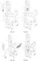
FIG. 1 and FIG. 2 each are a schematic view showing a partial structure of a microwave oven according to an embodiment of the present disclosure, in which a door body is in an open state; -
FIG. 3 is a schematic view showing a partial structure ofFIG. 1 , in which a cover body is not illustrated; -
FIG. 4 is a schematic enlarged view showing a partial structure ofFIG. 3 ; -
FIG. 5 is a left view ofFIG. 4 ; -
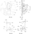
FIG. 6 andFIG. 7 each are a right view showing a partial structure of a microwave oven according to an embodiment of the present disclosure, in which a door body is in a closed state; -
FIG. 8 is a schematic view showing a partial structure ofFIG. 6 , in which a cover body is not illustrated; -
FIG. 9 is a schematic enlarged view showing a partial structure ofFIG. 8 ; -
FIG. 10 is a left view ofFIG. 9 ; -
FIG. 11 is a schematic view showing a structure of a cover body, a first microswitch, and a second microswitch according to an embodiment of the present disclosure; -
FIG. 12 and FIG. 13 each are a schematic view showing a structure of an interlock support and a second lever according to an embodiment of the present disclosure; -
FIG. 14 to FIG. 16 each are a schematic view showing a structure of a first lever according to an embodiment of the present disclosure; -
FIG. 17 and FIG. 18 each are a schematic view showing a structure of a second lever according to an embodiment of the present disclosure; -
FIG. 19 and FIG. 20 each are a right view showing a partial structure of a microwave oven according to an embodiment of the present disclosure, in which a door body is in a closed state; -
FIG. 21 is a schematic view showing a partial structure ofFIG. 19 , in which a cover body is not illustrated; -
FIG. 22 is a schematic enlarged view showing a structure of circled part A inFIG. 21 ; -
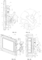
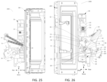
FIG. 23 to FIG. 25 each are a schematic view showing a partial structure of a microwave oven according to an embodiment of the present disclosure, in which a door body is in an open state; -
FIG. 26 is a schematic view showing a partial structure ofFIG. 24 , in which a cover body is not illustrated; -
FIG. 27 is a schematic enlarged view showing a structure of circled part B inFIG. 26 ; -
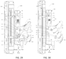
FIG. 28 is a right view of showing a partial structure of a microwave oven according to an embodiment of the present disclosure, in which a first door hook is just in contact with a first lever; -
FIG. 29 is a schematic view showing a partial structure ofFIG. 28 , in which a cover body is not illustrated; -
FIG. 30 is a right view of showing a partial structure of a microwave oven according to an embodiment of the present disclosure, in which a monitoring switch is triggered by a first drive portion; -
FIG. 31 is a right view of showing a partial structure of a microwave oven according to an embodiment of the present disclosure, in which a first door hook continues to move towards a door closing direction after a monitoring switch is triggered by a first drive portion; -
FIG. 32 is a right view showing a partial structure of a microwave oven according to an embodiment of the present disclosure, in which a first door hook just triggers a second lever; -
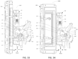
FIG. 33 is a right view showing a partial structure of a microwave oven according to an embodiment of the present disclosure, in which a first door hook moves towards a door opening direction; -
FIG. 34 is a right view showing a partial structure of a microwave oven according to an embodiment of the present disclosure, in which an interlock device is abnormally triggered; -
FIG. 35 and FIG. 36 each are a schematic view showing a structure of a support body and a second lever according to an embodiment of the present disclosure; -
FIG. 37 and FIG. 38 each are a schematic view showing a structure of a driver, an inclined block, and a support body according to an embodiment of the present disclosure; -
FIG. 39 and FIG. 40 each are a schematic view showing a structure of a first lever, a connector, a buffer member, and a support body according to an embodiment of the present disclosure; -
FIG. 41 and FIG. 42 each are a schematic view showing a structure of a door body, a first door hook, and a second door hook according to an embodiment of the present disclosure; -
FIG. 43 and FIG. 44 each are a schematic view showing a structure of a cover body according to an embodiment of the present disclosure; -
FIG. 45 and FIG. 46 each are a schematic view showing a structure of a support body according to an embodiment of the present disclosure; -
FIG. 47 is a sectional view taken along line C-C inFIG. 46 ; -
FIG. 48 is a left view ofFIG. 45 ; -
FIG. 49 and FIG. 50 each are a schematic view showing a structure of a drive link according to an embodiment of the present disclosure; -
FIG. 51 is a sectional view taken along line D-D inFIG. 50 ; -
FIG. 52 and FIG. 53 each are a schematic view showing a structure of a connector according to an embodiment of the present disclosure; -
FIG. 54 and FIG. 55 each are a schematic view showing a structure of a second lever according to an embodiment of the present disclosure; -
FIG. 56 is a schematic view showing a structure of an inclined block according to an embodiment of the present disclosure; -
FIG. 57 and FIG. 58 each are a schematic view showing a structure of a first door hook and a second door hook according to an embodiment of the present disclosure; -
FIG. 59 and FIG. 60 each are a schematic view showing a partial structure of a microwave oven according to an embodiment of the present disclosure; -
FIG. 61 is a schematic enlarged view of part III inFIG. 60 ; -
FIG. 62 to FIG. 68 each are a schematic view showing a partial structure of a microwave oven according to an embodiment of the present disclosure; and -
FIG. 69 and FIG. 70 each are a schematic view showing a direction of a force exerted on a drive lever according to an embodiment of the present disclosure. - Reference numerals of the accompanying drawings:
- 1000, microwave oven;
- 100, interlock device; 200, door body;
- 11, first door hook; 12, second door hook;
- 20, interlock support; 201, monitoring switch; 202, first microswitch; 203, second microswitch; 204, mounting space; 205, avoidance recess; 21, first limit portion; 22, support body; 221, third through hole; 222, first mounting post; 223, second mounting post; 23, cover body; 231, first through hole; 232, second through hole; 24, second limit portion; 25, first shield plate; 26, second shield plate; 27, third shield plate;
- 30, first lever; 31, first drive arm; 32, second drive arm; 33, first drive portion; 34, elastic member; 35, connection portion; 36, drive surface; 37, groove; 38, curved hook; 39, thinned region;
- 40, second lever; 41, first rotation arm; 42, second rotation arm; 43, third rotation arm; 44a, second drive portion; 44, second cooperation portion; 45, first cooperation portion; 46, third cooperation portion;
- 50, door closing buffer assembly; 51, buffer member; 52, connector; 521, avoidance notch; 53, driver; 54, inclined block;
- 124, accommodation groove; 21a, first switch; 22a, second switch; 23a, third switch; 24a, protection block; 30a, damping assembly; 301, first engagement region; 302, second engagement region; 31a, damper; 32a, drive lever; 321, accommodation groove; 322, rotation space; 323, swing space; 324, connection structure; 33a, swing block; 341, first elastic member; 342, second elastic member; 40a, inclined block; 50a, third elastic member.
- Embodiments of the present disclosure will be described in detail below with reference to examples thereof as illustrated in the accompanying drawings, throughout which same or similar elements, or elements having same or similar functions, are denoted by same or similar reference numerals. The embodiments described below with reference to the drawings are illustrative only, and are intended to explain, rather than limiting, the present disclosure.
- In the description of the present disclosure, it should be understood that the orientation or position relationship indicated by the terms such as "center", "longitudinal", "transverse", "length", "width", "thickness", "upper", "lower", "front", "rear", "left", "right", "vertical", "horizontal", "top", "bottom", "inner", "outer", "clockwise", "counterclockwise", "axial", "radial", and "circumferential" should be construed to refer to the orientation or the position as shown in the drawings, and is only for the convenience of describing the present disclosure and simplifying the description, rather than indicating or implying that the pointed apparatus or element must have a specific orientation, or be constructed and operated in a specific orientation, and therefore cannot be understood as a limitation of the present disclosure.
- In the description of the present disclosure, "first feature" and "second feature" may include one or more such features, and "plurality" means two or more. The first feature "on" or "under" the second feature may mean that the first feature is in direct contact with the second feature, or that the first feature and the second feature are in indirect contact through another feature between them. Moreover, the first feature "above" the second feature means that the first feature is directly above and obliquely above the second feature, or simply means that the level of the first feature is higher than that of the second feature.
- An
interlock device 100 of amicrowave oven 1000 according to one embodiment of the present disclosure and themicrowave oven 1000 having the same are described below with reference to the accompanying drawings. - As illustrated in
FIG. 1 to FIG. 10 , according to one embodiment of the present disclosure, themicrowave oven 1000 may include a machine body, adoor body 200, and theinterlock device 100 of themicrowave oven 1000 according to the embodiments of the present disclosure. Thedoor body 200 is mounted at the machine body. For example, thedoor body 200 is rotatably mounted at the machine body, to enable opening or closing of a holding cavity of the machine body, and to enable switching between an open state and a closed state of thedoor body 200. Theinterlock device 100 may implement corresponding functions based on a state switch of thedoor body 200. - The
interlock device 100 of themicrowave oven 1000 according to the embodiments of the present disclosure may include afirst door hook 11, aninterlock support 20, afirst lever 30, and asecond lever 40. - In an exemplary embodiment of the present disclosure, the
first door hook 11 may be mounted at thedoor body 200 to move relative to the machine body in response to a door opening or closing operation of thedoor body 200. Theinterlock support 20 is mounted at the machine body such that thefirst door hook 11 is capable of cooperating with theinterlock support 20 and members at theinterlock support 20 during a movement of thefirst door hook 11 relative to the machine body. - In an exemplary embodiment of the present disclosure, the
interlock support 20 is provided with three switches, namely amonitoring switch 201, afirst microswitch 202, and asecond microswitch 203. In another exemplary embodiment of the present disclosure, the monitoring switch may be a microswitch. When themonitoring switch 201, thefirst microswitch 202, and thesecond microswitch 203 are triggered sequentially, thedoor body 200 is determined to be closed, and thus themicrowave oven 1000 can be powered on and operate normally. - In the related art, a microwave oven adopts a microswitch layout for controlling a primary microswitch by an upper door hook of a movable door hook and indirectly controlling a secondary microswitch and a monitoring microswitch by a lower door hook during door closing. However, in the above-described manner of triggering the microswitches, a trigger sequence of the microswitches is prone to disorder during the door closing of the microwave oven, resulting in a potential safety hazard or affecting the service life of the microwave oven.
- In the embodiments of the present disclosure, as illustrated in
FIG. 1 to FIG. 10 , thefirst lever 30 is rotatably mounted at theinterlock support 20, and thesecond lever 40 is rotatably mounted at theinterlock support 20. Thefirst door hook 11 is configured to move relative to theinterlock support 20 and sequentially drive thefirst lever 30 and thesecond lever 40 to rotate during door closing of themicrowave oven 1000, to allow thesecond lever 40 to sequentially trigger thefirst microswitch 202 and thesecond microswitch 203 after themonitoring switch 201 is triggered by thefirst lever 30. - Therefore, the
monitoring switch 201, thefirst microswitch 202, and thesecond microswitch 203 are triggered sequentially through driving of a same door hook (i.e., through driving of the first door hook 11) and orderly transmission of two levers (i.e., thefirst lever 30 and the second lever 40), to avoid a problem of disorder of a trigger sequence of a plurality of switches. Therefore, both an open state and a closed state of adoor body 200 can be ensured to be detected accurately. In addition, damages to a circuit of themicrowave oven 1000 or even safety accidents can be avoided, which is conducive to improving the service life of themicrowave oven 1000. - For example, the
door body 200 is rotatably mounted at the machine body about a rotational axis extending in a vertical direction. During the door closing of themicrowave oven 1000, thedoor body 200 is rotated to allow thefirst door hook 11 to move rearwards relative to theinterlock support 20 substantially in a front-rear direction illustrated inFIG. 1 . In a movement process, thefirst door hook 11 is first brought into contact with thefirst lever 30 at theinterlock support 20 and drives thefirst lever 30 to rotate in a first direction (a counterclockwise direction illustrated inFIG. 1 ). When thefirst lever 30 rotates by a predetermined angle, thefirst lever 30 triggers themonitoring switch 201. Then, thefirst door hook 11 is in contact with thesecond lever 40 and drives thesecond lever 40 to rotate in a second direction (a clockwise direction illustrated inFIG. 1 ). When thesecond lever 40 rotates by a first predetermined angle, thefirst microswitch 202 is triggered. When thesecond lever 40 continues to rotate until a second predetermined angle is reached, thesecond microswitch 203 is triggered. Thus, themonitoring switch 201, thefirst microswitch 202, and thesecond microswitch 203 are sequentially and orderly triggered. - It should be noted that, in an entire rotation process of the
first lever 30 and thesecond lever 40, thefirst lever 30 and thesecond lever 40 may rotate completely under the driving of thefirst door hook 11, or thefirst lever 30 and thesecond lever 40 may be provided with an initial force by thefirst door hook 11 to start the rotation and then rotate under driving of other structures. All of these implementations are within the protection scope of the present disclosure. - In addition, in some embodiments, the
door body 200 of themicrowave oven 1000 may further include asecond door hook 12. For example, as illustrated inFIG. 1 to FIG. 10 , thefirst door hook 11 is a lower door hook, and thesecond door hook 12 is an upper door hook. The lower door hook is disposed below the upper door hook. In other embodiments of the present disclosure, thedoor body 200 may further include a third door hook, or more door hooks, or the like. The plurality of door hooks is in a vertical direction arranged at intervals. In an embodiment where a plurality of door hooks is provided, thefirst door hook 11 is configured to cooperate with two levers to indirectly trigger the three switches, ensuring that the three switches are switched on or off orderly. - The
first door hook 11 may be a fixed door hook, i.e., fixed with respect to thedoor body 200, to allow thefirst door hook 11 to be stable in position and structure in a process of driving thefirst lever 30 and thesecond lever 40 to rotate. In this way, orderly triggering for the microswitches can be prevented from being affected by a change in a position of thefirst door hook 11. Other door hooks such as thesecond door hook 12 and the third door hook may be fixed door hooks or movable door hooks. For example, the other door hooks may be rotatably or movably mounted at thedoor body 200. - According to the
interlock device 100 of themicrowave oven 1000 of the embodiment of the present disclosure, themonitoring switch 201, thefirst microswitch 202, and thesecond microswitch 203 are triggered sequentially through the driving of thefirst door hook 11 and orderly transmission of thefirst lever 30 and thesecond lever 40, to avoid the problem of disorder of the trigger sequence of the plurality of switches. Therefore, both the open state and the closed state of thedoor body 200 can be ensured to be detected accurately. In addition, damages to the circuit of themicrowave oven 1000 or even safety accidents can be avoided, which is conducive to improving the service life of themicrowave oven 1000. - Since the
interlock device 100 of themicrowave oven 1000 according to the embodiments of the present disclosure provides the above advantageous technical effects, themicrowave oven 1000 according to the embodiments of the present disclosure enables themonitoring switch 201, thefirst microswitch 202, and thesecond microswitch 203 to be triggered sequentially through the driving of thefirst door hook 11 and orderly transmission of thefirst lever 30 and thesecond lever 40, which avoids the problem of disorder of the trigger sequence of the plurality of switches. Therefore, both the open state and the closed state of thedoor body 200 can be ensured to be detected accurately. In addition, damages to the circuit of themicrowave oven 1000 or even safety accidents can be avoided, which is conducive to improving the service life of themicrowave oven 1000. - According to some embodiments of the present disclosure, as illustrated in
FIG. 1 to FIG. 10 , a rotational axis of thefirst lever 30 is located at a side of a rotation axis of thesecond lever 40 close to thefirst door hook 11. For example, as illustrated inFIG. 3 andFIG. 8 , the rotational axis of thefirst lever 30 is disposed at a front side of the rotational axis of thesecond lever 40, and thefirst door hook 11 is disposed at a front side of the rotational axis of thefirst lever 30. In this way, thefirst door hook 11 moves backwards during the door closing of themicrowave oven 1000. Therefore, thefirst door hook 11 can be in contact with thefirst lever 30, and then in contact with thesecond lever 40, which avoids a triggering disorder of the switches. - According to some embodiments of the present disclosure, as illustrated in
FIG. 1 to FIG. 10 , the rotational axis of thefirst lever 30 and the rotational axis of thesecond lever 40 are located at two sides of thefirst door hook 11 perpendicular to a door closing direction, respectively. For example, as illustrated inFIG. 3 andFIG. 8 , the rotational axis of thefirst lever 30 is located at an upper side of thefirst door hook 11, and the rotational axis of thesecond lever 40 is located at a lower side of thefirst door hook 11. The above arrangement can prevent an arrangement and rotations of thefirst lever 30 and thesecond lever 40 from interfering with each other. Further, the arrangement of thefirst lever 30 and thesecond lever 40 in the door closing direction (such as in the front-rear direction) is compact, and thus thefirst door hook 11 can be in contact with thefirst lever 30 and thesecond lever 40 for transmission without being too long. In this way, theinterlock device 100 has a compact structure. - A specific structure of the
first lever 30 according to some embodiments of the present disclosure is described below with reference to the accompanying drawings. - In some embodiments of the present disclosure, as illustrated in
FIG. 14 to FIG. 16 , thefirst lever 30 may include afirst drive arm 31 provided with afirst drive portion 33 configured to trigger themonitoring switch 201. As illustrated inFIG. 6 to FIG. 10 , thefirst door hook 11 is further configured to abut with thefirst drive arm 31 during the door closing of themicrowave oven 1000 to drive thefirst drive arm 31 to rotate around the rotational axis of thefirst lever 30 in the first direction. Therefore, thefirst drive portion 33 may be driven to rotate. In this way, thefirst drive portion 33 may rotate to a position triggering themonitoring switch 201 to switch on themonitoring switch 201. - It should be noted that a position of the
first drive portion 33 at thefirst drive arm 31 may be flexibly arranged based on actual conditions such as a spatial arrangement. For example, thefirst drive portion 33 may be provided at any position such as a middle or an end of thefirst drive arm 31 in a length direction of thefirst drive arm 31. - In some embodiments, the
first drive portion 33 may be a protrusion disposed at a side of thefirst drive arm 31 in an axial direction. In this way, thefirst drive portion 33 is free from interference of thefirst drive arm 31 during cooperation with themonitoring switch 201, which avoids a risk of bringing thefirst drive arm 31 into contact with themonitoring switch 201 by mistake. - In some embodiments of the present disclosure, as illustrated in
FIG. 14 to FIG. 16 , thefirst lever 30 may further include asecond drive arm 32 located at a side of thefirst drive arm 31 close to thefirst door hook 11. That is, thefirst drive arm 31 is located at a leading side of thesecond drive arm 32 in the first direction. - The
first door hook 11 is further configured to extend to a position between thefirst drive arm 31 and thesecond drive arm 32 during the door closing of themicrowave oven 1000, enabling thefirst door hook 11 to abut with thefirst drive arm 31 and drive thefirst lever 30 to start rotating in the first direction. Thefirst door hook 11 is further configured to abut with thesecond drive arm 32 during door opening of themicrowave oven 1000 to drive thefirst lever 30 to rotate in a second direction opposite to the first direction, enabling thefirst lever 30 to be separated from themonitoring switch 201. Therefore, themonitoring switch 201 can be switched off. - In this way, the
first door hook 11 is capable of driving thefirst lever 30 to rotate in two directions to trigger themonitoring switch 201 or restore a position of themonitoring switch 201, which is beneficial to simplifying the structure of theinterlock device 100. In other embodiments of the present disclosure, a structure for driving a position of thefirst lever 30 to be restored includes, but is not limited to, thesecond drive arm 32 cooperating with thefirst door hook 11. For example, in other embodiments, a restoring member such as a spring may be further provided to drive thefirst lever 30 to rotate in the second direction for restoring the position of thefirst lever 30 after thefirst door hook 11 moves in a door opening direction. - According to some embodiments of the present disclosure, as illustrated in
FIG. 1 to FIG. 10 , theinterlock device 100 may further include anelastic member 34 connected to theinterlock support 20 and thefirst lever 30. For example, theelastic member 34 may be a coil spring. One or a plurality of coil springs may be provided. In examples illustrated inFIG. 1 to FIG. 10 , twoelastic members 34 are provided and each are a tension spring. As illustrated inFIG. 15 and FIG. 16 , thefirst lever 30 is provided with aconnection portion 35. Theconnection portion 35 is a protrusion provided at a side surface of thefirst lever 30 facing away from thefirst drive portion 33. Each tension spring has an end connected to theinterlock support 20 and another end connected to theconnection portion 35. The two tension springs are spaced apart from each other at one end by a predetermined distance. - Further, the
elastic member 34 has a first drive state. Theelastic member 34 is configured to apply a drive force for rotating thefirst lever 30 in the first direction to thefirst lever 30 in the first drive state to allow thesecond drive arm 32 to drive thefirst door hook 11 to move in a door closing direction. - In an exemplary embodiment of the present disclosure, as illustrated in
FIG. 6 to FIG. 10 , thefirst door hook 11 is configured to move in the door closing direction to the position between thefirst drive arm 31 and thesecond drive arm 32 and abut withfirst drive arm 31 during the door closing of themicrowave oven 1000, to drive thefirst lever 30 to start rotating in the first direction. When thefirst lever 30 starts to rotate in the first direction or rotates by a small angle, theelastic member 34 is in the first drive state to automatically drive thefirst lever 30 to rotate in the first direction. In this way, thefirst door hook 11 is driven by thesecond drive arm 32 to continue to move in the door closing direction, in such a manner that an automatic door closing function is realized. In this case, even if a user cancels a force exerted on thedoor body 200 for closing thedoor body 200, thedoor body 200 can still be ensured to be closed properly, and thus thefirst door hook 11 can be ensured to move in the door closing direction until all three switches are triggered. On the one hand, the user can operate thedoor body 200 with less effort and more convenience. On the other hand, a problem of failing to close the door properly can be avoided. - In some embodiments, as illustrated in
FIG. 1 to FIG. 5 , theelastic member 34 has a second drive state. Theelastic member 34 is further configured to apply a drive force for rotating thefirst lever 30 in the second direction to thefirst lever 30 in the second drive state. Thefirst door hook 11 is further configured to abut with thefirst drive arm 31 during the door closing of themicrowave oven 1000 to switch theelastic member 34 from the second drive state into the first drive state. - In an exemplary embodiment of the present disclosure, in a door opened state, the
first lever 30 may be maintained at a desired position by theelastic member 34. On the one hand, thefirst lever 30 can be prevented from rotating in the first direction without being acted upon by thefirst door hook 11, avoiding mistakenly triggering themonitoring switch 201. On the other hand, thefirst door hook 11 can be ensured to move smoothly to the position between thefirst drive arm 31 and thesecond drive arm 32 during the door closing of themicrowave oven 1000 to prevent thefirst lever 30 from rotating and affecting cooperation between thefirst door hook 11 and thefirst lever 30. In addition, thefirst door hook 11 and thefirst drive arm 31 abut with each other to drive thefirst lever 30 to rotate in the first direction, which enables theelastic member 34 to switch the drive state in time along with the rotation of thefirst lever 30, and ensures that theelastic member 34 can drive the door to close in time. - In a door closed state, the
elastic member 34 is in the first drive state to allow thefirst lever 30 to abut with thefirst door hook 11 through thesecond drive arm 32, ensuring that thedoor body 200 remains in the closed state. When the door needs to be opened, thefirst door hook 11 is controlled by the user to move in the door opening direction and to abut with thesecond drive arm 32, enabling thefirst lever 30 to rotate in the second direction. When thefirst lever 30 rotates by a predetermined angle, theelastic member 34 is switched from the first drive state into the second drive state, which allows theelastic member 34 to drive thefirst lever 30 to rotate in the second direction to release a resistance on thefirst door hook 11 in time. Thus, thedoor body 200 can be opened easily. - In some embodiments of the present disclosure, as illustrated in
FIG. 9 andFIG. 14 toFIG. 16 , thesecond drive arm 32 may have a length smaller than a length of thefirst drive arm 31. Therefore, thefirst door hook 11 may be easily moved to the position between thefirst drive arm 31 and thesecond drive arm 32 during the door closing of themicrowave oven 1000, which prevents thesecond drive arm 32 from interfering with a movement of thefirst door hook 11. - In some embodiments of the present disclosure, as illustrated in
FIG. 9 andFIG. 14 toFIG. 16 , in an axial direction of thefirst lever 30, thesecond drive arm 32 has a thickness smaller than a thickness of thefirst drive arm 31. A thickness difference causes a gap between thesecond drive arm 32 and theinterlock support 20 to be greater than a gap between thefirst drive arm 31 and theinterlock support 20. During the door closing of themicrowave oven 1000, even if thesecond drive arm 32 interferes with the movement of thefirst door hook 11 in the door closing direction, thesecond drive arm 32 or thefirst door hook 11 is likely to be deformed to move thefirst door hook 11 to the position between thefirst drive arm 31 and thesecond drive arm 32. Thefirst door hook 11 and thefirst drive arm 31 are less likely to be deformed, which causes thefirst door hook 11 to move to a side of thefirst drive arm 31 away from thesecond drive arm 32, ensuring stability of the cooperation between thefirst door hook 11 and thefirst lever 30. - In some specific embodiments, as illustrated in
FIG. 15 and FIG. 16 , in the axial direction of thefirst lever 30, thesecond drive arm 32 has a thinnedregion 39 located at a surface of thesecond drive arm 32. Therefore, when thefirst lever 30 is mounted at theinterlock support 20, a predetermined gap can be formed between the thinnedregion 39 of thesecond drive arm 32 and theinterlock support 20. When thefirst lever 30 is rotated in the first direction to a position triggering themonitoring switch 201 due to being triggered by mistake, thefirst door hook 11 may forcibly pass through the gap and move to the position between thefirst drive arm 31 and thesecond drive arm 32 through closing the door. Then through opening the door, thefirst door hook 11 may drive thefirst lever 30 to rotate in the second direction for restoring the position of thefirst lever 30. - For example, as illustrated in
FIG. 15 and FIG. 16 , theinterlock support 20 includes asupport body 22 and acover body 23. Thefirst lever 30 is mounted between thesupport body 22 and thecover body 23. The thinnedregion 39 may be a notch groove formed at a side of thesecond drive arm 32 facing towards thesupport body 22, which enables the gap to be formed between thesecond drive arm 32 and thesupport body 22. - In addition, the
first door hook 11 may have a thickness gradually decreasing in the door closing direction. Thus, a rear end of thefirst door hook 11 has a smaller thickness, while a front end of thefirst door hook 11 has a greater thickness, as illustrated inFIG. 1 . When thefirst lever 30 triggers themonitoring switch 201 by mistake, the structure of thick front end and thin rear end of thefirst door hook 11 enables thefirst door hook 11 to be moved from the thinnedregion 39 to the position between thefirst drive arm 31 and thesecond drive arm 32 easily. Therefore, an abnormal triggering problem can be solved easily. - According to some embodiments of the present disclosure, as illustrated in
FIG. 3 andFIG. 8 , theinterlock support 20 may be provided with afirst limit portion 21. Thefirst limit portion 21 is configured to abut with thefirst lever 30 in a door closed state to block thefirst lever 30 from rotating in the first direction. In other words, thefirst limit portion 21 may limit a limit position thefirst lever 30 is rotated to in the first direction, to avoid damages to themonitoring switch 201 or thefirst door hook 11 caused by an excessive rotation angle of thefirst lever 30. - For example, in an embodiment where the
elastic member 34 is provided, theelastic member 34 drives thefirst lever 30 to rotate in the first direction to drive thefirst door hook 11 to move in the door closing direction, realizing automatic door closing. When thefirst lever 30 abuts with thefirst limit portion 21, a limitation of thefirst limit portion 21 realizes a force balance of thefirst lever 30, and thus thefirst lever 30 is kept from rotating under driving of theelastic member 34. Thefirst lever 30 can be maintained at a position that provides a stable engagement with thefirst door hook 11 and keeps thedoor body 200 closed. - According to some embodiments of the present disclosure, as illustrated in
FIG. 3 andFIG. 8 , theinterlock device 100 may further include a door closingbuffer assembly 50 connected to theinterlock support 20 and thefirst lever 30. For example, the door closingbuffer assembly 50 is connected to thefirst drive arm 31 of thefirst lever 30. - The door closing
buffer assembly 50 is configured to apply a buffer force to thefirst lever 30 in a direction opposite to the first direction during the door closing of themicrowave oven 1000. Therefore, a buffer action for the door closing of themicrowave oven 1000 can be realized, which avoids a violent collision between thedoor body 200 and the machine body during the door closing of themicrowave oven 1000, and also facilitates a noise reduction during the door closing of themicrowave oven 1000. - A specific structure of the door closing
buffer assembly 50 is not specifically limited in the present disclosure, as long as the structure can provide the buffer action for the door closing of themicrowave oven 1000. For example, the door closingbuffer assembly 50 may include a damper, a spring, a compression spring, or the like. - For example, in some embodiments, as illustrated in
FIG. 3, FIG. 4 ,FIG. 8 , andFIG. 9 , the door closingbuffer assembly 50 includes abuffer member 51 and aconnector 52. Thebuffer member 51 has an end rotatably connected to theinterlock support 20. Theconnector 52 is rotatably connected to another end of thebuffer member 51 and thefirst drive arm 31, respectively. In this way, during the rotation of thefirst lever 30, thebuffer member 51 serves as a buffer, while such a rotatable connection structure is adapted to the rotation of thefirst lever 30 to avoid jamming. - In addition, as illustrated in
FIG. 3, FIG. 4 ,FIG. 8 , andFIG. 9 , thefirst drive arm 31 has adrive surface 36. Theconnector 52 is rotatably mounted at thefirst drive arm 31. Further, as illustrated inFIG. 4 , theconnector 52 forms a predetermined angle with thedrive surface 36 in a door opened state. Another end of thebuffer member 51 is rotatably connected to theconnector 52. Thedrive surface 36 is capable of abutting with theconnector 52 after thefirst lever 30 rotates in the first direction by the predetermined angle during the door closing of themicrowave oven 1000, to drive theconnector 52 to rotate. - Since the
connector 52 is arranged at the predetermined angle to thedrive surface 36 in the door opened state, when thefirst door hook 11 is just in contact with thefirst lever 30 and drives thefirst lever 30 to rotate in the first direction, thebuffer member 51 is kept from applying a buffer force to thefirst lever 30, which enables thefirst door hook 11 to easily drive thefirst lever 30 to rotate. - In some specific embodiments, as illustrated in
FIG. 3, FIG. 4 ,FIG. 8 , andFIG. 9 , a side of thefirst drive arm 31 facing towards the door closingbuffer assembly 50 has agroove 37. A bottom wall surface of thegroove 37 is formed as thedrive surface 36. One side surface of thegroove 37 is connected to a hole shaft of theconnector 52, while another side surface of thegroove 37 is provided with acurved hook 38 spaced apart from thedrive surface 36 by a predetermined distance. Thebuffer member 51 is a damper. The damper is connected to the hole shaft of theconnector 52 through an opening of thegroove 37. Theinterlock device 100 further includes theelastic member 34 connected to thefirst lever 30. - The
elastic member 34 is configured to apply a drive force for rotating thefirst lever 30 in the second direction in the door opened state, which enables thefirst door hook 11 to be smoothly moved until abutting with thefirst drive arm 31. In this case, theconnector 52 and thedrive surface 36 form the predetermined angle to keep the damper from generating a buffer force. Thefirst door hook 11 is in contact with thefirst drive arm 31 and is configured to drive thefirst lever 30 to rotate in the first direction during the door closing of themicrowave oven 1000. Since the damper provides no buffer force, thefirst door hook 11 only needs to drive thefirst lever 30 against the drive force of theelastic member 34, and thus a small resistance is generated. When thefirst lever 30 rotates until theconnector 52 abuts with thedrive surface 36, a state of theelastic member 34 is switched into applying the drive force for rotating thefirst lever 30 in the first direction to actively drive thefirst lever 30 to rotate, thefirst door hook 11 to move, and thedoor body 200 to close. In this case, the damper generates a buffer force to reduce noises generated during the door closing of themicrowave oven 1000. Thefirst door hook 11 is configured to pull thefirst lever 30 to rotate in the second direction and theconnector 52 is configured to rotate relative to thefirst drive arm 31 during the door opening of themicrowave oven 1000. In this way, a predetermined angle is formed between theconnector 52 and thedrive surface 36, and the curved hook abuts with theconnector 52 to prevent the angle from being too large and prevent theconnector 52 from falling out of thegroove 37, which ensure theconnector 52 to be stably connected to thefirst lever 30. - For example, in other embodiments, the door closing
buffer assembly 50 may include thebuffer member 51. Thebuffer member 51 is an elastic sheet or a compression spring. The door closingbuffer assembly 50 is formed as a buffer energy accumulation assembly. In an exemplary embodiment of the present disclosure, one end of the elastic sheet is connected to theinterlock support 20, and thefirst lever 30 abuts with another end of the elastic sheet. The elastic sheet can be elastically deformed to accumulate energy. - The
first lever 30 is configured to rotate in the first direction and compress the other end of the elastic sheet during the door closing of themicrowave oven 1000, to increase a bending degree of the elastic sheet and accumulate energy, which achieves the buffer action and energy accumulation. During the door opening of themicrowave oven 1000, the elastic sheet can release the accumulated energy to apply the drive force for rotating thefirst lever 30 in the second direction. Therefore, thefirst lever 30 can push thefirst door hook 11 and thedoor body 200 to move towards the door opening direction, which is conducive to the door opening of themicrowave oven 1000. In the door closed state, a direction of the drive force exerted by the elastic sheet on thefirst lever 30 is directed towards a rotation center of thefirst lever 30 or near the rotation center of thefirst lever 30. In this case, no component force or only a small component force is provided by the elastic sheet in a rotation direction of thefirst lever 30, which ensures thedoor body 200 to be tightly closed. - The
second lever 40 according to some embodiments of the present disclosure is described below in conjunction with the accompanying drawings. - In some embodiments of the present disclosure, as illustrated in
FIG. 17 and FIG. 18 , thesecond lever 40 includes afirst rotation arm 41, asecond rotation arm 42, and athird rotation arm 43. Thefirst rotation arm 41, thesecond rotation arm 42, and thethird rotation arm 43 are sequentially arranged in the second direction (a clockwise direction illustrated inFIG. 3 ). As illustrated inFIG. 1 to FIG. 10 , thefirst door hook 11 is capable of abutting with thefirst rotation arm 41 during the door closing of themicrowave oven 1000 to drive thesecond lever 40 to rotate in the second direction. Therefore, thesecond rotation arm 42 and thethird rotation arm 43 are driven to rotate in the second direction. Thesecond rotation arm 42 is capable of triggering thefirst microswitch 202. Thethird rotation arm 43 is capable of triggering thesecond microswitch 203. Therefore, two microswitches can be driven to be switched on sequentially by one lever. - In some embodiments, as illustrated in
FIG. 17 and FIG. 18 , at least two of thefirst rotation arm 41, thesecond rotation arm 42, and thethird rotation arm 43 are offset from each other in an axial direction of thesecond lever 40. Therefore, an angle formed by thefirst rotation arm 41, thesecond rotation arm 42, and thethird rotation arm 43 in the second direction is small, and position interference is less likely to occur, which is beneficial to make the structure of theinterlock device 100 more compact in a movement direction of thefirst door hook 11. - For example, as illustrated in
FIG. 17 and FIG. 18 , in the axial direction of thesecond lever 40, thefirst rotation arm 41 and thethird rotation arm 43 are located at a same position, while thesecond rotation arm 42 is offset from thefirst rotation arm 41 and thethird rotation arm 43. In this way, the three rotation arms are distributed in two layers in the axial direction. Correspondingly, thefirst microswitch 202 and thesecond microswitch 203 can be arranged in two layers in the axial direction of thesecond lever 40. Thefirst door hook 11 is capable of driving thesecond lever 40 from a side of thefirst rotation arm 41 facing away from thethird rotation arm 43. Therefore, interference between thefirst door hook 11, thefirst microswitch 202, and thesecond microswitch 203 can be avoided. - In some embodiments, the
second rotation arm 42 may be provided with asecond drive portion 44a, which enables thesecond rotation arm 42 and thefirst microswitch 202 to be at least partially offset from each other in the axial direction to meet spatial arrangement requirements. - According to some embodiments of the present disclosure, as illustrated in
FIG. 11 to FIG. 13 , theinterlock support 20 may include asupport body 22 and acover body 23. Thecover body 23 covers thesupport body 22 to allow thecover body 23 to cooperate with thesupport body 22 to define a mountingspace 204. Thefirst lever 30 and thesecond lever 40 are mounted in the mountingspace 204, for limiting positions of thefirst lever 30 and thesecond lever 40, which ensures that the two levers can rotate stably and are less likely to be interfered with or touched by other structures to prevent a normal operation from being affected. - As illustrated in
FIG. 6 to FIG. 10 , thefirst door hook 11 is capable of extending into the mountingspace 204 during the door closing of themicrowave oven 1000 to be in contact with thefirst lever 30 and thesecond lever 40. The mountingspace 204 is further capable of shielding and protecting a cooperation structure between thefirst door hook 11 and the lever to ensure smooth driving. Furthermore, the mountingspace 204 is further capable of guiding thefirst door hook 11, which ensures that thefirst door hook 11 can be accurately in contact with thefirst lever 30 and thesecond lever 40. - In some embodiments, as illustrated in
FIG. 12 and FIG. 13 , thesupport body 22 may be provided with a first mountingpost 222 and a second mountingpost 223. Thefirst lever 30 is arranged around the first mountingpost 222. Thesecond lever 40 is arranged around the second mountingpost 223. In addition, each of the first mountingpost 222 and the second mountingpost 223 has an end inserted into thecover body 23 to limit positions of thesupport body 22 and thecover body 23 through cooperation with thecover body 23, which prevents thecover body 23 and thesupport body 22 from being misaligned or deformed to avoid an influence on triggering for the switch. - In addition, in some embodiments, as illustrated in
FIG. 1 to FIG. 5 andFIG. 11 to FIG. 13 , themonitoring switch 201 is arranged at a side of thecover body 23 facing away from thesupport body 22. Thecover body 23 has a first throughhole 231. Thefirst lever 30 is provided with afirst drive portion 33. Thefirst drive portion 33 is capable of passing through the first throughhole 231 to extend to the side of thecover body 23 facing away from thesupport body 22. During the rotation of thefirst lever 30, thefirst drive portion 33 rotates in the first throughhole 231 with thefirst lever 30 to facilitate triggering for themonitoring switch 201. Themonitoring switch 201 may be disposed outside the mountingspace 204 to avoid position interference with members in the mountingspace 204, such as avoiding interference with the door closingbuffer assembly 50, which enables the position arrangement to be reasonable. - As illustrated in
FIG. 1 to FIG. 5 andFIG. 11 to FIG. 13 , thefirst microswitch 202 is disposed at the side of thecover body 23 facing away from thesupport body 22, and thesecond microswitch 203 is arranged at the mountingspace 204. Thecover body 23 may further have a second throughhole 232. Thesecond lever 40 is provided with asecond drive portion 44a. Thesecond drive portion 44a is capable of passing through the second throughhole 232 to extend to the side of thecover body 23 facing away from thesupport body 22. During the rotation of thesecond lever 40, thesecond drive portion 44a rotates in the second throughhole 232 with thesecond lever 40 to facilitate triggering for thefirst microswitch 202 located outside the mountingspace 204. A part of thesecond lever 40 located within mountingspace 204 is capable of triggering thesecond microswitch 203 located within mountingspace 204. Thefirst microswitch 202 and thesecond microswitch 203 are located at different sides of thecover body 23, which prevents thefirst microswitch 202 and thesecond microswitch 203 from interfering with each other. For example, in the axial direction of thesecond lever 40, a projection of thefirst microswitch 202 may at least partially coincide with a projection of thesecond microswitch 203. In this way, an arrangement of the two microswitches can be more compact, and thus thefirst microswitch 202 and thesecond microswitch 203 can be sequentially triggered by thesecond lever 40 faster. - The
microwave oven 1000 according to a specific embodiment of the present disclosure is described in detail below with reference to the accompanying drawings. It should be understood that the following description is illustrative only and should not be construed as a limitation of the present disclosure. - As illustrated in
FIG. 1 to FIG. 18 , themicrowave oven 1000 according to the embodiment of the present disclosure includes thedoor body 200, the machine body, and theinterlock device 100. Theinterlock device 100 includes thefirst door hook 11, thesecond door hook 12, theinterlock support 20, thefirst lever 30, thesecond lever 40, themonitoring switch 201, thefirst microswitch 202, thesecond microswitch 203, theelastic member 34, the door closingbuffer assembly 50, adriver 53, and aninclined block 54. - The
door body 200 is rotatably mounted at the machine body around a vertical axis. Thefirst door hook 11 and thesecond door hook 12 are fixedly mounted at thedoor body 200. Further, thesecond door hook 12 is located above thefirst door hook 11. Theinterlock support 20 is mounted at the machine body and includes thesupport body 22 and thecover body 23 to define the mountingspace 204. Thefirst lever 30 and thesecond lever 40 are rotatably mounted in the mountingspace 204. Thefirst lever 30 includes thefirst drive arm 31, thesecond drive arm 32, and thefirst drive portion 33. Thefirst drive portion 33 passes through the first throughhole 231 of thecover body 23. Thesecond lever 40 includes thefirst rotation arm 41, thesecond rotation arm 42, thethird rotation arm 43, and thesecond drive portion 44a passing through the second throughhole 232 of thecover body 23. Thesecond microswitch 203 is arranged in the mountingspace 204. Themonitoring switch 201 and thefirst microswitch 202 are arranged at the side of thecover body 23 facing away from thesupport body 22. Thesupport body 22 has a third throughhole 221. Theelastic member 34 is arranged at a side of thesupport body 22 facing away from thecover body 23. Theconnection portion 35 of thefirst lever 30 passes through the third throughhole 221 to be connected to theelastic member 34. - In addition, the
inclined block 54 is movably mounted at thesupport body 22 in a vertical direction. Two ends of thedriver 53 abut with theinclined block 54 and thesupport body 22, respectively, to apply an upward driving force to theinclined block 54. - As illustrated in
FIG. 1 to FIG. 5 , thefirst door hook 11 and thesecond door hook 12 are separated from the machine body in the door opened state. Thedriver 53 drives theinclined block 54 to a high position. Thefirst lever 30 rotates in the clockwise direction to a limit position against an edge of thesupport body 22 under a pulling force of theelastic member 34 and is separated from themonitoring switch 20. Thesecond lever 40 is at a position separated from thefirst microswitch 202 and thesecond microswitch 203. - During the door closing of the
microwave oven 1000, thedoor body 200 is pushed to allow thefirst door hook 11 and thesecond door hook 12 to move in the door closing direction, i.e., to move backwards. The rear end of thefirst door hook 11 extends to the position between thefirst drive arm 31 and thesecond drive arm 32 and is configured to abut with thefirst drive arm 31 to push thefirst lever 30 to rotate in the counterclockwise direction. When thefirst lever 30 rotates by the predetermined angle, the pulling force of theelastic member 34 is switched to drive thefirst lever 30 to rotate in the counterclockwise direction, which allows thesecond drive arm 32 of thefirst lever 30 to automatically pull thefirst door hook 11 to move backwards. Further, theconnector 52 is in contact with thedrive surface 36. Thedrive surface 36 is configured to drive theconnector 52 to move. Thebuffer member 51 provides the buffer action. Thefirst lever 30 rotates to enable thefirst drive portion 33 to trigger themonitoring switch 201. Then, when moved until being brought into contact with thesecond lever 40, thefirst door hook 11 drives thesecond lever 40 to rotate in the clockwise direction. Thefirst microswitch 202 and thesecond microswitch 203 are sequentially triggered by thesecond drive portion 44a and thethird rotation arm 43 of thesecond lever 40. Thesecond door hook 12 is configured to abut with theinclined block 54 during the door closing of themicrowave oven 1000. Theinclined block 54 is configured to compress thedriver 53 to move a hook portion of thesecond door hook 12 to a rear side of theinclined block 54. In this way, a position of thesecond door hook 12 is limited by theinclined block 54 to keep thedoor body 200 closed. - As illustrated in
FIG. 6 to FIG. 10 , thefirst lever 30 is configured to stop rotating when rotated until abutting with thefirst limit portion 21, and thesecond lever 40 is configured to stop rotating after triggering thesecond microswitch 203. In this case, under the pulling force of theelastic member 34, thefirst door hook 11 is blocked by thesecond drive arm 32 of thefirst lever 30. Therefore, thedoor body 200 is kept in the door closed state, and thefirst lever 30 and thesecond lever 40 are kept in positions where themonitoring switch 201, thefirst microswitch 202, and thesecond microswitch 203 are enabled to be switched on. - The
door body 200 is configured to rotate in reverse to be opened during the door opening of themicrowave oven 1000 to allow thefirst door hook 11 to move forwards. In the movement process, a block force against thesecond lever 40 is first canceled. Thesecond lever 40 is configured to rotate in the counterclockwise direction under a rebound force of thefirst microswitch 202 and a rebound force of thesecond microswitch 203 to cancel triggering for thefirst microswitch 202 and thesecond microswitch 203. Further, thefirst door hook 11 is configured to abut with thesecond drive arm 32 during the movement of thefirst door hook 11 to drive thefirst lever 30 against an elastic force of theelastic member 34 and to rotate in the clockwise direction. In this way, triggering for themonitoring switch 201 is released by thefirst drive portion 33. When the pulling force of theelastic member 34 is switched to drive thefirst lever 30 to rotate in the clockwise direction, thefirst lever 30 is automatically restored to the position against the edge of thesupport body 22 under the driving of theelastic member 34 and stays at the position. In addition, thefirst lever 30 is capable of driving thefirst door hook 11 to move forwards, which allows thedoor body 200 to be sprang open. Thesecond door hook 12 is configured to abut with theinclined block 54 again during the door opening of themicrowave oven 1000. Theinclined block 54 is configured to compress thedriver 53 to move the hook portion of thesecond door hook 12 to a front side of theinclined block 54, in such a manner that the limit exerted by theinclined block 54 on thesecond door hook 12 can be released for opening thedoor body 200. - In summary, the
first door hook 11 cooperates with the two levers to trigger the three switches, respectively. The switches are in indirect contact with thefirst door hook 11. Further, themonitoring switch 201, thefirst microswitch 202, and thesecond microswitch 203 can be triggered sequentially, which ensures safety of the machine. - The
interlock device 100 of themicrowave oven 1000 according to one embodiment of the present disclosure and themicrowave oven 1000 having theinterlock device 100 are described below with reference to the accompanying drawings. - As illustrated in
FIG. 19 to FIG. 58 , themicrowave oven 1000 according to the embodiment of the present disclosure may include a machine body, adoor body 200, and theinterlock device 100 of themicrowave oven 1000 according to the embodiments of the present disclosure. Thedoor body 200 is mounted at the machine body. For example, thedoor body 200 is rotatably mounted at the machine body to open or close a holding cavity of the machine body and switch between an open state and a closed state of thedoor body 200. Theinterlock device 100 can implement corresponding functions based on a state switch of thedoor body 200. - The
interlock device 100 of themicrowave oven 1000 according to the embodiments of the present disclosure may include thefirst door hook 11, theinterlock support 20, and thesecond lever 40. - In an exemplary embodiment of the present disclosure, as illustrated in
FIG. 21 ,FIG. 41 ,FIG. 42 ,FIG. 57, and FIG. 58 , thefirst door hook 11 may be mounted at thedoor body 200 to move relative to the machine body in response to a door opening or closing operation of thedoor body 200. Theinterlock support 20 is mounted at the machine body such that thefirst door hook 11 is capable of cooperating with theinterlock support 20 and members at theinterlock support 20 during a movement of thefirst door hook 11 relative to the machine body. - In an exemplary embodiment of the present disclosure, the
interlock support 20 is provided with two switches, namely thefirst microswitch 202 and thesecond microswitch 203. Thefirst microswitch 202 and thesecond microswitch 203 need to be triggered sequentially to ensure that themicrowave oven 1000 can be powered on and operated normally. - In the related art, a split door hook is adopted for a design of slow door closing /soft door closing of a side pull microwave oven. A slow door closing process is realized by utilizing a buckle, a slideway, a spring, a damper, or the like. However, such a slow door closing system occupies a large space. To ensure that a sufficient space is reserved for other members, schemes with different size proportions need to be designed for models having different volumes, which has poor universality and produces high costs.
- In the embodiments of the present disclosure, as illustrated in
FIG. 21 ,FIG. 25 , andFIG. 36 , thesecond lever 40 is rotatably mounted at theinterlock support 20. Thesecond lever 40 may include thefirst rotation arm 41 provided with afirst cooperation portion 45, thesecond rotation arm 42 provided with asecond cooperation portion 44, and thethird rotation arm 43 provided with athird cooperation portion 46. In addition, thefirst cooperation portion 45, thesecond cooperation portion 44, and thethird cooperation portion 46 are sequentially arranged about the rotational axis of thesecond lever 40 in the first direction (a clockwise direction illustrated inFIG. 21 ). On the one hand, sequential triggering for the microswitches at theinterlock support 20 can be facilitated to avoid the disorder of the trigger sequence. On the other hand, a reasonable arrangement of the microswitches at theinterlock support 20 can be facilitated to realize a compact structure of the machine body of themicrowave oven 1000. - During the door closing of the
microwave oven 1000, as illustrated inFIG. 19 to FIG. 21 , thefirst door hook 11 is configured to move in the door closing direction to abut with thefirst cooperation portion 45 and drive thesecond lever 40 to rotate in the first direction, which allows thethird cooperation portion 46 to trigger thesecond microswitch 203 after thefirst microswitch 202 is triggered by thesecond cooperation portion 44. Thefirst microswitch 202 and thesecond microswitch 203 can be sequentially triggered for detecting the open state or the closed state of thedoor body 200, which ensures thatmicrowave oven 1000 can operate normally and avoids the disorder of the trigger sequence. Therefore, a potential safety hazards of themicrowave oven 1000 due to the disorder of the trigger sequence of the microswitches is avoided. - It should be noted that each of the
first microswitch 202 and thesecond microswitch 203 may be provided with an elastic sheet. Thesecond cooperation portion 44 and thethird cooperation portion 46 are configured to trigger thefirst microswitch 202 and thesecond microswitch 203 through the elastic sheets. To ensure the trigger sequence, the microswitches at theinterlock support 20 should be arranged reasonably. An angle formed between the elastic sheet of thefirst microswitch 202 and thesecond cooperation portion 44 about the rotational axis should be smaller than an angle formed between the elastic sheet of thesecond microswitch 203 and thethird cooperation portion 46 about the rotational axis. - For example, as illustrated in
FIG. 19 to FIG. 22 , thedoor body 200 is rotatably mounted at the machine body about a rotational axis extending in a vertical direction. During the door closing of themicrowave oven 1000, thedoor body 200 is rotated to allow thefirst door hook 11 to move rearwards relative to theinterlock support 20 substantially in a front-rear direction illustrated inFIG. 17 . In a movement process, thefirst door hook 11 is first brought into contact with thefirst cooperation portion 45 and drives thesecond lever 40 to rotate in the first direction (a clockwise direction illustrated inFIG. 17 ). Thesecond cooperation portion 44 and thethird cooperation portion 46 rotate by the same angle in the first direction after thesecond lever 40 starts to rotate. With a reasonable arrangement of thefirst microswitch 202 and thesecond microswitch 203 at theinterlock support 20, thesecond cooperation portion 44 may be in contact with thefirst microswitch 202 to trigger thefirst microswitch 202 when thesecond lever 40 rotates to the first predetermined angle. When thesecond lever 40 continues to rotate until the second predetermined angle is reached, thethird cooperation portion 46 is in contact with thesecond microswitch 203 to trigger thesecond microswitch 203. Thus, thefirst microswitch 202 and thesecond microswitch 203 are orderly triggered. - Compared with the related art, in the present disclosure, the
first cooperation portion 45, thesecond cooperation portion 44, and thethird cooperation portion 46 are sequentially arranged in the first direction. That is, projections of thefirst cooperation portion 45, thesecond cooperation portion 44, and thethird cooperation portion 46 in a cross-section perpendicular to an axis of thesecond lever 40 are offset from each other sequentially. In this way, the sequential triggering for thefirst microswitch 202 and thesecond microswitch 203 can be realized without increasing an arm length of each of thefirst rotation arm 41, thesecond rotation arm 42, and thesecond rotation arm 42. As a result, an occupied space is reduced, and the structure of theinterlock device 100 is more compact while ensuring the sequential triggering for the microswitches. In addition, theinterlock device 100 can be mounted in amicrowave oven 1000 having a small volume, which provides good versatility and can effectively reduce manufacturing costs. - According to the
interlock device 100 of themicrowave oven 1000 of the embodiment of the present disclosure, thefirst cooperation portion 45, thesecond cooperation portion 44, and thethird cooperation portion 46 are sequentially arranged about the rotational axis of thesecond lever 40 in the first direction. Thesecond cooperation portion 44 and thethird cooperation portion 46 are capable of sequentially triggering corresponding microswitches after thefirst cooperation portion 45 is driven by thefirst door hook 11, which ensures orderliness of triggering the microswitches, avoiding the problem of disorder of the trigger sequence. Therefore, an effective detection of the open state or the closed state of themicrowave oven 1000 can be realized. In addition, the arm length of the rotation arm can be effectively reduced while ensuring the trigger sequence, in such a manner that a small space is occupied, which realizes a compact structure of theinterlock device 100. Therefore, theinterlock device 100 of the present disclosure can be applied to themicrowave oven 1000 having a small volume and has strong versatility, which can effectively reduce manufacturing costs. - In addition, in some embodiments, the
door body 200 of themicrowave oven 1000 may further include thesecond door hook 12. For example, as illustrated inFIG. 19 to FIG. 34 , thefirst door hook 11 is a lower door hook, and thesecond door hook 12 is an upper door hook. The lower door hook is disposed below the upper door hook. In other embodiments of the present disclosure, thedoor body 200 may further include a third door hook, or more door hooks, or the like. The plurality of door hooks is in a vertical direction arranged at intervals. In an embodiment where a plurality of door hooks is provided, thefirst door hook 11 is configured to cooperate with thesecond lever 40 to indirectly trigger the two switches, ensuring that the two switches are switched on or off orderly. - The
first door hook 11 may be a fixed door hook, i.e., fixed with respect to thedoor body 200, to allow thefirst door hook 11 to be stable in position and structure in a process of driving thesecond lever 40 to rotate. In this way, the orderly triggering for the microswitches can be prevented from being affected by a change in the position of thefirst door hook 11. Other door hooks such as thesecond door hook 12 and the third door hook may be fixed door hooks or movable door hooks. For example, the other door hooks may be rotatably or movably mounted at thedoor body 200. - The
interlock device 100 of themicrowave oven 1000 according to the embodiments of the present disclosure provides the above advantageous effects. Therefore, for themicrowave oven 1000 according to the embodiment of the present disclosure, thefirst cooperation portion 45, thesecond cooperation portion 44, and thethird cooperation portion 46 are sequentially arranged about the rotational axis of thesecond lever 40 in the first direction. Thesecond cooperation portion 44 and thethird cooperation portion 46 are capable of sequentially triggering corresponding microswitches after thefirst cooperation portion 45 is driven by thefirst door hook 11, which ensures orderliness of triggering the microswitches, avoiding the problem of disorder of the trigger sequence. Therefore, an effective detection of the open state or the closed state of themicrowave oven 1000 can be realized. In addition, the arm length of the rotation arm can be effectively reduced while ensuring the trigger sequence, in such a manner that a small space is occupied, which realizes a compact structure of theinterlock device 100. Therefore, theinterlock device 100 of the present disclosure can be applied to themicrowave oven 1000 having a small volume and has strong versatility, which can effectively reduce the manufacturing costs. - According to some embodiments of the present disclosure, as illustrated in
FIG. 54 and FIG. 55 , an angle formed between thefirst cooperation portion 45 and thesecond cooperation portion 44 with respect to an axis of thesecond lever 40 may be denoted by a, while an angle formed between thesecond cooperation portion 44 and thethird cooperation portion 46 with respect to the axis of thesecond lever 40 may be denoted by 0, where α<β. On the one hand, the orderly triggering for the microswitches can be more satisfactory. On the other hand, a space of theinterlock device 100 occupied by thesecond lever 40 can be reduced through decreasing the angle formed between thefirst cooperation portion 45 and thesecond cooperation portion 44. - In an exemplary embodiment of the present disclosure, with the angle α formed between the
first cooperation portion 45 and thesecond cooperation portion 44 about the rotational axis and the angle β formed between thesecond cooperation portion 44 and thethird cooperation portion 46 about the rotational axis, an effect of orderly triggering can be realized in cooperation with the microswitches at theinterlock support 20, which avoids the potential safety hazard of themicrowave oven 1000 due to the disorder of the trigger sequence. After thefirst microswitch 202 is triggered by thesecond cooperation portion 44, thesecond lever 40 needs to continue rotating by the second predetermined angle to allow thethird cooperation portion 46 to trigger thesecond microswitch 203. By allowing the angle β to be greater than the angle α, a distance between thesecond cooperation portion 44 and thethird cooperation portion 46 at a plane perpendicular to the rotational axis can be increased. Therefore, satisfaction with the effect of the orderly triggering for the microswitches grows as the second predetermined angle increases. - With α<β, the angle between the
first cooperation portion 45 and thesecond cooperation portion 44 with respect to the axis of thesecond lever 40 can be reasonably reduced when the angle between thesecond cooperation portion 44 and thethird cooperation portion 46 with respect to the axis of thesecond lever 40 is constant. In this way, space resources of theinterlock device 100 occupied by thesecond lever 40 can be reduced while ensuring the orderly triggering for the microswitches. Therefore, the position interference with other members in theinterlock device 100 can be avoided, which is beneficial to realizing the compact structure of theinterlock device 100. - As illustrated in
FIG. 54 and FIG. 55 , according to some embodiments of the present disclosure, a spacing between thefirst cooperation portion 45 and the axis of thesecond lever 40 may be greater than or equal to a spacing between thesecond cooperation portion 44 and the axis of thesecond lever 40, and is greater than or equal to a spacing between thethird cooperation portion 46 and the axis of thesecond lever 40. On the one hand, thesecond lever 40 can occupy a small space, which is beneficial to realizing the compact structure of theinterlock device 100. On the other hand, quick triggering for theinterlock device 100 can be facilitated to allow themicrowave oven 1000 to quickly enter an operation state. - In an exemplary embodiment of the present disclosure, when the spacing between the
first cooperation portion 45 and the axis of thesecond lever 40 is constant, a distance between thesecond cooperation portion 44 and the rotational axis and a distance between thethird cooperation portion 46 and the rotational axis can be reasonably reduced. In this way, thesecond lever 40 occupies less space resources. Further, thesecond lever 40 has a more compact structure, which in turn enables theinterlock device 100 to have a more compact structure. - In addition, when the distance between the
second cooperation portion 44 and the rotational axis and the distance between thethird cooperation portion 46 and the rotational axis are constant, the spacing between thefirst cooperation portion 45 and the axis of thesecond lever 40 can be reasonably increased. During the door closing of themicrowave oven 1000, thefirst door hook 11 may be in contact with thefirst cooperation portion 45 faster when moving in the door closing direction to drive thesecond lever 40 to rotate. Further, thesecond cooperation portion 44 and thethird cooperation portion 46 can sequentially trigger thefirst microswitch 202 and thesecond microswitch 203 more quickly, and thus themicrowave oven 1000 can quickly enter the operation state. - According to some embodiments of the present disclosure, as illustrated in
FIG. 35 to FIG. 40 andFIG. 45 to FIG. 48 , theinterlock support 20 may have a mountingspace 204. A side wall of the mountingspace 204 has anavoidance recess 205. Thefirst rotation arm 41 may be located at theavoidance recess 205. Therefore, thesecond lever 40 can be effectively prevented from being rotated by an elongated object, fingers, or the like brought into contact with thefirst rotation arm 41 after being inserted into the mountingspace 204 in the door closing direction, which prevents thefirst microswitch 202 and thesecond microswitch 203 from being triggered by mistake. - In addition, the
first cooperation portion 45 may extend into the mountingspace 204, and thefirst door hook 11 is configured to extend into the mountingspace 204. Thefirst door hook 11 may be moved in the door closing direction within the mountingspace 204 to close themicrowave oven 1000. During the movement of thefirst door hook 11, thefirst door hook 11 may be in contact with thefirst cooperation portion 45 extending into the mountingspace 204 to drive thesecond lever 40 to rotate. - It should be noted that, since the
first cooperation portion 45 can be flexibly arranged at thefirst rotation arm 41 as desired, a position of thefirst cooperation portion 45 at thefirst rotation arm 41 can be changed to ensure that thefirst door hook 11 can be in contact with thefirst cooperation portion 45 to drive thesecond lever 40 to rotate. Moreover, other thin elongated objects like fingers are less likely to be in contact with thefirst cooperation portion 45 in the mountingspace 204. In this way, objects other than thefirst door hook 11 can be effectively prevented from being brought into contact with thefirst cooperation portion 45 and then triggering the microswitch by mistake, ensuring use safety of themicrowave oven 1000. - In some embodiments, the
first cooperation portion 45 is located at a side surface of a top end of thefirst rotation arm 41, which can effectively avoid position interference between thefirst cooperation portion 45 and other members in the mountingspace 204 on the one hand, and prevent other elongated objects from being brought into contact with thefirst cooperation portion 45 to avoid a rotation of thesecond lever 40 on the other hand. Therefore, themicrowave oven 1000 has satisfactory safety performance. - In an embodiment where the
interlock support 20 includes thesupport body 22 and thecover body 23, thecover body 23 covers thesupport body 22 to allow thecover body 23 to cooperate with thesupport body 22 to define the mountingspace 204. As illustrated inFIG. 19 ,FIG. 21 ,FIG. 24 ,FIG. 28 , andFIG. 30 , thefirst microswitch 202 is disposed at the side of thecover body 23 facing away from thesupport body 22, and thesecond microswitch 203 is arranged in the mountingspace 204. Thecover body 23 may further have the second throughhole 232 for passage of thesecond cooperation portion 44 of thesecond lever 40, in such a manner that thesecond cooperation portion 44 extends to the side of thecover body 23 facing away from thesupport body 22. During the rotation of thesecond lever 40, thesecond cooperation portion 44 rotates in the second throughhole 232 with thesecond lever 40 to facilitate triggering for thefirst microswitch 202 located outside the mountingspace 204. Thethird cooperation portion 46 is located in the mountingspace 204 and is capable of triggering thesecond microswitch 203 located in the mountingspace 204. Thefirst microswitch 202 and thesecond microswitch 203 are located at different sides of thecover body 23, which prevents thefirst microswitch 202 and thesecond microswitch 203 from interfering with each other. For example, in the axial direction of thesecond lever 40, the projection of thefirst microswitch 202 may at least partially coincide with the projection of thesecond microswitch 203. In this way, the arrangement of the two microswitches can be more compact, and thus thefirst microswitch 202 and thesecond microswitch 203 can be sequentially triggered by thesecond lever 40 faster. - According to some embodiments of the present disclosure, as illustrated in
FIG. 35 to FIG. 40 andFIG. 45 to FIG. 48 , theinterlock support 20 may include afirst shield plate 25 capable of partially shielding a communication opening where theavoidance recess 205 is in communication with the mountingspace 204, which can prevent fingers or other objects from being brought into contact with thefirst rotation arm 41 to avoid the rotation of thesecond lever 40. In addition, thefirst shield plate 25 can further be configured to limit a position of thefirst rotation arm 41. - In an exemplary embodiment of the present disclosure, the
first rotation arm 41 may undergo a movement in a direction of the rotational axis in theavoidance recess 205. On the one hand, a stable state of the rotation lever fails to be satisfied. On the other hand, if a part or all of thefirst rotation arm 41 is moved out of theavoidance recess 205, fingers or other elongated objects can still drive thesecond lever 40 through thefirst rotation arm 41 when there is no obstruction. Therefore, there is still a risk of rotating thesecond lever 40 when thefirst rotation arm 41 is touched by mistake. With thefirst shield plate 25, the communication opening where theavoidance recess 205 is in communication with the mountingspace 204 is partially shielded by thefirst shield plate 25. In this way, thefirst rotation arm 41 may be stably positioned in theavoidance recess 205 and is kept from moving to the mountingspace 204, preventing the fingers or the like from being brought into contact with thefirst rotation arm 41. In addition, thefirst shield plate 25 can be further configured to limit and guide thefirst rotation arm 41. When thefirst door hook 11 abuts with thefirst cooperation portion 45 to drive thesecond lever 40 to rotate, thefirst shield plate 25 can form a cooperation groove with a side surface of theinterlock support 20 facing towards thefirst rotation arm 41. Thefirst rotation arm 41 can be configured to rotate smoothly in the cooperation groove to prevent thesecond cooperation portion 44 and thethird cooperation portion 46 from being misaligned with the microswitches arranged corresponding to thesecond cooperation portion 44 and thethird cooperation portion 46, avoiding inaccurate triggering for the microswitches. Therefore, the operation state of themicrowave oven 1000 can be prevented from being affected due to the inaccurate triggering for the microswitches. - It should be noted that the
first shield plate 25 is configured to partially shield, rather than completely shield, the communication opening where theavoidance recess 205 is in communication with the mountingspace 204. If thefirst shield plate 25 is configured to completely shield the communication opening, thefirst rotation arm 41 is unable to enter the avoidance space through the communication opening. With the partial shielding, thefirst rotation arm 41 can be conveniently mounted while avoiding mistaken contact and providing a position limit, effectively saving operation hours and improving an assembly efficiency. - According to some embodiments of the present disclosure, as illustrated in
FIG. 21 ,FIG. 26 ,FIG. 29 ,FIG. 31 , andFIG. 45 to FIG. 48 , theinterlock support 20 may have a mountingspace 204. Thesecond rotation arm 42 is located in the mountingspace 204. Asecond shield plate 26 is provided in the mountingspace 204. A part of thesecond shield plate 26 is at least located at a side of thesecond rotation arm 42 close to thefirst door hook 11. With thesecond shield plate 26, thesecond rotation arm 42 can be prevented from being brought into contact with the fingers and the like, which avoids driving thesecond lever 40 to rotate due to mistaken contact with thesecond rotation arm 42. Therefore, mistaken contact with the microswitch occurred when thesecond lever 40 is driven to rotate can be avoided, which prevents the use safety of themicrowave oven 1000 from being affected. - In an exemplary embodiment of the present disclosure, as illustrated in
FIG. 45 to FIG. 48 , since the part of thesecond shield plate 26 is at least located at the side of thesecond rotation arm 42 close to thefirst door hook 11, thesecond shield plate 26 is at least partially offset from thesecond rotation arm 42 in the door closing direction and is located at a side away from thefirst door hook 11. When the fingers or the elongated object is inserted into the mountingspace 204 in the door closing direction, the fingers or the elongated object can be in contact with thesecond shield plate 26 but is less likely to be in contact with thesecond rotation arm 42. Therefore, thesecond lever 40 can be prevented from rotating due to mistaken contact with thesecond rotation arm 42. - In an embodiment where the mounting
space 204 is defined by thesupport body 22 and thecover body 23, at least one of thesupport body 22 and thecover body 23 is provided with thesecond shield plate 26. That is, thesecond shield plate 26 may be disposed at thesupport body 22 or thecover body 23. Or each of thesupport body 22 and thecover body 23 is provided with thesecond shield plate 26 to prevent fingers or other objects from being brought into contact with thesecond rotation arm 42 by mistake. In some specific embodiments, as illustrated inFIG. 43 to FIG. 48 , each of thesupport body 22 and thecover body 23 is provided with thesecond shield plate 26. The twosecond shield plates 26 can be spliced together. Therefore, in a direction parallel to the rotational axis, a distance over which the splicedsecond shield plate 26 extends is longer, achieving a better effect of preventing fingers or other objects from being brought into contact with thesecond rotation arm 42 by mistake. - It should be noted that a projection of the at least part of the
second shield plate 26 in the direction of the rotational axis may be an arc segment illustrated inFIG. 46 . One end of the arc segment extends towards thefirst door hook 11 in the door closing direction. Another end of the arc segment extends upwards in a direction perpendicular to the door closing direction illustrated inFIG. 28 . The projection may also be of other shapes, which are not specifically limited by the embodiments of the present disclosure. - In an embodiment where the
interlock device 100 includes thesecond shield plate 26, as illustrated inFIG. 35 to FIG. 40 ,FIG. 45, and FIG. 46 , the part of thesecond shield plate 26 may extend in the door closing direction and is located between the rotational axis of thesecond lever 40 and thefirst door hook 11. On the one hand, the part of thesecond shield plate 26 can function as a limit and guide for thefirst door hook 11 and serve as a track for the movement of thefirst door hook 11. Thefirst door hook 11 is configured to move in the door closing direction along the part of thesecond shield plate 26, and thus precisely abuts with thefirst cooperation portion 45 to drive thesecond lever 40 to rotate. On the other hand, this part is located between the rotational axis and thefirst door hook 11, which is beneficial to preventing objects like fingers from being brought into contact with the rotational axis of thesecond lever 40 to avoid mistaken triggering for the microswitch. - According to some embodiments of the present disclosure, as illustrated in
FIG. 44 , theinterlock support 20 may have a mountingspace 204. Thethird rotation arm 43 is located in the mountingspace 204. Athird shield plate 27 is provided in the mountingspace 204 and is located at a side of thethird rotation arm 43 close to thefirst door hook 11. In this way, fingers or other objects can be prevented from being brought into contact with thethird rotation arm 43, which prevents thesecond lever 40 from being driven to rotate due to mistaken contact with thethird rotation arm 43. Therefore, an influence on the use safety of themicrowave oven 1000 can be avoided. - In an exemplary embodiment of the present disclosure, a projection of the
third shield plate 27 at least partially coincides with a projection of the door hook in the door closing direction. In addition, the third shield plate is closer to thefirst door hook 11 than thethird rotation arm 43 in the door closing direction. Therefore, thethird shield plate 27 can block objects such as fingers. - In an embodiment where the
interlock support 20 includes thesupport body 22 and thecover body 23, as illustrated inFIG. 44 , at least one of thesupport body 22 and thecover body 23 is provided with the third shield plate. That is, the third shield plate may be disposed at thesupport body 22 or thecover body 23. Or each of thesupport body 22 and thecover body 23 may be provided with the third shield plate to prevent fingers or other objects from being brought into contact with thethird rotation arm 43 by mistake. - According to some embodiments of the present disclosure, as illustrated in
FIG. 19 to FIG. 43 , theinterlock device 100 further includes amonitoring switch 201 and afirst lever 30. Themonitoring switch 201 is provided at theinterlock support 20. Thefirst lever 30 is rotatably provided at theinterlock support 20. Thefirst door hook 11 is further configured to drive, before driving thesecond lever 40 to rotate, thefirst lever 30 to rotate in a second direction to trigger themonitoring switch 201. Therefore, themonitoring switch 201, thefirst microswitch 202, and thesecond microswitch 203 can be triggered orderly. - During the door closing of the
microwave oven 1000, thefirst door hook 11 is first brought into contact with thefirst lever 30 at theinterlock support 20 and drives thefirst lever 30 to rotate in the second direction (a counterclockwise direction illustrated inFIG. 29 ). When thefirst lever 30 rotates by the predetermined angle, thefirst lever 30 triggers themonitoring switch 201. Then, thefirst door hook 11 is in contact with thesecond lever 40 and drives thesecond lever 40 to rotate in the second direction (a clockwise direction illustrated inFIG. 29 ). When thesecond lever 40 rotates by the first predetermined angle, thefirst microswitch 202 is triggered. When thesecond lever 40 continues to rotate until the second predetermined angle is reached, thesecond microswitch 203 is triggered. Thus, themonitoring switch 201, thefirst microswitch 202, and thesecond microswitch 203 are sequentially and orderly triggered. - According to some embodiments of the present disclosure, as illustrated in
FIG. 49 and FIG. 50 , thefirst lever 30 may include afirst drive arm 31. Thefirst drive arm 31 may be provided with afirst drive portion 33 configured to drive themonitoring switch 201. - It should be noted that the position of the
first drive portion 33 at thefirst drive arm 31 can be flexibly arranged based on actual conditions such as a spatial arrangement. For example, thefirst drive portion 33 may be provided at any position such as the middle or the end of thefirst drive arm 31 in a length direction of thefirst drive arm 31. - In some embodiments, the
first drive portion 33 may be the protrusion disposed at the side of thefirst drive arm 31 in the axial direction. In this way, thefirst drive portion 33 is free from interference of thefirst drive arm 31 during cooperation with themonitoring switch 201, which avoids the risk of bringing thefirst drive arm 31 into contact with themonitoring switch 201 by mistake. - In the embodiment where the mounting
space 204 is defined by thesupport body 22 and thecover body 23, as illustrated inFIG. 19 ,FIG. 24 ,FIG. 28 ,FIG. 30 ,FIG. 43, and FIG. 44 , themonitoring switch 201 is arranged at the side of thecover body 23 facing away from thesupport body 22. Thecover body 23 has the first throughhole 231. Thefirst lever 30 is provided with thefirst drive portion 33. Thefirst drive portion 33 is capable of passing through the first throughhole 231 to extend to the side of thecover body 23 facing away from thesupport body 22. During the rotation of thefirst lever 30, thefirst drive portion 33 rotates in the first throughhole 231 with thefirst lever 30 to facilitate the triggering for themonitoring switch 201. Themonitoring switch 201 may be disposed outside the mountingspace 204 to avoid the position interference with the members in the mountingspace 204, such as avoiding the interference with the door closingbuffer assembly 50, which enables the position arrangement to be reasonable. - In addition, as illustrated in
FIG. 21 ,FIG. 26 ,FIG. 29 ,FIG. 31 , andFIG. 49 to FIG. 51 , thefirst lever 30 may further include thesecond drive arm 32 located at the side of thefirst drive arm 31 close to thefirst door hook 11. That is, thefirst drive arm 31 is located at a leading side of thesecond drive arm 32 in the second direction. - The
first door hook 11 is configured to abut with thefirst drive arm 31 to drive thefirst lever 30 to rotate. As illustrated inFIG. 28 to FIG. 32 , thefirst door hook 11 may abut with thefirst drive arm 31 during the door closing of themicrowave oven 1000, to drive thefirst drive arm 31 to rotate about the rotational axis of thefirst lever 30 in the second direction. Therefore, thefirst drive portion 33 can be driven to rotate. In this way, thefirst drive portion 33 can rotate to the position triggering themonitoring switch 201 to switch on themonitoring switch 201. - As illustrated in
FIG. 19 to FIG. 21 , thefirst cooperation portion 45 is located between thefirst drive arm 31 and thesecond drive arm 32 in the door closed state, which can ensure that thefirst cooperation portion 45 is in no contact with fingers or other objects. In an exemplary embodiment of the present disclosure, when inserted into the mountingspace 204, fingers or other objects come into contact with thefirst drive arm 31 initially to allow thefirst lever 30 to rotate in the second direction. However, as thefirst lever 30 rotates, thesecond drive arm 32 has position interference with fingers to block further insertion of the fingers. In this way, the fingers come into no contact with thefirst cooperation portion 45 of thesecond lever 40, and thus no contact is made to thesecond lever 40 to prevent thesecond lever 40 from being rotated. Thefirst microswitch 202 and thesecond microswitch 203 will not be triggered. After thefirst door hook 11 is inserted into the mountingspace 204, since thefirst door hook 11 has a recessed portion configured to avoid thesecond drive arm 32, thesecond drive arm 32 is kept from hindering further insertion of thefirst door hook 11. Therefore, thefirst door hook 11 can be in contact with thefirst cooperation portion 45 to drive thesecond lever 40 to rotate. - In some embodiments of the present disclosure, as illustrated in
FIG. 34 ,FIG. 49, and FIG. 51 , in the axial direction of thefirst lever 30, thesecond drive arm 32 has the thinnedregion 39 located at at least one surface of thesecond drive arm 32. Therefore, when thefirst lever 30 is mounted at theinterlock support 20, the predetermined gap can be formed between the thinnedregion 39 of thesecond drive arm 32 and theinterlock support 20. When thefirst lever 30 is rotated in the second direction to the position triggering themonitoring switch 201 due to being triggered by mistake, thefirst door hook 11 may forcibly pass through the gap and move to the position between thefirst drive arm 31 and thesecond drive arm 32 through closing the door. Then through opening the door, thefirst door hook 11 may drive thefirst lever 30 to rotate in the first direction for restoring the position of thefirst lever 30. - As illustrated in
FIG. 19 , theinterlock support 20 includes thesupport body 22 and thecover body 23. Thefirst lever 30 is mounted between thesupport body 22 and thecover body 23. The thinnedregion 39 may be a notch groove formed at the side of thesecond drive arm 32 facing towards thesupport body 22, which enables the gap to be formed between thesecond drive arm 32 and thesupport body 22. - In addition, in some embodiments of the present disclosure, as illustrated in
FIG. 57 and FIG. 58 , thefirst door hook 11 may have the thickness gradually decreasing in the door closing direction. Thus, the rear end of thefirst door hook 11 has a smaller thickness, while the front end of thefirst door hook 11 has a greater thickness, as illustrated inFIG. 57 . When thefirst lever 30 triggers themonitoring switch 201 by mistake, the structure of thick front end and thin rear end of thefirst door hook 11 enables thefirst door hook 11 to be moved from the thinnedregion 39 to the position between thefirst drive arm 31 and thesecond drive arm 32 easily. Therefore, the abnormal triggering problem can be solved easily. - In some embodiments of the present disclosure, as illustrated in
FIG. 48 andFIG. 51 , in the axial direction of thefirst lever 30, thefirst drive arm 31 may be spaced apart from thefirst cooperation portion 45 by a predetermined gap to ensure that when thefirst drive arm 31 rotates to the position of thefirst cooperation portion 45 in the second direction, thefirst drive arm 31 is in no contact with thefirst cooperation portion 45, and thus thesecond lever 40 is kept from being driven to rotate. Therefore, an abnormal situation where thedoor body 200 is not fully closed but themonitoring switch 201 and the microswitches are triggered is avoided. - According to some embodiments of the present disclosure, as illustrated in
FIG. 39 and FIG. 40 , theinterlock device 100 may further include theelastic member 34 connected to theinterlock support 20 and thefirst lever 30. For example, theelastic member 34 may be a coil spring. One or a plurality of coil springs may be provided. In examples illustrated inFIG. 19 to FIG. 34 , twoelastic members 34 are provided and each are a tension spring. As illustrated inFIG. 49 to FIG. 51 , thefirst lever 30 is provided with theconnection portion 35. Theconnection portion 35 is the protrusion provided at the side surface of thefirst lever 30 facing away from thefirst drive portion 33. Each tension spring has the end connected to theinterlock support 20 and the other end connected to theconnection portion 35. The two tension springs are spaced apart from each other at one end by the predetermined distance. - Further, the
elastic member 34 has the first drive state. Theelastic member 34 is configured to apply a drive force for rotating thefirst lever 30 in the second direction to thefirst lever 30 in the first drive state to allow thesecond drive arm 32 to drive thefirst door hook 11 to move in the door closing direction. - In an exemplary embodiment of the present disclosure, as illustrated in
FIG. 28 to FIG. 32 , thefirst door hook 11 is configured to move in the door closing direction to the position between thefirst drive arm 31 and thesecond drive arm 32 and abut with thefirst drive arm 31 during the door closing of themicrowave oven 1000, to drive thefirst lever 30 to start rotating in the second direction. When thefirst lever 30 starts to rotate in the second direction or rotates by a small angle, theelastic member 34 is in the first drive state to automatically drive thefirst lever 30 to rotate in the second direction. In this way, thefirst door hook 11 is driven by thesecond drive arm 32 to continue to move in the door closing direction, in such a manner that the automatic door closing function is realized. In this case, even if the user cancels the force exerted on thedoor body 200 for closing thedoor body 200, thedoor body 200 can still be ensured to be closed properly, and thus thefirst door hook 11 can be ensured to move in the door closing direction until all three switches are triggered. On the one hand, the user can operate thedoor body 200 with less effort and more convenience. On the other hand, the problem of failing to close the door properly can be avoided. - In some embodiments, as illustrated in
FIG. 33 , theelastic member 34 has the second drive state. Theelastic member 34 is further configured to apply a drive force for rotating thefirst lever 30 in the first direction to thefirst lever 30 in the second drive state. Thefirst door hook 11 is further configured to abut with thefirst drive arm 31 during the door closing of themicrowave oven 1000 to switch theelastic member 34 from the second drive state into the first drive state. - In an exemplary embodiment of the present disclosure, in the door opened state, the
first lever 30 may be maintained at the desired position by theelastic member 34. On the one hand, thefirst lever 30 can be prevented from rotating in the first direction without being acted upon by thefirst door hook 11, avoiding mistakenly triggering themonitoring switch 201. On the other hand, thefirst door hook 11 can be ensured to move smoothly to the position between thefirst drive arm 31 and thesecond drive arm 32 during the door closing of themicrowave oven 1000 to prevent thefirst lever 30 from rotating and affecting the cooperation between thefirst door hook 11 and thefirst lever 30. In addition, thefirst door hook 11 and thefirst drive arm 31 abut with each other to drive thefirst lever 30 to rotate in the second direction, which enables theelastic member 34 to switch the drive state in time along with the rotation of thefirst lever 30, and ensures that theelastic member 34 can drive the door to close in time. - In the door closed state, the
elastic member 34 is in the first drive state to allow thefirst lever 30 to abut with thefirst door hook 11 through thesecond drive arm 32, ensuring that thedoor body 200 remains in the closed state. When the door needs to be opened, thefirst door hook 11 is controlled by the user to move in the door opening direction and to abut with thesecond drive arm 32, enabling thefirst lever 30 to rotate in the first direction. When thefirst lever 30 rotates by the predetermined angle, theelastic member 34 is switched from the first drive state into the second drive state, which allows theelastic member 34 to drive thefirst lever 30 to rotate in the first direction to release the resistance on thefirst door hook 11 in time. Thus, thedoor body 200 can be opened easily. - In an embodiment where the
elastic member 34 is a spring, the spring remains in a stretched state in both the first drive state and the second drive state. - According to some embodiments of the present disclosure, as illustrated in
FIG. 35 to FIG. 39 andFIG. 46 , theinterlock support 20 may be provided with thefirst limit portion 21. Thefirst limit portion 21 is configured to abut with thefirst lever 30 in the door closed state to block thefirst lever 30 from rotating in the second direction. In other words, thefirst limit portion 21 can limit a limit position thefirst lever 30 is rotated to in the second direction, to avoid damages to themonitoring switch 201 or thefirst door hook 11 caused by an excessive rotation angle of thefirst lever 30. - For example, in an embodiment where the
elastic member 34 is provided, theelastic member 34 drives thefirst lever 30 to rotate in the second direction to drive thefirst door hook 11 to move in the door closing direction, realizing automatic door closing. When thefirst lever 30 is rotated until thefirst lever 30 abuts with thefirst limit portion 21, the limitation of thefirst limit portion 21 realizes the force balance of thefirst lever 30, and thus thefirst lever 30 is kept from rotating under the driving of theelastic member 34. Thefirst lever 30 can be maintained at the position that provides the stable engagement with thefirst door hook 11 and keeps thedoor body 200 closed. - According to some embodiments of the present disclosure, as illustrated in
FIG. 35 to FIG. 40 , theinterlock support 20 may be provided with asecond limit portion 24. In the door opened state, thesecond limit portion 24 is configured to abut with thefirst lever 30 to prevent thefirst lever 30 from rotating in the first direction. In other words, thesecond limit portion 24 can limit a limit position thefirst lever 30 is rotated to in the first direction, which avoids position interference caused by an excessive rotation angle of thefirst lever 30 in the first direction. Therefore, thefirst door hook 11 can be in normal contact with and cooperate with thefirst lever 30 during the door closing of themicrowave oven 1000 to avoid affecting user experience. - According to some embodiments of the present disclosure, as illustrated in
FIG. 19 to FIG. 34 ,FIG. 39, and FIG. 40 , theinterlock device 100 may further include the door closingbuffer assembly 50 connected to theinterlock support 20 and thefirst lever 30. For example, the door closingbuffer assembly 50 is connected to thefirst drive arm 31 of thefirst lever 30. - The door closing
buffer assembly 50 is configured to apply a buffer force to thefirst lever 30 in a direction opposite to the second direction during the door closing of themicrowave oven 1000. Therefore, the buffer action for the door closing of themicrowave oven 1000 can be realized, which avoids the violent collision between thedoor body 200 and the machine body during the door closing of themicrowave oven 1000, and also facilitates the noise reduction during the door closing of themicrowave oven 1000. - The specific structure of the door closing
buffer assembly 50 is not specifically limited in the present disclosure, as long as the structure can provide the buffer action for the door closing of themicrowave oven 1000. For example, the door closingbuffer assembly 50 may include a damper, a spring, a compression spring, or the like. - For example, in some embodiments, as illustrated in
FIG. 39 and FIG. 40 , the door closingbuffer assembly 50 includes thebuffer member 51 and theconnector 52. Thebuffer member 51 has the end rotatably connected to theinterlock support 20. Theconnector 52 is rotatably connected to the other end of thebuffer member 51 and thefirst drive arm 31, respectively. In this way, during the rotation of thefirst lever 30, thebuffer member 51 serves as a buffer, while such a rotatable connection structure is adapted to the rotation of thefirst lever 30 to avoid jamming. - In addition, as illustrated in
FIG. 39, FIG. 40 ,FIG. 49, and FIG. 50 , thefirst drive arm 31 has thedrive surface 36. Theconnector 52 is rotatably mounted at thefirst drive arm 31. Further, as illustrated inFIG. 26 andFIG. 27 , theconnector 52 forms the predetermined angle with thedrive surface 36 in the door opened state. The other end of thebuffer member 51 is rotatably connected to theconnector 52. Thedrive surface 36 is capable of abutting with theconnector 52 after the first lever rotates by the predetermined angle in the first direction during the door closing of themicrowave oven 1000, to drive theconnector 52 to rotate. - Since the
connector 52 is arranged at the predetermined angle to thedrive surface 36 in the door opened state, when thefirst door hook 11 is just in contact with thefirst lever 30 and drives thefirst lever 30 to rotate in the second direction, thebuffer member 51 is kept from applying the buffer force to thefirst lever 30, which enables thefirst door hook 11 to easily drive thefirst lever 30 to rotate. - In some specific embodiments, as illustrated in
FIG. 22 ,FIG. 27 ,FIG. 49, and FIG. 50 , the side of thefirst drive arm 31 facing towards the door closingbuffer assembly 50 has thegroove 37. The bottom wall surface of thegroove 37 is formed as thedrive surface 36. One side surface of thegroove 37 is connected to the hole shaft of theconnector 52, while the other side surface of thegroove 37 is provided with thecurved hook 38 spaced apart from thedrive surface 36 by the predetermined distance. Thebuffer member 51 is a damper. The damper is connected to the hole shaft of theconnector 52 through the opening of thegroove 37. Theinterlock device 100 further includes theelastic member 34 connected to thefirst lever 30. - The
elastic member 34 is configured to apply a drive force for rotating thefirst lever 30 in the first direction in the door opened state, which enables thefirst door hook 11 to be smoothly moved until abutting with thefirst drive arm 31. In this case, theconnector 52 and thedrive surface 36 form the predetermined angle to keep the damper from generating the buffer force. Thefirst door hook 11 is in contact with thefirst drive arm 31 and is configured to drive thefirst lever 30 to rotate in the second direction during the door closing of themicrowave oven 1000. Since the damper provides no buffer force, thefirst door hook 11 only needs to drive thefirst lever 30 against the drive force of theelastic member 34, and thus a small resistance is generated. When thefirst lever 30 rotates until theconnector 52 abuts with thedrive surface 36, a state of theelastic member 34 is switched into applying the drive force for rotating thefirst lever 30 in the second direction to actively drive thefirst lever 30 to rotate, thefirst door hook 11 to move, and thedoor body 200 to close. In this case, the damper generates the buffer force to reduce noises generated during the door closing of themicrowave oven 1000. Thefirst door hook 11 is configured to pull thefirst lever 30 to rotate in the first direction and theconnector 52 is configured to rotate relative to thefirst drive arm 31 during the door opening of themicrowave oven 1000. In this way, the predetermined angle is formed between theconnector 52 and thedrive surface 36, and thecurved hook 38 abuts with theconnector 52 to prevent the angle from being too large and prevent theconnector 52 from falling out of thegroove 37, which ensure theconnector 52 to be stably connected to thefirst lever 30. - For example, in other embodiments, the door closing
buffer assembly 50 may include thebuffer member 51. Thebuffer member 51 is an elastic sheet or a compression spring. The door closingbuffer assembly 50 is formed as the buffer energy accumulation assembly. In an exemplary embodiment of the present disclosure, the one end of the elastic sheet is connected to theinterlock support 20, and thefirst lever 30 abuts with the other end of the elastic sheet. The elastic sheet can be elastically deformed to accumulate energy. - The
first lever 30 is configured to rotate in the first direction and compress the other end of the elastic sheet during the door closing of themicrowave oven 1000, to increase the bending degree of the elastic sheet and accumulate energy, which achieves the buffer action and energy accumulation. During the door opening of themicrowave oven 1000, the elastic sheet can release the accumulated energy to apply the drive force for rotating thefirst lever 30 in the first direction. Therefore, thefirst lever 30 can push thefirst door hook 11 and thedoor body 200 to move towards the door opening direction, which is conducive to the door opening of themicrowave oven 1000. In the door closed state, the direction of the drive force exerted by the elastic sheet on thefirst lever 30 is directed towards the rotation center of thefirst lever 30 or near the rotation center of thefirst lever 30. In this case, no component force or only a small component force is provided by the elastic sheet in the rotation direction of thefirst lever 30, which ensures thedoor body 200 to be tightly closed. - In some embodiments of the present disclosure, as illustrated in
FIG. 52 and FIG. 53 , in the axial direction of thefirst lever 30, theconnector 52 may have anavoidance notch 521 formed at a side surface of theconnector 52. Theavoidance notch 521 is configured to avoid thefirst cooperation portion 45. With theavoidance notch 521, a gap is formed between theconnector 52 and an end surface of thefirst cooperation portion 45 in the axial direction of thefirst lever 30, which can ensure that during the rotation of thefirst lever 30, theconnector 52 is prevented from being in contact with thefirst cooperation portion 45 to trigger thesecond lever 40 to rotate. Therefore, the disorder of the trigger sequence of themonitoring switch 201 and the microswitches is avoided. - The
interlock device 100 of themicrowave oven 1000 according to a specific embodiment of the present disclosure is described in detail below with reference to the accompanying drawings. It should be understood that the following description is illustrative only and should not be construed as a limitation of the present disclosure. - As illustrated in
FIG. 19 to FIG. 58 , themicrowave oven 1000 according to the embodiment of the present disclosure includes thedoor body 200, the machine body, and theinterlock device 100. Theinterlock device 100 includes thefirst door hook 11, thesecond door hook 12, theinterlock support 20, thefirst shield plate 25, thesecond shield plate 26, the third shield plate, thefirst lever 30, thesecond lever 40, themonitoring switch 201, thefirst microswitch 202, thesecond microswitch 203, theelastic member 34, the door closingbuffer assembly 50, thedriver 53, and theinclined block 54. - As illustrated in
FIG. 21 ,FIG. 41, and FIG. 42 , thedoor body 200 is rotatably mounted at the machine body around the vertical axis. Thefirst door hook 11 and thesecond door hook 12 are fixedly mounted at thedoor body 200. Further, thesecond door hook 12 is located above thefirst door hook 11. Theinterlock support 20 is mounted at the machine body and includes thesupport body 22 and thecover body 23 to define the mountingspace 204. The side wall of the mountingspace 204 has theavoidance recess 205. Thesupport body 22 includes thefirst shield plate 25 partially shielding the communication opening where theavoidance recess 205 is in communication with the mountingspace 204. Thesecond shield plate 26 and thethird shield plate 27 are provided in the mountingspace 204. Thesecond shield plate 26 is in a slide shape. Thethird shield plate 27 is in a rectangular shape. - As illustrated in
FIG. 35, FIG. 36 ,FIG. 39, and FIG. 40 , each of thefirst lever 30 and thesecond lever 40 is rotatably mounted in the mountingspace 204. Thefirst lever 30 includes thefirst drive arm 31, thesecond drive arm 32, and thefirst drive portion 33 passing through the first throughhole 231 of thecover body 23. Thesecond lever 40 includes thefirst rotation arm 41 provided with thefirst cooperation portion 45, thesecond rotation arm 42 provided with thesecond cooperation portion 44, and thethird rotation arm 43 provided with thethird cooperation portion 46. Thesecond cooperation portion 44 passes through the second throughhole 232 of thecover body 23. In addition, thesecond shield plate 26 has a curved segment located at the side of thesecond rotation arm 42 close to thefirst door hook 11 and a flat segment located between the rotational axis of thesecond lever 40 and thefirst door hook 11. The third shield plate is located at the side of thethird rotation arm 43 close to thefirst door hook 11. Further, thefirst rotation arm 41 is located in theavoidance recess 205. Thefirst cooperation portion 45 extends into the mountingspace 204. - As illustrated in
FIG. 19 ,FIG. 21 ,FIG. 45, FIG. 46, and FIG. 48 , thesecond microswitch 203 is arranged in the mountingspace 204, and themonitoring switch 201 and thefirst microswitch 202 are disposed at the side of thecover body 23 facing away from thesupport body 22. Thesupport body 22 has the third throughhole 221. Theelastic member 34 is arranged at the side of thesupport body 22 facing away from thecover body 23. Theconnection portion 35 of thefirst lever 30 passes through the third throughhole 221 to be connected to theelastic member 34. - In addition, the
inclined block 54 is movably mounted at thesupport body 22 in a vertical direction. The two ends of thedriver 53 abut against theinclined block 54 and thesupport body 22, respectively, to apply the upward driving force to theinclined block 54. - As illustrated in
FIG. 23 to FIG. 26 , thefirst door hook 11 and thesecond door hook 12 are separated from the machine body in the door opened state. Thedriver 53 drives theinclined block 54 to a high position. Thefirst lever 30 rotates in the clockwise direction to the limit position against the edge of thesupport body 22 under the pulling force of theelastic member 34 and is separated from themonitoring switch 20. Thesecond lever 40 is at the position separated from thefirst microswitch 202 and thesecond microswitch 203. - As illustrated in
FIG. 28 to FIG. 32 , during the door closing of themicrowave oven 1000, thedoor body 200 is pushed to allow thefirst door hook 11 and thesecond door hook 12 to move in the door closing direction, i.e., to move backwards. Thefirst door hook 11 moves in the door closing direction under a limit of thesecond shield plate 26. The rear end of thefirst door hook 11 extends to the position between thefirst drive arm 31 and thesecond drive arm 32 and is configured to abut with thefirst drive arm 31 to push thefirst lever 30 to rotate in the counterclockwise direction. When thefirst lever 30 rotates by the predetermined angle, the pulling force of theelastic member 34 is switched to drive thefirst lever 30 to rotate in the counterclockwise direction, which allows thesecond drive arm 32 of thefirst lever 30 to automatically pull thefirst door hook 11 to move backwards. Further, theconnector 52 is in contact with thedrive surface 36. Thedrive surface 36 is configured to drive theconnector 52 to move. Thebuffer member 51 provides the buffer action. Thefirst lever 30 rotates to enable thefirst drive portion 33 to trigger themonitoring switch 201. Then, when moved until being brought into contact with thefirst cooperation portion 45 of thesecond lever 40, thefirst door hook 11 may drive thesecond lever 40 to rotate in the clockwise direction. Thefirst microswitch 202 and thesecond microswitch 203 are sequentially triggered by thesecond cooperation portion 44 and thethird cooperation portion 45 of thesecond lever 40. Thesecond door hook 12 is configured to abut with theinclined block 54 during the door closing of themicrowave oven 1000, as illustrated inFIG. 37 and FIG. 38 . Theinclined block 54 is configured to compress thedriver 53 to move the hook portion of thesecond door hook 12 to the rear side of theinclined block 54. In this way, the position of thesecond door hook 12 is limited by theinclined block 54 to keep thedoor body 200 closed. - As illustrated in
FIG. 19 to FIG. 21 , thefirst lever 30 is configured to stop rotating when rotated until abutting with thefirst limit portion 21, and thesecond lever 40 is configured to stop rotating after triggering thesecond microswitch 203. In this case, under the pulling force of theelastic member 34, thefirst door hook 11 is blocked by thesecond drive arm 32 of thefirst lever 30. Therefore, thedoor body 200 is kept in the door closed state, and thefirst lever 30 and thesecond lever 40 are kept in the positions where themonitoring switch 201, thefirst microswitch 202, and thesecond microswitch 203 are enabled to be switched on. - The
door body 200 is configured to rotate in reverse to be opened during the door opening of themicrowave oven 1000 to allow thefirst door hook 11 to move forwards, as illustrated inFIG. 33 . In the movement process, the block force against thesecond lever 40 is first canceled. Thesecond lever 40 is configured to rotate in the counterclockwise direction under the rebound force of thefirst microswitch 202 and the rebound force of thesecond microswitch 203 to cancel the triggering for thefirst microswitch 202 and thesecond microswitch 203. Further, thefirst door hook 11 is configured to abut with thesecond drive arm 32 during the movement of thefirst door hook 11 to drive thefirst lever 30 against the elastic force of theelastic member 34 and to rotate in the clockwise direction. In this way, triggering for themonitoring switch 201 is released by thefourth portion 45. When the first lever rotates until the pulling force of theelastic member 34 is switched to drive thefirst lever 30 to rotate in the clockwise direction, thefirst lever 30 is automatically restored to the position against thefirst limit portion 21 under the driving of theelastic member 34 and stays at the position. In addition, thefirst lever 30 is capable of driving thefirst door hook 11 to move forwards, which allows thedoor body 200 to be sprang open. Thesecond door hook 12 is configured to abut with theinclined block 54 again during the door opening of themicrowave oven 1000, as illustrated inFIG. 37 and FIG. 38 . Theinclined block 54 is configured to compress thedriver 53 to move the hook portion of thesecond door hook 12 to the front side of theinclined block 54, in such a manner that the limit exerted by theinclined block 54 on thesecond door hook 12 can be released for opening thedoor body 200. - In summary, the
first door hook 11 cooperates with the two levers to trigger the three switches, respectively. The switches are in indirect contact with thefirst door hook 11. Further, themonitoring switch 201, thefirst microswitch 202, and thesecond microswitch 203 can be triggered sequentially, which ensures the safety of the machine. In addition, theinterlock device 100 has a compact structure and low manufacturing costs. - As illustrated in
FIG. 59 and FIG. 60 , amicrowave oven 1000 according to one embodiment of the present disclosure includes adoor body 200, aninterlock support 20, and a dampingassembly 30a. Thedoor body 200 has afirst door hook 11 and asecond door hook 12. Thedoor body 200 is movably connected to theinterlock support 20 and is fixedly provided with afirst switch 21a, asecond switch 22a, and athird switch 23a. The dampingassembly 30a is mounted at theinterlock support 20 and includes adamper 31a and adrive lever 32a. Thedrive lever 32a is rotatably connected to theinterlock support 20 and thedamper 31a. Themicrowave oven 1000 is configured such that during closing of thedoor body 200, thefirst door hook 11 directly abuts with thefirst switch 21a to trigger thefirst switch 21a, thesecond door hook 12 directly abuts with thesecond switch 22a to trigger thesecond switch 22a, and thefirst door hook 11 triggers thethird switch 23a through thedrive lever 32a. - With the
microwave oven 1000 of the embodiment of the present disclosure, thefirst door hook 11 directly abuts with thefirst switch 21a to trigger thefirst switch 21a, and thesecond door hook 12 directly abuts with thesecond switch 22a to trigger thesecond switch 22a. In this way, thefirst switch 21a, thesecond switch 22a, and thethird switch 23a can be ensured to be triggered sequentially, which avoids the problem of disorder of the trigger sequence of the switches. - In an exemplary embodiment of the present disclosure, the
microwave oven 1000 includes thedoor body 200. Thedoor body 200 may be a double-glazed glass door body or a wave-leak-proof glass door body. One of the advantages of using the glass door body is that it is convenient for the user to observe food inside themicrowave oven 1000 from outside. In addition, an outer surface of thedoor body 200 may be provided with a handle, which is convenient for the user to open or close the door. Two door hooks are mounted at thedoor body 200, namely thesecond door hook 12 and thefirst door hook 11. Themicrowave oven 1000 includes thefirst switch 21a, thesecond switch 22a, and thethird switch 23a. Thefirst switch 21a may be a monitoring switch for monitoring an entire circuit of themicrowave oven 1000. Thesecond switch 22a may be a secondary switch for controlling a lamp and a cooling fan or other members to be switched on. Thethird switch 23a may be a primary switch for controlling a microwave function of themicrowave oven 1000. Thesecond door hook 12 is configured to trigger thesecond switch 22a. That is, thesecond door hook 12 is configured to trigger the secondary switch. Thefirst door hook 11 is configured to directly trigger thefirst switch 21a. That is, thefirst door hook 11 is configured to directly trigger the monitoring switch. Thefirst door hook 11 is configured to trigger thethird switch 23a through thedrive lever 32a. That is, thefirst door hook 11 is configured to indirectly trigger the primary switch. - The trigger sequence of the three switches is particularly important during the user's use of the
microwave oven 1000. During the door closing of themicrowave oven 1000, the trigger sequence should follow that the monitoring switch is triggered first, then the secondary switch, and finally the primary switch. In this way, use safety can be guaranteed for the user. During the door opening of themicrowave oven 1000, the trigger sequence should follow that the primary switch is triggered first, then the secondary switch, and finally the monitoring switch. In this way, the use safety can be guaranteed for the user. However, in the related art, due to different layouts of the door hook, the movable door hook, or other situations, the problem of disorder of the trigger sequence of the three switches during the door opening of the microwave oven is likely to occur in the microwave oven. A specific reason for the problem is that when the user pushes the door manually to close the door body, the second door hook accelerates under force to trigger the secondary switch. Further, since the drive lever is connected to the damper, the drive lever decelerates during movement. When an acceleration of manually pushing the door exceeds a rotation speed of the drive lever, the primary switch is triggered first, and then the monitoring switch is triggered. Therefore, the disorder of the trigger sequence of the three switches occurs, which in turn affects the use safety. - With the
microwave oven 1000 of the embodiment of the present disclosure, thefirst door hook 11 directly abuts with the monitoring switch to trigger the monitoring switch, thesecond door hook 12 directly abuts with the secondary switch to trigger the secondary switch, and thefirst door hook 11 triggers the primary switch through thedrive lever 32a. In this way, the monitoring switch, the secondary switch, and the primary switch can be triggered sequentially, which avoids the problem of disorder of the trigger sequence of the switches. - As illustrated in
FIG. 59 and FIG. 60 , in some embodiments, thesecond door hook 12 and/or thefirst door hook 11 are fixed to thedoor body 200. - Thus, the
second door hook 12 and thefirst door hook 11 can further ensure that thefirst switch 21a, thesecond switch 22a, and thethird switch 23a are triggered sequentially. - In an exemplary embodiment of the present disclosure, each of the
second door hook 12 and thefirst door hook 11 may be made of a metal such as iron, aluminum, stainless steel, and alloys. Each of thesecond door hook 12 and thefirst door hook 11 is in an elongated shape as a whole and has a hooked end to facilitate snap fit. In the embodiments of the present disclosure, thedoor body 200 includes two door hooks, i.e., thesecond door hook 12 and thefirst door hook 11. In some embodiments, thedoor body 200 may further include a plurality of door hooks to assist in opening or closing the door. A quantity of door hooks may be set as desired. For example, three, four, or more than four door hooks may be provided. The present disclosure is not limited to any of these examples. - In an embodiment, the
second door hook 12 is fixed to thedoor body 200, while thefirst door hook 11 is movably mounted at thedoor body 200. In another embodiment, thefirst door hook 11 is fixed to thedoor body 200, while thesecond door hook 12 is movably mounted at thedoor body 200. In yet another embodiment, thesecond door hook 12 and thefirst door hook 11 are fixed to thedoor body 200. In this way, the fixed door hook can ensure stability in triggering the switch to avoid situations such as late triggering and failed triggering due to a movement of the door hook. Fixing the door hook to thedoor body 200 can further ensure stability of a connection between the door hook and thedoor body 200. - As illustrated in
FIG. 60 andFIG. 61 , in some embodiments, the dampingassembly 30a further includes aswing block 33a rotatably connected to thedrive lever 32a and thedamper 31a. - In this way, the
swing block 33a is rotatably connected to thedrive lever 32a and thedamper 31a, and thus a split-type rotational connection is realized, which can avoid unsmooth or even stuck door closing of themicrowave oven 1000. - In an exemplary embodiment of the present disclosure, the
damper 31a is rotatably connected to thedrive lever 32a through theswing block 33a, realizing the split-type rotational connection. That is, theswing block 33a is rotatably connected to thedrive lever 32a and thedamper 31a. When thefirst door hook 11 applies a force to thedrive lever 32a, thedrive lever 32a rotates by a predetermined angle to drive theswing block 33a to compress thedamper 31a. Thedamper 31a provides damping to thefirst door hook 11 and rotates when compressed. It should be understood that when thedrive lever 32a drives theswing block 33a to rotate, a gap at a predetermined angle is available to keep thedamper 31a from generating a damping effect when thefirst door hook 11 abuts with thedrive lever 32a. Therefore, the unsmooth or even stuck door closing of themicrowave oven 1000 is avoided. - It is worth mentioning that the damping
assembly 30a is mounted at theinterlock support 20, and thedrive lever 32a is rotatably connected to theinterlock support 20 through a rotational shaft at theinterlock support 20. Thedamper 31a may be a linear damper. It should be understood that in other embodiments, thedamper 31a may also be other dampers, such as a rotary damper. - As illustrated in
FIG. 61 , in some embodiments, thedrive lever 32a has anaccommodation groove 321. Theaccommodation groove 321 has arotation space 322 formed at a top of theaccommodation groove 321 and aswing space 323 formed at a bottom of theaccommodation groove 321. Theswing block 33a has an end rotatably accommodated in therotation space 322 and another end accommodated in theswing space 323. Theswing space 323 is configured to provide a space for thedrive lever 32a to rotate relative to theswing block 33a. - In this way, the
drive lever 32a can drive theswing block 33a to rotate after rotating by a predetermined angle. - In an exemplary embodiment of the present disclosure, the
drive lever 32a has theaccommodation groove 321. Theaccommodation groove 321 has therotation space 322 at the top of theaccommodation groove 321. Therotation space 322 is capable of accommodating a top end of theswing block 33a. In an embodiment, therotation space 322 has a substantially cylindrical shape. The top end of theswing block 33a has a cylindrical shape matching the shape of therotation space 322. Theaccommodation groove 321 has theswing space 323 at the bottom of theaccommodation groove 321. The other end of theswing block 33a is accommodated in theswing space 323. Theswing space 323 is configured to provide the space for thedrive lever 32a to rotate by the predetermined angle. - The
swing space 323 is configured such that when thedrive lever 32a starts to rotate, theswing block 33a will not be acted upon, which in turn prevents thedamper 31a from being compressed. In this way, thefirst door hook 11 is free from a resistance of thedamper 31a at beginning of abutment with thedrive lever 32a, and thus a rebound issue or even a stuck issue can be avoided. A magnitude of the predetermined angle may be determined by a size of theswing space 323 and can be calibrated as desired. - As illustrated in
FIG. 62, FIG. 63, and FIG. 64 , in some embodiments, thedrive lever 32a includes afirst engagement region 301 and asecond engagement region 302 spaced apart from each other. Thefirst engagement region 301 has an accommodation groove 124. When moving towards thedrive lever 32a, thefirst door hook 11 abuts with thefirst engagement region 301 after passing below thesecond engagement region 302, to drive thedrive lever 32a to rotate. In this way, after thefirst door hook 11 drives thedrive lever 32a to rotate, thesecond engagement region 302 can hook thefirst door hook 11 to drive thefirst door hook 11 to accelerate the door closing of themicrowave oven 1000. - As illustrated in
FIG. 65 to FIG. 68 , in some embodiments, the dampingassembly 30a includes theelastic member 34. Theelastic member 34 and thedrive lever 32a are located at two opposite sides of theinterlock support 20. Theinterlock support 20 has the third throughhole 221. Thedrive lever 32a is connected to theelastic member 34 through the third throughhole 221. Theelastic member 34 is configured to drive thedrive lever 32a to accelerate a rotation, for enabling thedrive lever 32a to drive thedoor body 200 to accelerate. - In this way, a process of first accelerating and then decelerating the
first door hook 11 can be realized. - In an exemplary embodiment of the present disclosure, the
elastic member 34 and thedrive lever 32a located at the two opposite sides of theinterlock support 20 can allow relevant structural members to be dispersed to avoid a space reduction and excessive weight concentration caused by arranging too many structural members at a same side surface of theinterlock support 20, for a reason that such a space reduction and excessive weight concentration are inconducive to a configuration of the structural members. - The
elastic member 34 is capable of providing a pulling force to thedrive lever 32a, such that thedrive lever 32a drives thefirst door hook 11 to accelerate, or providing a pushing force to thedrive lever 32a, such that thedrive lever 32a drives thefirst door hook 11 to accelerate. In the embodiment illustrated inFIG. 66 and FIG. 67 , theelastic member 34 is configured to provide the pulling force to thedive lever 32a, such that thedrive lever 32a drives thefirst door hook 11 to accelerate. - Since the
drive lever 32a can drive thefirst door hook 11 to accelerate, thedoor body 200 can be closed by a force from thedrive lever 32a during an acceleration of thefirst door hook 11. During the acceleration of thefirst door hook 11, thedamper 31a is compressed when thedrive lever 32a rotates by the predetermined angle. As the door closing continues, theswing block 33a continues to compress thedamper 31a. As an amount of compression of thedamper 31a is increased, the damping force provided by thedamper 31a is increased. When the damping force provided by thedamper 31a is greater than the drive force provided by thedrive lever 32a, thefirst door hook 11 begins to decelerate to enable thedoor body 200 to be closed without too much noise during a deceleration of thefirst door hook 11. In the embodiment of the present disclosure, when compressed, thedamper 31a can rotate in a manner matching a rotation manner of a rotation member and theswing block 33a, allowing thefirst door hook 11 to enter a cavity smoothly. - In the embodiment illustrated in
FIG. 59 , thecover body 23 is further mounted at theinterlock support 20 and an accommodation space is provided. Thecover body 23 may be mounted at theinterlock support 20 through screws, interference fit, welding, snap fit, or the like. In the embodiment illustrated inFIG. 59 , thecover body 23 is mounted at theinterlock support 20 through snap fit. - In some embodiments, when the
first door hook 11 is separated from thedrive lever 32a, a direction in which theelastic member 34 exerts a force to thedrive lever 32a is directed to above a connecting line between a connection of theelastic member 34 with thedrive lever 32a and a rotational axis of thedrive lever 32a. When thefirst door hook 11 exerts a force to thedrive lever 32a, a direction in which theelastic member 34 exerts a force to thedrive lever 32a is directed to below a connecting line between a connection of theelastic member 34 with thedrive lever 32a and the rotational axis of thedrive lever 32a. - In this way, the
drive lever 32a can have different rotation tendencies before and during the door closing of themicrowave oven 1000, which is beneficial to realizing tight door closing of themicrowave oven 1000. - In some embodiments, as illustrated in
FIG. 69 , the direction in which theelastic member 34 exerts the force F to thedrive lever 32a is directed to above the connecting line L between the connection of theelastic member 34 with thedrive lever 32a and the rotational axis of thedrive lever 32a. Thedrive lever 32a tends to rotate in the first direction under the force of theelastic member 34. As illustrated inFIG. 70 , the direction in which theelastic member 34 exerts the force F to thedrive lever 32a is directed to below the connecting line L between the connection of theelastic member 34 with thedrive lever 32a and the rotational axis of thedrive lever 32a. Thedrive lever 32a tends to rotate in the second direction under the force of theelastic member 34. The first direction is different from the second direction. In the figures, the first direction is the clockwise direction, and the second direction is the counterclockwise direction. - When the
first door hook 11 has not yet abutted with thedrive lever 32a, thedrive lever 32a is stationary, and the force of theelastic member 34 acts on thedrive lever 32a to allow thedrive lever 32a to tend to rotate in the clockwise direction. When thefirst door hook 11 abuts with thedrive lever 32a (e.g., the first engagement region 301), thedrive lever 32a rotates in the counterclockwise direction under the force of thefirst door hook 11, allowing the connection of theelastic member 34 with thedrive lever 32a also to rotate in the counterclockwise direction. When the direction in which theelastic member 34 exerts the force to thedrive lever 32a is switched below the above-mentioned connecting line, thedrive lever 32a changes from having a clockwise rotation tendency to a counterclockwise rotation tendency. In this case, thedrive lever 32a is not limited, and continues to rotate in the counterclockwise direction under the force of theelastic member 34 to drive thefirst door hook 11 to accelerate. - Due to the rotation tendency change process of the
drive lever 32a, thedrive lever 32a has a great rotation angle. Thefirst door hook 11 can be driven through the great rotation angle of thedrive lever 32a to allow thedoor body 200 to be closed more tightly. - It should be noted that, in an initial state, a distance (angle) between a position of the connection between the
elastic member 34 with thedrive lever 32a and a critical position where a rotation tendency of thedrive lever 32a changes is smaller than the predetermined angle. In an exemplary embodiment of the present disclosure, in the initial state, the position of the connection between theelastic member 34 with thedrive lever 32a is close to the critical position where the rotation tendency of thedrive lever 32a changes. In this way, when thefirst door hook 11 abuts with thedrive lever 32a, thefirst door hook 11 having a high initial speed enables thedrive lever 32a to rotate in the counterclockwise direction for a change in the rotation tendency. The rotation tendency can be changed without spending too much kinetic energy of thefirst door hook 11. - As illustrated in
FIG. 66 and FIG. 67 , in some embodiments, theelastic member 34 includes a firstelastic member 341 and a secondelastic member 342. Thedrive lever 32a is provided with aconnection structure 324. Each of the firstelastic member 341 and the secondelastic member 342 is connected to theconnection structure 324. An acute angle is formed between the firstelastic member 341 and the secondelastic member 342. - In this way, the
drive lever 32a is driven by a resultant force of the firstelastic member 341 and the secondelastic member 342. - In an example embodiment of the present disclosure, during a rotation of the
drive lever 32a, one elastic member may be stretched longer, while another elastic member may be compressed. A resultant force generated by the two elastic members varies slightly during the rotation of thedrive lever 32a. Therefore, even when thedoor body 200 is closed properly, thedrive lever 32a may exert a large abutment force on thefirst door hook 11 to allow thedoor body 200 to be closed more tightly. In an embodiment, both the firstelastic member 341 and the secondelastic member 342 may be tension springs. The firstelastic member 341 is located above the secondelastic member 342. One end of the firstelastic member 341 is configured to hook a positioning post at theinterlock support 20. Another end of the firstelastic member 341 is configured to hook theconnection structure 324. One end of the secondelastic member 342 is configured to hook another positioning post at theinterlock support 20. Another end of the secondelastic member 342 is configured to hook theconnection structure 324. The acute angle is formed between the firstelastic member 341 and the secondelastic member 342, which may be 30 degrees, 35 degrees, 40 degrees, etc.. The present disclosure is not specifically limited to any of these examples. - As illustrated in
FIG. 60 andFIG. 62 , in some embodiments, aprotection block 24a is mounted at theinterlock support 20. Theprotection block 24a is movably mounted at theinterlock support 20. Theprotection block 24a is configured to limit thedrive lever 32a when thefirst door hook 11 is separated from thedrive lever 32a, and be driven by thefirst door hook 11 to move during the closing of thedoor body 200, to release the limit of theprotection block 24a on thedrive lever 32a. - In this way, the
protection block 24a can prevent thedrive lever 32a from rotating when thefirst door hook 11 is separated from thedrive lever 32a. - In an exemplary embodiment of the present disclosure, the
protection block 24a is capable of moving on theinterlock support 20. A movement manner of theprotection block 24a on theinterlock support 20 includes movement, rotation, or other compound movements and is not limited herein, as long as the limit on thedrive lever 32a can be made or released. In an embodiment, when thefirst door hook 11 is separated from thedrive lever 32a, theprotection block 24a can block thedrive lever 32a from rotating, and theprotection block 24a can move on theinterlock support 20 in a vertical direction. When the door is closed, thefirst door hook 11 pushes theprotection block 24a downwards in the vertical direction, which allows theprotection block 24a to release the limit on thedrive lever 32a and thedrive lever 32a to rotate normally. In some embodiments, theprotection block 24a has a limit groove configured to accommodate a part of thedrive lever 32a. In a case where the part of thedrive lever 32a is accommodated in the limit groove, theprotection block 24a can block thedrive lever 32a from rotating. - As illustrated in
FIG. 60 , in some embodiments, themicrowave oven 1000 includes aninclined block 40a and a thirdelastic member 50a that are mounted at theinterlock support 20. The thirdelastic member 50a abuts with a bottom of theinclined block 40a. Theinclined block 40a has an inclined guide surface at a top of theinclined block 40a. The inclined guide surface is inclined upwardly towards an interior of theinterlock support 20 in a vertical direction. The inclined guide surface is capable of abutting with an end of thesecond door hook 12 during the closing of thedoor body 200, to lower theinclined block 40a to compress the thirdelastic member 50a. Theinclined block 40a is capable of catching thesecond door hook 12 through the thirdelastic element 50a when the end of thesecond door hook 12 moves across the inclined guide surface. - In this way, the
second door hook 12 can be ensured to directly abut with thesecond switch 22a to trigger thesecond switch 22a through cooperation of theinclined block 40a and the thirdelastic member 50a with thesecond door hook 12. - In an exemplary embodiment of the present disclosure, the top of the
inclined block 40a is the inclined guide surface inclined upwardly towards the interior of theinterlock support 20 in a vertical direction. It should also be understood that an end of theinclined block 40a close to thesecond door hook 12 is located at a height lower than a height of an end of theinclined block 40a away from thesecond door hook 12. The inclined guide surface is an inclined plane having a predetermined angle. Thesecond door hook 12 is capable of moving along the plane from below the plane to above the plane. - The third
elastic member 50a includes a compression spring. Thesecond door hook 12 is configured to exert a force on theinclined block 40a during the closing of thedoor body 200, to allow the thirdelastic member 50a to be kept in a compressed state. After thedoor body 200 is closed, the thirdelastic member 50a is stretched, and theinclined block 40a moves upwards under a force of the thirdelastic member 50a. The end of theinclined block 40a away from thesecond door hook 12 may be engaged with thesecond door hook 12. It is worth mentioning that, when the user opens or closes the door, a force required for opening the door is different from that required for closing the door. The force required for opening the door is usually greater than that required for closing the door. Therefore, the user can directly pull out thesecond door hook 12 from one end of theinclined block 40a with a great force to release thesecond door hook 12 from theinclined block 40a. Thus, a door opening structure can be simplified and the tight door closing of themicrowave oven 1000 can be realized. - In some embodiments, the
microwave oven 1000 further includes a cavity. Thedoor body 200 is rotatably connected at a side of the cavity. Theinterlock support 20 is mounted in the cavity. - Thus, the cavity is used to store items or food. Mounting the
interlock support 20 in the cavity can ensure stability of the mounting. - In an exemplary embodiment of the present disclosure, a
household appliance 1000 may include a cavity (not illustrated in the figures). Theinterlock support 20 may be fixed to the cavity. Thedoor body 200 is rotatably connected to the cavity. The cavity has a chamber having an opening at a front side of the chamber. Thedoor body 200 is used for covering or exposing the opening. Food to be heated can be placed in the chamber. - The
door body 200 is rotatably connected to a side of the cavity, for example a left side or a right side of a front plate of the cavity to form a side-open microwave oven 1000. Theinterlock support 20 may be fixed to the front plate of the cavity. The cavity has the chamber for storing items or food. Themicrowave oven 1000 can perform operations such as defrosting, cooking, or the like on items placed inside the chamber. In addition, themicrowave oven 1000 further includes a housing outside the cavity. The housing can protect electrical and structural members inside themicrowave oven 1000 and also avoid causing harm to the user. - Other compositions and operations of the
microwave oven 1000 according to embodiments of the present disclosure are known to those skilled in the related art, and thus details thereof will be omitted here. - In the description of the embodiments of the present disclosure, it should be noted that, unless otherwise clearly stipulated and limited, terms such as "mount", "connect", "connect to", and the like should be understood in a broad sense. For example, it may be a fixed connection or a detachable connection or connection as one piece; mechanical connection or electrical connection; direct connection or indirect connection through an intermediate; internal communication of two components. For those skilled in the art, the specific meaning of the above-mentioned terms in the present disclosure can be understood according to specific circumstances.
- Throughout this specification, description with reference to "an embodiment," "a specific embodiment," "an example," or the like means that a particular feature, structure, material, or characteristic described in connection with the embodiment or example is included in at least one embodiment or example of the present disclosure. The appearances of the above phrases in various places throughout this specification are not necessarily referring to the same embodiment or example of the present disclosure. Further, the particular features, structures, materials, or characteristics described here may be combined in any suitable manner in one or more embodiments or examples.
- Although embodiments of the present disclosure have been illustrated and described, it is conceivable for those skilled in the art that various changes, modifications, replacements, and variations can be made to these embodiments without departing from the principles and spirit of the present disclosure. The scope of the present disclosure shall be defined by the claims as appended and their equivalents.
Claims (42)
- An interlock device of a microwave oven, the interlock device comprising:a first door hook;an interlock support provided with a monitoring switch, a first microswitch, and a second microswitch; anda first lever and a second lever that are rotatably mounted at the interlock support, respectively,wherein the first door hook is configured to sequentially drive the first lever and the second lever to rotate during door closing of the microwave oven, to allow the second lever to sequentially trigger the first microswitch and the second microswitch after the monitoring switch is triggered by the first lever.
- The interlock device according to claim 1, wherein a rotational axis of the first lever is located at a side of a rotational axis of the second lever close to the first door hook.
- The interlock device according to claim 1 or 2, wherein a rotational axis of the first lever and a rotational axis of the second lever are located at two sides of the first door hook perpendicular to a door closing direction, respectively.
- The interlock device according to any one of claims 1 to 3, wherein the first lever comprises a first drive arm provided with a first drive portionwherein the first drive portion is configured to trigger the monitoring switch; and
the first door hook is further configured to abut the first drive arm during the door closing of the microwave oven to drive the first lever to rotate in a first direction. - The interlock device according to claim 4, wherein the first lever further comprises a second drive arm located at a side of the first drive arm close to the first door hook; and
the first door hook is further configured to:extend to a position between the first drive arm and the second drive arm during the door closing of the microwave oven; andabut the second drive arm during door opening of the microwave oven to drive the first lever to rotate in a second direction opposite to the first direction. - The interlock device according to claim 5, further comprising an elastic member connecting the interlock support and the first lever and having a first drive state,
wherein in the first drive state, the elastic member is configured to apply a drive force for rotating the first lever in the first direction to the first lever to allow the second drive arm to drive the first door hook to move in a door closing direction. - The interlock device according to claim 6, wherein the elastic member further has a second drive state;wherein in the second drive state, the elastic member is further configured to apply a drive force for rotating the first lever in the second direction to the first lever; andthe first door hook is further configured to abut the first drive arm during the door closing of the microwave oven to switch the elastic member from the second drive state into the first drive state.
- The interlock device according to any one of claims 5 to 7, wherein the second drive arm has a length smaller than a length of the first drive arm; and/or
in an axial direction of the first lever, the second drive arm has a thickness smaller than a thickness of the first drive arm. - The interlock device according to any one of claims 4 to 8, wherein the interlock support is provided with a first limit portion, the first limit portion being configured to abut the first lever in a door closed state to block the first lever from rotating in the first direction.
- The interlock device according to any one of claims 4 to 9, further comprising a door closing buffer assembly connected to the interlock support and the first drive arm,
wherein the door closing buffer assembly is configured to apply a buffer force to the first lever in a direction opposite to the first direction during the door closing of the microwave oven. - The interlock device according to claim 10, wherein the door closing buffer assembly comprises:a buffer member having an end rotatably connected to the interlock support; anda connector rotatably mounted at the first drive arm by a predetermined angle relative to a drive surface of the first drive arm, another end of the buffer member being rotatably connected to the connector,wherein the drive surface is capable of abutting the connector after the first lever rotates by the predetermined angle in the first direction during the door closing of the microwave oven, to drive the connector to rotate.
- The interlock device according to any one of claims 1 to 11, wherein the second lever comprises:a first rotation arm configured to abut with the first door hook during the door closing of the microwave oven to drive the second lever to rotate in the second direction; anda second rotation arm and a third rotation arm that are configured to trigger the first microswitch and the second microswitch, respectively,wherein the first rotation arm, the second rotation arm, and the third rotation arm are sequentially arranged in the second direction.
- The interlock device according to claim 12, wherein at least two of the first rotation arm, the second rotation arm, and the third rotation arm are offset from each other in an axial direction of the second lever.
- The interlock device according to any one of claims 1 to 13, wherein the interlock support comprises a support body and a cover body, the cover body cooperating with the support body to define a mounting space, and the first lever and the second lever being mounted in the mounting space;the monitoring switch is arranged at a side of the cover body facing away from the support body;the cover body has a first through hole for passage of the first drive portion of the first lever;one of the first microswitch and the second microswitch is arranged in the mounting space, and another one of the first microswitch and the second microswitch is arranged at the side of the cover body facing away from the support body; andthe cover body has a second through hole for passage of a second drive portion of the second lever.
- An interlock device of a microwave oven, the interlock device comprising:a first door hook;an interlock support provided with a first microswitch and a second microswitch; anda second lever rotatably mounted at the interlock support, the second lever comprising a first rotation arm provided with a first cooperation portion, a second rotation arm provided with a second cooperation portion, and a third rotation arm provided with a third cooperation portion, and the first cooperation portion, the second cooperation portion, and the third cooperation portion being sequentially arranged about a rotational axis of the second lever in a first direction,wherein the first door hook is configured to move in a door closing direction to abut with the first cooperation portion and drive the second lever to rotate in the first direction, to allow the third cooperation portion to trigger the second microswitch after the first microswitch is triggered by the second cooperation portion.
- The interlock device according to claim 15, wherein the interlock support has a mounting space, the first cooperation portion extending into the mounting space, and the first door hook being configured to extend into the mounting space; and
a side wall of the mounting space has an avoidance recess, the first rotation arm being located at the avoidance recess. - The interlock device according to claim 16, wherein the interlock support comprises a first shield plate partially shielding a communication opening where the avoidance recess is in communication with the mounting space.
- The interlock device according to any one of claims 15 to 17, wherein the interlock support has a mounting space,wherein the second rotation arm is located in the mounting space; anda second shield plate is provided in the mounting space, and a part of the second shield plate is at least located at a side of the second rotation arm close to the first door hook.
- The interlock device according to claim 18, wherein the part of the second shield plate extends in the door closing direction and is located between the rotational axis of the second lever and the first door hook.
- The interlock device according to any one of claims 15 to 19, wherein the interlock support has a mounting space,wherein the third rotation arm is located in the mounting space; anda third shield plate is provided in the mounting space and is located at a side of the third rotation arm close to the first door hook.
- The interlock device according to any one of claims 15 to 20, wherein an angle formed between the first cooperation portion and the second cooperation portion with respect to an axis of the second lever is α; and
an angle formed between the second cooperation portion and the third cooperation portion with respect to the axis of the second lever is β, where α<β. - The interlock device according to any one of claims 15 to 21, wherein a spacing between the first cooperation portion and an axis of the second lever is greater than or equal to a spacing between the second cooperation portion and the axis of the second lever, and is greater than or equal to a spacing between the third cooperation portion and the axis of the second lever.
- The interlock device according to any one of claims 15 to 22, further comprising:a monitoring switch provided at the interlock support; anda first lever rotatably provided at the interlock support,the first door hook is further configured to drive, before driving the second lever to rotate, the first lever to rotate in a second direction to trigger the monitoring switch.
- The interlock device according to claim 23, wherein the first lever comprises:a first drive arm provided with a first drive portion configured to trigger the monitoring switch; anda second drive arm located at a side of the first drive arm close to the first door hook,wherein the first door hook is further configured to abut with the first drive arm to drive the first lever to rotate;wherein the first cooperation portion is configured to be positioned between the first drive arm and the second drive arm in a door closed state.
- The interlock device according to claim 24, wherein in an axial direction of the first lever, the second drive arm has a thinned region located at least one surface of the second drive arm; and/or
an end of the first door hook has a thickness gradually decreasing in the door closing direction. - The interlock device according to claim 24 or 25, wherein in the axial direction of the first lever, the first drive arm is spaced apart from the first cooperation portion by a predetermined gap.
- The interlock device according to any one of claims 23 to 26, further comprising an elastic member connected to the interlock support and the first lever, the elastic member having a first drive state in which the first lever is driven by the elastic member to rotate in the second direction and a second drive state in which the first lever is driven by the elastic member to rotate in the first direction,
wherein the first door hook is further configured to abut with the first lever during the door closing of the microwave oven to switch the elastic member into the first drive state from the second drive state. - The interlock device according to any one of claims 23 to 27, wherein the interlock support is provided with a first limit portion and a second limit portion,wherein the first limit portion is configured to abut with the first lever for limiting in a door closed state; andwherein the second limit portion is configured to abut with the first lever for limiting in a door opened state.
- The interlock device according to any one of claims 24 to 26, further comprising a door closing buffer assembly connected to the interlock support and the first lever,
wherein the door closing buffer assembly is configured to apply a buffer force to the first lever in a direction opposite to the second direction during the door closing of the microwave oven. - The interlock device according to claim 29, wherein the door closing buffer assembly comprises:a buffer member having an end rotatably connected to the interlock support; anda connector rotatably mounted at the first drive arm by a predetermined angle relative to a drive surface of the first lever, another end of the buffer member being rotatably connected to the connector,wherein the drive surface is capable of abutting with the connector after the first lever rotates by the predetermined angle in the second direction during the door closing of the microwave oven, to drive the connector to rotate.
- The interlock device according to claim 30, wherein in an axial direction of the first lever, the connector has an avoidance notch formed at a side surface of the connector, the avoidance notch being configured to avoid the first cooperation portion.
- A microwave oven, comprising:a machine body;a door body mounted at the machine body; andthe interlock device according to any one of claims 1 to 31,wherein the first door hook is mounted at the door body; andwherein the interlock support is mounted at the machine body.
- A microwave oven, comprising:a door body having a first door hook and a second door hook;an interlock support movably connected to the door body and fixedly provided with a first switch, a second switch, and a third switch;a damping assembly mounted at the interlock support and comprising a damper and a drive lever, the drive lever being rotatably connected to the interlock support and the damper,wherein the microwave oven is configured such that during closing of the door body, the first door hook directly abuts with the first switch to trigger the first switch, the second door hook directly abuts with the second switch to trigger the second switch, and the first door hook triggers the third switch through the drive lever.
- The microwave oven according to claim 33, wherein the second door hook and/or the first door hook are fixed to the door body.
- The microwave oven according to claim 33 or 34, wherein the damping assembly further comprises a swing block rotatably connected to the drive lever and the damper.
- The microwave oven according to claim 35, wherein the drive lever has an accommodation groove, the accommodation groove having a rotation space formed at a top of the accommodation groove and a swing space formed at a bottom of the accommodation groove;the swing block has an end rotatably accommodated in the rotation space and another end accommodated in the swing space; andthe swing space is configured to provide a space for the drive lever to rotate relative to the swing block.
- The microwave oven according to any one of claims 33 to 36, wherein the damping assembly comprises an elastic member, the elastic member and the drive lever being located at two opposite sides of the interlock support;the interlock support has a third through hole, the drive lever being connected to the elastic member through the third through hole; andthe elastic member is configured to drive the drive lever to accelerate rotation to allow the drive lever to drive the door body to accelerate.
- The microwave oven according to claim 37, wherein when the first door hook is separated from the drive lever, a direction in which the elastic member exerts a force to the drive lever is directed to above a connecting line between a connection of the elastic member with the drive lever and a rotational axis of the drive lever; and
when the first door hook exerts a force to the drive lever, a direction in which the elastic member exerts a force to the drive lever is directed to below a connecting line between a connection of the elastic member with the drive lever and the rotational axis of the drive lever. - The microwave oven according to claim 37 or 38, wherein the elastic member comprises a first elastic member and a second elastic member; andthe drive lever is provided with a connection structure,wherein each of the first elastic member and the second elastic member is connected to the connection structure; andwherein an acute angle is formed between the first elastic member and the second elastic member.
- The microwave oven according to any one of claims 33 to 39, wherein a protection block is movably mounted at the interlock support,
wherein the protection block is configured to:limit the drive lever when the first door hook is separated from the drive lever; andbe driven by the first door hook to move to during the closing of the door body, to release the limit of the protection block on the drive lever. - The microwave oven according to any one of claims 33 to 40, further comprising an inclined block and a third elastic member that are mounted at the interlock support,Wherein the third elastic member abuts with a bottom of the inclined block;wherein the inclined block has an inclined guide surface at a top of the inclined block, the inclined guide surface being inclined upwardly towards an interior of the interlock support in a vertical direction;wherein the inclined guide surface is capable of abutting with an end of the second door hook during the closing of the door body, to lower the inclined block to compress the third elastic member; and the inclined block is capable of catching the second door hook through the third elastic element when the end of the second door hook moves across the inclined guide surface.
- The microwave oven according to any one of claims 33 to 41, further comprising a cavity,wherein the door body is rotatably connected at a side of the cavity; andthe interlock support is mounted in the cavity.
Applications Claiming Priority (4)
| Application Number | Priority Date | Filing Date | Title |
|---|---|---|---|
| CN202210623214.9A CN114961445B (en) | 2022-06-01 | 2022-06-01 | Interlocking device of microwave oven and microwave oven |
| CN202221380628.5U CN217685173U (en) | 2022-06-01 | 2022-06-01 | Microwave cooking appliance |
| CN202221380872.1U CN218092548U (en) | 2022-06-01 | 2022-06-01 | Interlocking device of microwave oven and microwave oven |
| PCT/CN2023/097773 WO2023232107A1 (en) | 2022-06-01 | 2023-06-01 | Interlock device for microwave oven, and microwave oven |
Publications (2)
| Publication Number | Publication Date |
|---|---|
| EP4397910A1 true EP4397910A1 (en) | 2024-07-10 |
| EP4397910A4 EP4397910A4 (en) | 2025-01-15 |
Family
ID=89026969
Family Applications (1)
| Application Number | Title | Priority Date | Filing Date |
|---|---|---|---|
| EP23815284.7A Pending EP4397910A4 (en) | 2022-06-01 | 2023-06-01 | LOCKING DEVICE FOR MICROWAVE OVEN AND MICROWAVE OVEN |
Country Status (5)
| Country | Link |
|---|---|
| US (1) | US20240397589A1 (en) |
| EP (1) | EP4397910A4 (en) |
| JP (1) | JP7816852B2 (en) |
| AU (3) | AU2023279782B2 (en) |
| WO (1) | WO2023232107A1 (en) |
Family Cites Families (20)
| Publication number | Priority date | Publication date | Assignee | Title |
|---|---|---|---|---|
| US3863045A (en) * | 1973-12-13 | 1975-01-28 | Amana Refrigeration Inc | Microwave oven interlock switch actuator |
| JPH0188497U (en) * | 1987-12-03 | 1989-06-12 | ||
| JPH01117094U (en) * | 1988-01-30 | 1989-08-08 | ||
| JP2871313B2 (en) * | 1992-07-31 | 1999-03-17 | 松下電器産業株式会社 | High frequency heating device and its key unit |
| JP3653968B2 (en) * | 1998-01-28 | 2005-06-02 | 松下電器産業株式会社 | High frequency heating device |
| KR100385026B1 (en) * | 2000-01-03 | 2003-05-22 | 삼성전자주식회사 | Door interlock device of a microwave oven |
| KR101052104B1 (en) * | 2004-02-16 | 2011-07-26 | 엘지전자 주식회사 | Interlock structure of electric oven |
| KR100727421B1 (en) | 2006-07-20 | 2007-06-13 | 린나이코리아 주식회사 | Microwave Oven Door Safety Device |
| CN103134091B (en) * | 2011-12-05 | 2016-06-29 | 乐金电子(天津)电器有限公司 | The interlock of microwave oven |
| CN204899515U (en) | 2015-07-17 | 2015-12-23 | 广东美的厨房电器制造有限公司 | Microwave oven interlocking switching device and microwave oven |
| CN205102189U (en) | 2015-09-25 | 2016-03-23 | 广东美的厨房电器制造有限公司 | Microwave oven |
| CN205690458U (en) * | 2016-06-12 | 2016-11-16 | 广东美的厨房电器制造有限公司 | Interlocking switch structure and microwave oven |
| AU2018295558B2 (en) | 2017-07-06 | 2024-05-02 | Breville Pty Limited | A retractable door for an oven |
| CN113216776B (en) | 2021-04-30 | 2022-12-09 | 广东美的厨房电器制造有限公司 | Door locks and cooking utensils |
| CN113700408B (en) | 2021-08-30 | 2023-02-17 | 广东美的厨房电器制造有限公司 | Door switch components and household appliances |
| EP4365395A4 (en) * | 2022-06-01 | 2025-02-26 | Guangdong Midea Kitchen Appliances Manufacturing Co., Ltd. | Household appliance |
| CN218092548U (en) * | 2022-06-01 | 2022-12-20 | 广东美的厨房电器制造有限公司 | Interlocking device of microwave oven and microwave oven |
| CN114961443B (en) * | 2022-06-01 | 2023-12-19 | 广东美的厨房电器制造有限公司 | Interlocking device of microwave oven and microwave oven |
| CN115324430B (en) * | 2022-06-01 | 2023-10-27 | 广东美的厨房电器制造有限公司 | Interlocking device of microwave oven and microwave oven |
| CN114961445B (en) * | 2022-06-01 | 2023-11-24 | 广东美的厨房电器制造有限公司 | Interlocking device of microwave oven and microwave oven |
-
2023
- 2023-06-01 US US18/692,828 patent/US20240397589A1/en active Pending
- 2023-06-01 AU AU2023279782A patent/AU2023279782B2/en active Active
- 2023-06-01 JP JP2024548765A patent/JP7816852B2/en active Active
- 2023-06-01 WO PCT/CN2023/097773 patent/WO2023232107A1/en not_active Ceased
- 2023-06-01 EP EP23815284.7A patent/EP4397910A4/en active Pending
-
2026
- 2026-02-16 AU AU2026201160A patent/AU2026201160A1/en active Pending
- 2026-02-16 AU AU2026201159A patent/AU2026201159A1/en active Pending
Also Published As
| Publication number | Publication date |
|---|---|
| AU2023279782B2 (en) | 2025-11-20 |
| JP7816852B2 (en) | 2026-02-18 |
| AU2026201160A1 (en) | 2026-03-05 |
| EP4397910A4 (en) | 2025-01-15 |
| AU2026201159A1 (en) | 2026-03-05 |
| WO2023232107A1 (en) | 2023-12-07 |
| US20240397589A1 (en) | 2024-11-28 |
| JP2025506251A (en) | 2025-03-07 |
| AU2023279782A1 (en) | 2024-05-02 |
Similar Documents
| Publication | Publication Date | Title |
|---|---|---|
| EP3734005A1 (en) | Door hinge device and refrigerator having door hinge device | |
| US7036499B2 (en) | Household appliance and household appliance door | |
| CN218092548U (en) | Interlocking device of microwave oven and microwave oven | |
| JP6611360B2 (en) | Bearing device for door | |
| CN114961445B (en) | Interlocking device of microwave oven and microwave oven | |
| US8789241B2 (en) | Breakaway hinge receptacle | |
| CN115324430B (en) | Interlocking device of microwave oven and microwave oven | |
| US7234457B2 (en) | Household-appliance door and household appliance | |
| KR20100079924A (en) | Circuit breaker having delaying function for a rotation of cam | |
| AU2023279782B2 (en) | Interlock device for microwave oven, and microwave oven | |
| KR100753731B1 (en) | Refrigerator | |
| CN217685173U (en) | Microwave cooking appliance | |
| CN218522472U (en) | Interlocking device of microwave oven and microwave oven | |
| TWI316597B (en) | ||
| JP7820536B2 (en) | home appliances | |
| CN116624057B (en) | Door opening and closing device and electrical equipment | |
| CN114961443B (en) | Interlocking device of microwave oven and microwave oven | |
| CN116624056B (en) | Electrical equipment, door opening and closing device and control method of clutch of door opening and closing device | |
| US20250254766A1 (en) | Interlocking Device for Microwave Oven, Microwave Oven, and Household Appliance | |
| KR20190048631A (en) | Circuit breaker | |
| CN223510736U (en) | Door lock device and cooking appliance | |
| CN114961444A (en) | Interlocking device of microwave oven and microwave oven | |
| EP4442169A1 (en) | Door assembly and cooking appliance | |
| CN211201510U (en) | Buffering hinge suitable for middle bend or large bend | |
| CN113356710A (en) | Hinge and refrigerator with same |
Legal Events
| Date | Code | Title | Description |
|---|---|---|---|
| STAA | Information on the status of an ep patent application or granted ep patent |
Free format text: STATUS: THE INTERNATIONAL PUBLICATION HAS BEEN MADE |
|
| PUAI | Public reference made under article 153(3) epc to a published international application that has entered the european phase |
Free format text: ORIGINAL CODE: 0009012 |
|
| STAA | Information on the status of an ep patent application or granted ep patent |
Free format text: STATUS: REQUEST FOR EXAMINATION WAS MADE |
|
| 17P | Request for examination filed |
Effective date: 20240331 |
|
| AK | Designated contracting states |
Kind code of ref document: A1 Designated state(s): AL AT BE BG CH CY CZ DE DK EE ES FI FR GB GR HR HU IE IS IT LI LT LU LV MC ME MK MT NL NO PL PT RO RS SE SI SK SM TR |
|
| REG | Reference to a national code |
Ref country code: DE Ref legal event code: R079 Free format text: PREVIOUS MAIN CLASS: F24C0007020000 Ipc: H05B0006640000 |
|
| A4 | Supplementary search report drawn up and despatched |
Effective date: 20241217 |
|
| RIC1 | Information provided on ipc code assigned before grant |
Ipc: E05C 19/12 20060101ALI20241211BHEP Ipc: F24C 15/02 20060101ALI20241211BHEP Ipc: E05B 65/00 20060101ALI20241211BHEP Ipc: F24C 7/02 20060101ALI20241211BHEP Ipc: H05B 6/64 20060101AFI20241211BHEP |
|
| DAV | Request for validation of the european patent (deleted) | ||
| DAX | Request for extension of the european patent (deleted) |