EP4397901A1 - Lamp and lamp assembly for vehicle - Google Patents
Lamp and lamp assembly for vehicle Download PDFInfo
- Publication number
- EP4397901A1 EP4397901A1 EP23180818.9A EP23180818A EP4397901A1 EP 4397901 A1 EP4397901 A1 EP 4397901A1 EP 23180818 A EP23180818 A EP 23180818A EP 4397901 A1 EP4397901 A1 EP 4397901A1
- Authority
- EP
- European Patent Office
- Prior art keywords
- light
- light source
- lamp
- collimator
- refractor
- Prior art date
- Legal status (The legal status is an assumption and is not a legal conclusion. Google has not performed a legal analysis and makes no representation as to the accuracy of the status listed.)
- Granted
Links
Images




Classifications
-
- F—MECHANICAL ENGINEERING; LIGHTING; HEATING; WEAPONS; BLASTING
- F21—LIGHTING
- F21S—NON-PORTABLE LIGHTING DEVICES; SYSTEMS THEREOF; VEHICLE LIGHTING DEVICES SPECIALLY ADAPTED FOR VEHICLE EXTERIORS
- F21S41/00—Illuminating devices specially adapted for vehicle exteriors, e.g. headlamps
- F21S41/20—Illuminating devices specially adapted for vehicle exteriors, e.g. headlamps characterised by refractors, transparent cover plates, light guides or filters
-
- F—MECHANICAL ENGINEERING; LIGHTING; HEATING; WEAPONS; BLASTING
- F21—LIGHTING
- F21S—NON-PORTABLE LIGHTING DEVICES; SYSTEMS THEREOF; VEHICLE LIGHTING DEVICES SPECIALLY ADAPTED FOR VEHICLE EXTERIORS
- F21S41/00—Illuminating devices specially adapted for vehicle exteriors, e.g. headlamps
- F21S41/20—Illuminating devices specially adapted for vehicle exteriors, e.g. headlamps characterised by refractors, transparent cover plates, light guides or filters
- F21S41/25—Projection lenses
- F21S41/27—Thick lenses
-
- B—PERFORMING OPERATIONS; TRANSPORTING
- B60—VEHICLES IN GENERAL
- B60Q—ARRANGEMENT OF SIGNALLING OR LIGHTING DEVICES, THE MOUNTING OR SUPPORTING THEREOF OR CIRCUITS THEREFOR, FOR VEHICLES IN GENERAL
- B60Q1/00—Arrangement of optical signalling or lighting devices, the mounting or supporting thereof or circuits therefor
- B60Q1/0029—Spatial arrangement
- B60Q1/0041—Spatial arrangement of several lamps in relation to each other
-
- B—PERFORMING OPERATIONS; TRANSPORTING
- B60—VEHICLES IN GENERAL
- B60Q—ARRANGEMENT OF SIGNALLING OR LIGHTING DEVICES, THE MOUNTING OR SUPPORTING THEREOF OR CIRCUITS THEREFOR, FOR VEHICLES IN GENERAL
- B60Q1/00—Arrangement of optical signalling or lighting devices, the mounting or supporting thereof or circuits therefor
- B60Q1/26—Arrangement of optical signalling or lighting devices, the mounting or supporting thereof or circuits therefor the devices being primarily intended to indicate the vehicle, or parts thereof, or to give signals, to other traffic
- B60Q1/34—Arrangement of optical signalling or lighting devices, the mounting or supporting thereof or circuits therefor the devices being primarily intended to indicate the vehicle, or parts thereof, or to give signals, to other traffic for indicating change of drive direction
-
- F—MECHANICAL ENGINEERING; LIGHTING; HEATING; WEAPONS; BLASTING
- F21—LIGHTING
- F21S—NON-PORTABLE LIGHTING DEVICES; SYSTEMS THEREOF; VEHICLE LIGHTING DEVICES SPECIALLY ADAPTED FOR VEHICLE EXTERIORS
- F21S41/00—Illuminating devices specially adapted for vehicle exteriors, e.g. headlamps
- F21S41/10—Illuminating devices specially adapted for vehicle exteriors, e.g. headlamps characterised by the light source
- F21S41/14—Illuminating devices specially adapted for vehicle exteriors, e.g. headlamps characterised by the light source characterised by the type of light source
- F21S41/141—Light emitting diodes [LED]
- F21S41/143—Light emitting diodes [LED] the main emission direction of the LED being parallel to the optical axis of the illuminating device
-
- F—MECHANICAL ENGINEERING; LIGHTING; HEATING; WEAPONS; BLASTING
- F21—LIGHTING
- F21S—NON-PORTABLE LIGHTING DEVICES; SYSTEMS THEREOF; VEHICLE LIGHTING DEVICES SPECIALLY ADAPTED FOR VEHICLE EXTERIORS
- F21S41/00—Illuminating devices specially adapted for vehicle exteriors, e.g. headlamps
- F21S41/10—Illuminating devices specially adapted for vehicle exteriors, e.g. headlamps characterised by the light source
- F21S41/14—Illuminating devices specially adapted for vehicle exteriors, e.g. headlamps characterised by the light source characterised by the type of light source
- F21S41/141—Light emitting diodes [LED]
- F21S41/147—Light emitting diodes [LED] the main emission direction of the LED being angled to the optical axis of the illuminating device
-
- F—MECHANICAL ENGINEERING; LIGHTING; HEATING; WEAPONS; BLASTING
- F21—LIGHTING
- F21S—NON-PORTABLE LIGHTING DEVICES; SYSTEMS THEREOF; VEHICLE LIGHTING DEVICES SPECIALLY ADAPTED FOR VEHICLE EXTERIORS
- F21S41/00—Illuminating devices specially adapted for vehicle exteriors, e.g. headlamps
- F21S41/10—Illuminating devices specially adapted for vehicle exteriors, e.g. headlamps characterised by the light source
- F21S41/14—Illuminating devices specially adapted for vehicle exteriors, e.g. headlamps characterised by the light source characterised by the type of light source
- F21S41/141—Light emitting diodes [LED]
- F21S41/151—Light emitting diodes [LED] arranged in one or more lines
-
- F—MECHANICAL ENGINEERING; LIGHTING; HEATING; WEAPONS; BLASTING
- F21—LIGHTING
- F21S—NON-PORTABLE LIGHTING DEVICES; SYSTEMS THEREOF; VEHICLE LIGHTING DEVICES SPECIALLY ADAPTED FOR VEHICLE EXTERIORS
- F21S41/00—Illuminating devices specially adapted for vehicle exteriors, e.g. headlamps
- F21S41/20—Illuminating devices specially adapted for vehicle exteriors, e.g. headlamps characterised by refractors, transparent cover plates, light guides or filters
- F21S41/25—Projection lenses
-
- F—MECHANICAL ENGINEERING; LIGHTING; HEATING; WEAPONS; BLASTING
- F21—LIGHTING
- F21S—NON-PORTABLE LIGHTING DEVICES; SYSTEMS THEREOF; VEHICLE LIGHTING DEVICES SPECIALLY ADAPTED FOR VEHICLE EXTERIORS
- F21S41/00—Illuminating devices specially adapted for vehicle exteriors, e.g. headlamps
- F21S41/20—Illuminating devices specially adapted for vehicle exteriors, e.g. headlamps characterised by refractors, transparent cover plates, light guides or filters
- F21S41/285—Refractors, transparent cover plates, light guides or filters not provided in groups F21S41/24 - F21S41/2805
-
- F—MECHANICAL ENGINEERING; LIGHTING; HEATING; WEAPONS; BLASTING
- F21—LIGHTING
- F21S—NON-PORTABLE LIGHTING DEVICES; SYSTEMS THEREOF; VEHICLE LIGHTING DEVICES SPECIALLY ADAPTED FOR VEHICLE EXTERIORS
- F21S41/00—Illuminating devices specially adapted for vehicle exteriors, e.g. headlamps
- F21S41/40—Illuminating devices specially adapted for vehicle exteriors, e.g. headlamps characterised by screens, non-reflecting members, light-shielding members or fixed shades
-
- F—MECHANICAL ENGINEERING; LIGHTING; HEATING; WEAPONS; BLASTING
- F21—LIGHTING
- F21S—NON-PORTABLE LIGHTING DEVICES; SYSTEMS THEREOF; VEHICLE LIGHTING DEVICES SPECIALLY ADAPTED FOR VEHICLE EXTERIORS
- F21S41/00—Illuminating devices specially adapted for vehicle exteriors, e.g. headlamps
- F21S41/40—Illuminating devices specially adapted for vehicle exteriors, e.g. headlamps characterised by screens, non-reflecting members, light-shielding members or fixed shades
- F21S41/43—Illuminating devices specially adapted for vehicle exteriors, e.g. headlamps characterised by screens, non-reflecting members, light-shielding members or fixed shades characterised by the shape thereof
-
- F—MECHANICAL ENGINEERING; LIGHTING; HEATING; WEAPONS; BLASTING
- F21—LIGHTING
- F21S—NON-PORTABLE LIGHTING DEVICES; SYSTEMS THEREOF; VEHICLE LIGHTING DEVICES SPECIALLY ADAPTED FOR VEHICLE EXTERIORS
- F21S41/00—Illuminating devices specially adapted for vehicle exteriors, e.g. headlamps
- F21S41/60—Illuminating devices specially adapted for vehicle exteriors, e.g. headlamps characterised by a variable light distribution
- F21S41/65—Illuminating devices specially adapted for vehicle exteriors, e.g. headlamps characterised by a variable light distribution by acting on light sources
- F21S41/663—Illuminating devices specially adapted for vehicle exteriors, e.g. headlamps characterised by a variable light distribution by acting on light sources by switching light sources
-
- F—MECHANICAL ENGINEERING; LIGHTING; HEATING; WEAPONS; BLASTING
- F21—LIGHTING
- F21S—NON-PORTABLE LIGHTING DEVICES; SYSTEMS THEREOF; VEHICLE LIGHTING DEVICES SPECIALLY ADAPTED FOR VEHICLE EXTERIORS
- F21S43/00—Signalling devices specially adapted for vehicle exteriors, e.g. brake lamps, direction indicator lights or reversing lights
- F21S43/10—Signalling devices specially adapted for vehicle exteriors, e.g. brake lamps, direction indicator lights or reversing lights characterised by the light source
- F21S43/13—Signalling devices specially adapted for vehicle exteriors, e.g. brake lamps, direction indicator lights or reversing lights characterised by the light source characterised by the type of light source
- F21S43/14—Light emitting diodes [LED]
-
- F—MECHANICAL ENGINEERING; LIGHTING; HEATING; WEAPONS; BLASTING
- F21—LIGHTING
- F21S—NON-PORTABLE LIGHTING DEVICES; SYSTEMS THEREOF; VEHICLE LIGHTING DEVICES SPECIALLY ADAPTED FOR VEHICLE EXTERIORS
- F21S43/00—Signalling devices specially adapted for vehicle exteriors, e.g. brake lamps, direction indicator lights or reversing lights
- F21S43/10—Signalling devices specially adapted for vehicle exteriors, e.g. brake lamps, direction indicator lights or reversing lights characterised by the light source
- F21S43/13—Signalling devices specially adapted for vehicle exteriors, e.g. brake lamps, direction indicator lights or reversing lights characterised by the light source characterised by the type of light source
- F21S43/15—Strips of light sources
-
- F—MECHANICAL ENGINEERING; LIGHTING; HEATING; WEAPONS; BLASTING
- F21—LIGHTING
- F21S—NON-PORTABLE LIGHTING DEVICES; SYSTEMS THEREOF; VEHICLE LIGHTING DEVICES SPECIALLY ADAPTED FOR VEHICLE EXTERIORS
- F21S43/00—Signalling devices specially adapted for vehicle exteriors, e.g. brake lamps, direction indicator lights or reversing lights
- F21S43/20—Signalling devices specially adapted for vehicle exteriors, e.g. brake lamps, direction indicator lights or reversing lights characterised by refractors, transparent cover plates, light guides or filters
-
- F—MECHANICAL ENGINEERING; LIGHTING; HEATING; WEAPONS; BLASTING
- F21—LIGHTING
- F21S—NON-PORTABLE LIGHTING DEVICES; SYSTEMS THEREOF; VEHICLE LIGHTING DEVICES SPECIALLY ADAPTED FOR VEHICLE EXTERIORS
- F21S43/00—Signalling devices specially adapted for vehicle exteriors, e.g. brake lamps, direction indicator lights or reversing lights
- F21S43/20—Signalling devices specially adapted for vehicle exteriors, e.g. brake lamps, direction indicator lights or reversing lights characterised by refractors, transparent cover plates, light guides or filters
- F21S43/2605—Refractors
- F21S43/2641—Refractors or refracting portions characterised by their relative arrangement, e.g. parallel refractors
- F21S43/26411—Two or more successive refractors
-
- F—MECHANICAL ENGINEERING; LIGHTING; HEATING; WEAPONS; BLASTING
- F21—LIGHTING
- F21S—NON-PORTABLE LIGHTING DEVICES; SYSTEMS THEREOF; VEHICLE LIGHTING DEVICES SPECIALLY ADAPTED FOR VEHICLE EXTERIORS
- F21S43/00—Signalling devices specially adapted for vehicle exteriors, e.g. brake lamps, direction indicator lights or reversing lights
- F21S43/20—Signalling devices specially adapted for vehicle exteriors, e.g. brake lamps, direction indicator lights or reversing lights characterised by refractors, transparent cover plates, light guides or filters
- F21S43/2605—Refractors
- F21S43/2643—Refractors with several light entry surfaces for two or more light sources having distinct functions, at least one of them being signalling
-
- F—MECHANICAL ENGINEERING; LIGHTING; HEATING; WEAPONS; BLASTING
- F21—LIGHTING
- F21S—NON-PORTABLE LIGHTING DEVICES; SYSTEMS THEREOF; VEHICLE LIGHTING DEVICES SPECIALLY ADAPTED FOR VEHICLE EXTERIORS
- F21S43/00—Signalling devices specially adapted for vehicle exteriors, e.g. brake lamps, direction indicator lights or reversing lights
- F21S43/40—Signalling devices specially adapted for vehicle exteriors, e.g. brake lamps, direction indicator lights or reversing lights characterised by the combination of reflectors and refractors
- F21S43/402—Total internal reflection [TIR] collimators
-
- F—MECHANICAL ENGINEERING; LIGHTING; HEATING; WEAPONS; BLASTING
- F21—LIGHTING
- F21V—FUNCTIONAL FEATURES OR DETAILS OF LIGHTING DEVICES OR SYSTEMS THEREOF; STRUCTURAL COMBINATIONS OF LIGHTING DEVICES WITH OTHER ARTICLES, NOT OTHERWISE PROVIDED FOR
- F21V5/00—Refractors for light sources
-
- F—MECHANICAL ENGINEERING; LIGHTING; HEATING; WEAPONS; BLASTING
- F21—LIGHTING
- F21V—FUNCTIONAL FEATURES OR DETAILS OF LIGHTING DEVICES OR SYSTEMS THEREOF; STRUCTURAL COMBINATIONS OF LIGHTING DEVICES WITH OTHER ARTICLES, NOT OTHERWISE PROVIDED FOR
- F21V5/00—Refractors for light sources
- F21V5/04—Refractors for light sources of lens shape
-
- G—PHYSICS
- G02—OPTICS
- G02B—OPTICAL ELEMENTS, SYSTEMS OR APPARATUS
- G02B27/00—Optical systems or apparatus not provided for by any of the groups G02B1/00 - G02B26/00, G02B30/00
- G02B27/30—Collimators
-
- B—PERFORMING OPERATIONS; TRANSPORTING
- B60—VEHICLES IN GENERAL
- B60Q—ARRANGEMENT OF SIGNALLING OR LIGHTING DEVICES, THE MOUNTING OR SUPPORTING THEREOF OR CIRCUITS THEREFOR, FOR VEHICLES IN GENERAL
- B60Q2400/00—Special features or arrangements of exterior signal lamps for vehicles
- B60Q2400/30—Daytime running lights [DRL], e.g. circuits or arrangements therefor
-
- F—MECHANICAL ENGINEERING; LIGHTING; HEATING; WEAPONS; BLASTING
- F21—LIGHTING
- F21W—INDEXING SCHEME ASSOCIATED WITH SUBCLASSES F21K, F21L, F21S and F21V, RELATING TO USES OR APPLICATIONS OF LIGHTING DEVICES OR SYSTEMS
- F21W2102/00—Exterior vehicle lighting devices for illuminating purposes
- F21W2102/20—Illuminance distribution within the emitted light
-
- F—MECHANICAL ENGINEERING; LIGHTING; HEATING; WEAPONS; BLASTING
- F21—LIGHTING
- F21W—INDEXING SCHEME ASSOCIATED WITH SUBCLASSES F21K, F21L, F21S and F21V, RELATING TO USES OR APPLICATIONS OF LIGHTING DEVICES OR SYSTEMS
- F21W2103/00—Exterior vehicle lighting devices for signalling purposes
- F21W2103/20—Direction indicator lights
-
- F—MECHANICAL ENGINEERING; LIGHTING; HEATING; WEAPONS; BLASTING
- F21—LIGHTING
- F21W—INDEXING SCHEME ASSOCIATED WITH SUBCLASSES F21K, F21L, F21S and F21V, RELATING TO USES OR APPLICATIONS OF LIGHTING DEVICES OR SYSTEMS
- F21W2103/00—Exterior vehicle lighting devices for signalling purposes
- F21W2103/55—Daytime running lights [DRL]
-
- F—MECHANICAL ENGINEERING; LIGHTING; HEATING; WEAPONS; BLASTING
- F21—LIGHTING
- F21W—INDEXING SCHEME ASSOCIATED WITH SUBCLASSES F21K, F21L, F21S and F21V, RELATING TO USES OR APPLICATIONS OF LIGHTING DEVICES OR SYSTEMS
- F21W2105/00—Combinations of lighting devices covered by codes F21W2102/00 – F21W2104/00
-
- F—MECHANICAL ENGINEERING; LIGHTING; HEATING; WEAPONS; BLASTING
- F21—LIGHTING
- F21Y—INDEXING SCHEME ASSOCIATED WITH SUBCLASSES F21K, F21L, F21S and F21V, RELATING TO THE FORM OR THE KIND OF THE LIGHT SOURCES OR OF THE COLOUR OF THE LIGHT EMITTED
- F21Y2103/00—Elongate light sources, e.g. fluorescent tubes
- F21Y2103/10—Elongate light sources, e.g. fluorescent tubes comprising a linear array of point-like light-generating elements
Definitions
- the present disclosure relates to a lamp for a vehicle, and a lamp assembly for a vehicle including the same.
- a vehicle In general, a vehicle is equipped with various lamps. These lamps perform different functions including a lighting function for easily identifying a target located around the vehicle during nighttime driving, and a signal function for informing other vehicles or road users of a driving state or intended movement of the vehicle.
- a low beam lamp is mainly directed to a lighting function, and is directed to a turn signal function commonly referred to as a blinker.
- An aspect of the present disclosure provides a lamp for a vehicle, and a lamp assembly for a vehicle, which may implement low beam lamps, blinkers, and daytime lamps in one module.
- a lamp for a vehicle includes a first light source that emits a first light along a first direction that is perpendicular to an upward/downward direction; a refractor that refracts the first light emitted from the first light source; a second light source that emits a second light toward the refractor along a second direction that crosses the first direction; and a third light source disposed adjacent to the second light source, and that emits a third light toward the refractor along the second direction.
- a direction that is perpendicular to the first direction is defined as a third direction.
- the second light source and the third light source may be arranged along the third direction.
- the lamp may further include a first collimator to collimate the first light, a second collimator disposed in the second direction of the second light source, and that collimates the second light, and a third collimator disposed in the second direction of the third light source, and that collimates the third light.
- the second collimator may have an arc shape, of which a central angle is 180 degrees or more when viewed along the second direction, and a string of the arc shape may have a shape that extends in a direction that is perpendicular to the second direction and the third direction.
- the string of an arc refers to the line segment that connects the endpoints of the arc.
- An arc has a curvature, and the string is the straight line that spans the length of that arc.
- the string can also be considered the base for the arc.
- the second collimator may be formed to be convex along an opposite direction to the second direction.
- the refractor may include a first input area, to which the first light is input, a second input area, to which the second light and the third light are input, and an output area, from which the first to third lights are output, and the second input area may be formed between the first input area and the output area.
- the refractor may include a first shield area that interrupts a portion of the first light that passed through the first input area, and the second light source and the third light source may be disposed on a lower side of the first shield area.
- the refractor further may include a second shield area that interrupts a portion of the second light and a portion of the third light, which passed through the second input area.
- the lamp may further include a first collimator disposed in the first direction of the third light source, and that collimates the first light, and the first collimator may be spaced apart from the first input area along the first direction.
- a lamp assembly for a vehicle includes a first lamp, and a second lamp disposed on a lower side of the first lamp
- the first lamp includes a (1-1)-th light source that emits a (1-1)-th light along a (1-1)-th direction that is horizontal, a first refractor that refracts the (1-1)-th light emitted from the (1-1)-th light source, a (1-2)-th light source that emits a (1-2)-th light toward the first refractor along a second direction that crosses the first direction, and a (1-3)-th light source disposed adjacent to the (1-2)-th light source, and that emits a (1-3)-th light toward the first refractor along the second direction
- the second lamp includes a (2-1)-th light source that emits a (2-1)-th light along the first direction, a second refractor that refracts the (2-1)-th light emitted from the (2-1)-th light
- a lamp according to an embodiment of the present disclosure relates to a lamp that may be used in a vehicle.
- the lamp for a vehicle may be a headlamp.
- the lamp for a vehicle may be a lamp for irradiating a low beam.
- the present disclosure is not limited thereto, and it is apparent that the lamp according to the embodiment of the present disclosure may be applied to lamps of various fields, such as a rear lamp.
- Forward/rearward, leftward/rightward, and upward/downward directions in the specification are referred for convenience of description, and may be directions that are perpendicular to each other. However, the directions are determined relative to a direction, in which the lamp is arranged, and the upward/downward direction does not always mean a vertical direction.
- FIG. 3 is a perspective view illustrating a second collimator and a third collimator.
- FIG. 4 is a view of a second collimator and a third collimator, when viewed along a second direction.
- the second collimator 60 may be disposed in the second direction D2 of the second light source 30 and may be configured to collimate the second light.
- the third collimator 70 may be disposed in the second direction D2 of the third light source 40 and may be configured to collimate the third light.
- the second collimator 60 and the third collimator 70 may have symmetrical shapes.
- the third collimator 70 when viewed along the second direction D2, it may have an arc shape, of which a central angle is 180 degrees or more. Then, a string of the arc shape may extend in a direction that is perpendicular to the second direction D2. Furthermore, the third collimator 70 may be formed to be convex along an opposite direction to the second direction D2. It may be understood that the third collimator 70 as a shape obtained by cutting a portion of a convex lens.
- the lamp for a vehicle may further include a coupling part 80.
- the coupling part 80 may be a part, in which the second collimator 60 and the third collimator 70 are coupled to each other.
- a junction 81 is where the second collimator 60 and the third collimator 70 overlap each other.
- the junction 81 may be located at a central portion of the coupling part 80. This may mean that the second light source 30 and the third light source 40 may have corresponding locations at locations that are spaced apart from the center of the coupling part 80 along the third direction D3 or an opposite direction thereto.
- the refractor 10 may include a first input area 11, a second input area 12, and an output area 13.
- the first input area 11 may be an area, to which the first light is input.
- the second input area 12 may be an area, to which the second light and the third light are input.
- the output area 13 may be an area, from which the first to third lights 20, 30, 40 are output. Then, the second input area 12 may be formed between the first input area 11 and the output area 13.
- the refractor 10 may include a first shield area 14.
- the first shield area 14 may be configured to interrupt a portion of the first light that passed through the first input area 11.
- the second light source 30 and the third light source 40 may be disposed on a lower side of the first shield area 14.
- the refractor 10 may include a second shield area 15.
- the second shield area 15 may be configured to interrupt a portion of the second light and a portion of the third light, which passed through the second input area 12.
- FIG. 5 is a view conceptually illustrating the lamp assembly for a vehicle according to an embodiment of the present disclosure. For reference, illustration of the light sources is omitted in FIG. 5 to facilitate understanding.
- the lamp assembly for a vehicle may include a first lamp 100 and a second lamp 200.
- the second lamp 200 may be disposed on a lower side of the first lamp 100.
- the expression of the first lamp 100 and the second lamp 200 is not intended to limit the number of the lamps, and a plurality of lamps may be further included.
- Each lamp 100 and 200 includes multiple light sources and multiple collimators.
- different light sources and collimators are identified by a number pair as in the (x-y)-th light source or the (x-y)-th collimator, x indicating whether the light source or collimator is in the first or second lamp (100 or 200), and y numbering the different light sources or collimators for a particular lamp.
- the first light source in the first lamp is identified as the (1-1)-th light source
- the third light source in the second lamp is identified as the (2-3)-th light source. The same for the collimators.
- the (2-2)-th light source may emit a (2-2)-th light toward the second refractor 210 along the second direction D2.
- the (2-2)-th light may be a blinker.
- the (2-3)-th light source may be disposed adjacent to the (2-2)-th light source, and may emit a (2-3)-th light toward the second refractor 210 along the second direction D2.
- the (2-3)-th light may be a daytime lamp.
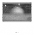
- the first irradiation area formed by the (1-2)-th light source is biased to a right side with respect to FIG. 6 .
- the second irradiation area formed by the (2-3)-th light source is biased to a left side with respect to FIG. 6 .
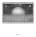
- symmetrical irradiation areas may be formed as illustrated in FIG. 8 .
- the symmetrical irradiation areas may correspond to a beam pattern required in the rules.
- the blinker and the daytime lamp may be disposed in one module to be adjacent to each other such that the lamp for a vehicle may become a module, a use efficiency of spaces of the vehicle may be increased and the lamps may be installed conveniently.
Landscapes
- Engineering & Computer Science (AREA)
- General Engineering & Computer Science (AREA)
- Physics & Mathematics (AREA)
- Optics & Photonics (AREA)
- Microelectronics & Electronic Packaging (AREA)
- Mechanical Engineering (AREA)
- General Physics & Mathematics (AREA)
- Non-Portable Lighting Devices Or Systems Thereof (AREA)
Abstract

Description
- This application claims the benefit of priority to
Korean Patent Application No. 10-2023-0002398, filed in the Korean Intellectual Property Office on January 6, 2023 - The present disclosure relates to a lamp for a vehicle, and a lamp assembly for a vehicle including the same.
- In general, a vehicle is equipped with various lamps. These lamps perform different functions including a lighting function for easily identifying a target located around the vehicle during nighttime driving, and a signal function for informing other vehicles or road users of a driving state or intended movement of the vehicle.
- For example, a low beam lamp is mainly directed to a lighting function, and is directed to a turn signal function commonly referred to as a blinker.
- In recent years, rules that force lamps to be turned on during daytimes have been newly made to reduce traffic accidents. Thus, daytime running lights (DRLs) are mounted on recently released vehicles.
- The low beam lamps, the blinkers, and the daytime lamps have different purposes, and all of them should be mounted in an interior of the vehicle. However, in the conventional technology, because the low beam lamps, the blinkers, and the daytime lamps should be disposed in individual lamp spaces, respectively, they occupy a large space and the sizes of the lamps has to be small.
- The present disclosure has been made to solve the above-mentioned problems occurring in the prior art while advantages achieved by the prior art are maintained intact.
- An aspect of the present disclosure provides a lamp for a vehicle, and a lamp assembly for a vehicle, which may implement low beam lamps, blinkers, and daytime lamps in one module.
- The technical problems to be solved by the present disclosure are not limited to the aforementioned problems, and any other technical problems not mentioned herein will be clearly understood from the following description by those skilled in the art to which the present disclosure pertains.
- According to an aspect of the present disclosure, a lamp for a vehicle includes a first light source that emits a first light along a first direction that is perpendicular to an upward/downward direction; a refractor that refracts the first light emitted from the first light source; a second light source that emits a second light toward the refractor along a second direction that crosses the first direction; and a third light source disposed adjacent to the second light source, and that emits a third light toward the refractor along the second direction.
- In another example, a direction that is perpendicular to the first direction is defined as a third direction. The second light source and the third light source may be arranged along the third direction.
- In another example, the lamp may further include a first collimator to collimate the first light, a second collimator disposed in the second direction of the second light source, and that collimates the second light, and a third collimator disposed in the second direction of the third light source, and that collimates the third light.
- In another example, the second collimator and the third collimator may have symmetrical shapes.
- In another example, the second collimator may have an arc shape, of which a central angle is 180 degrees or more when viewed along the second direction, and a string of the arc shape may have a shape that extends in a direction that is perpendicular to the second direction and the third direction. The string of an arc refers to the line segment that connects the endpoints of the arc. An arc has a curvature, and the string is the straight line that spans the length of that arc. The string can also be considered the base for the arc.
- In another example, the second collimator may be formed to be convex along an opposite direction to the second direction.
- In another example, the lamp may further include a coupling part, with which the second collimator and the third collimator are coupled to each other, an overlapping junction at which the second collimator and the third collimator overlap each other, may be disposed on a central side of the coupling part.
- In another example, the refractor may include a first input area, to which the first light is input, a second input area, to which the second light and the third light are input, and an output area, from which the first to third lights are output, and the second input area may be formed between the first input area and the output area.
- In another example, the refractor may include a first shield area that interrupts a portion of the first light that passed through the first input area, and the second light source and the third light source may be disposed on a lower side of the first shield area.
- In another example, the refractor further may include a second shield area that interrupts a portion of the second light and a portion of the third light, which passed through the second input area.
- In another example, the lamp may further include a first collimator disposed in the first direction of the third light source, and that collimates the first light, and the first collimator may be spaced apart from the first input area along the first direction.
- According to another aspect of the present disclosure, a lamp assembly for a vehicle includes a first lamp, and a second lamp disposed on a lower side of the first lamp, the first lamp includes a (1-1)-th light source that emits a (1-1)-th light along a (1-1)-th direction that is horizontal, a first refractor that refracts the (1-1)-th light emitted from the (1-1)-th light source, a (1-2)-th light source that emits a (1-2)-th light toward the first refractor along a second direction that crosses the first direction, and a (1-3)-th light source disposed adjacent to the (1-2)-th light source, and that emits a (1-3)-th light toward the first refractor along the second direction, the second lamp includes a (2-1)-th light source that emits a (2-1)-th light along the first direction, a second refractor that refracts the (2-1)-th light emitted from the (2-1)-th light source, a (2-2)-th light source that emits a (2-2)-th light toward the second refractor along the second direction, and a (2-3)-th light source disposed adjacent to the (2-2)-th light source, and that emits a (2-3)-th light toward the second refractor along the second direction, the (1-2)-th light corresponds to the (2-3)-th light, and the (1-3)-th light corresponds to the (2-2)-th light.
- In another example, the first lamp may include a (1-2)-th collimator disposed in the second direction of the (1-2)-th light source, and that collimates the (1-2)-th light, and a (1-3)-th collimator disposed in the second direction of the (1-3)-th light source, and that collimates the (1-3)-th light, the second lamp may include a (2-2)-th collimator disposed in the second direction of the (2-2)-th light source, and that collimates the (2-2)-th light, and a (2-3)-th collimator disposed in the second direction of the (2-3)-th light source, and that collimates the (2-3)-th light, the (1-2)-th collimator may corresponds to the (2-3)-th collimator, and the (1-3)-th collimator may correspond to the (2-2)-th collimator.
- The above and other objects, features and advantages of the present disclosure will be more apparent from the following detailed description taken in conjunction with the accompanying drawings:
-
FIG. 1 is a view conceptually illustrating a lamp for a vehicle according to an embodiment of the present disclosure; -
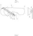
FIG. 2 is a view illustrating an appearance of the lamp for a vehicle ofFIG. 1 , when viewed from another direction; -
FIG. 3 is a perspective view illustrating a second collimator and a third collimator; -
FIG. 4 is a view of a second collimator and a third collimator, when viewed along a second direction; -
FIG. 5 is a view conceptually illustrating a lamp assembly for a vehicle according to an embodiment of the present disclosure; -
FIG. 6 illustrates a first irradiation area of a (1-2)-th light irradiated by a (1-2)-th light source of a first lamp; -
FIG. 7 illustrates a second irradiation area of a (2-3)-th light irradiated by a (2-3)-th light source of a first lamp; and -
FIG. 8 illustrates an appearance, in which the first irradiation area of the (1-2)-th light irradiated by the (1-2)-th light source of the first lamp and the second irradiation area of the (2-3)-th light irradiated by the (2-3)-th light source of the second lamp overlap each other. - Hereinafter, some embodiments of the present disclosure will be described in detail with reference to the exemplary drawings. Throughout the specification, it is noted that the same or like reference numerals denote the same or like components even though they are provided in different drawings. Further, in the following description of the present disclosure, a detailed description of known functions and configurations incorporated herein will be omitted when it may make the subject matter of the present disclosure rather unclear.
- A lamp according to an embodiment of the present disclosure relates to a lamp that may be used in a vehicle. As an example, the lamp for a vehicle may be a headlamp. As an example, the lamp for a vehicle may be a lamp for irradiating a low beam. However, the present disclosure is not limited thereto, and it is apparent that the lamp according to the embodiment of the present disclosure may be applied to lamps of various fields, such as a rear lamp.
- Forward/rearward, leftward/rightward, and upward/downward directions in the specification are referred for convenience of description, and may be directions that are perpendicular to each other. However, the directions are determined relative to a direction, in which the lamp is arranged, and the upward/downward direction does not always mean a vertical direction.
-
FIG. 1 is a view conceptually illustrating a lamp for a vehicle according to an embodiment of the present disclosure.FIG. 2 is a view illustrating an appearance of the lamp for a vehicle ofFIG. 1 , when viewed from another direction. - The lamp for a vehicle according to an embodiment of the present disclosure may include a
refractor 10, afirst light source 20, a second light source30, and athird light source 40. Therefractor 10 may be configured to refract lights emitted from the first tothird light source first light source 20 may emit a first light along a first direction D1 that is perpendicular to the upward/downward direction. As an example, the first direction D1 may be a forward direction. The first light may be a low beam. Therefractor 10 may be configured to refract the first light emitted from thefirst light source 20. - The
second light source 30 may emit a second light toward therefraction 10 along a second direction D2 that is a direction that crosses the first direction D1. The second light may be a daytime lamp. Thethird light source 40 may be disposed adjacent to thesecond light source 30, and may emit a third light toward therefraction 10 along the second direction D2. The third light may be a blinker. - According to the present disclosure, because the blinker and the daytime lamp may be disposed in one module to be adjacent to each other such that the lamp for a vehicle may become a module, a use efficiency of spaces of the vehicle may be increased and the lamps may be installed conveniently.
- Hereinafter, a detailed form of the lamp for a vehicle having the features will be described in detail. Assume that a direction that is perpendicular to the first direction D1 is defined as a third direction D3. The second
light source 30 and the thirdlight source 40 may be arranged along the third direction D3. As an example, the secondlight source 30 may be disposed in the third direction D3 of the thirdlight source 40. As another example, the thirdlight source 40 may be disposed in the third direction D3 of the secondlight source 30. Then, they may be spaced apart from each other. - The lamp for a vehicle according to an embodiment of the present disclosure may include a
first collimator 50, asecond collimator 60, and athird collimator 70. Thefirst collimator 50 may be disposed in the first direction D1 of thefirst light source 20, and may be configured to collimate the first light. -
FIG. 3 is a perspective view illustrating a second collimator and a third collimator.FIG. 4 is a view of a second collimator and a third collimator, when viewed along a second direction. Thesecond collimator 60 may be disposed in the second direction D2 of the secondlight source 30 and may be configured to collimate the second light. Thethird collimator 70 may be disposed in the second direction D2 of the thirdlight source 40 and may be configured to collimate the third light. Thesecond collimator 60 and thethird collimator 70 may have symmetrical shapes. - As an example, when the
second collimator 60 is viewed along the second direction D2, it may have an arc shape, of which a central angle is 180 degrees or more. Then, a string of the arc shape may extend in a direction that is perpendicular to the second direction D2 and the third direction D3. Furthermore, thesecond collimator 60 may be formed to be convex along an opposite direction to the second direction D2. It may be understood that thesecond collimator 60 has a shape obtained by cutting a portion of a convex lens. - The second
light source 30 may be located at a site that is moved from a center point of the arc shape along an opposite direction of the second direction D2. - Likewise, when the
third collimator 70 is viewed along the second direction D2, it may have an arc shape, of which a central angle is 180 degrees or more. Then, a string of the arc shape may extend in a direction that is perpendicular to the second direction D2. Furthermore, thethird collimator 70 may be formed to be convex along an opposite direction to the second direction D2. It may be understood that thethird collimator 70 as a shape obtained by cutting a portion of a convex lens. - Meanwhile, the third
light source 40 may be located at a site that is moved from a center point of the arc shape along an opposite direction of the second direction D2. When the central angle of the arc shape is 180 degrees, locations of the secondlight source 30 and the thirdlight source 40 overlap each other. Accordingly, it is preferable that the central angle of the arc shape is 180 degrees or more. - The lamp for a vehicle according to an embodiment of the present disclosure may further include a
coupling part 80. Thecoupling part 80 may be a part, in which thesecond collimator 60 and thethird collimator 70 are coupled to each other. Ajunction 81 is where thesecond collimator 60 and thethird collimator 70 overlap each other. Thejunction 81 may be located at a central portion of thecoupling part 80. This may mean that the secondlight source 30 and the thirdlight source 40 may have corresponding locations at locations that are spaced apart from the center of thecoupling part 80 along the third direction D3 or an opposite direction thereto. - Next, a shape of the
refractor 10 will be described in detail. Therefractor 10 may include afirst input area 11, asecond input area 12, and anoutput area 13. Thefirst input area 11 may be an area, to which the first light is input. Thesecond input area 12 may be an area, to which the second light and the third light are input. Theoutput area 13 may be an area, from which the first tothird lights second input area 12 may be formed between thefirst input area 11 and theoutput area 13. - The
refractor 10 may include afirst shield area 14. Thefirst shield area 14 may be configured to interrupt a portion of the first light that passed through thefirst input area 11. The secondlight source 30 and the thirdlight source 40 may be disposed on a lower side of thefirst shield area 14. - The
refractor 10 may include asecond shield area 15. Thesecond shield area 15 may be configured to interrupt a portion of the second light and a portion of the third light, which passed through thesecond input area 12. - Hereinafter, the lamp assembly for a vehicle including the lamp for a vehicle will be described in detail with reference to the description of the above-described lamp for a vehicle.
FIG. 5 is a view conceptually illustrating the lamp assembly for a vehicle according to an embodiment of the present disclosure. For reference, illustration of the light sources is omitted inFIG. 5 to facilitate understanding. - Hereinafter, the lamp assembly for a vehicle will be described with reference to
FIG. 5 . Configurations that are the same as or correspond to those of the above-described lamp for a vehicle will be marked with the same or corresponding reference numerals, and a detailed description thereof will be omitted. - The lamp assembly for a vehicle according to an embodiment of the present disclosure may include a
first lamp 100 and asecond lamp 200. Thesecond lamp 200 may be disposed on a lower side of thefirst lamp 100. Here, it is apparent that the expression of thefirst lamp 100 and thesecond lamp 200 is not intended to limit the number of the lamps, and a plurality of lamps may be further included. Eachlamp - Thus, the
first lamp 100 may include afirst refractor 110, a (1-1)-th light source, a (1-2)-th light source, and a (1-3)-th light source. Thefirst refractor 110 may be configured to refract the light emitted from the (1-1)-th to (1-3)-th light sources. The (1-1)-th light source may emit a (1-1)-th light along the first direction D1. The (1-1)-th light may be a low beam. - The (1-2)-th light source may emit a (1-2)-th light toward the
first refractor 110 along the second direction D2. The (1-2)-th light may be a daytime lamp. The (1-3)-th light source may be disposed adjacent to the (1-2)-th light source, and may emit a (1-3)-th light toward thefirst refractor 110 along the second direction D2. The (1-3)-th light may be a blinker. - The
second lamp 200 may include asecond refractor 210, a (2-1)-th light source, a (2-2)-th light source, and a (2-3)-th light source. Thesecond refractor 210 may be configured to refract the light emitted from the (2-1)-th to (2-3)-th light sources. The (2-1)-th light source may emit a (2-1)-th light along the first direction D1. The (2-1)-th light may be a low beam. - The (2-2)-th light source may emit a (2-2)-th light toward the
second refractor 210 along the second direction D2. The (2-2)-th light may be a blinker. The (2-3)-th light source may be disposed adjacent to the (2-2)-th light source, and may emit a (2-3)-th light toward thesecond refractor 210 along the second direction D2. The (2-3)-th light may be a daytime lamp. - This means that the (1-2)-th light may correspond to the (2-3)-th light and the (1-3)-th light may correspond to the (2-2)-th light.
- The
first lamp 100 may include a (1-2)-th collimator 160 and a (1-3)-th collimator 170. The (1-2)-th collimator 160 may be disposed in the second direction D2 of the (1-2)-th light source, and may be configured to collimate the (1-2)-th light. The (1-3)-th collimator 170 may be disposed in the second direction D2 of the (1-3)-th light source, and may be configured to collimate the (1-3)-th light. - The
second lamp 200 may include a (2-2)-th collimator 260 and a (2-3)-th collimator 270. The (2-2)-th collimator 260 may be disposed in the second direction D2 of the (2-2)-th light source, and may be configured to collimate the (2-2)-th light. The (2-3)-th collimator 270 may be disposed in the second direction D2 of the (2-3)-th light source, and may be configured to collimate the (2-3)-th light. That is, as illustrated in the drawings, the (1-2)-th collimator 160 may correspond to the (2-3)-th collimator 270 and the (1-3)-th collimator 170 may correspond to the (2-2)-th collimator 260. -
FIG. 6 illustrates a first irradiation area of the (1-2)-th light irradiated by the (1-2)-th light source of the first lamp.FIG. 7 illustrates a second irradiation area of the (2-3)-th light irradiated by the (2-3)-th light source of the first lamp.FIG. 8 illustrates an appearance, in which the first irradiation area of the (1-2)-th light irradiated by the (1-2)-th light source of the first lamp and the second irradiation area of the (2-3)-th light irradiated by the (2-3)-th light source of the second lamp overlap each other. - As described above, in the lamp for a vehicle, the (1-2)-th light source and the (2-3)-th light source may be located at locations that are spaced apart from a central portion of the lamp in the third direction D3 or an opposite direction thereto. In detail, when the (1-2)-th light source is spaced apart from the central portion of the lamp along the third direction D3, the (2-3)-th light source may be spaced apart from the central portion of the lamp along the opposite direction to the third direction D3. Accordingly, when the (1-2)-th light is irradiated only by the (1-2)-th light source or the (2-3)-th light is irradiated only by the (2-3)-th light source, light that deviates from the central portion of the lamp is emitted.
- For example, in
FIG. 6 , the first irradiation area formed by the (1-2)-th light source is biased to a right side with respect toFIG. 6 . Furthermore, inFIG. 7 , the second irradiation area formed by the (2-3)-th light source is biased to a left side with respect toFIG. 6 . Accordingly, when the (1-2)-th light source and the (2-3)-th light source emit light at the same time, symmetrical irradiation areas may be formed as illustrated inFIG. 8 . The symmetrical irradiation areas may correspond to a beam pattern required in the rules. - According to the present disclosure, because the blinker and the daytime lamp may be disposed in one module to be adjacent to each other such that the lamp for a vehicle may become a module, a use efficiency of spaces of the vehicle may be increased and the lamps may be installed conveniently.
- The above description is a simple exemplification of the technical spirits of the present disclosure, and the present disclosure may be variously corrected and modified by those skilled in the art to which the present disclosure pertains without departing from the essential features of the present disclosure. Accordingly, the embodiments disclosed in the present disclosure are not provided to limit the technical spirits of the present disclosure but provided to describe the present disclosure, and the scope of the technical spirits of the present disclosure is not limited by the embodiments. Accordingly, the technical scope of the present disclosure should be construed by the attached claims, and all the technical spirits within the equivalent ranges fall within the scope of the present disclosure.
Claims (13)
- A lamp for a vehicle comprising:a first light source configured to emit a first light along a first direction perpendicular to an upward/downward direction;a refractor configured to refract the first light emitted from the first light source;a second light source configured to emit a second light toward the refractor along a second direction crossing the first direction; anda third light source disposed adjacent to the second light source, and configured to emit a third light toward the refractor along the second direction.
- The lamp of claim 1, wherein:
the second light source and the third light source are arranged along a third direction perpendicular to the first direction. - The lamp of claim 2, further comprising:a first collimator to collimate the first light;a second collimator disposed in the second direction of the second light source, and configured to collimate the second light; anda third collimator disposed in the second direction of the third light source, and configured to collimate the third light.
- The lamp of claim 3, wherein the second collimator and the third collimator have symmetrical shapes.
- The lamp of claim 4, wherein the second collimator has an arc shape, of which a central angle is 180 degrees or more when viewed along the second direction, and a string of the arc shape has a shape that extends in a direction that is perpendicular to the second direction and the third direction.
- The lamp of claim 5, wherein the second collimator is formed to be convex along a direction opposite to the second direction.
- The lamp of any one of claims 3 to 6, further comprising:a coupling part, with which the second collimator and the third collimator are coupled to each other,an overlapping junction at which the second collimator and the third collimator overlap each other is disposed at a central portion of the coupling part.
- The lamp of claim 3, wherein the refractor includes:a first input area to which the first light is input;a second input area to which the second light and the third light are input; andan output area from which the first to third lights are output;wherein the second input area is formed between the first input area and the output area.
- The lamp of claim 8, wherein the refractor includes:a first shield area configured to interrupt a portion of the first light passing through the first input area,wherein the second light source and the third light source are disposed on a lower side of the first shield area.
- The lamp of claim 9, wherein the refractor further includes
a second shield area configured to interrupt a portion of the second light and a portion of the third light passing through the second input area. - The lamp of any one of claims 8 to 10, further comprisingthe first collimator disposed in the first direction of the third light source and configured to collimate the first light,wherein the first collimator is spaced apart from the first input area along the first direction.
- A lamp assembly for a vehicle comprising:a first lamp; anda second lamp disposed on a lower side of the first lamp,wherein the first lamp includes:a (1-1)-th light source configured to emit a (1-1)-th light along a (1-1)-th direction perpendicular to an upward/downward direction;a first refractor configured to refract the (1-1)-th light emitted from the (1-1)-th light source;a (1-2)-th light source configured to emit a (1-2)-th light toward the first refractor along a second direction crossing the first direction; anda (1-3)-th light source disposed adjacent to the (1-2)-th light source, and configured to emit a (1-3)-th light toward the first refractor along the second direction,wherein the second lamp includes:a (2-1)-th light source configured to emit a (2-1)-th light along the first direction;a second refractor configured to refract the (2-1)-th light emitted from the (2-1)-th light source;a (2-2)-th light source configured to emit a (2-2)-th light toward the second refractor along the second direction; anda (2-3)-th light source disposed adjacent to the (2-2)-th light source, and configured to emit a (2-3)-th light toward the second refractor along the second direction,wherein the (1-2)-th light corresponds to the (2-3)-th light, andwherein the (1-3)-th light corresponds to the (2-2)-th light.
- The lamp assembly of claim 12, wherein the first lamp includes:a (1-2)-th collimator disposed in the second direction of the (1-2)-th light source, and configured to collimate the (1-2)-th light; anda (1-3)-th collimator disposed in the second direction of the (1-3)-th light source, and configured to collimate the (1-3)-th light,wherein the second lamp includes:a (2-2)-th collimator disposed in the second direction of the (2-2)-th light source, and configured to collimate the (2-2)-th light; anda (2-3)-th collimator disposed in the second direction of the (2-3)-th light source, and configured to collimate the (2-3)-th light,wherein the (1-2)-th collimator corresponds to the (2-3)-th collimator, andwherein the (1-3)-th collimator corresponds to the (2-2)-th collimator
Applications Claiming Priority (1)
| Application Number | Priority Date | Filing Date | Title |
|---|---|---|---|
| KR1020230002398A KR20240110386A (en) | 2023-01-06 | 2023-01-06 | Lamp for car and lamp assembly for car |
Publications (2)
| Publication Number | Publication Date |
|---|---|
| EP4397901A1 true EP4397901A1 (en) | 2024-07-10 |
| EP4397901B1 EP4397901B1 (en) | 2025-12-03 |
Family
ID=86942620
Family Applications (1)
| Application Number | Title | Priority Date | Filing Date |
|---|---|---|---|
| EP23180818.9A Active EP4397901B1 (en) | 2023-01-06 | 2023-06-22 | Lamp and lamp assembly for vehicle |
Country Status (5)
| Country | Link |
|---|---|
| US (2) | US12044375B1 (en) |
| EP (1) | EP4397901B1 (en) |
| JP (1) | JP2024097739A (en) |
| KR (1) | KR20240110386A (en) |
| CN (1) | CN118309952A (en) |
Citations (6)
| Publication number | Priority date | Publication date | Assignee | Title |
|---|---|---|---|---|
| EP3508777A1 (en) * | 2016-09-02 | 2019-07-10 | Koito Manufacturing Co., Ltd. | Vehicular lamp |
| EP3907427A1 (en) * | 2019-02-25 | 2021-11-10 | Hasco Vision Technology Co., Ltd. | High and low beam integrated vehicle lamp lighting device, vehicle lamp, and vehicle |
| EP3929034A1 (en) * | 2020-06-23 | 2021-12-29 | Stanley Electric Co., Ltd. | Vehicle lamp with a light guide |
| EP4006408A1 (en) * | 2020-03-09 | 2022-06-01 | Hasco Vision Technology Co., Ltd. | Vehicle light optical element assembly, vehicle lighting device, vehicle light and vehicle |
| DE102021122111A1 (en) * | 2021-02-01 | 2022-08-04 | Hyundai Mobis Co., Ltd. | LAMP MODULE FOR A VEHICLE, AND LAMP FOR A VEHICLE WITH SUCH LAMP MODULE |
| US11754245B1 (en) * | 2022-06-13 | 2023-09-12 | Hyundai Mobis Co., Ltd. | Lamp module for vehicle and lamp for vehicle including the same |
Family Cites Families (8)
| Publication number | Priority date | Publication date | Assignee | Title |
|---|---|---|---|---|
| DE102011013211B4 (en) * | 2011-03-05 | 2012-12-06 | Automotive Lighting Reutlingen Gmbh | Motor vehicle headlight with a multi-function projection module |
| AT512569B1 (en) * | 2012-03-07 | 2014-09-15 | Zizala Lichtsysteme Gmbh | Lighting device for a motor vehicle |
| JP5911397B2 (en) * | 2012-07-31 | 2016-04-27 | スタンレー電気株式会社 | Vehicle headlamp |
| JP6380846B2 (en) * | 2014-02-24 | 2018-08-29 | パナソニックIpマネジメント株式会社 | LIGHTING DEVICE AND AUTOMOBILE HAVING LIGHTING DEVICE |
| CN108603644B (en) * | 2016-01-13 | 2020-11-06 | 三菱电机株式会社 | Headlamp Modules and Headlamp Units |
| AT518552B1 (en) * | 2016-08-19 | 2017-11-15 | Zkw Group Gmbh | Lighting unit for a motor vehicle headlight for generating at least two light distributions |
| FR3056688B1 (en) * | 2016-09-26 | 2018-11-02 | Valeo Vision | BI-FUNCTION LIGHTING MODULE IN TRANSPARENT MATERIAL |
| FR3075926B1 (en) * | 2017-12-21 | 2021-04-02 | Valeo Vision | AUTOMOTIVE VEHICLE LIGHTING DEVICE |
-
2023
- 2023-01-06 KR KR1020230002398A patent/KR20240110386A/en active Pending
- 2023-06-22 EP EP23180818.9A patent/EP4397901B1/en active Active
- 2023-06-23 US US18/340,131 patent/US12044375B1/en active Active
- 2023-07-04 JP JP2023109902A patent/JP2024097739A/en active Pending
- 2023-07-14 CN CN202310869941.8A patent/CN118309952A/en active Pending
-
2024
- 2024-06-21 US US18/749,800 patent/US12467597B2/en active Active
Patent Citations (6)
| Publication number | Priority date | Publication date | Assignee | Title |
|---|---|---|---|---|
| EP3508777A1 (en) * | 2016-09-02 | 2019-07-10 | Koito Manufacturing Co., Ltd. | Vehicular lamp |
| EP3907427A1 (en) * | 2019-02-25 | 2021-11-10 | Hasco Vision Technology Co., Ltd. | High and low beam integrated vehicle lamp lighting device, vehicle lamp, and vehicle |
| EP4006408A1 (en) * | 2020-03-09 | 2022-06-01 | Hasco Vision Technology Co., Ltd. | Vehicle light optical element assembly, vehicle lighting device, vehicle light and vehicle |
| EP3929034A1 (en) * | 2020-06-23 | 2021-12-29 | Stanley Electric Co., Ltd. | Vehicle lamp with a light guide |
| DE102021122111A1 (en) * | 2021-02-01 | 2022-08-04 | Hyundai Mobis Co., Ltd. | LAMP MODULE FOR A VEHICLE, AND LAMP FOR A VEHICLE WITH SUCH LAMP MODULE |
| US11754245B1 (en) * | 2022-06-13 | 2023-09-12 | Hyundai Mobis Co., Ltd. | Lamp module for vehicle and lamp for vehicle including the same |
Also Published As
| Publication number | Publication date |
|---|---|
| US20240230045A1 (en) | 2024-07-11 |
| EP4397901B1 (en) | 2025-12-03 |
| KR20240110386A (en) | 2024-07-15 |
| CN118309952A (en) | 2024-07-09 |
| US12044375B1 (en) | 2024-07-23 |
| JP2024097739A (en) | 2024-07-19 |
| US12467597B2 (en) | 2025-11-11 |
| US20240337359A1 (en) | 2024-10-10 |
Similar Documents
| Publication | Publication Date | Title |
|---|---|---|
| EP1794490B1 (en) | Led collimator element with a semiparabolic reflector | |
| KR100706061B1 (en) | Vehicular lamp | |
| CN111380026A (en) | Vehicle lamp | |
| CN114383110A (en) | Vehicle lamp | |
| EP1527301B1 (en) | Illumination system | |
| WO2022030387A1 (en) | Vehicle lighting having function for drawing on road surface | |
| EP4397901A1 (en) | Lamp and lamp assembly for vehicle | |
| JPH0797442B2 (en) | Lighting lamp for passing beam or fog beam of automobile | |
| KR101486818B1 (en) | Lamp for vehicle | |
| KR102405441B1 (en) | Lamp for vehicle | |
| US20230324022A1 (en) | Beamshaping Waveguide for Headlights | |
| KR102522911B1 (en) | Lamp for vehicle | |
| US11300265B2 (en) | Lamp for automobile and automobile including the same | |
| CN106969329A (en) | Optical deflecting device and illumination and/or signal indicating device | |
| KR102907160B1 (en) | Lamp for vehicle | |
| CN110486689A (en) | Illumination or signal indicating device and motor vehicles | |
| KR102673137B1 (en) | Lamp of vehicle | |
| EP4400366A1 (en) | Lamp for vehicle | |
| CN223677613U (en) | Vehicle driving lamp and vehicle driving lamp mask | |
| US12025286B2 (en) | Lamp for vehicle | |
| KR20150072085A (en) | Lamp for vehicle | |
| US20250264201A1 (en) | Vehicle Headlamp for High Mount Applications | |
| KR20230150528A (en) | Lamp for vehicle | |
| KR20230045959A (en) | Automotive lamp | |
| KR20230150526A (en) | Lamp for vehicle |
Legal Events
| Date | Code | Title | Description |
|---|---|---|---|
| PUAI | Public reference made under article 153(3) epc to a published international application that has entered the european phase |
Free format text: ORIGINAL CODE: 0009012 |
|
| STAA | Information on the status of an ep patent application or granted ep patent |
Free format text: STATUS: THE APPLICATION HAS BEEN PUBLISHED |
|
| AK | Designated contracting states |
Kind code of ref document: A1 Designated state(s): AL AT BE BG CH CY CZ DE DK EE ES FI FR GB GR HR HU IE IS IT LI LT LU LV MC ME MK MT NL NO PL PT RO RS SE SI SK SM TR |
|
| STAA | Information on the status of an ep patent application or granted ep patent |
Free format text: STATUS: REQUEST FOR EXAMINATION WAS MADE |
|
| 17P | Request for examination filed |
Effective date: 20250109 |
|
| STAA | Information on the status of an ep patent application or granted ep patent |
Free format text: STATUS: EXAMINATION IS IN PROGRESS |
|
| 17Q | First examination report despatched |
Effective date: 20250305 |
|
| GRAP | Despatch of communication of intention to grant a patent |
Free format text: ORIGINAL CODE: EPIDOSNIGR1 |
|
| STAA | Information on the status of an ep patent application or granted ep patent |
Free format text: STATUS: GRANT OF PATENT IS INTENDED |
|
| INTG | Intention to grant announced |
Effective date: 20250707 |
|
| GRAS | Grant fee paid |
Free format text: ORIGINAL CODE: EPIDOSNIGR3 |
|
| GRAA | (expected) grant |
Free format text: ORIGINAL CODE: 0009210 |
|
| STAA | Information on the status of an ep patent application or granted ep patent |
Free format text: STATUS: THE PATENT HAS BEEN GRANTED |
|
| P01 | Opt-out of the competence of the unified patent court (upc) registered |
Free format text: CASE NUMBER: UPC_APP_0010799_4397901/2025 Effective date: 20251022 |
|
| AK | Designated contracting states |
Kind code of ref document: B1 Designated state(s): AL AT BE BG CH CY CZ DE DK EE ES FI FR GB GR HR HU IE IS IT LI LT LU LV MC ME MK MT NL NO PL PT RO RS SE SI SK SM TR |
|
| REG | Reference to a national code |
Ref country code: CH Ref legal event code: F10 Free format text: ST27 STATUS EVENT CODE: U-0-0-F10-F00 (AS PROVIDED BY THE NATIONAL OFFICE) Effective date: 20251203 Ref country code: GB Ref legal event code: FG4D |
|
| REG | Reference to a national code |
Ref country code: DE Ref legal event code: R096 Ref document number: 602023009177 Country of ref document: DE |
|
| REG | Reference to a national code |
Ref country code: IE Ref legal event code: FG4D |
|
| REG | Reference to a national code |
Ref country code: NL Ref legal event code: MP Effective date: 20251203 |
|
| PG25 | Lapsed in a contracting state [announced via postgrant information from national office to epo] |
Ref country code: ES Free format text: LAPSE BECAUSE OF FAILURE TO SUBMIT A TRANSLATION OF THE DESCRIPTION OR TO PAY THE FEE WITHIN THE PRESCRIBED TIME-LIMIT Effective date: 20251203 |
|
| REG | Reference to a national code |
Ref country code: LT Ref legal event code: MG9D |
|
| PG25 | Lapsed in a contracting state [announced via postgrant information from national office to epo] |
Ref country code: NO Free format text: LAPSE BECAUSE OF FAILURE TO SUBMIT A TRANSLATION OF THE DESCRIPTION OR TO PAY THE FEE WITHIN THE PRESCRIBED TIME-LIMIT Effective date: 20260303 |
|
| PG25 | Lapsed in a contracting state [announced via postgrant information from national office to epo] |
Ref country code: HR Free format text: LAPSE BECAUSE OF FAILURE TO SUBMIT A TRANSLATION OF THE DESCRIPTION OR TO PAY THE FEE WITHIN THE PRESCRIBED TIME-LIMIT Effective date: 20251203 Ref country code: FI Free format text: LAPSE BECAUSE OF FAILURE TO SUBMIT A TRANSLATION OF THE DESCRIPTION OR TO PAY THE FEE WITHIN THE PRESCRIBED TIME-LIMIT Effective date: 20251203 |
|
| PG25 | Lapsed in a contracting state [announced via postgrant information from national office to epo] |
Ref country code: RS Free format text: LAPSE BECAUSE OF FAILURE TO SUBMIT A TRANSLATION OF THE DESCRIPTION OR TO PAY THE FEE WITHIN THE PRESCRIBED TIME-LIMIT Effective date: 20260303 |
|
| PG25 | Lapsed in a contracting state [announced via postgrant information from national office to epo] |
Ref country code: PL Free format text: LAPSE BECAUSE OF FAILURE TO SUBMIT A TRANSLATION OF THE DESCRIPTION OR TO PAY THE FEE WITHIN THE PRESCRIBED TIME-LIMIT Effective date: 20251203 |
|
| PG25 | Lapsed in a contracting state [announced via postgrant information from national office to epo] |
Ref country code: LV Free format text: LAPSE BECAUSE OF FAILURE TO SUBMIT A TRANSLATION OF THE DESCRIPTION OR TO PAY THE FEE WITHIN THE PRESCRIBED TIME-LIMIT Effective date: 20251203 |