EP1527301B1 - Illumination system - Google Patents
Illumination system Download PDFInfo
- Publication number
- EP1527301B1 EP1527301B1 EP03738397A EP03738397A EP1527301B1 EP 1527301 B1 EP1527301 B1 EP 1527301B1 EP 03738397 A EP03738397 A EP 03738397A EP 03738397 A EP03738397 A EP 03738397A EP 1527301 B1 EP1527301 B1 EP 1527301B1
- Authority
- EP
- European Patent Office
- Prior art keywords
- illumination system
- light source
- optical axis
- light
- reflector segments
- Prior art date
- Legal status (The legal status is an assumption and is not a legal conclusion. Google has not performed a legal analysis and makes no representation as to the accuracy of the status listed.)
- Expired - Lifetime
Links
- 238000005286 illumination Methods 0.000 title claims abstract description 51
- 230000003287 optical effect Effects 0.000 claims abstract description 38
- 230000004888 barrier function Effects 0.000 claims abstract description 3
- 239000013307 optical fiber Substances 0.000 claims description 6
- 239000000835 fiber Substances 0.000 claims description 4
- 230000004313 glare Effects 0.000 description 12
- 239000002184 metal Substances 0.000 description 2
- 238000002310 reflectometry Methods 0.000 description 2
- 239000000758 substrate Substances 0.000 description 2
- 244000025254 Cannabis sativa Species 0.000 description 1
- 239000000446 fuel Substances 0.000 description 1
- 229910001507 metal halide Inorganic materials 0.000 description 1
- 150000005309 metal halides Chemical class 0.000 description 1
- 230000007704 transition Effects 0.000 description 1
Images


Classifications
-
- F—MECHANICAL ENGINEERING; LIGHTING; HEATING; WEAPONS; BLASTING
- F21—LIGHTING
- F21S—NON-PORTABLE LIGHTING DEVICES; SYSTEMS THEREOF; VEHICLE LIGHTING DEVICES SPECIALLY ADAPTED FOR VEHICLE EXTERIORS
- F21S41/00—Illuminating devices specially adapted for vehicle exteriors, e.g. headlamps
- F21S41/10—Illuminating devices specially adapted for vehicle exteriors, e.g. headlamps characterised by the light source
- F21S41/14—Illuminating devices specially adapted for vehicle exteriors, e.g. headlamps characterised by the light source characterised by the type of light source
- F21S41/141—Light emitting diodes [LED]
- F21S41/143—Light emitting diodes [LED] the main emission direction of the LED being parallel to the optical axis of the illuminating device
-
- F—MECHANICAL ENGINEERING; LIGHTING; HEATING; WEAPONS; BLASTING
- F21—LIGHTING
- F21S—NON-PORTABLE LIGHTING DEVICES; SYSTEMS THEREOF; VEHICLE LIGHTING DEVICES SPECIALLY ADAPTED FOR VEHICLE EXTERIORS
- F21S41/00—Illuminating devices specially adapted for vehicle exteriors, e.g. headlamps
- F21S41/20—Illuminating devices specially adapted for vehicle exteriors, e.g. headlamps characterised by refractors, transparent cover plates, light guides or filters
- F21S41/24—Light guides
-
- F—MECHANICAL ENGINEERING; LIGHTING; HEATING; WEAPONS; BLASTING
- F21—LIGHTING
- F21S—NON-PORTABLE LIGHTING DEVICES; SYSTEMS THEREOF; VEHICLE LIGHTING DEVICES SPECIALLY ADAPTED FOR VEHICLE EXTERIORS
- F21S41/00—Illuminating devices specially adapted for vehicle exteriors, e.g. headlamps
- F21S41/30—Illuminating devices specially adapted for vehicle exteriors, e.g. headlamps characterised by reflectors
- F21S41/32—Optical layout thereof
- F21S41/321—Optical layout thereof the reflector being a surface of revolution or a planar surface, e.g. truncated
-
- F—MECHANICAL ENGINEERING; LIGHTING; HEATING; WEAPONS; BLASTING
- F21—LIGHTING
- F21S—NON-PORTABLE LIGHTING DEVICES; SYSTEMS THEREOF; VEHICLE LIGHTING DEVICES SPECIALLY ADAPTED FOR VEHICLE EXTERIORS
- F21S41/00—Illuminating devices specially adapted for vehicle exteriors, e.g. headlamps
- F21S41/30—Illuminating devices specially adapted for vehicle exteriors, e.g. headlamps characterised by reflectors
- F21S41/32—Optical layout thereof
- F21S41/322—Optical layout thereof the reflector using total internal reflection
-
- F—MECHANICAL ENGINEERING; LIGHTING; HEATING; WEAPONS; BLASTING
- F21—LIGHTING
- F21S—NON-PORTABLE LIGHTING DEVICES; SYSTEMS THEREOF; VEHICLE LIGHTING DEVICES SPECIALLY ADAPTED FOR VEHICLE EXTERIORS
- F21S41/00—Illuminating devices specially adapted for vehicle exteriors, e.g. headlamps
- F21S41/30—Illuminating devices specially adapted for vehicle exteriors, e.g. headlamps characterised by reflectors
- F21S41/32—Optical layout thereof
- F21S41/33—Multi-surface reflectors, e.g. reflectors with facets or reflectors with portions of different curvature
- F21S41/331—Multi-surface reflectors, e.g. reflectors with facets or reflectors with portions of different curvature the reflector consisting of complete annular areas
- F21S41/332—Multi-surface reflectors, e.g. reflectors with facets or reflectors with portions of different curvature the reflector consisting of complete annular areas with continuity at the junction between adjacent areas
-
- F—MECHANICAL ENGINEERING; LIGHTING; HEATING; WEAPONS; BLASTING
- F21—LIGHTING
- F21S—NON-PORTABLE LIGHTING DEVICES; SYSTEMS THEREOF; VEHICLE LIGHTING DEVICES SPECIALLY ADAPTED FOR VEHICLE EXTERIORS
- F21S41/00—Illuminating devices specially adapted for vehicle exteriors, e.g. headlamps
- F21S41/30—Illuminating devices specially adapted for vehicle exteriors, e.g. headlamps characterised by reflectors
- F21S41/32—Optical layout thereof
- F21S41/33—Multi-surface reflectors, e.g. reflectors with facets or reflectors with portions of different curvature
- F21S41/331—Multi-surface reflectors, e.g. reflectors with facets or reflectors with portions of different curvature the reflector consisting of complete annular areas
- F21S41/333—Multi-surface reflectors, e.g. reflectors with facets or reflectors with portions of different curvature the reflector consisting of complete annular areas with discontinuity at the junction between adjacent areas
-
- F—MECHANICAL ENGINEERING; LIGHTING; HEATING; WEAPONS; BLASTING
- F21—LIGHTING
- F21S—NON-PORTABLE LIGHTING DEVICES; SYSTEMS THEREOF; VEHICLE LIGHTING DEVICES SPECIALLY ADAPTED FOR VEHICLE EXTERIORS
- F21S41/00—Illuminating devices specially adapted for vehicle exteriors, e.g. headlamps
- F21S41/30—Illuminating devices specially adapted for vehicle exteriors, e.g. headlamps characterised by reflectors
- F21S41/32—Optical layout thereof
- F21S41/33—Multi-surface reflectors, e.g. reflectors with facets or reflectors with portions of different curvature
- F21S41/334—Multi-surface reflectors, e.g. reflectors with facets or reflectors with portions of different curvature the reflector consisting of patch like sectors
-
- F—MECHANICAL ENGINEERING; LIGHTING; HEATING; WEAPONS; BLASTING
- F21—LIGHTING
- F21S—NON-PORTABLE LIGHTING DEVICES; SYSTEMS THEREOF; VEHICLE LIGHTING DEVICES SPECIALLY ADAPTED FOR VEHICLE EXTERIORS
- F21S41/00—Illuminating devices specially adapted for vehicle exteriors, e.g. headlamps
-
- F—MECHANICAL ENGINEERING; LIGHTING; HEATING; WEAPONS; BLASTING
- F21—LIGHTING
- F21W—INDEXING SCHEME ASSOCIATED WITH SUBCLASSES F21K, F21L, F21S and F21V, RELATING TO USES OR APPLICATIONS OF LIGHTING DEVICES OR SYSTEMS
- F21W2102/00—Exterior vehicle lighting devices for illuminating purposes
- F21W2102/10—Arrangement or contour of the emitted light
- F21W2102/13—Arrangement or contour of the emitted light for high-beam region or low-beam region
- F21W2102/135—Arrangement or contour of the emitted light for high-beam region or low-beam region the light having cut-off lines, i.e. clear borderlines between emitted regions and dark regions
-
- F—MECHANICAL ENGINEERING; LIGHTING; HEATING; WEAPONS; BLASTING
- F21—LIGHTING
- F21Y—INDEXING SCHEME ASSOCIATED WITH SUBCLASSES F21K, F21L, F21S and F21V, RELATING TO THE FORM OR THE KIND OF THE LIGHT SOURCES OR OF THE COLOUR OF THE LIGHT EMITTED
- F21Y2115/00—Light-generating elements of semiconductor light sources
- F21Y2115/10—Light-emitting diodes [LED]
Definitions
- the invention relates to a road illumination system according to the preamble of claim 1.
- a vehicle headlamp comprising such an illumination system is known from US Patent 5 361 193.
- the known vehicle headlamp comprises as light source a discharge lamp generating an arc disposed along an optical axis and comprises a reflecting surface comprising three reflecting sectors arranged around the optical axis.
- the reflecting sectors consist of two paraboloid-of-revolution sectors and one additional especially-shaped sector formed as a collection of intersecting lines obtained by cutting an imaginary paraboloid of revolution.
- a disadvantage of the known illumination system is that the cut-off between the illuminated area and the glare area of the light beam leaves is not as sharp as desired.
- US-A-5580156 shows a road illumination system according to the preamble of claim 1.
- an illumination system of the kind mentioned in the opening paragraph is for this purpose characterized by the characterizing part of claim 1.
- an imaginary plane is projected perpendicular to the central optical axis of the illumination system. This imaginary plane intersects the central optical axis at the location of the focus point of an imaginary reflector formed by the parabolically-shaped reflector segments in a situation in which the optical axes of the reflector segments would coincide with the central optical axis.
- the emission window of the light source is located in the imaginary plane and light is emitted from the emission window at one side of the imaginary plane only. No light is emitted by the light source at the backside of the imaginary plane.
- light from the light source is emitted only in the forward direction and reflected by the parabolically-shaped reflector segments which are positioned such that the segment optical axis substantially intersects with an edge of the light source.
- No light is directed in the backwards direction and reflected by the more central parts of the parabolically-shaped reflector segments.
- the inventors have had the insight that by applying a light source emitting light in half a hemisphere only in combination with the positioning of each reflector segment such that the segment optical axis substantially intersects with an edge of the light source, a sharp cut-off is obtained between the illuminated area and the glare area of the light beam emitted by the illumination system.
- a preferred embodiment of the illumination system according to the invention is characterized in that the light source is positioned substantially below a horizontal plane including the central optical axis.
- Light emitted by a light source according to this embodiment of the invention can after reflection on a reflector segment give rise to a light beam parallel to the central optical axis (this is the case for a portion of the light source which coincides with the central axis) or to a light beam which eventually intersects the horizontal plane (light is directed downwards to a surface of the road) but can not give rise to light in the glare area above the cut-off.
- Another preferred embodiment of the illumination system according to the invention is characterized in that one edge of the light source coincides substantially with the central optical axis.
- the light source is positioned below a horizontal plane including the central optical axis whereas one edge of the light source lies in the horizontal plan.
- Light emitted by a light source according to this embodiment of the invention can after reflection on a reflector segment give rise to a light beam parallel to the central optical axis or to a light beam which eventually intersects the horizontal plane (light is directed downwards) but not give rise to light in the glare area above the cut-off.
- a preferred embodiment of the illumination system according to the invention is characterized in that opposite reflector segments are positioned such that the optical axes of the reflector segments coincide with each other.
- Another preferred embodiment of the illumination system according to the invention is characterized in that the number of reflector segments is dividable by four. Preferably, the number of reflector segments is four, eight or twelve.
- a preferred embodiment of the illumination system according to the invention is characterized in that the reflector segments reflect light according to total internal reflection.
- the reflectivity of a reflector which operates according to the principle of total internal reflection (TIR) is more efficient because no light is lost upon reflection as compared to a reflector in which reflection is broad about by reflecting against a reflecting metal or reflecting metal-like layer on a substrate.
- the light source is a light-emitting diode (LED) or is an exit window of an optical fiber or a bundle of optical fibers.
- LED light-emitting diode
- the intensity distribution may, by way of example, be Lambertian around the central axis of the reflecting surface. LED's and optical fibres emit light in half a hemisphere only, while the light distribution of other light sources with a coil or with an arc is, in general, a torus-like shape.
- Figure 1 diagrammatically shows a perspective view of a part of a traffic road provided with an embodiment of the illumination system according to the invention.
- the road is divided in two lanes 1, 1' each with an adjacent (grass) verge 3, 3' and converging towards the horizon 2.
- the travel direction of a vehicle on one of the lanes 1 is indicated by a large arrow.
- the situation in Figure 1 refers to a right-lane system; in a left-lane system, the situation is similar but mirrored.
- the illumination system is provided on poles 5, 5', ... at the sides of the traffic route, in the example in the verges 3, 3' adjacent the traffic lanes 1, 1'.
- the poles 5, 5', ... are shown in one of the verges 3 only.
- the illumination system poles are provided for illuminating the opposite lane.
- the illumination system is provided on a crash barrier.
- the poles 5, 5', ... are of moderate height (typically at the same height as the headlights of a vehicle). In operation, light is emitted by the illumination system in the driving direction. In general, the poles 5, 5', ... direct the light in the same direction as the headlights of the vehicle (the direction of the light is indicated as the small arrows emerging from each of the poles 5, 5', ).
- An aim of the illumination system according to the invention is to increase the visibility of small objects on the road.
- the illumination system is configured such that projecting light on the opposite lane is largely avoided, because that will decrease the contrast with which the small objects are visible on that lane. In principle, it is not allowed that light from the illumination system reaches the eye of the driver on the opposing lane. This calls for a beam with a sharp cut-off near the centre line of the road lanes 1, 1' and to avoid unnecessary loss of light or light pollution, also a sharp cut-off near the horizon 2.
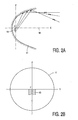
- Figure 2A shows a cross-section in the xz-plane of a light source positioned in a parabolically-shaped reflecting surface 11.
- Figure 2B shows a cross-section in the corresponding yz-plane.
- the xy-plane forms the horizontal plane; the z-direction is the vertical direction; the x-direction forms the central optical axis 18 of the illumination system coinciding with the direction in which the light is emitted by the illumination system.
- the light source 13 is positioned in the focal point (or focus) F of the reflecting surface 11.
- an upper edge of the light source 13 touches the horizontal xy-plane including the central optical axis 18.
- Light rays emerging from the light source and reflected by the reflecting surface are indicated with arrows in Figure 2A.
- light emitted by the light source 13 can after reflection on the reflecting surface 11 give rise to a light beam parallel to the central optical axis 18 or to a light beam which eventually intersects the central optical axis 18 and/or the horizontal xy-plane.
- light emitted by the light source 13 and reflected by the reflecting surface 11 can not contribute to the glare area above the cut-off.
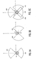
- FIG. 3A shows very schematically a front view of the illumination system according to the invention where the reflecting surface comprises two parabolically-shaped reflector segments 21N and 21 S. For the sake of clarity only parts of the reflector segments are shown.
- the reflector segment with reference numeral 21N is placed in front of the positive z-axis and will also be referred to the "north" reflector segment 21N.
- the reflector segment with reference numeral 21S is placed in front of the negative z-axis and will also be referred to the "south" reflector segment 21S.
- the north and south parabolically-shaped reflector segments 21N, 21S have been positioned such that the segment optical axis intersects the upper edge of the light source 13. Because said upper edge of the light source 13 lies on the y-axis, the segment optical axis for the north and south reflector segments coincides with the central optical axis of the reflecting surface.
- Figure 3B shows a front view of the illumination system according to the invention where the reflecting surface comprises two further parabolically-shaped reflector segments 21E and 21 W.
- the reflector segment with reference numeral 21E is placed in front of the positive y-axis and will also be referred to the "east" reflector segment 21E.
- the reflector segment with reference numeral 21W is placed in front of the negative y-axis and will also be referred to the "west” reflector segment 21 W.
- the east and west parabolically-shaped reflector segments 21E, 21 W have been positioned such that the segment optical axis intersects the lower edge of the light source 13. By placing the east and west reflector segments 21E, 21W along the lower edge of the light source 13, the desired sharp cut-off between the illuminated area and the glare area of the light beam is realized.
- Figure 3C shows a front view of the illumination system according to the invention where the reflecting surface comprises four parabolically-shaped reflector segments 21N, 21E, 21S and 21W. For the sake of clarity only parts of the reflector segments are shown. In Figure 3C the situations of Figure 3A and 3B have been superimposed.
- the north and south parabolically-shaped reflector segments 21N, 21 S have been positioned such that the segment optical axis intersects the upper edge of the light source 13.
- the east and west parabolically-shaped reflector segments 21 E, 21 W have been positioned such that the segment optical axis intersects the lower edge of the light source 13.
- Figure 4 shows a front view of an alternative embodiment of the illumination system according to the invention where the reflecting surface comprises eight parabolically-shaped reflector segments 31N, 3 1 S, 3 1 E, 31W, 31NE, 31 SW, 31NW, 31SE.
- the light source 13 and the focal point of the reflecting surface are also given.
- the north and south reflector segments are preferably in the center of the upper edge of the light source 13
- the east and west reflector segments are preferably in the center of the lower edge of the light source 13.
- the remaining reflector segments are positioned along the vertical edges of the light source 13, preferably, at regular intervals.
- the reflector segments of the reflect light according to total internal reflection.
- the reflectivity of a reflector which operates according to the principle of total internal reflection (TIR) is very efficient because no light is lost upon reflection as compared to a reflector in which reflection is broad about by reflecting against a reflecting metal or reflecting metal-like layer on a substrate.
- a preferred light source of the illumination system is a light-emitting diode (LED).
- the LED emits in operation substantially white light.
- the light source in the illumination system is an exit window of an optical fiber or a bundle of optical fibers.
- the fiber or fibers are powered by a so-called light engine.
Abstract
Description
- The invention relates to a road illumination system according to the preamble of
claim 1. - In the luminaire art, control of reflected energy has been carried out in various ways utilizing various types of light sources combined with various forms of (parabolic) reflecting surfaces. In automobile design there is a trend in streamlining the shape of the vehicle in order to satisfy requirements of high speed in combination with efficient fuel consumption. Such trend results in the front faces of automobiles to incline towards the horizontal plane necessitating the shape and the height of headlights to be adapted accordingly. As another trend, small metal halide lamps have attracted attention as light sources for such headlights.
- For the application of lamps in vehicle headlamps, requirements for automotive passing beam patterns have been laid down (e.g. for a person skilled in the art known as E/ECE/324 and E/ECE/TRANS505). These legal requirements prescribe, amongst others, the creation of a relatively sharp so-called cut-off between the illuminated area and the glare area of the light beam emitted by the vehicle headlamp measured at a certain distance of the vehicle. In fact, the requirements prescribe point/regions just above and below said cut-off. For effectively reducing glare the light source and the reflector have to be configured in combination.
- Illumination systems of the kind mentioned in the opening paragraph are known in the art. A vehicle headlamp comprising such an illumination system is known from US
Patent 5 361 193. The known vehicle headlamp comprises as light source a discharge lamp generating an arc disposed along an optical axis and comprises a reflecting surface comprising three reflecting sectors arranged around the optical axis. The reflecting sectors consist of two paraboloid-of-revolution sectors and one additional especially-shaped sector formed as a collection of intersecting lines obtained by cutting an imaginary paraboloid of revolution. - A disadvantage of the known illumination system is that the cut-off between the illuminated area and the glare area of the light beam leaves is not as sharp as desired.
- US-A-5580156 shows a road illumination system according to the preamble of
claim 1. - It is an object of the invention to eliminate the above disadvantage wholly or partly. According to the invention, an illumination system of the kind mentioned in the opening paragraph is for this purpose characterized by the characterizing part of
claim 1. - By applying a light source that emits light over an angle of at most 180°, light from the light source is emitted in a forward direction only. To visualize the manner in which light is emitted by the light source, an imaginary plane is projected perpendicular to the central optical axis of the illumination system. This imaginary plane intersects the central optical axis at the location of the focus point of an imaginary reflector formed by the parabolically-shaped reflector segments in a situation in which the optical axes of the reflector segments would coincide with the central optical axis. In the described situation, the emission window of the light source is located in the imaginary plane and light is emitted from the emission window at one side of the imaginary plane only. No light is emitted by the light source at the backside of the imaginary plane. According to the invention, light from the light source is emitted only in the forward direction and reflected by the parabolically-shaped reflector segments which are positioned such that the segment optical axis substantially intersects with an edge of the light source. No light is directed in the backwards direction and reflected by the more central parts of the parabolically-shaped reflector segments. The inventors have had the insight that by applying a light source emitting light in half a hemisphere only in combination with the positioning of each reflector segment such that the segment optical axis substantially intersects with an edge of the light source, a sharp cut-off is obtained between the illuminated area and the glare area of the light beam emitted by the illumination system.
- In the description and claims of this invention the wording "parabolically-shaped" reflector segments also includes faceted reflector segments.
- A preferred embodiment of the illumination system according to the invention is characterized in that the light source is positioned substantially below a horizontal plane including the central optical axis. Light emitted by a light source according to this embodiment of the invention can after reflection on a reflector segment give rise to a light beam parallel to the central optical axis (this is the case for a portion of the light source which coincides with the central axis) or to a light beam which eventually intersects the horizontal plane (light is directed downwards to a surface of the road) but can not give rise to light in the glare area above the cut-off.
- Another preferred embodiment of the illumination system according to the invention is characterized in that one edge of the light source coincides substantially with the central optical axis. In this embodiment the light source is positioned below a horizontal plane including the central optical axis whereas one edge of the light source lies in the horizontal plan. Light emitted by a light source according to this embodiment of the invention can after reflection on a reflector segment give rise to a light beam parallel to the central optical axis or to a light beam which eventually intersects the horizontal plane (light is directed downwards) but not give rise to light in the glare area above the cut-off.
- A preferred embodiment of the illumination system according to the invention is characterized in that opposite reflector segments are positioned such that the optical axes of the reflector segments coincide with each other.
- Another preferred embodiment of the illumination system according to the invention is characterized in that the number of reflector segments is dividable by four. Preferably, the number of reflector segments is four, eight or twelve.
- A preferred embodiment of the illumination system according to the invention is characterized in that the reflector segments reflect light according to total internal reflection. The reflectivity of a reflector which operates according to the principle of total internal reflection (TIR) is more efficient because no light is lost upon reflection as compared to a reflector in which reflection is broad about by reflecting against a reflecting metal or reflecting metal-like layer on a substrate.
- Preferably, the light source is a light-emitting diode (LED) or is an exit window of an optical fiber or a bundle of optical fibers. Light from such light sources is generally emitted over an angle of at most 180°, the intensity distribution may, by way of example, be Lambertian around the central axis of the reflecting surface. LED's and optical fibres emit light in half a hemisphere only, while the light distribution of other light sources with a coil or with an arc is, in general, a torus-like shape.
- The invention will now be explained in more detail with reference to a number of embodiments and a drawing, in which:
- Figure 1 shows a perspective view of a part of a traffic road provided with an embodiment of the illumination system according to the invention;
- Figure 2A shows a cross-section in the xz-plane of a light source positioned in a parabolically-shaped reflecting surface;
- Figure 2B shows a cross-section in the yz-plane of the light source positioned in the a parabolically-shaped reflecting surface of Figure 2A;
- Figure 3A shows a front view of the illumination system according to the invention where the reflecting surface comprises two parabolically-shaped reflector segments;
- Figure 3B shows a front view of the illumination system according to the invention where the reflecting surface comprises two further parabolically-shaped reflector segments;
- Figure 3C shows a front view of the illumination system according to the invention where the reflecting surface comprises four parabolically-shaped reflector segments, and
- Figure 4 shows a front view of an alternative embodiment of the illumination system according to the invention where the reflecting surface comprises eight parabolically-shaped reflector segments.
- The Figures are purely diagrammatic and not drawn true to scale. Some dimensions are particularly strongly exaggerated for reasons of clarity. Equivalent components have been given the same reference numerals as much as possible in the Figures.
- Figure 1 diagrammatically shows a perspective view of a part of a traffic road provided with an embodiment of the illumination system according to the invention. In the example of Figure 1, the road is divided in two
lanes 1, 1' each with an adjacent (grass)verge 3, 3' and converging towards thehorizon 2. The travel direction of a vehicle on one of thelanes 1 is indicated by a large arrow. The situation in Figure 1 refers to a right-lane system; in a left-lane system, the situation is similar but mirrored. The illumination system is provided onpoles 5, 5', ... at the sides of the traffic route, in the example in theverges 3, 3' adjacent thetraffic lanes 1, 1'. Thepoles 5, 5', ... are shown in one of theverges 3 only. In alternative embodiment of the illumination system poles are provided for illuminating the opposite lane. In a further alternative embodiment the illumination system is provided on a crash barrier. - The
poles 5, 5', ... are of moderate height (typically at the same height as the headlights of a vehicle). In operation, light is emitted by the illumination system in the driving direction. In general, thepoles 5, 5', ... direct the light in the same direction as the headlights of the vehicle (the direction of the light is indicated as the small arrows emerging from each of thepoles 5, 5', ...). An aim of the illumination system according to the invention is to increase the visibility of small objects on the road. The illumination system is configured such that projecting light on the opposite lane is largely avoided, because that will decrease the contrast with which the small objects are visible on that lane. In principle, it is not allowed that light from the illumination system reaches the eye of the driver on the opposing lane. This calls for a beam with a sharp cut-off near the centre line of theroad lanes 1, 1' and to avoid unnecessary loss of light or light pollution, also a sharp cut-off near thehorizon 2. - Figure 2A shows a cross-section in the xz-plane of a light source positioned in a parabolically-shaped reflecting
surface 11. Figure 2B shows a cross-section in the corresponding yz-plane. The xy-plane forms the horizontal plane; the z-direction is the vertical direction; the x-direction forms the centraloptical axis 18 of the illumination system coinciding with the direction in which the light is emitted by the illumination system. With respect to the yz-plane, thelight source 13 is positioned in the focal point (or focus) F of the reflectingsurface 11. In the situation of Figure 2A and 2B, an upper edge of thelight source 13 touches the horizontal xy-plane including the centraloptical axis 18. Light rays emerging from the light source and reflected by the reflecting surface are indicated with arrows in Figure 2A. In the preferred situation, light emitted by thelight source 13 can after reflection on the reflectingsurface 11 give rise to a light beam parallel to the centraloptical axis 18 or to a light beam which eventually intersects the centraloptical axis 18 and/or the horizontal xy-plane. In such a situation, light emitted by thelight source 13 and reflected by the reflectingsurface 11 can not contribute to the glare area above the cut-off. - The reflecting surface does not form a continuous parabolically-shaped reflector surface but is divided into a multiplicity of reflector segments. Figure 3A shows very schematically a front view of the illumination system according to the invention where the reflecting surface comprises two parabolically-shaped
reflector segments 21N and 21 S. For the sake of clarity only parts of the reflector segments are shown. The reflector segment withreference numeral 21N is placed in front of the positive z-axis and will also be referred to the "north"reflector segment 21N. The reflector segment withreference numeral 21S is placed in front of the negative z-axis and will also be referred to the "south"reflector segment 21S. The north and south parabolically-shapedreflector segments light source 13. Because said upper edge of thelight source 13 lies on the y-axis, the segment optical axis for the north and south reflector segments coincides with the central optical axis of the reflecting surface. By placing the north andsouth reflector segments light source 13, the desired sharp cut-off between the illuminated area and the glare area of the light beam is realized. - Figure 3B shows a front view of the illumination system according to the invention where the reflecting surface comprises two further parabolically-shaped
reflector segments 21E and 21 W. For the sake of clarity only parts of the reflector segments are shown. The reflector segment withreference numeral 21E is placed in front of the positive y-axis and will also be referred to the "east"reflector segment 21E. The reflector segment withreference numeral 21W is placed in front of the negative y-axis and will also be referred to the "west"reflector segment 21 W. The east and west parabolically-shapedreflector segments light source 13. By placing the east andwest reflector segments light source 13, the desired sharp cut-off between the illuminated area and the glare area of the light beam is realized. - Figure 3C shows a front view of the illumination system according to the invention where the reflecting surface comprises four parabolically-shaped
reflector segments reflector segments light source 13. The east and west parabolically-shapedreflector segments light source 13. By placing the north andsouth reflector segments light source 13, and by placing the east andwest reflector segments 2 1 E, 21W along the lower edge of thelight source 13, the desired sharp cut-off between the illuminated area and the glare area of the light beam is realized. Note with respect to Figure 3C, that there is partly an overlap between the reflector segments and that there exist hole between reflector segments. - Figure 4 shows a front view of an alternative embodiment of the illumination system according to the invention where the reflecting surface comprises eight parabolically-shaped
reflector segments light source 13 and the focal point of the reflecting surface (see Figure 2A) are also given. For clarity reasons only parts of the reflector segments are shown. As a general rule of thumb, the north and south reflector segments are preferably in the center of the upper edge of thelight source 13, the east and west reflector segments are preferably in the center of the lower edge of thelight source 13. The remaining reflector segments are positioned along the vertical edges of thelight source 13, preferably, at regular intervals. With the scheme of placement as described here above, a sharp cut-off between the illuminated area and the glare area is obtained. If a modified positioning scheme is employed, a cut-off with less light above the cut-off (in the glare area) is obtained at the expense of a less steep transition between the illuminated and the not-illuminated part. - Preferably, the reflector segments of the reflect light according to total internal reflection. The reflectivity of a reflector which operates according to the principle of total internal reflection (TIR) is very efficient because no light is lost upon reflection as compared to a reflector in which reflection is broad about by reflecting against a reflecting metal or reflecting metal-like layer on a substrate.
- A preferred light source of the illumination system is a light-emitting diode (LED). Preferably, the LED emits in operation substantially white light. In an alternative embodiment, the light source in the illumination system is an exit window of an optical fiber or a bundle of optical fibers. Preferably, the fiber or fibers are powered by a so-called light engine.
- The scope of the invention is not limited to the embodiments. The invention is embodied in each new characteristic and each combination of characteristics. Any reference sign do not limit the scope of the claims. The word "comprising" does not exclude the presence of other elements or steps than those listed in a claim. Use of the word "a" or "an" preceding an element does not exclude the presence of a plurality of such elements.
Claims (12)
- A road illumination system positioned on poles (5) or on a crash barrier at the side (3) of a traffic route (1) comprising a light source (13),- the illumination system further comprises a reflecting surface (11) formed by a multiplicity of reflector segments (21N, 21E, 21 S, 21W) arranged around a central optical axis (18),characterized in that the reflecting surface (11) is directed in the driving direction at said side (3) of the traffic route (1); and- each of the reflector segments (21N, 21E, 2 1 S, 21W) is parabolically-shaped and has a segment optical axis parallel to the central optical axis (18), while each reflector segment (21N, 21E, 21S, 21W) is positioned such that the segment optical axis substantially intersects with an edge of the light source (13).
- A road illumination system as claimed in claim 1, characterized in that the light source (13) is positioned substantially below a horizontal plane including the central optical axis (18).
- A road illumination system as claimed in claim 1 or 2, characterized in that one edge of the light source (13) coincides substantially with the central optical axis (13).
- A road illumination system as claimed in claim 1 or 2, characterized in that opposite reflector segments (21N, 21 S; 21E, 21W) are positioned such that the optical axes of the reflector segments coincide with each other.
- A road illumination system as claimed in claim 1 or 2, characterized in that the number of reflector segments (21N, 21E, 21S, 21W) is dividable by four.
- A road illumination system as claimed in claim 5, characterized in that the number of reflector segments (21N, 21 E, 21S, 21W) is four, eight or twelve.
- A road illumination system as claimed in any of the previous claims 1 - 6, characterized in that the reflector segments (21N, 21 E, 21 S, 21W) reflect light according to total internal reflection.
- A road illumination system as claimed in any of the previous claims 1-7, characterized in that the light source in operation emits light over an angle of at most 180 in a direction facing away from the intersection of the central optical axis and the reflecting surface.
- A road illumination system as claimed in claim 8, characterized in that the light source (13) is a light-emitting diode.
- A road illumination system as claimed in claim 9, characterized in that the light-emitting diode (13) in operation substantially emits white light.
- A road illumination system as claimed in claim 8, characterized in that the light source (13) is an exit window of an optical fiber or a bundle of optical fibers.
- A road illumination system as claimed in claim 11, characterized in that the fiber or fibers are powered by a light engine.
Priority Applications (1)
| Application Number | Priority Date | Filing Date | Title |
|---|---|---|---|
| EP03738397A EP1527301B1 (en) | 2002-07-26 | 2003-06-26 | Illumination system |
Applications Claiming Priority (4)
| Application Number | Priority Date | Filing Date | Title |
|---|---|---|---|
| EP02078072 | 2002-07-26 | ||
| EP02078072 | 2002-07-26 | ||
| PCT/IB2003/002811 WO2004015329A1 (en) | 2002-07-26 | 2003-06-26 | Illumination system |
| EP03738397A EP1527301B1 (en) | 2002-07-26 | 2003-06-26 | Illumination system |
Publications (2)
| Publication Number | Publication Date |
|---|---|
| EP1527301A1 EP1527301A1 (en) | 2005-05-04 |
| EP1527301B1 true EP1527301B1 (en) | 2007-02-14 |
Family
ID=31502761
Family Applications (1)
| Application Number | Title | Priority Date | Filing Date |
|---|---|---|---|
| EP03738397A Expired - Lifetime EP1527301B1 (en) | 2002-07-26 | 2003-06-26 | Illumination system |
Country Status (10)
| Country | Link |
|---|---|
| US (1) | US7261439B2 (en) |
| EP (1) | EP1527301B1 (en) |
| JP (1) | JP2005534159A (en) |
| KR (1) | KR20050025993A (en) |
| CN (1) | CN1671990A (en) |
| AT (1) | ATE354061T1 (en) |
| AU (1) | AU2003244923A1 (en) |
| DE (1) | DE60311817T2 (en) |
| ES (1) | ES2281649T3 (en) |
| WO (1) | WO2004015329A1 (en) |
Families Citing this family (12)
| Publication number | Priority date | Publication date | Assignee | Title |
|---|---|---|---|---|
| JP4413762B2 (en) * | 2004-12-07 | 2010-02-10 | 株式会社小糸製作所 | Lighting fixtures for vehicles |
| US11559810B2 (en) | 2006-03-13 | 2023-01-24 | Trividia Health, Inc. | Method and apparatus for coding diagnostic meters |
| US8940246B2 (en) | 2006-03-13 | 2015-01-27 | Nipro Diagnostics, Inc. | Method and apparatus for coding diagnostic meters |
| WO2008137824A1 (en) * | 2007-05-07 | 2008-11-13 | Venhaus David A | Solid state optical system |
| US8317367B2 (en) * | 2007-05-07 | 2012-11-27 | Illumination Optics Inc. | Solid state optical system |
| US20090034271A1 (en) * | 2007-08-01 | 2009-02-05 | Markus Gorres | Light fixture |
| US8360605B2 (en) | 2010-05-09 | 2013-01-29 | Illumination Optics Inc. | LED luminaire |
| US8851723B2 (en) | 2011-05-19 | 2014-10-07 | Dialight Corporation | LED reflector optic for an automotive headlight |
| EP2667087B1 (en) * | 2012-05-24 | 2014-10-15 | Goodrich Lighting Systems GmbH | Aerospace ground maneuver light |
| JP6107038B2 (en) * | 2012-10-02 | 2017-04-05 | 市光工業株式会社 | Vehicle headlamp and vehicle headlamp device |
| CN104976567B (en) * | 2015-07-23 | 2018-04-27 | 安徽明奕车辆照明有限公司 | High efficiency LED dual chip distance-light all-in-one car headlight optical systems |
| KR102006188B1 (en) * | 2017-12-29 | 2019-08-01 | 엘지전자 주식회사 | Car lamp using semiconductor light emitting device and method for controlling the same |
Family Cites Families (16)
| Publication number | Priority date | Publication date | Assignee | Title |
|---|---|---|---|---|
| US1359789A (en) * | 1915-04-26 | 1920-11-23 | Brown Stanley | Reflector-headlight |
| FR1318683A (en) * | 1962-01-08 | 1963-02-22 | Improvements made to cut-beam headlamps, in particular low-beam headlamps for motor vehicles | |
| US4234912A (en) * | 1978-06-28 | 1980-11-18 | International Telephone And Telegraph Corporation | Luminaire for residential roadway lighting |
| US4520433A (en) * | 1982-06-09 | 1985-05-28 | General Electric Company | Motor vehicle headlamp |
| US4694382A (en) * | 1986-12-23 | 1987-09-15 | Hubbell Incorporated | Reflector for roadway lighting luminaire |
| DE3731232A1 (en) * | 1987-09-17 | 1989-03-30 | Bosch Gmbh Robert | HEADLIGHTS FOR VEHICLES, IN PARTICULAR HEADLIGHTS FOR MOTOR VEHICLES |
| JPS6484502A (en) * | 1987-09-28 | 1989-03-29 | Koito Mfg Co Ltd | Reflective mirror for head light |
| JP2775373B2 (en) | 1992-10-06 | 1998-07-16 | 株式会社小糸製作所 | Vehicle headlight reflector |
| US5506471A (en) * | 1994-06-06 | 1996-04-09 | General Electric Company | Low glare infrared light source |
| JPH09237504A (en) * | 1996-02-23 | 1997-09-09 | Patent Treuhand Ges Elektr Gluehlamp Mbh | Automobile headlight for downward and upward light |
| JP2000100233A (en) * | 1998-09-25 | 2000-04-07 | Ichikoh Ind Ltd | Headlight |
| TW493054B (en) * | 1999-06-25 | 2002-07-01 | Koninkl Philips Electronics Nv | Vehicle headlamp and a vehicle |
| US6283623B1 (en) * | 1999-10-27 | 2001-09-04 | Visteon Global Tech., Inc. | Method and apparatus for remote lighting |
| US6398399B1 (en) * | 2000-05-12 | 2002-06-04 | Stelios Neophytou | Fiber optic roadway guidance apparatus and system |
| US7029151B2 (en) * | 2001-05-25 | 2006-04-18 | Illume L.L.C. | Lamp masking method and apparatus |
| DE20206833U1 (en) * | 2002-04-30 | 2002-07-18 | Automotive Lighting Reutlingen | Fog or low beam headlights |
-
2003
- 2003-06-26 AU AU2003244923A patent/AU2003244923A1/en not_active Abandoned
- 2003-06-26 KR KR1020057001285A patent/KR20050025993A/en not_active Application Discontinuation
- 2003-06-26 EP EP03738397A patent/EP1527301B1/en not_active Expired - Lifetime
- 2003-06-26 AT AT03738397T patent/ATE354061T1/en not_active IP Right Cessation
- 2003-06-26 WO PCT/IB2003/002811 patent/WO2004015329A1/en active IP Right Grant
- 2003-06-26 JP JP2004527105A patent/JP2005534159A/en active Pending
- 2003-06-26 CN CNA038178494A patent/CN1671990A/en active Pending
- 2003-06-26 ES ES03738397T patent/ES2281649T3/en not_active Expired - Lifetime
- 2003-06-26 DE DE60311817T patent/DE60311817T2/en not_active Expired - Fee Related
- 2003-06-26 US US10/521,857 patent/US7261439B2/en not_active Expired - Fee Related
Also Published As
| Publication number | Publication date |
|---|---|
| ATE354061T1 (en) | 2007-03-15 |
| CN1671990A (en) | 2005-09-21 |
| EP1527301A1 (en) | 2005-05-04 |
| KR20050025993A (en) | 2005-03-14 |
| JP2005534159A (en) | 2005-11-10 |
| WO2004015329A1 (en) | 2004-02-19 |
| DE60311817D1 (en) | 2007-03-29 |
| ES2281649T3 (en) | 2007-10-01 |
| US7261439B2 (en) | 2007-08-28 |
| DE60311817T2 (en) | 2007-12-06 |
| WO2004015329A8 (en) | 2005-03-17 |
| US20060039157A1 (en) | 2006-02-23 |
| AU2003244923A1 (en) | 2004-02-25 |
Similar Documents
| Publication | Publication Date | Title |
|---|---|---|
| US11085603B2 (en) | Motor vehicle headlight module for emitting a light beam | |
| US7553054B2 (en) | Vehicular lamp unit | |
| CN106969311B (en) | Vehicle lamp | |
| US8342726B2 (en) | Vehicle headlight having plural light sources and lenses | |
| EP3499115B1 (en) | Lamp for vehicle | |
| EP1794490B1 (en) | Led collimator element with a semiparabolic reflector | |
| US7690826B2 (en) | Adaptive front light system using LED headlamp | |
| JP5800161B2 (en) | LED lamp module | |
| EP2487408A2 (en) | Automotive headlamp forming multiple light distribution patterns with a single lamp | |
| US20040105275A1 (en) | Vehicle headlamp | |
| CN106402768B (en) | Lighting device for a motor vehicle headlight | |
| CN108375048B (en) | Vehicle-mounted lamp | |
| JP2008251243A (en) | Lighting fixture unit of vehicular headlamp | |
| EP1527301B1 (en) | Illumination system | |
| KR100798143B1 (en) | Adaptive front lighting system using led head lamp | |
| KR102005347B1 (en) | Led lens and led lighting module for low street light using the same | |
| JP2018010817A (en) | Illumination device and headlight for vehicle | |
| WO2020232933A1 (en) | Illumination module, vehicle lamp, and vehicle | |
| CN101858564B (en) | High beam reflector, high beam and motor vehicle | |
| JP2012243678A (en) | Lamp | |
| KR101486818B1 (en) | Lamp for vehicle | |
| KR20230036354A (en) | Lamp module and lamp for vehicle having the same | |
| CN103375746B (en) | The illuminator of vehicle | |
| CN2747462Y (en) | Modified optical reflection bowl | |
| KR20150057409A (en) | Lamp for vehicle |
Legal Events
| Date | Code | Title | Description |
|---|---|---|---|
| PUAI | Public reference made under article 153(3) epc to a published international application that has entered the european phase |
Free format text: ORIGINAL CODE: 0009012 |
|
| 17P | Request for examination filed |
Effective date: 20050228 |
|
| AK | Designated contracting states |
Kind code of ref document: A1 Designated state(s): AT BE BG CH CY CZ DE DK EE ES FI FR GB GR HU IE IT LI LU MC NL PT RO SE SI SK TR |
|
| 17Q | First examination report despatched |
Effective date: 20050603 |
|
| GRAP | Despatch of communication of intention to grant a patent |
Free format text: ORIGINAL CODE: EPIDOSNIGR1 |
|
| GRAC | Information related to communication of intention to grant a patent modified |
Free format text: ORIGINAL CODE: EPIDOSCIGR1 |
|
| GRAL | Information related to payment of fee for publishing/printing deleted |
Free format text: ORIGINAL CODE: EPIDOSDIGR3 |
|
| GRAS | Grant fee paid |
Free format text: ORIGINAL CODE: EPIDOSNIGR3 |
|
| GRAS | Grant fee paid |
Free format text: ORIGINAL CODE: EPIDOSNIGR3 |
|
| GRAA | (expected) grant |
Free format text: ORIGINAL CODE: 0009210 |
|
| AK | Designated contracting states |
Kind code of ref document: B1 Designated state(s): AT BE BG CH CY CZ DE DK EE ES FI FR GB GR HU IE IT LI LU MC NL PT RO SE SI SK TR |
|
| PG25 | Lapsed in a contracting state [announced via postgrant information from national office to epo] |
Ref country code: BE Free format text: LAPSE BECAUSE OF FAILURE TO SUBMIT A TRANSLATION OF THE DESCRIPTION OR TO PAY THE FEE WITHIN THE PRESCRIBED TIME-LIMIT Effective date: 20070214 Ref country code: NL Free format text: LAPSE BECAUSE OF FAILURE TO SUBMIT A TRANSLATION OF THE DESCRIPTION OR TO PAY THE FEE WITHIN THE PRESCRIBED TIME-LIMIT Effective date: 20070214 Ref country code: SI Free format text: LAPSE BECAUSE OF FAILURE TO SUBMIT A TRANSLATION OF THE DESCRIPTION OR TO PAY THE FEE WITHIN THE PRESCRIBED TIME-LIMIT Effective date: 20070214 Ref country code: FI Free format text: LAPSE BECAUSE OF FAILURE TO SUBMIT A TRANSLATION OF THE DESCRIPTION OR TO PAY THE FEE WITHIN THE PRESCRIBED TIME-LIMIT Effective date: 20070214 Ref country code: DK Free format text: LAPSE BECAUSE OF FAILURE TO SUBMIT A TRANSLATION OF THE DESCRIPTION OR TO PAY THE FEE WITHIN THE PRESCRIBED TIME-LIMIT Effective date: 20070214 Ref country code: LI Free format text: LAPSE BECAUSE OF FAILURE TO SUBMIT A TRANSLATION OF THE DESCRIPTION OR TO PAY THE FEE WITHIN THE PRESCRIBED TIME-LIMIT Effective date: 20070214 Ref country code: CH Free format text: LAPSE BECAUSE OF FAILURE TO SUBMIT A TRANSLATION OF THE DESCRIPTION OR TO PAY THE FEE WITHIN THE PRESCRIBED TIME-LIMIT Effective date: 20070214 |
|
| REG | Reference to a national code |
Ref country code: GB Ref legal event code: FG4D |
|
| REG | Reference to a national code |
Ref country code: CH Ref legal event code: EP |
|
| REF | Corresponds to: |
Ref document number: 60311817 Country of ref document: DE Date of ref document: 20070329 Kind code of ref document: P |
|
| REG | Reference to a national code |
Ref country code: IE Ref legal event code: FG4D |
|
| PG25 | Lapsed in a contracting state [announced via postgrant information from national office to epo] |
Ref country code: BG Free format text: LAPSE BECAUSE OF EXPIRATION OF PROTECTION Effective date: 20070515 |
|
| REG | Reference to a national code |
Ref country code: SE Ref legal event code: TRGR |
|
| PG25 | Lapsed in a contracting state [announced via postgrant information from national office to epo] |
Ref country code: PT Free format text: LAPSE BECAUSE OF FAILURE TO SUBMIT A TRANSLATION OF THE DESCRIPTION OR TO PAY THE FEE WITHIN THE PRESCRIBED TIME-LIMIT Effective date: 20070716 |
|
| NLV1 | Nl: lapsed or annulled due to failure to fulfill the requirements of art. 29p and 29m of the patents act | ||
| ET | Fr: translation filed | ||
| REG | Reference to a national code |
Ref country code: CH Ref legal event code: PL |
|
| REG | Reference to a national code |
Ref country code: ES Ref legal event code: FG2A Ref document number: 2281649 Country of ref document: ES Kind code of ref document: T3 |
|
| PG25 | Lapsed in a contracting state [announced via postgrant information from national office to epo] |
Ref country code: SK Free format text: LAPSE BECAUSE OF FAILURE TO SUBMIT A TRANSLATION OF THE DESCRIPTION OR TO PAY THE FEE WITHIN THE PRESCRIBED TIME-LIMIT Effective date: 20070214 |
|
| PLBE | No opposition filed within time limit |
Free format text: ORIGINAL CODE: 0009261 |
|
| STAA | Information on the status of an ep patent application or granted ep patent |
Free format text: STATUS: NO OPPOSITION FILED WITHIN TIME LIMIT |
|
| PG25 | Lapsed in a contracting state [announced via postgrant information from national office to epo] |
Ref country code: RO Free format text: LAPSE BECAUSE OF FAILURE TO SUBMIT A TRANSLATION OF THE DESCRIPTION OR TO PAY THE FEE WITHIN THE PRESCRIBED TIME-LIMIT Effective date: 20070214 Ref country code: CZ Free format text: LAPSE BECAUSE OF FAILURE TO SUBMIT A TRANSLATION OF THE DESCRIPTION OR TO PAY THE FEE WITHIN THE PRESCRIBED TIME-LIMIT Effective date: 20070214 |
|
| 26N | No opposition filed |
Effective date: 20071115 |
|
| PG25 | Lapsed in a contracting state [announced via postgrant information from national office to epo] |
Ref country code: MC Free format text: LAPSE BECAUSE OF NON-PAYMENT OF DUE FEES Effective date: 20070630 |
|
| PG25 | Lapsed in a contracting state [announced via postgrant information from national office to epo] |
Ref country code: GR Free format text: LAPSE BECAUSE OF FAILURE TO SUBMIT A TRANSLATION OF THE DESCRIPTION OR TO PAY THE FEE WITHIN THE PRESCRIBED TIME-LIMIT Effective date: 20070515 |
|
| PG25 | Lapsed in a contracting state [announced via postgrant information from national office to epo] |
Ref country code: IE Free format text: LAPSE BECAUSE OF NON-PAYMENT OF DUE FEES Effective date: 20070626 |
|
| PGFP | Annual fee paid to national office [announced via postgrant information from national office to epo] |
Ref country code: AT Payment date: 20080624 Year of fee payment: 6 |
|
| PGFP | Annual fee paid to national office [announced via postgrant information from national office to epo] |
Ref country code: DE Payment date: 20080808 Year of fee payment: 6 Ref country code: ES Payment date: 20080724 Year of fee payment: 6 Ref country code: SE Payment date: 20080626 Year of fee payment: 6 |
|
| PGFP | Annual fee paid to national office [announced via postgrant information from national office to epo] |
Ref country code: FR Payment date: 20080626 Year of fee payment: 6 Ref country code: IT Payment date: 20080528 Year of fee payment: 6 |
|
| PGFP | Annual fee paid to national office [announced via postgrant information from national office to epo] |
Ref country code: GB Payment date: 20080805 Year of fee payment: 6 |
|
| PG25 | Lapsed in a contracting state [announced via postgrant information from national office to epo] |
Ref country code: EE Free format text: LAPSE BECAUSE OF FAILURE TO SUBMIT A TRANSLATION OF THE DESCRIPTION OR TO PAY THE FEE WITHIN THE PRESCRIBED TIME-LIMIT Effective date: 20070214 |
|
| PG25 | Lapsed in a contracting state [announced via postgrant information from national office to epo] |
Ref country code: CY Free format text: LAPSE BECAUSE OF FAILURE TO SUBMIT A TRANSLATION OF THE DESCRIPTION OR TO PAY THE FEE WITHIN THE PRESCRIBED TIME-LIMIT Effective date: 20070214 |
|
| PG25 | Lapsed in a contracting state [announced via postgrant information from national office to epo] |
Ref country code: LU Free format text: LAPSE BECAUSE OF NON-PAYMENT OF DUE FEES Effective date: 20070626 |
|
| PG25 | Lapsed in a contracting state [announced via postgrant information from national office to epo] |
Ref country code: TR Free format text: LAPSE BECAUSE OF FAILURE TO SUBMIT A TRANSLATION OF THE DESCRIPTION OR TO PAY THE FEE WITHIN THE PRESCRIBED TIME-LIMIT Effective date: 20070214 Ref country code: HU Free format text: LAPSE BECAUSE OF FAILURE TO SUBMIT A TRANSLATION OF THE DESCRIPTION OR TO PAY THE FEE WITHIN THE PRESCRIBED TIME-LIMIT Effective date: 20070815 |
|
| GBPC | Gb: european patent ceased through non-payment of renewal fee |
Effective date: 20090626 |
|
| REG | Reference to a national code |
Ref country code: FR Ref legal event code: ST Effective date: 20100226 |
|
| PG25 | Lapsed in a contracting state [announced via postgrant information from national office to epo] |
Ref country code: FR Free format text: LAPSE BECAUSE OF NON-PAYMENT OF DUE FEES Effective date: 20090630 |
|
| PG25 | Lapsed in a contracting state [announced via postgrant information from national office to epo] |
Ref country code: GB Free format text: LAPSE BECAUSE OF NON-PAYMENT OF DUE FEES Effective date: 20090626 |
|
| PG25 | Lapsed in a contracting state [announced via postgrant information from national office to epo] |
Ref country code: DE Free format text: LAPSE BECAUSE OF NON-PAYMENT OF DUE FEES Effective date: 20100101 Ref country code: AT Free format text: LAPSE BECAUSE OF NON-PAYMENT OF DUE FEES Effective date: 20090626 |
|
| REG | Reference to a national code |
Ref country code: ES Ref legal event code: FD2A Effective date: 20090627 |
|
| PG25 | Lapsed in a contracting state [announced via postgrant information from national office to epo] |
Ref country code: ES Free format text: LAPSE BECAUSE OF NON-PAYMENT OF DUE FEES Effective date: 20090627 |
|
| PG25 | Lapsed in a contracting state [announced via postgrant information from national office to epo] |
Ref country code: IT Free format text: LAPSE BECAUSE OF NON-PAYMENT OF DUE FEES Effective date: 20090626 |
|
| PG25 | Lapsed in a contracting state [announced via postgrant information from national office to epo] |
Ref country code: SE Free format text: LAPSE BECAUSE OF NON-PAYMENT OF DUE FEES Effective date: 20090627 |