EP4397866A2 - Impeller for a centrifugal pump - Google Patents
Impeller for a centrifugal pump Download PDFInfo
- Publication number
- EP4397866A2 EP4397866A2 EP24176535.3A EP24176535A EP4397866A2 EP 4397866 A2 EP4397866 A2 EP 4397866A2 EP 24176535 A EP24176535 A EP 24176535A EP 4397866 A2 EP4397866 A2 EP 4397866A2
- Authority
- EP
- European Patent Office
- Prior art keywords
- impeller
- leading edge
- scraper
- base
- vane
- Prior art date
- Legal status (The legal status is an assumption and is not a legal conclusion. Google has not performed a legal analysis and makes no representation as to the accuracy of the status listed.)
- Withdrawn
Links
Images








Classifications
-
- F—MECHANICAL ENGINEERING; LIGHTING; HEATING; WEAPONS; BLASTING
- F04—POSITIVE - DISPLACEMENT MACHINES FOR LIQUIDS; PUMPS FOR LIQUIDS OR ELASTIC FLUIDS
- F04D—NON-POSITIVE-DISPLACEMENT PUMPS
- F04D29/00—Details, component parts, or accessories
- F04D29/40—Casings; Connections of working fluid
- F04D29/42—Casings; Connections of working fluid for radial or helico-centrifugal pumps
- F04D29/426—Casings; Connections of working fluid for radial or helico-centrifugal pumps especially adapted for liquid pumps
- F04D29/4293—Details of fluid inlet or outlet
-
- F—MECHANICAL ENGINEERING; LIGHTING; HEATING; WEAPONS; BLASTING
- F04—POSITIVE - DISPLACEMENT MACHINES FOR LIQUIDS; PUMPS FOR LIQUIDS OR ELASTIC FLUIDS
- F04D—NON-POSITIVE-DISPLACEMENT PUMPS
- F04D7/00—Pumps adapted for handling specific fluids, e.g. by selection of specific materials for pumps or pump parts
- F04D7/02—Pumps adapted for handling specific fluids, e.g. by selection of specific materials for pumps or pump parts of centrifugal type
- F04D7/04—Pumps adapted for handling specific fluids, e.g. by selection of specific materials for pumps or pump parts of centrifugal type the fluids being viscous or non-homogenous
-
- F—MECHANICAL ENGINEERING; LIGHTING; HEATING; WEAPONS; BLASTING
- F04—POSITIVE - DISPLACEMENT MACHINES FOR LIQUIDS; PUMPS FOR LIQUIDS OR ELASTIC FLUIDS
- F04D—NON-POSITIVE-DISPLACEMENT PUMPS
- F04D29/00—Details, component parts, or accessories
- F04D29/18—Rotors
- F04D29/22—Rotors specially for centrifugal pumps
- F04D29/2261—Rotors specially for centrifugal pumps with special measures
- F04D29/2288—Rotors specially for centrifugal pumps with special measures for comminuting, mixing or separating
-
- F—MECHANICAL ENGINEERING; LIGHTING; HEATING; WEAPONS; BLASTING
- F04—POSITIVE - DISPLACEMENT MACHINES FOR LIQUIDS; PUMPS FOR LIQUIDS OR ELASTIC FLUIDS
- F04D—NON-POSITIVE-DISPLACEMENT PUMPS
- F04D29/00—Details, component parts, or accessories
- F04D29/18—Rotors
- F04D29/22—Rotors specially for centrifugal pumps
- F04D29/2261—Rotors specially for centrifugal pumps with special measures
- F04D29/2294—Rotors specially for centrifugal pumps with special measures for protection, e.g. against abrasion
-
- F—MECHANICAL ENGINEERING; LIGHTING; HEATING; WEAPONS; BLASTING
- F04—POSITIVE - DISPLACEMENT MACHINES FOR LIQUIDS; PUMPS FOR LIQUIDS OR ELASTIC FLUIDS
- F04D—NON-POSITIVE-DISPLACEMENT PUMPS
- F04D29/00—Details, component parts, or accessories
- F04D29/18—Rotors
- F04D29/22—Rotors specially for centrifugal pumps
- F04D29/24—Vanes
- F04D29/242—Geometry, shape
-
- F—MECHANICAL ENGINEERING; LIGHTING; HEATING; WEAPONS; BLASTING
- F04—POSITIVE - DISPLACEMENT MACHINES FOR LIQUIDS; PUMPS FOR LIQUIDS OR ELASTIC FLUIDS
- F04D—NON-POSITIVE-DISPLACEMENT PUMPS
- F04D29/00—Details, component parts, or accessories
- F04D29/40—Casings; Connections of working fluid
- F04D29/42—Casings; Connections of working fluid for radial or helico-centrifugal pumps
-
- F—MECHANICAL ENGINEERING; LIGHTING; HEATING; WEAPONS; BLASTING
- F04—POSITIVE - DISPLACEMENT MACHINES FOR LIQUIDS; PUMPS FOR LIQUIDS OR ELASTIC FLUIDS
- F04D—NON-POSITIVE-DISPLACEMENT PUMPS
- F04D7/00—Pumps adapted for handling specific fluids, e.g. by selection of specific materials for pumps or pump parts
- F04D7/02—Pumps adapted for handling specific fluids, e.g. by selection of specific materials for pumps or pump parts of centrifugal type
- F04D7/04—Pumps adapted for handling specific fluids, e.g. by selection of specific materials for pumps or pump parts of centrifugal type the fluids being viscous or non-homogenous
- F04D7/045—Pumps adapted for handling specific fluids, e.g. by selection of specific materials for pumps or pump parts of centrifugal type the fluids being viscous or non-homogenous with means for comminuting, mixing stirring or otherwise treating
-
- F—MECHANICAL ENGINEERING; LIGHTING; HEATING; WEAPONS; BLASTING
- F05—INDEXING SCHEMES RELATING TO ENGINES OR PUMPS IN VARIOUS SUBCLASSES OF CLASSES F01-F04
- F05D—INDEXING SCHEME FOR ASPECTS RELATING TO NON-POSITIVE-DISPLACEMENT MACHINES OR ENGINES, GAS-TURBINES OR JET-PROPULSION PLANTS
- F05D2240/00—Components
- F05D2240/20—Rotors
- F05D2240/30—Characteristics of rotor blades, i.e. of any element transforming dynamic fluid energy to or from rotational energy and being attached to a rotor
- F05D2240/303—Characteristics of rotor blades, i.e. of any element transforming dynamic fluid energy to or from rotational energy and being attached to a rotor related to the leading edge of a rotor blade
Definitions
- the present disclosure relates generally to impellers for centrifugal pumps, in particular for centrifugal pumps for pumping wastewater, sewage or other fluids containing solid, fibrous and/or viscous substances with a tendency to cause clogging in the centrifugal pump.
- Sewage or wastewater collection systems for wastewater treatment plants typically comprise one or more wastewater pits, wells or sumps for temporarily collecting and buffering wastewater.
- wastewater flows into such pits passively under gravity flow and/or actively driven through a force main.
- One, two or more pumps are usually installed in or at each pit to pump wastewater out of the pit. If the inflow of wastewater is larger than the outflow for a certain period of time, the wastewater pit or sump will eventually overflow. Such overflows should be prevented as much as possible in order to avoid environmental impact. Therefore, the risk of pump clogging should be avoided as much as possible.
- EP 1 357 294 B1 describes a sewage pump with impeller vanes, wherein the ridges of the impeller vanes extend from a central hub radially outward along a spiral with decreasing height.
- a scraper protrudes radially inward from the pump housing and has a plane surface in parallel with the vane ridges to guide pollutants off the vane ridges towards grooves in the pump housing.
- That known solution has the disadvantage that the vane ridges act as leading edges on which in particular fibrous substances can easily get hooked and agglomerate. If larger amounts of fibrous substances simultaneously hit the vane ridges, the scraper is not able to guide and transport them quickly enough into and through the grooves. This results in pump clogging and a possible sump overflow.
- embodiments of the present disclosure provide an impeller for a centrifugal pump that solves this problem.
- an impeller for being installed in a centrifugal pump comprising an impeller base and one or more impeller vanes extending from the impeller base, wherein each of the impeller vanes comprises a radially innermost vane path describing during impeller rotation a central volume that widens away from the impeller base, wherein each of the impeller vanes comprises a leading edge extending from a leading edge base point at the impeller base to a leading edge ridge point at a vane ridge surface, wherein the leading edge is backwardly swept from the leading edge base point to the leading edge ridge point, wherein the leading edge has a distance in radial and/or circumferential direction from the radially innermost vane path.
- the impeller vanes In contrast to the sewage pump described in EP 1 357 294 B1 , it is not the vane ridge that is scraped off by a plane scraper. Instead, the impeller vanes have a geometry that describes during impeller rotation a central volume into which a scraper may protrude essentially axially.
- the radially innermost vane paths of the impeller vanes follow a virtual surface of revolution enclosing at least partially the central volume.
- the virtual surface of revolution may have a shape of a full or truncated dome, bell and/or cone.
- the surface of revolution defined by the shape of the radially innermost vane path, may be curvy, convex, concave and/or straight in a radial cut.
- the central volume is able to cope with a larger inflow of fibrous substances without pump clogging, because of the relatively large open space of the impeller.
- backwardly swept or “backward sweep” at a point of the leading edge shall mean herein that a tangent plane at that point is tilted "backward” in circumferential direction of rotation with respect to a plane extending along the rotor axis and through that point.
- the backward sweep transports fibrous substances towards the leading edge ridge point, where it can be effectively scraped off by the scraper.
- the leading edge does not need to be an “edge” in the geometrical sense, but may be a path on a smoothly curved surface.
- the leading edge is to be understood in the fluid-dynamical sense as the path of most-forwardly located vane surface points which hit the fluid first upon impeller rotation.
- the leading edge is swept backwardly by a leading edge sweep angle of at least 20° at the leading edge ridge point.
- a "backward sweep of vane ridges" as described in EP 1 357 294 B1 has a sweep angle above 90° in the above definition of "backward sweep”, i.e. each point of the vane ridge has a normal vector with a vector component directed backwardly in circumferential direction.
- the impeller vanes described herein may comprise a leading edge, wherein each point of the leading edge has a normal vector with a vector component directed forwardly in circumferential direction.
- the radially innermost vane surface acting as the second scraping path may extend to the leading edge, or at least a first section thereof.
- the first section of the leading edge can be scraped off by the scraper.
- the first section of the leading edge extends to the leading edge ridge point.
- a second section of the leading edge may extend from the leading edge base point to the first section.
- the leading edge sweep angle may be larger in the second section of the leading edge than in the first section of the leading edge.
- the leading edge may have no surface points in common with the radially innermost vane surface acting as the second scraping path.
- the distance in radial and/or circumferential direction between the leading edge and the radially innermost vane path may increase towards the impeller base.
- Such an embodiment is particularly beneficial to reduce the risk of cavitation effects and to optimise the fluid-dynamic shape of the impeller vanes.
- leading edge sweep angle may be larger at the leading edge base point than at the leading edge ridge point, wherein the leading edge sweep angle may be least 20° between the leading edge base point and the leading edge ridge point.
- the leading edge sweep angle at the leading edge base point may be 90°, i.e. there may be effectively no sweep at the leading edge base point.
- the vanes may be curved in form of a spiral section between the leading edge and a trailing edge in a plane perpendicular to the rotor axis.
- the n ⁇ 2 vanes may be arranged in a n-fold rotational symmetry with respect to the rotor axis, wherein n ⁇ N .
- the radially innermost vane path may comprise a first section having a convex shape and a second section having a concave shape. This may result in a bell-shaped central volume that is described by the radially innermost vane path during impeller rotation. Such as bell-shape facilitates the radially outward motion of fibres towards the groove inlet port(s).
- the centrifugal pump according to the present disclosure does not work by cutting or tearing the fibrous material. Such cutting for one reason is not desirable, because it would consume a considerable amount of power provided by a motor driving the impeller. Rather, as mentioned previously, the positioning of the scraper relative to the vanes of the impeller has been seen in tests to create a flow which hydrodynamically pushes the fibrous substances away in the desired directions and thereby scrapes the fibres off the impeller vanes. In addition, the scraper physically "collects" the fibres near the impeller base and facilitates a transport of the fibres away from the impeller base towards the vane ridges, where it can exit through one or more grooves.
- a further advantage of the at least one scraper is that the negative effects of fluid prerotation or swirl at the suction inlet, in particular at low flow, are alleviated.
- the risk of prerotation is reduced by the presence of the scraper as described herein. As a consequence, the average head loss induced by prerotation is reduced by the scraper.
- the scrape gap may be adjustable by adjusting the axial position of the impeller and/or the scraper. This is beneficial to be able to trim the centrifugal pump to the desired needs and expected amounts and kind of fibrous substances in the pumped fluid.
- the scraper may be fixed as an integral part of a suction inlet, e.g. as a moulded part.
- the scrape gap may be constant or may vary along the radially innermost vane path, e.g. it may increase or decrease towards the impeller base. If the scrape gap increases towards the impeller base, the scraping effect decreases with the proximity to the impeller base. This may be beneficial for the integrity of the scraper, i.e. to compensate a higher moment of scraping force acting on the scraper end facing the impeller base.
- the first scraping path and/or the second scraping path may be a part of a machined surface. This may be advantageous in order to precisely define the scrape gap.
- the first scraping path and/or the second scraping path may be simply defined as the radially outermost surface path and/or the radially innermost surface path, respectively, without the need of a machined surface.
- the scraper may be mounted to or be an integral part of the suction inlet with a scraper connection angle in the range of 110° to 170°.
- the scraper connection angle may be defined by the obtuse angle between a tangent at the radially outermost point of a scraper ridge and an axis parallel to the rotor axis through that point.
- the scraper ridge may act as a scraper leading edge for fluid inflow through the suction inlet and may be a path on a preferably rounded scraper surface from the suction inlet towards the impeller base, whereby the fluidic resistance of the scraper is reduced.
- the at least one scraper may comprise a guiding surface facing essentially backward in circumferential direction of impeller rotation, i.e. a normal vector on the guiding surface has a vector component directed backwardly in circumferential direction of impeller rotation.
- the guiding surface may extend essentially straight in an axial direction or may be backwardly inclined in the direction of impeller rotation from the suction inlet towards the impeller base.
- the guiding surface may be concave in one or more directions. The guiding surface may thereby efficiently guide fibrous substances radially outward, preferably into an inlet port of a groove for transporting the fibrous substances outward.
- the cover gap may be designed large enough to reduce the frictional effects of fibrous substances squeezed between them and small enough to increase the pumping effect.
- the cover gap may be in the range of 0.1 to 1 mm, preferably approximately 1 mm.
- the cover gap may be adjustable by adjusting the axial position of the impeller and/or the cover surface. This is beneficial to be able to trim the centrifugal pump to the desired needs and expected amounts and kind of fibrous substances in the pumped fluid.
- the n ⁇ 2 grooves may be arranged in a n-fold rotational symmetry with respect to the rotor axis, wherein n ⁇ N .
- the rotor axis R may extend vertically or horizontally or in any other direction.
- a right-handed Cartesian coordinate system is given in each figure, wherein the z-axis extends along the rotor axis R, i.e. here vertically upwards, the y-axis extends sideways out of the fluid outlet 11, and the x-axis extends forward.
- the terms "top”, “bottom”, “front” and “rear” thus refer to respective directions along the z-axis or x-axis.
- the direction of impeller rotation is here counter-clockwise about the rotor axis R when seen from the bottom upwards in z-direction.
- the leading edge 57 is swept backwardly by a leading edge sweep angle ⁇ 1 of at least 20° at the leading edge ridge point 63.
- the leading edge 57 comprises a lower first section 65 and an upper second section 67.
- the first section 65 extends from the leading edge ridge point 63 upward to the upper second section 67, which ends at the leading edge base point 61.
- the leading edge sweep angle is larger in the second section 67 than in the first section 65.
- the leading edge sweep angle ⁇ 2 at the leading edge base point 61 is larger than the leading edge sweep angle ⁇ 1 of at least 20° at the leading edge ridge point 63, e.g. ⁇ 2 ⁇ 90°, i.e. there may be effectively no sweep at the leading edge base point 61.
- Figs. 7a,b show the scraper 39 in more detail.
- the scraper 39 is smoothly curved backward from the inlet sleeve 18 towards the upper scraper end 49.
- the radially outward scraper surface 43 acting as a first scraping path 43 is hatched in Fig. 7b .
- the scraper is long enough to scrape off fibres from the central volume 41.
- the height of the scraper 39 in axial direction in denoted as Hs in Figs. 7a ,b.
- the height Hs is more than 50% of the depth Hcv of the central volume 41 in axial direction as shown in in Fig. 6 .
- the scraper connection angle ⁇ may be defined by the obtuse angle between a tangent at the radially outermost point of the scraper ridge and an axis parallel to the rotor axis through that point.
- the scraper sweep angle may be analogously defined for any point along the scraper ridge.
- Figs. 14a-d illustrate in different angular positions of the impeller 19 relative to the scraper 39 the distance in radial and/or circumferential direction between the leading edge 57 and the radially innermost vane path 45. So, the leading edge 57 and the radially innermost vane path 45 are completely separate surface paths.
- the scraper 39 comprises a scraper ridge 52 which the upward flowing fluid hits first, i.e. it acts as a static scraper leading edge.
- the scraper ridge 52 is a path on a rounded scraper surface from the inlet sleeve 18 to the scraper end 49, whereby the fluidic resistance of the scraper is reduced.
- the scraper ridge 52 is swept in the direction of fluid flow by the scraper sweep angle, which is mostly larger than the scraper connection angle ⁇ and mostly increases towards the scraper end 49.
Landscapes
- Engineering & Computer Science (AREA)
- Mechanical Engineering (AREA)
- General Engineering & Computer Science (AREA)
- Physics & Mathematics (AREA)
- Geometry (AREA)
- Structures Of Non-Positive Displacement Pumps (AREA)
- Details And Applications Of Rotary Liquid Pumps (AREA)
Abstract
wherein the impeller (19) comprises an impeller base (31) and one or more vanes (33) extending from the impeller base (31), wherein each of the impeller vanes (33) comprises a radially innermost vane path (45) describing during impeller rotation a central volume (41) that widens away from the impeller base (31), wherein each of the impeller vanes (33) comprises a leading edge (57) extending from a leading edge base point (61) at the impeller base (31) to a leading edge ridge point (63) at a vane ridge surface (37), wherein the leading edge (57) is backwardly swept from the leading edge base point (61) to the leading edge ridge point (63), wherein the leading edge (57) has a distance in radial and/or circumferential direction from the radially innermost vane path (45).
Description
- The present disclosure relates generally to impellers for centrifugal pumps, in particular for centrifugal pumps for pumping wastewater, sewage or other fluids containing solid, fibrous and/or viscous substances with a tendency to cause clogging in the centrifugal pump.
- Sewage or wastewater collection systems for wastewater treatment plants typically comprise one or more wastewater pits, wells or sumps for temporarily collecting and buffering wastewater. Typically, wastewater flows into such pits passively under gravity flow and/or actively driven through a force main. One, two or more pumps are usually installed in or at each pit to pump wastewater out of the pit. If the inflow of wastewater is larger than the outflow for a certain period of time, the wastewater pit or sump will eventually overflow. Such overflows should be prevented as much as possible in order to avoid environmental impact. Therefore, the risk of pump clogging should be avoided as much as possible.
-
EP 1 357 294 B1 describes a sewage pump with impeller vanes, wherein the ridges of the impeller vanes extend from a central hub radially outward along a spiral with decreasing height. A scraper protrudes radially inward from the pump housing and has a plane surface in parallel with the vane ridges to guide pollutants off the vane ridges towards grooves in the pump housing. - That known solution has the disadvantage that the vane ridges act as leading edges on which in particular fibrous substances can easily get hooked and agglomerate. If larger amounts of fibrous substances simultaneously hit the vane ridges, the scraper is not able to guide and transport them quickly enough into and through the grooves. This results in pump clogging and a possible sump overflow.
- It is thus a technical challenge to improve a centrifugal pump in such a way that the risk of pump clogging is reduced when larger amounts of fibrous substances hit the impeller simultaneously.
- In contrast to known systems, embodiments of the present disclosure provide an impeller for a centrifugal pump that solves this problem.
- In accordance with an aspect of the present disclosure, an impeller for being installed in a centrifugal pump is provided,
wherein the impeller comprises an impeller base and one or more impeller vanes extending from the impeller base, wherein each of the impeller vanes comprises a radially innermost vane path describing during impeller rotation a central volume that widens away from the impeller base, wherein each of the impeller vanes comprises a leading edge extending from a leading edge base point at the impeller base to a leading edge ridge point at a vane ridge surface, wherein the leading edge is backwardly swept from the leading edge base point to the leading edge ridge point, wherein the leading edge has a distance in radial and/or circumferential direction from the radially innermost vane path. - In contrast to the sewage pump described in
EP 1 357 294 B1 , it is not the vane ridge that is scraped off by a plane scraper. Instead, the impeller vanes have a geometry that describes during impeller rotation a central volume into which a scraper may protrude essentially axially. During impeller rotation, the radially innermost vane paths of the impeller vanes follow a virtual surface of revolution enclosing at least partially the central volume. The virtual surface of revolution may have a shape of a full or truncated dome, bell and/or cone. The surface of revolution, defined by the shape of the radially innermost vane path, may be curvy, convex, concave and/or straight in a radial cut. The central volume is able to cope with a larger inflow of fibrous substances without pump clogging, because of the relatively large open space of the impeller. - It should be noted that the terms "backwardly swept" or "backward sweep" at a point of the leading edge shall mean herein that a tangent plane at that point is tilted "backward" in circumferential direction of rotation with respect to a plane extending along the rotor axis and through that point. The backward sweep transports fibrous substances towards the leading edge ridge point, where it can be effectively scraped off by the scraper. It should be noted that the leading edge does not need to be an "edge" in the geometrical sense, but may be a path on a smoothly curved surface. The leading edge is to be understood in the fluid-dynamical sense as the path of most-forwardly located vane surface points which hit the fluid first upon impeller rotation.
- Optionally, the leading edge is swept backwardly by a leading edge sweep angle of at least 20° at the leading edge ridge point. It should be noted that a "backward sweep of vane ridges" as described in
EP 1 357 294 B1 has a sweep angle above 90° in the above definition of "backward sweep", i.e. each point of the vane ridge has a normal vector with a vector component directed backwardly in circumferential direction. In contrast to that, the impeller vanes described herein may comprise a leading edge, wherein each point of the leading edge has a normal vector with a vector component directed forwardly in circumferential direction. - Optionally, the radially innermost vane surface acting as the second scraping path may extend to the leading edge, or at least a first section thereof. Thereby, at least the first section of the leading edge can be scraped off by the scraper. Preferably, the first section of the leading edge extends to the leading edge ridge point. A second section of the leading edge may extend from the leading edge base point to the first section. Optionally, the leading edge sweep angle may be larger in the second section of the leading edge than in the first section of the leading edge. Alternatively, the leading edge may have no surface points in common with the radially innermost vane surface acting as the second scraping path. Optionally, the distance in radial and/or circumferential direction between the leading edge and the radially innermost vane path may increase towards the impeller base. Such an embodiment is particularly beneficial to reduce the risk of cavitation effects and to optimise the fluid-dynamic shape of the impeller vanes.
- Optionally, the leading edge sweep angle may be larger at the leading edge base point than at the leading edge ridge point, wherein the leading edge sweep angle may be least 20° between the leading edge base point and the leading edge ridge point. The leading edge sweep angle at the leading edge base point may be 90°, i.e. there may be effectively no sweep at the leading edge base point.
- Optionally, each of the impeller vanes may be radially outwardly tilted from the impeller base to the vane ridge surface by a tilt angle of up to 60°, preferably up to 20°. The tilt angle may vary from the leading edge to the trailing edge and/or from the impeller base to the vane ridge. In case it varies, the tilt angle shall be defined at the radially innermost vane path and at the vane ridge.
- Optionally, the vanes may be curved in form of a spiral section between the leading edge and a trailing edge in a plane perpendicular to the rotor axis.
- Optionally, if the impeller comprises more than one impeller vane, the n ≥ 2 vanes may be arranged in a n-fold rotational symmetry with respect to the rotor axis, wherein

- Optionally, the vane ridge surfaces may be swept backwardly by a vane ridge sweep angle above 90° from the leading edge ridge point to the trailing edge, i.e. a normal vector of the vane ridge surfaces has a vector component directed backwardly against circumferential direction of impeller rotation.
- Optionally, the radially innermost vane path may comprise a first section having a convex shape and a second section having a concave shape. This may result in a bell-shaped central volume that is described by the radially innermost vane path during impeller rotation. Such as bell-shape facilitates the radially outward motion of fibres towards the groove inlet port(s).
- Optionally, the at least one scraper may comprise a radially outward scraper surface acting as a first scraping path and positioned to form a scrape gap to the radially innermost vane path acting as a second scraping path. It should be noted that a normal vector of the first scraping path has a radially outwardly directed vector component, whereas the second scraping path has a radially inwardly directed vector component. During impeller rotation, the second scraping path of the impeller vanes passes the first scraping path of the scraper and fibrous substances are thereby hydrodynamically pushed off and away by the created flow. The surfaces of the scraper and the impeller vanes thus interact with each other during impeller rotation in order to push fibrous substances away and prevent the fibrous substances from clogging and being caught on the impeller vanes.
- Contrary to other known centrifugal pumps, the centrifugal pump according to the present disclosure does not work by cutting or tearing the fibrous material. Such cutting for one reason is not desirable, because it would consume a considerable amount of power provided by a motor driving the impeller. Rather, as mentioned previously, the positioning of the scraper relative to the vanes of the impeller has been seen in tests to create a flow which hydrodynamically pushes the fibrous substances away in the desired directions and thereby scrapes the fibres off the impeller vanes. In addition, the scraper physically "collects" the fibres near the impeller base and facilitates a transport of the fibres away from the impeller base towards the vane ridges, where it can exit through one or more grooves.
- A further advantage of the at least one scraper is that the negative effects of fluid prerotation or swirl at the suction inlet, in particular at low flow, are alleviated. The risk of prerotation is reduced by the presence of the scraper as described herein. As a consequence, the average head loss induced by prerotation is reduced by the scraper.
- The scrape gap may be designed large enough to avoid or reduce a cutting effect for fibrous substances or a clogging and small enough to provide an effective pushing and scraping effect. The scrape gap may thus be in the range of 0.1 to 5 mm, preferably in the range of 0.3 to 2 mm, most preferably approximately 1 mm. In order to scrape off fibres accumulating at or close to the rotor axis, it is preferred that the scraper is long enough to extend close to the impeller base. Preferably, the height in axial direction of the at least one scraper is at least 50% of the depth in axial direction of the central volume.
- Optionally, the scrape gap may be adjustable by adjusting the axial position of the impeller and/or the scraper. This is beneficial to be able to trim the centrifugal pump to the desired needs and expected amounts and kind of fibrous substances in the pumped fluid. Alternatively, or in addition, the scraper may be fixed as an integral part of a suction inlet, e.g. as a moulded part.
- Optionally, the scrape gap may be constant or may vary along the radially innermost vane path, e.g. it may increase or decrease towards the impeller base. If the scrape gap increases towards the impeller base, the scraping effect decreases with the proximity to the impeller base. This may be beneficial for the integrity of the scraper, i.e. to compensate a higher moment of scraping force acting on the scraper end facing the impeller base.
- Optionally, the first scraping path and/or the second scraping path may be a part of a machined surface. This may be advantageous in order to precisely define the scrape gap. Alternatively, in order to avoid as many sharp edges as possible for reducing the risk of cavitation effects, the first scraping path and/or the second scraping path may be simply defined as the radially outermost surface path and/or the radially innermost surface path, respectively, without the need of a machined surface.
- Optionally, in order to prevent fibrous substances from getting entangled at the scraper, the scraper may be mounted to or be an integral part of the suction inlet with a scraper connection angle in the range of 110° to 170°. The scraper connection angle may be defined by the obtuse angle between a tangent at the radially outermost point of a scraper ridge and an axis parallel to the rotor axis through that point. The scraper ridge may act as a scraper leading edge for fluid inflow through the suction inlet and may be a path on a preferably rounded scraper surface from the suction inlet towards the impeller base, whereby the fluidic resistance of the scraper is reduced.
- Optionally, the at least one scraper may comprise a guiding surface facing essentially backward in circumferential direction of impeller rotation, i.e. a normal vector on the guiding surface has a vector component directed backwardly in circumferential direction of impeller rotation. The guiding surface may extend essentially straight in an axial direction or may be backwardly inclined in the direction of impeller rotation from the suction inlet towards the impeller base. The guiding surface may be concave in one or more directions. The guiding surface may thereby efficiently guide fibrous substances radially outward, preferably into an inlet port of a groove for transporting the fibrous substances outward.
- Optionally, each vane may comprise a vane ridge surface facing towards a cover surface of the suction inlet, wherein the impeller is positioned relative to the cover surface to form a cover gap between the vane ridge surface and the cover surface. The cover surface of the suction inlet may be defined by a suction cover in form of a collar of the suction inlet. The vane ridge surface is thus covered and shielded by the cover surface of the suction inlet, so that no fibrous substances directly hit on the vane ridges. The vane ridge surface is preferably machined in order to precisely define the cover gap.
- The cover gap may be designed large enough to reduce the frictional effects of fibrous substances squeezed between them and small enough to increase the pumping effect. Preferably, the cover gap may be in the range of 0.1 to 1 mm, preferably approximately 1 mm.
- Optionally, the cover gap may be adjustable by adjusting the axial position of the impeller and/or the cover surface. This is beneficial to be able to trim the centrifugal pump to the desired needs and expected amounts and kind of fibrous substances in the pumped fluid.
- Optionally, the cover surface may comprise at least one groove extending from a groove inlet port at an inner radius of the cover surface to a groove outlet port at an outer radius of the cover surface. Fibrous substances can enter the groove(s) at the inlet port and are then pushed radially outward along the groove(s) to exit the groove(s) at the outlet port, where they are ejected out of the pump through the pressure outlet.
- Optionally, in case of more than one groove, the n ≥ 2 grooves may be arranged in a n-fold rotational symmetry with respect to the rotor axis, wherein

- Optionally, the inlet port of a groove may be located at a first angular position and the outlet port of said groove at a second angular position, wherein the second angular position (φ2) is located further forward in circumferential direction of rotation than the first angular position (φ1). For instance, the groove(s) may follow a spiralling path in form of an outward volute from the inlet port to the outlet port.
- Optionally, the width and/or depth of the groove(s) may increase from the groove inlet port towards the groove outlet port.
- Optionally, at least a first section of the groove(s), preferably a radially inner section of the groove(s), may be curved in form of a spiral section with a radial growth of

- Optionally, at least a second section of the groove(s), preferably a radially outer section of the groove(s), may be curved in form of a spiral section with a radial growth of

- Optionally, the groove outlet port(s) may have an angular position (φ2) in the range 20° ≤ φ2 ≤ 310°, wherein an angular position of φ2 = 0° corresponds to the angular position of the pressure outlet.
- Optionally, the guiding surface of the at least one scraper may be located at an angular distance of less than 90° forward in circumferential direction of impeller rotation from an inlet port of at least one of the grooves. Thereby, the fibrous substances are first scraped off the second scraping paths of the vanes and then transported radially outward along the guiding surface, which effectively guides the fibrous substances into the inlet port of the groove. Preferably, the inlet port of at least one of the grooves extends between a first angular end and a second angular end, wherein the angular distance between the first angular end and the second angular end is less than 90°. The at least one guiding surface of the at least one scraper may be located at the second angular end of said inlet port, wherein the second angular end is located behind the first angular end in circumferential direction of impeller rotation.
- Embodiments of the present disclosure will now be described by way of an embodiment with reference to the following figures of which:
-
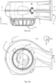
Fig. 1 shows a front view on an embodiment of a pump housing of a centrifugal pump according to the present disclosure; -
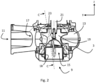
Fig. 2 shows a longitudinal sectional view on the embodiment as shown inFig. 1 ; -
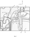
Fig. 3 shows a detail sectional view on plane C-C as outlined inFig. 2 ; -
Fig. 4 shows a more detailed sectional view showing the interaction of an impeller vane with a scraper according to the present disclosure; -
Fig. 5 shows a perspective view on an impeller of the embodiment of a centrifugal pump according to the present disclosure; -
Fig. 6 shows a front view on the impeller shown inFig. 5 ; -
Figs. 7a,b show a sectional front view and a rear view, respectively, on a suction inlet with scraper of the embodiment of a centrifugal pump according to the present disclosure; -
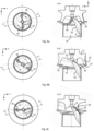
Figs. 8a-c show the interaction of an impeller vane with a scraper according to the present disclosure in different angular positions of the impeller during rotation, wherein the figure on the left is a bottom view and the figure on the right is a corresponding sectional view on plane H-H as outlined in the figure on the left; -
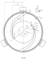
Fig. 9 shows a top view on the cover surface of the embodiment of a centrifugal pump according to the present disclosure; -
Fig. 10 shows a top view on an alternative embodiment of a cover surface of a suction inlet of a centrifugal pump according to the present disclosure; -
Figs. 11a,b show a rear view on the pump housing and a cross-sectional view on plane B-B as outlined inFig. 11a with the cover surface as shown inFig. 10 ; -
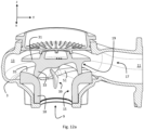
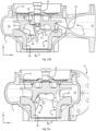
Fig. 12a-c show different sectional partial views on another embodiment of a centrifugal pump according to the present disclosure; -
Figs. 13a,b show different views of an impeller of a centrifugal pump according to the embodiment shown inFigs. 12a-c ; -
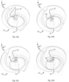
Figs. 14a-d show perspective views of the impeller shown inFigs. 13a ,b in different rotational positions relative to the scraper; -
Fig. 15a-c show different views of a suction inlet including a cover surface of a centrifugal pump according to the embodiment shown inFigs. 12a-c ; and -
Figs. 16a-c show the interaction of an impeller vane with a scraper according to the embodiment shown inFigs. 12a-c in different angular positions of the impeller during rotation, wherein the figure on the left is a bottom view and the figure on the right is a corresponding sectional view on plane E-E as outline in the figure on the left. -
Fig. 1 shows an elongate centrifugal pump 1 as a submersible wastewater pump that can be submersed into a wastewater pit or a duct to pump wastewater with fibrous substances. The pump 1 comprises apump housing 3, amotor housing 5 and anelectronics housing 7 arranged essentially along a vertical rotor axis R, wherein themotor housing 5 is arranged between thepump housing 3 and theelectronics housing 7. The pump housing defines afluid inlet 9 and afluid outlet 11. Thefluid inlet 9 is here a bottom opening in thepump housing 3, wherein the bottom opening is coaxial with the rotor axis R. - It should be noted that the vertical pump setup shown herein is only a preferred setup. The rotor axis R may extend vertically or horizontally or in any other direction. For the sake of convenience, a right-handed Cartesian coordinate system is given in each figure, wherein the z-axis extends along the rotor axis R, i.e. here vertically upwards, the y-axis extends sideways out of the
fluid outlet 11, and the x-axis extends forward. The terms "top", "bottom", "front" and "rear" thus refer to respective directions along the z-axis or x-axis. The direction of impeller rotation is here counter-clockwise about the rotor axis R when seen from the bottom upwards in z-direction. -
Fig. 2 shows that thepump housing 3 encloses apump chamber 13 comprising asuction inlet 15 and apressure outlet 17, wherein thesuction inlet 15 comprises here aninlet sleeve 18 being coaxially arranged with the rotor axis R and extending from thefluid inlet 9 to thepump chamber 13. Thepressure outlet 17 of thepump chamber 13 is arranged radially outward in lateral y-direction. Animpeller 19 is rotatably arranged within thepump chamber 13 for being driven to rotate about the rotor axis R.A rotor axle 21 is fixed to acentral hub 23 of theimpeller 19 and extends upwards in z-direction along the rotor axis R out of thepump housing 3 into themotor housing 5, which is attached to the top of thepump housing 3. -
Fig. 3 shows thepump chamber 13 in more detail when seen essentially in negative y-direction from thefluid outlet 11. Theimpeller 19 comprises anupper impeller base 31 from which twoimpeller vanes 33 extend downward towards thesuction inlet 15. Thesuction inlet 15 widens towards theimpeller 19 by means of a slightly convexly shapedcover surface 35 arranged at the upper end of theinlet sleeve 18. Each of theimpeller vanes 33 comprises avane ridge surface 37 facing thecover surface 35 with a cover gap h of 0.1 to 1 mm, e.g. approximately 1 mm, between them (seeFig. 4 ). The vane ridge surfaces 37 slide along thecover surface 35 upon rotation of theimpeller 19. Ascraper 39 in form of a finger projects essentially upward into a central dome-shaped volume 41 (seeFig. 5 ) described by impeller rotation and which is not crossed by theimpeller vanes 33 during impeller rotation. The central dome-shapedvolume 41 has the largest radius of essentially the inner radius of theinlet sleeve 18 at thesuction inlet 15 and the smallest radius of essentially the radius of thecentral hub 23 at theimpeller base 31. Thescraper 39 is fixed to theinlet sleeve 18 and projects upwards towards thecentral hub 23 into the dome-shapedvolume 41. -
Fig. 4 shows the interaction of thescraper 39 and theimpeller 19 in more detail. Thescraper 39 comprises a machined radially outwardscraper surface 43 acting as afirst scraping path 43 and being positioned to form a scrape gap g (best visible inFig. 8c on the right) of 0.1 to 5 mm, e.g. in the range of 0.3 to 2mm or of approximately 1 mm, to a machined radiallyinnermost vane surface 45 acting as asecond scraping path 45. Upon impeller rotation, thesecond scraping path 45 of theimpeller vanes 33 slides along thefirst scraping path 43 of thestationary scraper 39, whereby fibrous substances are scraped off thesecond scraping path 45. It is thesecond scraping path 45 of theimpeller vanes 33 that describes the dome-shapedcentral volume 41 during impeller rotation. - When the impeller rotates, fibrous substances are not cut by the scraper, but rather scraped pushed away by the
scraper 39 and by the interaction between the guidingsurface 47 of thescraper 39 facing essentially backwardly in circumferential direction of impeller rotation, i.e. here in positive y-direction and the rotating impeller vanes. The guidingsurface 47 of thescraper 39, and in this embodiment thescraper 39 as a whole, is inclined backwardly by up to 30 ° in circumferential direction of impeller rotation, i.e. here in positive y-direction, from theinlet sleeve 18 to ascraper end 49 close to thecentral hub 23 of theimpeller base 31. Except for thefirst scraping path 43 of thescraper 19, the surfaces of thescraper 39 in general are smoothly curved to reduce the fluidic resistance. - The
scraper 19 guides fibrous substances towards thecover surface 35, which comprisesgrooves 51 along which fibrous substances can be transported radially outward. Eachgroove 51 extends from agroove inlet port 53 at an inner radius r1 of thecover surface 35 to agroove outlet port 55 at an outer radius r2 of the cover surface 35 (best visible inFigs. 9 and10 ). Thescraper 39 is located relative to thegrooves 51 such that the guidingsurface 47 is not far behind agroove inlet port 53 of agroove 51, i.e. at an angular distance of less than 90° forward in circumferential direction of impeller rotation, so that the fibrous substances agglomerated at the guidingsurface 47 can easily enter thegroove 51. This is illustrated infigures 3 ,9 , and10 . -
Figs. 5 and6 show the specific design of theimpeller 19 in more detail. Theupper impeller base 31 is essentially a base plate comprising thecentral hub 23 for fixing therotor axle 21. The twoimpeller vanes 33 extend essentially axially downward from theimpeller base 31, wherein theimpeller base 31 and theimpeller vanes 33 are formed as an integrally mouldedimpeller 19. Alternatively, theimpeller 19 may comprise one or more than two vanes. In case of two or more vanes, the twoimpeller vanes 33 are arranged with respect to each other in a rotational symmetry. They are curved in form of a spiral section in the xy-plane perpendicular to the rotor axis R. - The essentially downwardly facing vane ridge surfaces 37 of the
impeller vanes 33 are machined in this example and do not extend to thecentral hub 23 of theimpeller base 31. Eachvane ridge surface 37 has a circumferentially forward end at aleading edge 57 of theimpeller vane 33 and a circumferentially backward end at a trailingedge 59 of theimpeller vane 33. The leadingedge 57 of eachimpeller vane 33 may be defined as the path of circumferentially most forward vane surface points, i.e. where theimpeller vane 33 hits the pumped fluid first. The trailingedge 57 of eachimpeller vane 33 may be defined as the path of circumferentially most backward vane surface points, i.e. where the fluid separates from theimpeller vane 33 towards the radiallyoutward pressure outlet 17. - The leading
edge 57 extends from a leadingedge base point 61 at theimpeller base 31 to a leadingedge ridge point 63 at thevane ridge surface 37, wherein the leadingedge 57 is backwardly swept from the leadingedge base point 61 to the leadingedge ridge point 63. The backward sweep is best seen inFig. 6 . The backward sweep at a point of the leading edge means that a tangent plane at that point is inclined "backward" in circumferential direction of rotation with respect to a plane extending along the rotor axis R and through that point. The backward sweep transports fibrous substances towards the leadingedge ridge point 63, where it can be effectively pushed and scraped off by thescraper 39. The leadingedge 57 is swept backwardly by a leading edge sweep angle α1 of at least 20° at the leadingedge ridge point 63. The leadingedge 57 comprises a lowerfirst section 65 and an uppersecond section 67. Thefirst section 65 extends from the leadingedge ridge point 63 upward to the uppersecond section 67, which ends at the leadingedge base point 61. The leading edge sweep angle is larger in thesecond section 67 than in thefirst section 65. In particular, the leading edge sweep angle α2 at the leadingedge base point 61 is larger than the leading edge sweep angle α1 of at least 20° at the leadingedge ridge point 63, e.g. α2 ≈ 90°, i.e. there may be effectively no sweep at the leadingedge base point 61. - The preferably machined radially innermost vane surface acting as a
second scraping path 45 is hatched inFig. 5 . It extends from thecentral hub 23 to the leadingedge ridge point 63. In circumferential forward direction, thesecond scraping path 45 extends to thefirst section 65 of the leadingedge 57. Thesecond section 67 of the leadingedge 57 departs radially outward from thesecond scraping path 45. Upon impeller rotation, thesecond scraping path 45 of theimpeller vanes 33 describes the dome-shapedcentral volume 41 into which thescraper 39 can protrude. The dome-shapedcentral volume 41 is visualised by dashed paths inFigs. 5 and6 . The dome-shapedcentral volume 41 is wider towards thesuction inlet 15, i.e. downwards, than towards theimpeller base 31, i.e. upwards. The bottom radius of the dome-shapedcentral volume 41 is approximately equal to the inner radius of theinlet sleeve 18, whereas the top radius of the dome-shapedcentral volume 41 is approximately equal to the inner radius ofcentral hub 23. The depth of thecentral volume 41 in axial direction in denoted as Hcv inFig. 6 . - The
vane ridge surface 37 of eachimpeller vane 33 is backwardly swept by a sweep angle β of more than 90° at the leadingedge ridge point 63, so that the height of theimpeller vanes 33 reduces from the leadingedge ridge point 63 towards the trailingedge 59. In other words, a normal vector of thevane ridge surface 37 has a vector component directed backwardly against circumferential direction of impeller rotation. - The impeller vanes 33 are radially outwardly tilted from the
impeller base 31 to thevane ridge surface 37 by a tilt angle γ of up to 60°, preferably up to 20°. -
Figs. 7a,b show thescraper 39 in more detail. Thescraper 39 is smoothly curved backward from theinlet sleeve 18 towards theupper scraper end 49. The radiallyoutward scraper surface 43 acting as afirst scraping path 43 is hatched inFig. 7b . The scraper is long enough to scrape off fibres from thecentral volume 41. The height of thescraper 39 in axial direction in denoted as Hs inFigs. 7a ,b. The height Hs is more than 50% of the depth Hcv of thecentral volume 41 in axial direction as shown in inFig. 6 . -
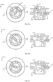
Figs. 8a-c show on the left bottom views through theinlet sleeve 18 on theimpeller 19 at different angular positions during impeller rotation. InFig. 8a , thesecond scraping path 45 of one of theimpeller vanes 33 starts interacting with thestationary scraper 39. InFig. 8b , theimpeller 19 is rotated further by about 45° so that thesecond scraping path 45 is in the process of passing by thescraper 39. InFig. 8c , theimpeller 19 is rotated further by about another 45° so that thesecond scraping path 45 has just fully passed thefirst scraping path 43 of thescraper 39. The sectional view on plane H-H on the right ofFig. 8c shows that thesecond scraping path 45 and thefirst scraping path 43 of thescraper 39 are essentially parallel for a moment with the scrape gap g between them. The scrape gap g is essentially constant along thescraper 39 or increases slightly towards theimpeller base 31. - In
Fig. 8a on the right, a scraper connection angle φ in the range of 110° to 170° is displayed. Thescraper 39 comprises ascraper ridge 52 which the upward flowing fluid hits first, i.e. it acts as a static scraper leading edge. Thescraper ridge 52 is a path on a rounded scraper surface from theinlet sleeve 18 to thescraper end 49, whereby the fluidic resistance of the scraper is reduced. In order to prevent fibrous substances from getting entangled at thescraper ridge 52, thescraper ridge 52 is swept in the direction of fluid flow by the scraper sweep angle, which is mostly larger than the scraper connection angle φ and mostly increases towards thescraper end 49. The scraper connection angle φ may be defined by the obtuse angle between a tangent at the radially outermost point of the scraper ridge and an axis parallel to the rotor axis through that point. The scraper sweep angle may be analogously defined for any point along the scraper ridge. -
Fig. 9 shows a top view on thecover surface 35 with threegrooves 51 that may be identical and arranged in a three-fold rotational symmetry, i.e. at an angular distance of 120° to each other. Eachgroove 51 extends from agroove inlet port 53 at an inner radius r1 of thecover surface 35 at a first angular position ϕ1 to agroove outlet port 55 at an outer radius r2 of thecover surface 35 at a second angular position ϕ2. The second angular position ϕ2 is further forward in the direction of impeller rotation. A radially innerfirst section 69 of thegrooves 51, is curved in form of a spiral section with a relatively slow radial growth of
second section 71 of thegrooves 51, is curved in form of a spiral section with a relatively fast radial growth of
grooves 51 between thefirst section 69 and thesecond section 71. This is advantageous to reduce the time needed for fibrous substances to travel along thegrooves 51. - The position of the
scraper 39 relative to thegrooves 51 is indicated by dashed lines inFigs. 9 and10 . The guidingsurface 47 of thescraper 39 is not far behind one of the agroove inlet ports 53, i.e. at an angular distance θ1 of less than 90° forward in circumferential direction of impeller rotation, so that the fibrous substances agglomerated at the guidingsurface 47 can easily enter thegroove 51. The angular size θ2 of thegroove inlet ports 53 extending from a firstangular end 72 to a secondangular end 74 is less than 90 °. The guidingsurface 47 of thescraper 39 may have a distance θ1 - θ2 to thesecond end 74, which is located behind the firstangular end 72 in circumferential direction of impeller rotation. Preferably, the distance θ1 - θ2 is small (seeFig. 10 ) or zero (seeFig. 15b ). -
Fig. 10 shows a top view on an alternative embodiment of thecover surface 35 with two essentiallyidentical grooves 51 arranged in a two-fold rotational symmetry, i.e. at an angular distance of 180° to each other. Thegrooves 51 follow one long spiral path from thegroove inlet port 53 to thegroove outlet port 55 with an average radial growth of
grooves 51 increases from thegroove inlet port 53 towards thegroove outlet port 55. - As shown in
Figs. 11a,b , thegrooves 51 are arranged in a certain position relative to thepressure outlet 17, so that thegroove outlet ports 55 have an angular position φ2 in the range 20° ≤ φ2 ≤ 310°, wherein an angular position of φ2 = 0° corresponds to the angular position of thepressure outlet 17. The fibrous substances then follow a path as indicated inFig. 11b by a dashed arrow from thegroove outlet port 55 to thepressure outlet 17. -
Figs. 12a-c show another embodiment of the centrifugal pump 1, which have the most aspects and features in common with the previously described embodiment, but differs in some aspects and features. Firstly, in contrast to the previously described embodiment, thesuction inlet 15 is here formed as an integral part by thesuction sleeve 18, the suction cover including thesuction cover surface 35 and thegroove 51 and thescraper 39. Such an integral design may reduce the diversity of parts as well as the construction and assembly complexity. In this embodiment, the scrape gap g and the cover gap h may not be individually adjustable, but only together or not at all. Secondly, the embodiment differs from the previously described embodiment in that the suction cover only comprises onesingle groove 51, which is wider and deeper than the previously describedgrooves 51. As can be seen in more detail inFigs. 15a-c , the relatively largegroove inlet port 53 is located directly at thescraper 39. Also, the angular position of thescraper 39 within thepump housing 3 is rotated by 180°. Finally, the shape of theimpeller vanes 33 differs in some aspects. For instance, the radiallyinnermost vane path 45 is not part of a machined surface, but a path on a smoothly curved non-machined radially inner vane surface (seeFigs. 13a -c). This has the advantage that the risk of cavitation effects is reduced by a fluid-dynamically optimised vane shape with less machined sharp edges. Also thefirst scraping path 43 on thescraper 39 may be a path on a non-machined surface rather than a machined first scraping surface. - As can be seen in
Figs. 13a,b , the leadingedge 57 has here no surface points in common with the radiallyinnermost vane path 45. This means that the leading edge has a distance in radial and circumferential direction from the radiallyinnermost vane path 45. This is fluid-dynamically beneficial and still effective to scrape off fibres, because tests have shown that thescraper 39 is physically most effective to transport fibres from theimpeller base 31 towards thevane ridge 37. Once the fibres have reached a certain distance from theimpeller base 31, the fibres automatically find their way towards thegroove inlet port 53. It is further advantageous that the distance in radial and/or circumferential direction between theleading edge 57 and the radiallyinnermost vane path 45 increases towards theimpeller base 31. In other words, the distance decreases away from theimpeller base 31, which facilitates guiding the fibres into thegroove inlet port 53. - As can be seen in
Figs. 13a ,b , the radiallyinnermost vane path 45 comprises afirst section 75 having a convex shape and asecond section 77 having a concave shape. Thesecond section 77 is closer to theimpeller base 31 than thefirst section 75. This results in a bell-shapedcentral volume 41 as the virtual surface of revolution defined by rotation of the radiallyinnermost vane path 45. Consequently, a longitudinal cut of thecentral volume 41 is concave where the radiallyinnermost vane path 45 is convex and vice versa. Such as bell-shape of thecentral volume 41 has shown to perform very well for transporting off fibres into thegroove inlet port 53. - Similar to the embodiment shown in
Figs. 6 and7 , the height Hs of the at least onescraper 39 in axial direction is at least 50% of the depth Hcv of thecentral volume 41 in axial direction (seeFigs. 13b and15c ). This is beneficial to guide fibres that are located close to theimpeller base 31 towards thegroove inlet port 53. -
Figs. 14a-d illustrate in different angular positions of theimpeller 19 relative to thescraper 39 the distance in radial and/or circumferential direction between theleading edge 57 and the radiallyinnermost vane path 45. So, the leadingedge 57 and the radiallyinnermost vane path 45 are completely separate surface paths. -
Figs. 15a-c show theintegral suction inlet 15, preferably as an integrally moulded part, in more detail. The relatively largegroove inlet port 53 has an angular size of 45° < θ2 < 90°. As the guidingsurface 47 of thescraper 39 is directly located at the secondangular end 74 of thegroove inlet port 53, the angular distance θ1 - θ2 is zero. - Analogous to
Figs. 8a-c ,Figs. 16a-c show the functioning of the embodiment according toFigs. 12a-c in different angular positions of theimpeller 19.Figs. 16a-c show on the left bottom views through theinlet sleeve 18 on theimpeller 19 at different angular positions during impeller rotation (counter-clockwise inFigs. 16a-c on the left). InFig. 16a , thesecond scraping path 45 of one of theimpeller vanes 33 is positioned about 90° before thestationary scraper 39. InFig. 16b , theimpeller 19 is rotated further by about 45° so that thesecond scraping path 45 is closer to passing by thescraper 39. InFig. 16c , theimpeller 19 is rotated further by about another 45° so that thesecond scraping path 45 is in the process of passing thefirst scraping path 43 of thescraper 39. The sectional view on plane E-E on the right ofFig. 16c shows that thefirst scraping path 43 of thescraper 39 scrapes off fibres from thesecond section 77 of thesecond scraping path 45 before it scrapes off fibres from thefirst section 75 of thesecond scraping path 45. This achieved by the inclination of thescraper 39 against the rotation direction (seeFig. 15c ) and facilitates the fibre transport towards thegroove inlet port 53. The scrape gap g, however, is essentially constantly about 1mm along thescraper 39. - In
Fig. 16a on the right, the scraper connection angle φ in the range of 110° to 170° is displayed. Thescraper 39 comprises ascraper ridge 52 which the upward flowing fluid hits first, i.e. it acts as a static scraper leading edge. Thescraper ridge 52 is a path on a rounded scraper surface from theinlet sleeve 18 to thescraper end 49, whereby the fluidic resistance of the scraper is reduced. In order to prevent fibrous substances from getting entangled at thescraper ridge 52, thescraper ridge 52 is swept in the direction of fluid flow by the scraper sweep angle, which is mostly larger than the scraper connection angle φ and mostly increases towards thescraper end 49. The scraper connection angle φ may be defined by the obtuse angle between a tangent at the radially outermost point of the scraper ridge and an axis parallel to the rotor axis through that point. The scraper sweep angle may be analogously defined for any point along the scraper ridge. - Where, in the foregoing description, integers or elements are mentioned which have known, obvious or foreseeable equivalents, then such equivalents are herein incorporated as if individually set forth. Reference should be made to the claims for determining the true scope of the present disclosure, which should be construed so as to encompass any such equivalents. It will also be appreciated by the reader that integers or features of the disclosure that are described as optional, preferable, advantageous, convenient or the like are optional and do not limit the scope of the independent claims.
- The above embodiments are to be understood as illustrative examples of the disclosure. It is to be understood that any feature described in relation to any one embodiment may be used alone, or in combination with other features described, and may also be used in combination with one or more features of any other of the embodiments, or any combination of any other of the embodiments. While at least one exemplary embodiment has been shown and described, it should be understood that other modifications, substitutions and alternatives are apparent to one of ordinary skill in the art and may be changed without departing from the scope of the subject matter described herein, and this application is intended to cover any adaptations or variations of the specific embodiments discussed herein.
- In addition, "comprising" does not exclude other elements or steps, and "a" or "one" does not exclude a plural number. Furthermore, characteristics or steps which have been described with reference to one of the above exemplary embodiments may also be used in combination with other characteristics or steps of other exemplary embodiments described above. Method steps may be applied in any order or in parallel or may constitute a part or a more detailed version of another method step. It should be understood that there should be embodied within the scope of the patent warranted hereon all such modifications as reasonably and properly come within the scope of the contribution to the art. Such modifications, substitutions and alternatives can be made without departing from the spirit and scope of the disclosure, which should be determined from the appended claims and their legal equivalents.
-
- 1
- pump
- 3
- pump housing
- 5
- motor housing
- 7
- electronics housing
- 9
- fluid inlet
- 11
- fluid outlet
- 13
- pump chamber
- 15
- suction inlet
- 17
- pressure outlet
- 18
- inlet sleeve
- 19
- impeller
- 21
- rotor axle
- 23
- central hub
- 31
- impeller base
- 33
- impeller vanes
- 35
- cover surface
- 37
- vane ridge surface
- 39
- scraper
- 41
- central volume
- 43
- first scraping path of scraper
- 45
- second scraping path of impeller vanes
- 47
- guiding surface
- 49
- scraper end
- 51
- groove(s)
- 52
- scraper ridge
- 53
- groove inlet port
- 55
- groove outlet port
- 57
- leading edge
- 59
- trailing edge
- 61
- leading edge base point
- 63
- leading edge ridge point
- 65
- first section of leading edge
- 67
- second section of leading edge
- 69
- first section of the groove(s)
- 71
- second section of the groove(s)
- 72
- first angular end of groove inlet port
- 73
- knee of the groove(s)
- 74
- second angular end of groove inlet port
- 75
- first section of second scraping path
- 77
- second section of second scraper path
- g
- scrape gap
- h
- cover gap
- α
- leading edge sweep angle
- α1
- leading edge sweep angle at leading edge ridge point
- α2
- leading edge sweep angle at leading edge base point
- β
- sweep angle of vane ridge surface
- γ
- tilt angle of impeller vanes
- φ
- scraper connection angle
- r1
- inner radius of cover surface
- r2
- outer radius of cover surface
- ϕ1
- first angular position of groove inlet port(s)
- ϕ2
- second angular position of groove outlet port(s)
- θ1
- angular distance between guiding surface and groove inlet port
- θ2
- angular size of groove inlet port
- Hs
- height of the scraper in axial direction
- Hcv
- depth of the central volume in axial direction
Claims (6)
- An impeller (19) for being installed in a centrifugal pump,
wherein the impeller (19) comprises an impeller base (31) and one or more vanes (33) extending from the impeller base (31), wherein each of the impeller vanes (33) comprises a radially innermost vane path (45) describing during impeller rotation a central volume (41) that widens away from the impeller base (31), wherein each of the impeller vanes (33) comprises a leading edge (57) extending from a leading edge base point (61) at the impeller base (31) to a leading edge ridge point (63) at a vane ridge surface (37), wherein the leading edge (57) is backwardly swept from the leading edge base point (61) to the leading edge ridge point (63), wherein the leading edge (57) has a distance in radial and/or circumferential direction from the radially innermost vane path (45). - The impeller (19) according to claim 1, wherein the leading edge (57) is swept backwardly by a leading edge sweep angle (α1) of at least 20° at the leading edge ridge point (63).
- The impeller (19) according to claim 1 or 2, wherein the leading edge sweep angle (α2) is larger at the leading edge base point (61) than at the leading edge ridge point (63), wherein the leading edge sweep angle (α) is least 20° between the leading edge base point (61) and the leading edge ridge point (63).
- The impeller (19) according to any of the preceding claims, wherein the distance in radial and/or circumferential direction between the leading edge (57) and the radially innermost vane path (45) increases towards the impeller base (51).
- The impeller (19) according to any of the preceding claims, wherein each of the impeller vanes (33) is radially outwardly tilted from the impeller base (31) to a vane ridge surface (37) by a tilt angle (γ) of up to 60°, preferably up to 20°.
- The impeller (19) according to any of the preceding claims, wherein the radially innermost vane path (45) comprises a first section (75) having a convex shape and a second section (77) having a concave shape.
Applications Claiming Priority (3)
| Application Number | Priority Date | Filing Date | Title |
|---|---|---|---|
| EP18215565 | 2018-12-21 | ||
| EP19827725.3A EP3899285B1 (en) | 2018-12-21 | 2019-12-19 | Centrifugal pump with scraper |
| PCT/EP2019/086375 WO2020127782A1 (en) | 2018-12-21 | 2019-12-19 | Centrifugal pump with scraper |
Related Parent Applications (1)
| Application Number | Title | Priority Date | Filing Date |
|---|---|---|---|
| EP19827725.3A Division EP3899285B1 (en) | 2018-12-21 | 2019-12-19 | Centrifugal pump with scraper |
Publications (2)
| Publication Number | Publication Date |
|---|---|
| EP4397866A2 true EP4397866A2 (en) | 2024-07-10 |
| EP4397866A3 EP4397866A3 (en) | 2024-09-04 |
Family
ID=64901882
Family Applications (3)
| Application Number | Title | Priority Date | Filing Date |
|---|---|---|---|
| EP19827725.3A Active EP3899285B1 (en) | 2018-12-21 | 2019-12-19 | Centrifugal pump with scraper |
| EP24176536.1A Active EP4394188B1 (en) | 2018-12-21 | 2019-12-19 | Centrifugal pump |
| EP24176535.3A Withdrawn EP4397866A3 (en) | 2018-12-21 | 2019-12-19 | Impeller for a centrifugal pump |
Family Applications Before (2)
| Application Number | Title | Priority Date | Filing Date |
|---|---|---|---|
| EP19827725.3A Active EP3899285B1 (en) | 2018-12-21 | 2019-12-19 | Centrifugal pump with scraper |
| EP24176536.1A Active EP4394188B1 (en) | 2018-12-21 | 2019-12-19 | Centrifugal pump |
Country Status (4)
| Country | Link |
|---|---|
| US (1) | US11603844B2 (en) |
| EP (3) | EP3899285B1 (en) |
| CN (1) | CN113195901B (en) |
| WO (1) | WO2020127782A1 (en) |
Families Citing this family (5)
| Publication number | Priority date | Publication date | Assignee | Title |
|---|---|---|---|---|
| EP3988793B1 (en) * | 2020-10-26 | 2024-08-07 | Xylem Europe GmbH | Pump comprising an impeller seat with a guide pin |
| EP3988795B1 (en) | 2020-10-26 | 2024-07-31 | Xylem Europe GmbH | Impeller seat with a guide pin and a feeding groove for a pump |
| EP3988794B1 (en) * | 2020-10-26 | 2024-07-31 | Xylem Europe GmbH | Impeller seat with a guide pin for a pump |
| US20260036132A1 (en) | 2021-10-04 | 2026-02-05 | KSB SE & Co. KGaA | Centrifugal Pump Having Wear-Resistant Wear Plate With Scraper Element |
| DE102022124356A1 (en) | 2021-10-04 | 2023-05-25 | KSB SE & Co. KGaA | Centrifugal pump with wear-resistant wear plate with scraper element wear-resistant wear plate with scraper element |
Citations (1)
| Publication number | Priority date | Publication date | Assignee | Title |
|---|---|---|---|---|
| EP1357294A2 (en) | 2002-04-26 | 2003-10-29 | Itt Manufacturing Enterprises, Inc. | Sewage pump |
Family Cites Families (17)
| Publication number | Priority date | Publication date | Assignee | Title |
|---|---|---|---|---|
| GB812371A (en) | 1955-03-23 | 1959-04-22 | Parkinson Cowan Appliances Ltd | Improvements relating to centrifugal pumps |
| DE240859C (en) | 1911-04-14 | 1911-11-18 | CENTRIFUGAL PUMP FOR CONVEYED LOAD WITH SOLID COMPONENTS | |
| US1754992A (en) * | 1926-12-06 | 1930-04-15 | American Well Works | Centrifugal pump |
| US3096718A (en) * | 1961-12-12 | 1963-07-09 | Conard Kenner | Trash cutter for a pump |
| US3447475A (en) * | 1967-01-09 | 1969-06-03 | Albert Blum | Centrifugal pump |
| JPS5136721Y2 (en) | 1973-09-06 | 1976-09-09 | ||
| JPS5357507A (en) * | 1976-11-04 | 1978-05-24 | Kubota Ltd | Cutter underwater pumps |
| US4896445A (en) * | 1980-12-30 | 1990-01-30 | Deal Troy M | Method for reducing costs and environmental impact of dredging |
| US6832887B2 (en) * | 2002-04-09 | 2004-12-21 | K-Tron Technologies, Inc. | Bulk material pump feeder |
| SE527818C2 (en) | 2005-06-17 | 2006-06-13 | Itt Mfg Enterprises Inc | Pump is for moving contaminated fluid including solid material and has pump housing, rotatable pump wheel with at least one blade and pump wheel seat containing at least one recess in its upper surface |
| SE527964C2 (en) | 2005-07-01 | 2006-07-25 | Itt Mfg Enterprises Inc | Pump for pumping contaminated liquid including solids |
| US8025479B2 (en) * | 2006-03-28 | 2011-09-27 | The Gorman-Rupp Company | Impeller |
| CN104685217B (en) * | 2012-08-23 | 2017-10-24 | 苏尔寿管理有限公司 | Pumps for conveying waste water and impellers and base plates for such pumps |
| WO2014073140A1 (en) * | 2012-11-08 | 2014-05-15 | 新明和工業株式会社 | Centrifugal pump |
| DE102012023734A1 (en) * | 2012-12-05 | 2014-06-05 | Wilo Se | Centrifugal pump especially for sewage or dirty water |
| JP6488167B2 (en) * | 2015-03-27 | 2019-03-20 | 株式会社荏原製作所 | Centrifugal pump |
| FR3078116B1 (en) * | 2018-02-22 | 2021-09-10 | Ksb Sas | FINGER PUMP |
-
2019
- 2019-12-19 EP EP19827725.3A patent/EP3899285B1/en active Active
- 2019-12-19 EP EP24176536.1A patent/EP4394188B1/en active Active
- 2019-12-19 CN CN201980085128.3A patent/CN113195901B/en active Active
- 2019-12-19 US US17/415,351 patent/US11603844B2/en active Active
- 2019-12-19 WO PCT/EP2019/086375 patent/WO2020127782A1/en not_active Ceased
- 2019-12-19 EP EP24176535.3A patent/EP4397866A3/en not_active Withdrawn
Patent Citations (2)
| Publication number | Priority date | Publication date | Assignee | Title |
|---|---|---|---|---|
| EP1357294A2 (en) | 2002-04-26 | 2003-10-29 | Itt Manufacturing Enterprises, Inc. | Sewage pump |
| EP1357294B1 (en) | 2002-04-26 | 2018-07-04 | Xylem IP Holdings LLC | Sewage pump |
Also Published As
| Publication number | Publication date |
|---|---|
| EP4394188A2 (en) | 2024-07-03 |
| US20220056911A1 (en) | 2022-02-24 |
| CN113195901B (en) | 2023-08-15 |
| WO2020127782A1 (en) | 2020-06-25 |
| EP3899285C0 (en) | 2024-05-22 |
| EP3899285B1 (en) | 2024-05-22 |
| CN113195901A (en) | 2021-07-30 |
| EP4397866A3 (en) | 2024-09-04 |
| EP4394188B1 (en) | 2026-07-29 |
| EP4394188A3 (en) | 2024-09-11 |
| EP3899285A1 (en) | 2021-10-27 |
| US11603844B2 (en) | 2023-03-14 |
Similar Documents
| Publication | Publication Date | Title |
|---|---|---|
| EP4394188A2 (en) | Centrifugal pump | |
| EP1284368B1 (en) | Diverter for reducing wear in a slurry pump | |
| CN101198793B (en) | pumping machine | |
| JP2010236555A (en) | Improved pump impeller | |
| SE520416C2 (en) | Impeller | |
| CN109257934B (en) | Rotating part for a thick matter pump | |
| RU2705785C2 (en) | Free-vortex pump | |
| US7510368B2 (en) | Screw-centrifugal pump | |
| US20040136825A1 (en) | Multiple diverter for reducing wear in a slurry pump | |
| EP3276178B1 (en) | Volute pump | |
| WO2023002733A1 (en) | Pump casing and pump | |
| KR100412326B1 (en) | Pulp screening device | |
| CA3045062A1 (en) | Vortex pump | |
| KR101836455B1 (en) | a impeller for pump | |
| JP5300508B2 (en) | Pump impeller and pump | |
| KR102752663B1 (en) | Axial flow pump having a function for cutting foreign substances | |
| EP2233749A1 (en) | Pressurizing centrifugal pump | |
| EP3874169B1 (en) | Eddy pump | |
| JPH0730751B2 (en) | pump | |
| JP2010523867A (en) | Air diffuser system for industrial pumps | |
| KR102774398B1 (en) | High-efficiency centrifugal pump with tongue guide vane | |
| US12320364B2 (en) | Pump for conveying wastewater and impeller for such a pump | |
| EA038891B1 (en) | Inverted annular side gap arrangement for a centrifugal pump | |
| CN119630886A (en) | Foam pump assemblies and parts | |
| HK1124103A (en) | Centrifugal pump |
Legal Events
| Date | Code | Title | Description |
|---|---|---|---|
| PUAI | Public reference made under article 153(3) epc to a published international application that has entered the european phase |
Free format text: ORIGINAL CODE: 0009012 |
|
| STAA | Information on the status of an ep patent application or granted ep patent |
Free format text: STATUS: THE APPLICATION HAS BEEN PUBLISHED |
|
| AC | Divisional application: reference to earlier application |
Ref document number: 3899285 Country of ref document: EP Kind code of ref document: P |
|
| AK | Designated contracting states |
Kind code of ref document: A2 Designated state(s): AL AT BE BG CH CY CZ DE DK EE ES FI FR GB GR HR HU IE IS IT LI LT LU LV MC MK MT NL NO PL PT RO RS SE SI SK SM TR |
|
| REG | Reference to a national code |
Ref country code: DE Ref legal event code: R079 Free format text: PREVIOUS MAIN CLASS: F04D0029220000 Ipc: F04D0029420000 |
|
| PUAL | Search report despatched |
Free format text: ORIGINAL CODE: 0009013 |
|
| AK | Designated contracting states |
Kind code of ref document: A3 Designated state(s): AL AT BE BG CH CY CZ DE DK EE ES FI FR GB GR HR HU IE IS IT LI LT LU LV MC MK MT NL NO PL PT RO RS SE SI SK SM TR |
|
| RIC1 | Information provided on ipc code assigned before grant |
Ipc: F04D 29/24 20060101ALI20240729BHEP Ipc: F04D 29/22 20060101ALI20240729BHEP Ipc: F04D 7/04 20060101ALI20240729BHEP Ipc: F04D 29/42 20060101AFI20240729BHEP |
|
| STAA | Information on the status of an ep patent application or granted ep patent |
Free format text: STATUS: THE APPLICATION IS DEEMED TO BE WITHDRAWN |
|
| 18D | Application deemed to be withdrawn |
Effective date: 20250305 |