EP4397842A2 - Bypass valve - Google Patents
Bypass valve Download PDFInfo
- Publication number
- EP4397842A2 EP4397842A2 EP24150788.8A EP24150788A EP4397842A2 EP 4397842 A2 EP4397842 A2 EP 4397842A2 EP 24150788 A EP24150788 A EP 24150788A EP 4397842 A2 EP4397842 A2 EP 4397842A2
- Authority
- EP
- European Patent Office
- Prior art keywords
- valve
- flow
- pump
- oil
- cavity
- Prior art date
- Legal status (The legal status is an assumption and is not a legal conclusion. Google has not performed a legal analysis and makes no representation as to the accuracy of the status listed.)
- Pending
Links
- 239000012530 fluid Substances 0.000 claims abstract description 150
- 238000011144 upstream manufacturing Methods 0.000 claims abstract description 24
- 238000010276 construction Methods 0.000 claims description 6
- 230000001419 dependent effect Effects 0.000 claims 1
- 230000006870 function Effects 0.000 description 5
- 238000010586 diagram Methods 0.000 description 3
- 230000001052 transient effect Effects 0.000 description 3
- 230000006872 improvement Effects 0.000 description 2
- 238000005461 lubrication Methods 0.000 description 2
- 230000007246 mechanism Effects 0.000 description 2
- 238000000034 method Methods 0.000 description 2
- 238000007789 sealing Methods 0.000 description 2
- 230000009286 beneficial effect Effects 0.000 description 1
- 230000008859 change Effects 0.000 description 1
- -1 e.g. Substances 0.000 description 1
- 230000002706 hydrostatic effect Effects 0.000 description 1
- 230000001050 lubricating effect Effects 0.000 description 1
- 238000012986 modification Methods 0.000 description 1
- 230000004048 modification Effects 0.000 description 1
- 230000000630 rising effect Effects 0.000 description 1
- 230000003068 static effect Effects 0.000 description 1
- 230000001960 triggered effect Effects 0.000 description 1
Images



Classifications
-
- F—MECHANICAL ENGINEERING; LIGHTING; HEATING; WEAPONS; BLASTING
- F01—MACHINES OR ENGINES IN GENERAL; ENGINE PLANTS IN GENERAL; STEAM ENGINES
- F01D—NON-POSITIVE DISPLACEMENT MACHINES OR ENGINES, e.g. STEAM TURBINES
- F01D25/00—Component parts, details, or accessories, not provided for in, or of interest apart from, other groups
- F01D25/18—Lubricating arrangements
- F01D25/20—Lubricating arrangements using lubrication pumps
-
- F—MECHANICAL ENGINEERING; LIGHTING; HEATING; WEAPONS; BLASTING
- F01—MACHINES OR ENGINES IN GENERAL; ENGINE PLANTS IN GENERAL; STEAM ENGINES
- F01M—LUBRICATING OF MACHINES OR ENGINES IN GENERAL; LUBRICATING INTERNAL COMBUSTION ENGINES; CRANKCASE VENTILATING
- F01M1/00—Pressure lubrication
- F01M1/02—Pressure lubrication using lubricating pumps
-
- F—MECHANICAL ENGINEERING; LIGHTING; HEATING; WEAPONS; BLASTING
- F01—MACHINES OR ENGINES IN GENERAL; ENGINE PLANTS IN GENERAL; STEAM ENGINES
- F01M—LUBRICATING OF MACHINES OR ENGINES IN GENERAL; LUBRICATING INTERNAL COMBUSTION ENGINES; CRANKCASE VENTILATING
- F01M1/00—Pressure lubrication
- F01M1/16—Controlling lubricant pressure or quantity
-
- F—MECHANICAL ENGINEERING; LIGHTING; HEATING; WEAPONS; BLASTING
- F16—ENGINEERING ELEMENTS AND UNITS; GENERAL MEASURES FOR PRODUCING AND MAINTAINING EFFECTIVE FUNCTIONING OF MACHINES OR INSTALLATIONS; THERMAL INSULATION IN GENERAL
- F16K—VALVES; TAPS; COCKS; ACTUATING-FLOATS; DEVICES FOR VENTING OR AERATING
- F16K11/00—Multiple-way valves, e.g. mixing valves; Pipe fittings incorporating such valves
- F16K11/02—Multiple-way valves, e.g. mixing valves; Pipe fittings incorporating such valves with all movable sealing faces moving as one unit
- F16K11/06—Multiple-way valves, e.g. mixing valves; Pipe fittings incorporating such valves with all movable sealing faces moving as one unit comprising only sliding valves, i.e. sliding closure elements
- F16K11/065—Multiple-way valves, e.g. mixing valves; Pipe fittings incorporating such valves with all movable sealing faces moving as one unit comprising only sliding valves, i.e. sliding closure elements with linearly sliding closure members
- F16K11/07—Multiple-way valves, e.g. mixing valves; Pipe fittings incorporating such valves with all movable sealing faces moving as one unit comprising only sliding valves, i.e. sliding closure elements with linearly sliding closure members with cylindrical slides
-
- F—MECHANICAL ENGINEERING; LIGHTING; HEATING; WEAPONS; BLASTING
- F16—ENGINEERING ELEMENTS AND UNITS; GENERAL MEASURES FOR PRODUCING AND MAINTAINING EFFECTIVE FUNCTIONING OF MACHINES OR INSTALLATIONS; THERMAL INSULATION IN GENERAL
- F16K—VALVES; TAPS; COCKS; ACTUATING-FLOATS; DEVICES FOR VENTING OR AERATING
- F16K31/00—Actuating devices; Operating means; Releasing devices
- F16K31/12—Actuating devices; Operating means; Releasing devices actuated by fluid
- F16K31/122—Actuating devices; Operating means; Releasing devices actuated by fluid the fluid acting on a piston
- F16K31/1221—Actuating devices; Operating means; Releasing devices actuated by fluid the fluid acting on a piston one side of the piston being spring-loaded
-
- F—MECHANICAL ENGINEERING; LIGHTING; HEATING; WEAPONS; BLASTING
- F05—INDEXING SCHEMES RELATING TO ENGINES OR PUMPS IN VARIOUS SUBCLASSES OF CLASSES F01-F04
- F05D—INDEXING SCHEME FOR ASPECTS RELATING TO NON-POSITIVE-DISPLACEMENT MACHINES OR ENGINES, GAS-TURBINES OR JET-PROPULSION PLANTS
- F05D2260/00—Function
- F05D2260/98—Lubrication
Definitions
- the oil system comprises a primary conduit for fluidly communicating in series, the oil tank, the first pump, the valve, the cavity, and the second pump.
- the means for selectively directing the fluid includes: a normally-closed valve disposed, when the fluid system is in use, fluidly between an inlet of the fluid bypass and an inlet of the part of the aircraft, and a normally-open valve disposed in the fluid bypass; and the normally-closed valve is openable by fluid in the fluid circulation circuit acting on an inlet of the normally-closed valve when pressure of the fluid at the inlet of the normally-closed valve exceeds a first predefined pressure threshold; and the normally-open valve is closeable by fluid in the fluid circulation circuit acting on an inlet of the normally-open valve when pressure of the fluid at the inlet of the normally-open valve exceeds a second predefined pressure threshold.
- valve as defined above and described elsewhere herein may also include one or more of the following features, in whole or in part, and in any combination.
- the housing is cylindrical and the body is a piston translatable within the cylindrical housing.
- the flow inlet and the first flow outlet are different sizes, and wherein the flow inlet and the second flow outlet are the same size.
- the size may refer to the cross-sectional area of the respective inlet or outlet.
- the cross-sectional area may be defined in a plane perpendicular to a longitudinal axis of the inlet or outlet.
- an aircraft engine comprising: the valve as defined above and/or elsewhere herein; a compressor section fluidly connected to air to a cavity of the aircraft engine, a pumped oil circulation circuit including an oil tank and the cavity; and a bypass conduit fluidly connecting the first flow outlet of the valve to a location in the oil circulation circuit that is downstream of the cavity; and wherein the flow inlet and the second flow outlet of the valve are part of the oil circulation circuit at a location fluidly upstream of the cavity.
- the reference port is connected to the oil tank at a location in the oil tank that is above a maximum oil level of the oil tank.
- the valve can be configured to provide flow to the second pump in both a first state and a second state of the valve to continuously lubricate the second pump regardless of the state of the valve.
- flow from the oil tank in the first state of the valve, flow from the oil tank is allowed to pass from the valve directly to the second pump and is blocked from passing to the cavity, and in the second state of the valve, flow from the oil tank is allowed to pass from the valve to the cavity and is blocked from passing directly to the second pump.
- the system can include a primary conduit for fluidly communicating in series, the oil tank, the first pump, the valve, the cavity, and the second pump.
- the system can include a bypass conduit for fluidly communicating in series, the valve, and the second pump, bypassing the cavity.
- the valve in the first state of the valve, can be configured to block flow from the first pump from passing though the valve to the cavity via the primary conduit and to allow flow from the first pump to pass through the valve to the second pump via the bypass conduit. In embodiments, in the second state of the valve, the valve can be configured to allow flow from the first pump to pass though the valve to the cavity via the primary conduit and to block flow from the first pump from passing through the valve to the second pump via the bypass conduit.
- the valve can be configured to move between the first state and the second state based on two pressure references.
- a first pressure reference can be a low pressure air flow fluidly connected to a vent of the oil tank and a second pressure reference can be a high pressure air flow fluidly connected to compressor section of the aircraft engine.
- a pressure of the high pressure air flow on a first side of the valve can be less than a pressure of the low pressure air flow and a bias force on a second side of the valve such that the low pressure air maintains the valve in the first state.
- the pressure of the high pressure air flow on the first side of the valve can be greater than the pressure of the low pressure air flow and the bias force on the second side of the valve such that the pressure of the high pressure air flow maintains the valve in the second state.
- a valve in accordance with at least one aspect of this disclosure, there is provided a valve.
- the valve includes a valve housing defining a flow inlet, first flow outlet, a second flow outlet, and a reference port.
- the valve includes a piston within the valve housing configured to move within the housing between a first position fluidly communicating the flow inlet and the first flow outlet and a second position fluidly communicating the flow inlet and the second flow outlet.
- the valve further includes a biasing member inside the housing and axially between connected to the piston and an end of the valve housing, the biasing member biasing the piston to the first position and having a biasing strength selected to be overcome by a predefined pressure acting on the piston and to thereby allow the piston to move toward a position corresponding to the second state as a function of the pressure acting on the piston which actuates the piston between a first position and the second position of the piston.
- valve housing can define a longitudinal axis extending from an opening of the flow inlet to an opening of the reference port, the piston configured to translate axially within the valve housing along the longitudinal axis.
- an opening of the first flow outlet and an opening of the second flow outlet can be oriented orthogonal to the longitudinal axis.
- the flow inlet and the first flow outlet can be different sizes, and the flow inlet and the second flow outlet can be the same size. In certain embodiments, the flow inlet, the first flow outlet, and the second flow outlet can all be same size.
- the valve can be or can include an oil delay valve.
- the fluid system can include a pumped fluid circulation circuit including a fluid tank, the fluid circulation circuit configured to circulate a fluid through at least a part of the aircraft engine, means, in the fluid circulation circuit, for selectively directing a fluid of the fluid circulation circuit as a function of a pressure of fluid in the fluid circulation circuit to one of a part of the aircraft engine, and a fluid bypass in the fluid circulation circuit that is fluidly upstream of the part.
- the means for selectively directing the fluid can include a normally-closed valve disposed, when the fluid system is in use, fluidly between an inlet of the fluid bypass and an inlet of the part of the aircraft and a normally-open valve disposed in the fluid bypass.
- the normally-closed valve can be openable by fluid in the fluid circulation circuit acting on an inlet of the normally-closed valve when pressure of the fluid at the inlet of the normally-closed valve exceeds a first predefined pressure threshold and the normally-open valve can be closeable by fluid in the fluid circulation circuit acting on an inlet of the normally-open valve when pressure of the fluid at the inlet of the normally-open valve exceeds a second predefined pressure threshold.
- the first predefined pressure threshold can be one of lower than the second predefined pressure threshold, and/or equal to the second predefined pressure threshold.
- the means for selectively directing the fluid includes a valve in the fluid circulation circuit.
- the valve can include an inlet disposed fluidly upstream of an inlet of the fluid bypass, a first outlet fluidly connected to the inlet of the valve and to the inlet of the fluid bypass, a second outlet fluidly connected to the inlet of the valve and to an inlet of the part of the aircraft engine when the fluid system is installed in the aircraft engine, and means for diverting at least substantially all fluid flow from the inlet to one of the first outlet and the second outlet as fluid pressure at the inlet of the valve rises above a predefined pressure threshold.
- a valve for an aircraft fluid system can have a valve housing defining a flow inlet, a first flow outlet fluidly connected to the flow inlet, and a second flow outlet fluidly connected to the flow inlet.
- a body can be included within the valve housing moveable within the housing between a first state in which the body fluidly connects the flow inlet to the first flow outlet while fluidly disconnecting the flow inlet from the second flow outlet and a second state in which the body fluidly connects the flow inlet to the second flow outlet while fluidly disconnecting the flow inlet from the first flow outlet.
- a biasing member can be operatively connected to the body and biasing the body to the first state.
- the valve can include a reference port fluidly open to the body at a location relative to the body that is selected such that fluid pressure applied to the reference port opposes fluid pressure applied to the flow inlet.
- the housing can be cylindrical and the body can be a piston translatable within the cylindrical housing.
- the piston can be translatable axially in the housing and has opposed axial sides, the flow inlet can be disposed on one of the opposed axial sides, and the reference port is fluidly open to the other one of the opposed axial sides.
- the flow inlet and the first flow outlet can be different sizes, and wherein the flow inlet and the second flow outlet can be the same size.
- an aircraft engine can include any one or more of the valves as described herein.
- the engine can include a compressor section fluidly connected to air to a cavity of the aircraft engine, a pumped oil circulation circuit including an oil tank and the cavity, and a bypass conduit fluidly connecting the first flow outlet of the valve to a location in the oil circulation circuit that is downstream of the cavity.
- the flow inlet and the second flow outlet of the valve are part of the oil circulation circuit at a location fluidly upstream of the cavity.
- the valve can also include a reference port fluidly open to the body at a location relative to the body that is selected such that fluid pressure applied to the reference port opposes fluid pressure applied to the flow inlet, and the reference port can be connected to the oil tank to receive fluid pressure from the oil tank.
- the reference port can be connected to the oil tank at a location in the oil tank that is above a maximum oil level of the oil tank.
- the engine can further include an oil pump in the oil circulation circuit at a location downstream of the location in the oil circulation circuit that is downstream of the cavity to which the bypass conduit fluidly connects the first flow outlet of the valve, and wherein the oil pump is operable to pump oil toward.
- FIG. 1A and 1B an illustrative view of an embodiment of a valve in accordance with the disclosure is shown in Figs. 1A and 1B and is designated generally by reference character 100.
- FIGs. 2A-7B Other embodiments and/or aspects of this disclosure are shown in Figs. 2A-7B .
- the flow inlet 104 and the second flow outlet 108 can be the same size (e.g., the respective openings 126, 132 can have the same diameter), while the first flow outlet 106 can be a different size relative to the flow inlet 104 and the second flow outlet 108 (e.g., opening 130 is smaller than openings 126, 130, as shown).
- the system 200 can include a first pump 250 (e.g., a pressure pump) configured to drive oil to from an oil tank 252 to a cavity 254 of an aircraft engine 256, a second pump 258 (e.g., a scavenge pump) configured drive spent oil from the cavity 254 back to the oil tank 252, and a valve disposed downstream of the first pump 252 and upstream of the cavity 254.
- a first pump 250 e.g., a pressure pump
- second pump 258 e.g., a scavenge pump
- the valve shown in Fig. 2A and 2B can be the same or similar to valve 100 as shown in Figs. 1A and 1B .
- the low pressure reference can include oil, and can be a hydrostatic pressure of the oil in the oil tank 252, which may be suitable for industrial or grounded engines.
- valve 400 can have similar components as shown and described with respect to valve 300 and can operate in the same or a similar manner.
- the description of common elements that have been described above with respect to valve 300 and shown in Figs. 3A and 3B are not repeated with respect to Figs. 4A and 4B .
- the opening 426 of the flow inlet 404, the opening 430 of the first flow outlet 406, and the opening 432 of the second flow outlet 408 can all be same size (e.g., all have the same diameter).
- the valve 400 can have a single reference port 410, as shown, and operate similar to that of valve 100, or the valve 400 can have two reference ports and operate similar to valve 300. If two reference ports are included in valve 400, flow channels 414 can be eliminated.
- the valve can include an inlet disposed fluidly upstream of an inlet of the fluid bypass, a first outlet fluidly connected to the inlet of the valve and to the inlet of the fluid bypass, a second outlet fluidly connected to the inlet of the valve and to an inlet of the part of the aircraft engine when the fluid system is installed in the aircraft engine, and means for diverting at least substantially all fluid flow from the inlet to one of the first outlet and the second outlet as fluid pressure at the inlet of the valve rises above a predefined pressure threshold.
- the means for diverting may be passive (e.g., as shown) or may be active (e.g., using an actuator with sensors).
Landscapes
- Engineering & Computer Science (AREA)
- General Engineering & Computer Science (AREA)
- Mechanical Engineering (AREA)
- Check Valves (AREA)
- Fluid-Driven Valves (AREA)
- Multiple-Way Valves (AREA)
- Chemical & Material Sciences (AREA)
- Combustion & Propulsion (AREA)
Abstract
Description
- The present disclosure relates to valves, and more particularly to bypass valves.
- Valves are commonly used in oil systems as they allow for an open path at a given point in the engine operation to a location where oil was not flowing prior the valve opening. Valves can also be used to close a given path under certain operating conditions. In certain applications, valve opening and closing can be triggered by one or more mechanisms and thresholds depending on the given application. The valve may use one or two reference fluids to balance the piston position.
- There is always a need in the art for improvements to valves and valve systems in the aerospace industry. This disclosure provides a solution for this need.
- There is accordingly provided, in accordance with an aspect of the present disclosure, an oil system for an aircraft engine, comprising: a first pump configured to drive oil to from an oil tank to a cavity of an aircraft engine; a second pump configured drive spent oil from the cavity back to the oil tank; and a valve disposed downstream of the first pump and upstream of the cavity, configured to provide flow to the second pump in both a first state and a second state of the valve to continuously lubricate the second pump regardless of the state of the valve, wherein in the first state of the valve flow from the oil tank is allowed to pass from the valve directly to the second pump and is blocked from passing to the cavity, and wherein in the second state of the valve flow from the oil tank is allowed to pass from the valve to the cavity and is blocked from passing directly to the second pump.
- The oil system as defined above and described elsewhere herein may also include one or more of the following features, in whole or in part, and in any combination.
- In an embodiment of the above, the oil tank is disposed upstream of the first pump and downstream of the second pump, and further comprising the cavity disposed downstream of the first pump and upstream of the second pump.
- In a further embodiment of any of the above, the oil system comprises a primary conduit for fluidly communicating in series, the oil tank, the first pump, the valve, the cavity, and the second pump.
- In a further embodiment of any of the above, there is provided a bypass conduit for fluidly communicating in series, the valve, and the second pump, bypassing the cavity.
- In a further embodiment of any of the above, in the first state of the valve, the valve is configured to block flow from the first pump from passing though the valve to the cavity via the primary conduit and to allow flow from the first pump to pass through the valve to the second pump via the bypass conduit.
- In a further embodiment of any of the above, in the second state of the valve, the valve is configured to allow flow from the first pump to pass though the valve to the cavity via the primary conduit and to block flow from the first pump from passing through the valve to the second pump via the bypass conduit.
- In a further embodiment of any of the above, the valve is configured to move between the first state and the second state based on a single pressure reference, wherein the single pressure reference is a low pressure air flow fluidly connected to a vent of the oil tank.
- In accordance with another aspect, there is also provided a fluid system for an aircraft engine, comprising: a pumped fluid circulation circuit including a fluid tank, the fluid circulation circuit configured to circulate a fluid through at least a part of the aircraft engine; means, in the fluid circulation circuit, for selectively directing the fluid of the fluid circulation circuit as a function of a pressure of fluid in the fluid circulation circuit to one of a part of the aircraft engine, and a fluid bypass in the fluid circulation circuit that is fluidly upstream of the part.
- The fluid system as defined above and described elsewhere herein may also include one or more of the following features, in whole or in part, and in any combination.
- In a further embodiment of any of the above, the means for selectively directing the fluid includes: a normally-closed valve disposed, when the fluid system is in use, fluidly between an inlet of the fluid bypass and an inlet of the part of the aircraft, and a normally-open valve disposed in the fluid bypass; and the normally-closed valve is openable by fluid in the fluid circulation circuit acting on an inlet of the normally-closed valve when pressure of the fluid at the inlet of the normally-closed valve exceeds a first predefined pressure threshold; and the normally-open valve is closeable by fluid in the fluid circulation circuit acting on an inlet of the normally-open valve when pressure of the fluid at the inlet of the normally-open valve exceeds a second predefined pressure threshold.
- In a further embodiment of any of the above, the first predefined pressure threshold is one of: lower than the second predefined pressure threshold, and equal to the second predefined pressure threshold.
- In a further embodiment of any of the above, the means for selectively directing the fluid includes a valve in the fluid circulation circuit that has: an inlet disposed fluidly upstream of an inlet of the fluid bypass, a first outlet fluidly connected to the inlet of the valve and to the inlet of the fluid bypass, a second outlet fluidly connected to the inlet of the valve and to an inlet of the part of the aircraft engine when the fluid system is installed in the aircraft engine, and means for diverting at least substantially all fluid flow from the inlet to one of the first outlet and the second outlet as fluid pressure at the inlet of the valve rises above a predefined pressure threshold.
- There is further provided, in accordance with another aspect, a valve for an aircraft fluid system, comprising: a valve housing defining a flow inlet, a first flow outlet fluidly connected to the flow inlet, and a second flow outlet fluidly connected to the flow inlet a body within the valve housing moveable within the housing between: a first state in which the body fluidly connects the flow inlet to the first flow outlet while fluidly disconnecting the flow inlet from the second flow outlet; and a second state in which the body fluidly connects the flow inlet to the second flow outlet while fluidly disconnecting the flow inlet from the first flow outlet; and a biasing member operatively connected to the body and biasing the body to the first state; wherein a construction of the body and a biasing strength of the biasing member are selected such that when a fluid of the aircraft fluid system acts at a predefined pressure on the body through the flow inlet, a force produced by the fluid on the body overcomes the biasing strength and thereby moves the body toward the second position.
- The valve as defined above and described elsewhere herein may also include one or more of the following features, in whole or in part, and in any combination.
- In an embodiment of the above, a reference port is fluidly open to the body at a location relative to the body that is selected such that fluid pressure applied to the reference port opposes fluid pressure applied to the flow inlet.
- In a further embodiment of any of the above, the housing is cylindrical and the body is a piston translatable within the cylindrical housing.
- In a further embodiment of any of the above, the piston is translatable axially in the housing and has opposed axial sides, the flow inlet is disposed on one of the opposed axial sides, and the reference port is fluidly open to the other one of the opposed axial sides.
- In a further embodiment of any of the above, the flow inlet and the first flow outlet are different sizes, and wherein the flow inlet and the second flow outlet are the same size. The size may refer to the cross-sectional area of the respective inlet or outlet. The cross-sectional area may be defined in a plane perpendicular to a longitudinal axis of the inlet or outlet.
- There is further provided, in accordance with another aspect, an aircraft engine, comprising: the valve as defined above and/or elsewhere herein; a compressor section fluidly connected to air to a cavity of the aircraft engine, a pumped oil circulation circuit including an oil tank and the cavity; and a bypass conduit fluidly connecting the first flow outlet of the valve to a location in the oil circulation circuit that is downstream of the cavity; and wherein the flow inlet and the second flow outlet of the valve are part of the oil circulation circuit at a location fluidly upstream of the cavity.
- The aircraft engine as defined above and described elsewhere herein may also include one or more of the following features, in whole or in part, and in any combination.
- In an embodiment of the above, the valve further comprises a reference port fluidly open to the body at a location relative to the body that is selected such that fluid pressure applied to the reference port opposes fluid pressure applied to the flow inlet, and the reference port is connected to the oil tank to receive fluid pressure from the oil tank.
- In a further embodiment of any of the above, the reference port is connected to the oil tank at a location in the oil tank that is above a maximum oil level of the oil tank.
- In a further embodiment of any of the above, an oil pump is in the oil circulation circuit at a location downstream of the location in the oil circulation circuit that is downstream of the cavity to which the bypass conduit fluidly connects the first flow outlet of the valve, and wherein the oil pump is operable to pump oil toward the oil tank.
- In accordance with at least one aspect of this disclosure there is provided a system. In embodiments, the system can include a first pump configured to drive oil to from an oil tank to a cavity of an aircraft engine, a second pump configured drive spent oil from the cavity back to the oil tank, and a valve disposed downstream of the first pump and upstream of the cavity. In certain embodiments, the first pump can be a pressure pump and in certain embodiments the second pump can be a scavenge pump. In certain embodiments, the valve can be a passive valve.
- In a further embodiment of any of the above, the valve can be configured to provide flow to the second pump in both a first state and a second state of the valve to continuously lubricate the second pump regardless of the state of the valve. In embodiments, in the first state of the valve, flow from the oil tank is allowed to pass from the valve directly to the second pump and is blocked from passing to the cavity, and in the second state of the valve, flow from the oil tank is allowed to pass from the valve to the cavity and is blocked from passing directly to the second pump.
- In a further embodiment of any of the above, the system can include the oil tank disposed upstream of the first pump and downstream of the second pump and the cavity disposed downstream of the first pump and upstream of the second pump.
- In a further embodiment of any of the above, the system can include a primary conduit for fluidly communicating in series, the oil tank, the first pump, the valve, the cavity, and the second pump. In embodiments, the system can include a bypass conduit for fluidly communicating in series, the valve, and the second pump, bypassing the cavity.
- In a further embodiment of any of the above, in the first state of the valve, the valve can be configured to block flow from the first pump from passing though the valve to the cavity via the primary conduit and to allow flow from the first pump to pass through the valve to the second pump via the bypass conduit. In embodiments, in the second state of the valve, the valve can be configured to allow flow from the first pump to pass though the valve to the cavity via the primary conduit and to block flow from the first pump from passing through the valve to the second pump via the bypass conduit.
- In a further embodiment of any of the above, the valve can be configured to move between the first state and the second state based on a single pressure reference. In certain embodiments, the single pressure reference can be a low pressure air flow fluidly connected to a vent of the oil tank. In certain such embodiments, in the first state of the valve, a pressure of the oil flow on a first side of the valve can be less than a pressure of the low pressure air flow and a bias force on a second side of the valve such that the low pressure air maintains the valve in the first state. In the second state of the valve, the pressure of the oil flow on the first side of the valve can be greater than the pressure of the low pressure air flow and the bias force on the second side of the valve such that the pressure of the oil flow maintains the valve in the second state.
- In a further embodiment of any of the above, the valve can be configured to move between the first state and the second state based on two pressure references. In certain embodiments, a first pressure reference can be a low pressure air flow fluidly connected to a vent of the oil tank and a second pressure reference can be a high pressure air flow fluidly connected to compressor section of the aircraft engine. In certain such embodiments, in the first state of the valve, a pressure of the high pressure air flow on a first side of the valve can be less than a pressure of the low pressure air flow and a bias force on a second side of the valve such that the low pressure air maintains the valve in the first state. In the second state of the valve, the pressure of the high pressure air flow on the first side of the valve can be greater than the pressure of the low pressure air flow and the bias force on the second side of the valve such that the pressure of the high pressure air flow maintains the valve in the second state.
- In a further embodiment of any of the above, the first state of the valve can correspond to a startup and/or transient (e.g., ramp up) condition of the aircraft engine and the second state of the valve can correspond to an operational and/or idle condition of the aircraft engine.
- In accordance with at least one aspect of this disclosure, there is provided a valve. The valve includes a valve housing defining a flow inlet, first flow outlet, a second flow outlet, and a reference port. The valve includes a piston within the valve housing configured to move within the housing between a first position fluidly communicating the flow inlet and the first flow outlet and a second position fluidly communicating the flow inlet and the second flow outlet. The valve further includes a biasing member inside the housing and axially between connected to the piston and an end of the valve housing, the biasing member biasing the piston to the first position and having a biasing strength selected to be overcome by a predefined pressure acting on the piston and to thereby allow the piston to move toward a position corresponding to the second state as a function of the pressure acting on the piston which actuates the piston between a first position and the second position of the piston.
- In a further embodiment of any of the above, the valve housing can define a longitudinal axis extending from an opening of the flow inlet to an opening of the reference port, the piston configured to translate axially within the valve housing along the longitudinal axis. In certain such embodiments, an opening of the first flow outlet and an opening of the second flow outlet can be oriented orthogonal to the longitudinal axis.
- In a further embodiment of any of the above, the reference port can be a first reference port, and the valve can include a second reference port defined in the valve housing opposite the first reference port. In certain such embodiments, the biasing member can be configured to bias the piston to the first position and configured to allow the piston to move to the second position based on pressure at the first reference port and the second reference port. In certain embodiments, the valve housing can define a longitudinal axis extending from an opening of the first reference port to an opening of the second reference port, the piston configured to translate axially within the valve housing along the longitudinal axis. In certain such embodiments, an opening of the flow inlet, an opening of the first flow outlet, and an opening of the second flow outlet can be oriented orthogonal to the longitudinal axis.
- In a further embodiment of any of the above, the flow inlet and the first flow outlet can be different sizes, and the flow inlet and the second flow outlet can be the same size. In certain embodiments, the flow inlet, the first flow outlet, and the second flow outlet can all be same size. In embodiments, the valve can be or can include an oil delay valve.
- In accordance with at least one aspect of this disclosure, there is provided a fluid system for an aircraft engine. In embodiments, the fluid system can include a pumped fluid circulation circuit including a fluid tank, the fluid circulation circuit configured to circulate a fluid through at least a part of the aircraft engine, means, in the fluid circulation circuit, for selectively directing a fluid of the fluid circulation circuit as a function of a pressure of fluid in the fluid circulation circuit to one of a part of the aircraft engine, and a fluid bypass in the fluid circulation circuit that is fluidly upstream of the part.
- In a further embodiment of any of the above, the means for selectively directing the fluid can include a normally-closed valve disposed, when the fluid system is in use, fluidly between an inlet of the fluid bypass and an inlet of the part of the aircraft and a normally-open valve disposed in the fluid bypass. In embodiments, the normally-closed valve can be openable by fluid in the fluid circulation circuit acting on an inlet of the normally-closed valve when pressure of the fluid at the inlet of the normally-closed valve exceeds a first predefined pressure threshold and the normally-open valve can be closeable by fluid in the fluid circulation circuit acting on an inlet of the normally-open valve when pressure of the fluid at the inlet of the normally-open valve exceeds a second predefined pressure threshold. In embodiments, the first predefined pressure threshold can be one of lower than the second predefined pressure threshold, and/or equal to the second predefined pressure threshold.
- In a further embodiment of any of the above, the means for selectively directing the fluid includes a valve in the fluid circulation circuit. The valve can include an inlet disposed fluidly upstream of an inlet of the fluid bypass, a first outlet fluidly connected to the inlet of the valve and to the inlet of the fluid bypass, a second outlet fluidly connected to the inlet of the valve and to an inlet of the part of the aircraft engine when the fluid system is installed in the aircraft engine, and means for diverting at least substantially all fluid flow from the inlet to one of the first outlet and the second outlet as fluid pressure at the inlet of the valve rises above a predefined pressure threshold.
- In accordance with at least one aspect of this disclosure, there is provided a valve for an aircraft fluid system. The valve can have a valve housing defining a flow inlet, a first flow outlet fluidly connected to the flow inlet, and a second flow outlet fluidly connected to the flow inlet. A body can be included within the valve housing moveable within the housing between a first state in which the body fluidly connects the flow inlet to the first flow outlet while fluidly disconnecting the flow inlet from the second flow outlet and a second state in which the body fluidly connects the flow inlet to the second flow outlet while fluidly disconnecting the flow inlet from the first flow outlet. A biasing member can be operatively connected to the body and biasing the body to the first state.
- In a further embodiment of any of the above, a construction of the body and a biasing strength of the biasing member can be selected such that when a fluid of the aircraft fluid system acts at a predefined pressure on the body through the flow inlet, a force produced by the fluid on the body overcomes the biasing strength and thereby moves the body toward the second position.
- In a further embodiment of any of the above, the valve can include a reference port fluidly open to the body at a location relative to the body that is selected such that fluid pressure applied to the reference port opposes fluid pressure applied to the flow inlet. In certain embodiments, the housing can be cylindrical and the body can be a piston translatable within the cylindrical housing.
- In a further embodiment of any of the above, the piston can be translatable axially in the housing and has opposed axial sides, the flow inlet can be disposed on one of the opposed axial sides, and the reference port is fluidly open to the other one of the opposed axial sides. In certain embodiments, the flow inlet and the first flow outlet can be different sizes, and wherein the flow inlet and the second flow outlet can be the same size.
- In accordance with at least one aspect of this disclosure, there is provided an aircraft engine. The aircraft engine can include any one or more of the valves as described herein. In embodiments, the engine can include a compressor section fluidly connected to air to a cavity of the aircraft engine, a pumped oil circulation circuit including an oil tank and the cavity, and a bypass conduit fluidly connecting the first flow outlet of the valve to a location in the oil circulation circuit that is downstream of the cavity. In embodiments, the flow inlet and the second flow outlet of the valve are part of the oil circulation circuit at a location fluidly upstream of the cavity.
- In a further embodiment of any of the above, the valve can also include a reference port fluidly open to the body at a location relative to the body that is selected such that fluid pressure applied to the reference port opposes fluid pressure applied to the flow inlet, and the reference port can be connected to the oil tank to receive fluid pressure from the oil tank. In embodiments, the reference port can be connected to the oil tank at a location in the oil tank that is above a maximum oil level of the oil tank. In embodiments, the engine can further include an oil pump in the oil circulation circuit at a location downstream of the location in the oil circulation circuit that is downstream of the cavity to which the bypass conduit fluidly connects the first flow outlet of the valve, and wherein the oil pump is operable to pump oil toward.
- These and other features of the embodiments of the subject disclosure will become more readily apparent to those skilled in the art from the following detailed description taken in conjunction with the drawings.
- So that those skilled in the art to which the subject disclosure appertains will readily understand how to make and use the devices and methods of the subject disclosure without undue experimentation, embodiments thereof will be described in detail herein below with reference to certain figures, wherein:
-
Fig. 1A is a schematic cross-sectional view of an embodiment of a valve in accordance with this disclosure, showing the valve in a first state; -
Fig. 1B is a schematic cross-sectional view of an embodiment of the valve ofFig. 1A , showing the valve in a second state; -
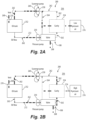
Fig. 2A is a schematic diagram of an embodiment of a system, showing a flow path through the valve ofFig. 1A , when the valve is in the first state; -
Fig. 2B is a schematic diagram of an embodiment of the system ofFig. 2A , showing a flow path through the valve ofFig. 1A , when the valve is in the second state; -
Fig. 3A is a schematic cross-sectional view of an embodiment of a valve in accordance with this disclosure, showing the valve in a first state; -
Fig. 3B is a schematic cross-sectional view of an embodiment of the valve ofFig. 3A , showing the valve in a second state; -
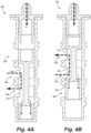
Fig. 4A is a schematic cross-sectional view of an embodiment of a valve in accordance with this disclosure, showing the valve in a first state; -
Fig. 4B is a schematic cross-sectional view of an embodiment of the valve ofFig. 4A , showing the valve in a second state; -
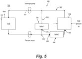
Fig. 5 is a schematic diagram of an embodiment of a system, showing a flow path through an embodiment of one or more valves; -
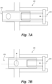
Fig. 6A is a schematic cross-sectional view of an embodiment of a normally-open valve shown inFig. 5 , the valve shown in an open position; -
Fig. 6B is a schematic cross-sectional view of the valve ofFig. 6A shown in a closed position; -
Fig. 7A is a schematic cross-sectional view of an embodiment of a normally-closed valve shown inFig. 5 , the valve shown in a closed position; -
Fig. 7B is a schematic cross-sectional view of the valve ofFig. 7A shown in an open position; - Reference will now be made to the drawings wherein like reference numerals identify similar structural features or aspects of the subject disclosure. For purposes of explanation and illustration, and not limitation, an illustrative view of an embodiment of a valve in accordance with the disclosure is shown in
Figs. 1A and 1B and is designated generally byreference character 100. Other embodiments and/or aspects of this disclosure are shown inFigs. 2A-7B . - In accordance with at least one aspect of this disclosure, there is provided a
valve 100. Thevalve 100 includes a valve housing 102 (e.g., a cylindrical housing as shown) defining aflow inlet 104,first flow outlet 106, asecond flow outlet 108, and areference port 110. The valve includes a valve body 112 (e.g., a piston as shown) within thevalve housing 102 configured to move within thehousing 102 between a first position (e.g., as shown inFig. 1A ) and a second position (e.g., as shown inFig. 1B ) based on a pressure at thereference port 110. In the first position, thevalve 100 is configured to fluidly communicate theflow inlet 104 and thefirst flow outlet 106 and in the second position thevalve 100 is configured to fluidly communicate theflow inlet 104 and thesecond flow outlet 108. Thepiston 112 can includeinternal flow channels 114 which allow flow to pass through thepiston 112 to thefirst flow outlet 106 in the first position. In the second position, flow that passes through theinternal flow channels 114 is blocked by the piston from flowing to thereference port 110. - A biasing
member 116 can be connected to thepiston 112 and to thevalve housing 102 configured to bias thepiston 112 to the first position. The biasingmember 116 also allows thepiston 112 to move to the second position based on pressure at thereference port 110. The biasing member can be any suitable biasing member, for example including any one or more of a flexible member, a spring, a Belleville washer, a resilient member, or the like. In embodiments, a construction of thepiston 112 and a biasing strength of the biasingmember 116 can be selected such that when a fluid of the aircraft fluid system (e.g.,system piston 112 through theflow inlet 104, a force produced by the fluid on thepiston 112 overcomes the biasing strength and thereby moves the piston toward the second position. The construction of thevalve housing 102 and thepiston 112 can be cylindrical as described herein, however it is contemplated that other geometries of thevalve housing 102,piston 112, other biasing member weights, and/or configurations of thepiston 112 and biasingmember 116 within thevalve housing 102 are contemplated herein. - In embodiments, the piston can be translatable axially in the
housing 102 and has opposed axial sides, the flow inlet can be disposed on one of the opposed axial sides, and the reference port is fluidly open to the other one of the opposed axial sides. For example, thepiston 112 can have afirst end 118 and asecond end 120, and thevalve housing 102 can have afirst end 122 and asecond end 124. In embodiments, theflow inlet 104 can be at thefirst end 122 of thevalve housing 102 and thereference port 110 can be at thesecond end 124 of the valve housing. The biasingmember 116 can be disposed at thesecond end 124 of thevalve housing 102, between the reference port 110 (or at least partially within the reference port) and thesecond end 120 of thepiston 112. In embodiments, the reference port can be fluidly open to thepiston 112 at a location relative to thepiston 112 that is selected such that fluid pressure applied to thereference port 110 opposes fluid pressure applied to the flow inlet 104 (e.g., on opposite sides of the piston 112). - In certain embodiments, the
valve housing 102 can define a longitudinal axis A extending from thefirst end 122 of thevalve housing 102 to thesecond end 124 of thevalve housing 102 and thepiston 112 can be configured to translate axially within thevalve housing 102 along the longitudinal axis A. In certain embodiments, (e.g., as shown inFig. 1A and 1B ), anopening 126 of theflow inlet 104 can be defined at thefirst end 122 of thevalve housing 102, opening axially such that a flow axis B at theflow inlet 104 is parallel to the longitudinal axis A. Anopening 128 of thereference port 110 can be defined at thesecond end 124 of thevalve housing 102, opening axially and in an opposite direction of theopening 126 of theflow inlet 104 such that a flow axis C of thereference port 110 is parallel to the longitudinal axis A. - In certain embodiments, such as shown in
Figs. 1A and 1B , anopening 130 of thefirst flow outlet 130 and anopening 132 of thesecond flow outlet 108 can be positioned such that a flow axis D of the first flow outlet and a flow axis E of the second flow outlet are oriented orthogonal to the longitudinal axis A. Stated differently, theopenings first flow outlet 106 and thesecond flow outlet 108 are rotated 90 degrees relative to theopening 126flow inlet 104. As shown inFigs. 1A and 1B , theflow inlet 104 and thesecond flow outlet 108 can be the same size (e.g., therespective openings first flow outlet 106 can be a different size relative to theflow inlet 104 and the second flow outlet 108 (e.g., opening 130 is smaller thanopenings - In accordance with at least one aspect of this disclosure, as shown in
Fig. 2A and 2B , there is provided asystem 200. In embodiments, thesystem 200 can include a first pump 250 (e.g., a pressure pump) configured to drive oil to from anoil tank 252 to acavity 254 of anaircraft engine 256, a second pump 258 (e.g., a scavenge pump) configured drive spent oil from thecavity 254 back to theoil tank 252, and a valve disposed downstream of thefirst pump 252 and upstream of thecavity 254. The valve shown inFig. 2A and 2B can be the same or similar tovalve 100 as shown inFigs. 1A and 1B . For clarity and ease of understanding, thesystem 200 will be described as having thevalve 100 therein, however, in view of this disclosure, one having ordinary skill in the art would readily appreciate that any embodiment of the valve shown and described herein (e.g.,valves 300, 400) can be used in thesystem 200. - The
oil tank 252 is disposed upstream of thefirst pump 250 and downstream of thesecond pump 258 and thecavity 254 disposed downstream of thefirst pump 250 and upstream of thesecond pump 258. Thevalve 100 can be configured to provide flow to thesecond pump 258 in both a first state and a second state of the valve to continuously lubricate (e.g., via lubrication path 260) thesecond pump 258 regardless of the state of thevalve 100. In embodiments, in the first state of the valve 100 (e.g., wherein thepiston 112 is in the first position as shown inFig. 1A ), flow from theoil tank 252 is allowed to pass from thevalve 100 directly to thesecond pump 258 and is blocked from passing to the cavity 254 (e.g., as shown inFig. 2A , where the flow path to thesecond pump 258 is shown in solid lines and the flow path to thecavity 254 is shown in hashed lines). In the second state of the valve 100 (e.g., wherein thepiston 112 is in the second position as shown inFig. 1B ), flow from theoil tank 252 is allowed to pass from thevalve 100 to thecavity 254 and is blocked from passing directly to the second pump 258 (e.g., as shown inFig. 2B , where the flow path to thesecond pump 258 is shown in hashed lines and the flow path to thecavity 254 is shown in solid lines). In this state, the oil does still pass from though thevalve 100 to thesecond pump 258, but it must go to thecavity 254 first. In embodiments, the first state of thevalve 100 can correspond to a startup and/or transient (e.g., ramp up) condition of theaircraft engine 256 and the second state of thevalve 100 can correspond to an operational and/or idle condition of theaircraft engine 256. - The
system 200 can include aprimary conduit 262 for fluidly communicating in series, theoil tank 252, thefirst pump 250, thevalve 100, thecavity 254, and thesecond pump 258 in a circuit. Abypass conduit 264 can be included for fluidly communicating in series, thevalve 100, and thesecond pump 258, bypassing thecavity 254. - In the first state of the
valve 100, flow from the first pump is blocked from passing though thevalve 100 to thecavity 254 via theprimary conduit 262 but flow from thefirst pump 250 is passed through thevalve 100 to thesecond pump 258 via thebypass conduit 264. This is shown inFig. 2A . In the second state of thevalve 100, flow from thefirst pump 250 passes though thevalve 100 to thecavity 254 and to thesecond pump 258 via theprimary conduit 262 but is blocked from passing through thevalve 100 to thesecond pump 258 via thebypass conduit 264. This is shown inFig. 2B . The valve therefore allows oil to be passed from theoil tank 252 to thesecond pump 258 when thevalve 100 is both open and closed to thecavity 254 to continuously supply thelubrication path 260 of thesecond pump 258. This ensure one or more components of the second pump 258 (e.g., journal bearings) are always lubricated during operation of thesecond pump 258. - With reference now to
Figs. 1A to 2B , thevalve 100 can be configured to move between the first state and the second state based on a single pressure reference (e.g., a pressure supplied to thesecond side 120 of thepiston 112 via the reference port 110). In certain embodiments, the single pressure reference can be a lowpressure air flow 268 fluidly connected to avent 270 of theoil tank 252. When thevalve 100 is in the first state, a pressure of theoil flow 272 on thefirst side 118 of thepiston 112 is less than a pressure of the lowpressure air flow 268 plus a bias force (e.g., supplied by the biasing member 116) on thesecond side 120 of thepiston 112. The lowpressure air flow 268 and the bias force maintain thevalve 100 in the first state while theoil flow 272 pressurizes and rises to a pressure great enough to overcome the lowpressure air flow 268 and the bias force. When the pressure of theoil flow 272 on thefirst side 118 of thepiston 112 has increased to a pressure greater than the pressure of the lowpressure air flow 268 plus the bias force on thesecond side 120 of thepiston 112, thepiston 112 moves into the second position, placing thevalve 100 in the second state. Theoil flow 272 maintains thevalve 100 in the second state until the pressure of theoil flow 272 then drops below the pressure of the lowpressure air flow 268 and the bias force, moving thevalve 100 back into the first state. It should be understood thatFigs. 2A and 2B are schematic and therefore the relative positioning of any inlets/outlets of thevalve 100 shown inFigs. 2A and 2B may not correspond exactly to the relative positioning of any inlets/outlets of the valve shown inFigs. 1A and 1B . In certain embodiments, the low pressure reference can include oil, and can be a hydrostatic pressure of the oil in theoil tank 252, which may be suitable for industrial or grounded engines. - In certain embodiments, with reference now to
Figs. 3A and 3B , thevalve 300 can have similar components as shown and described with respect tovalve 100. For brevity, the description of common elements that have been described above are not repeated with respect toFigs. 3A and 3B . In thevalve 300, thereference port 310 can be a first reference port, and thevalve 300 can include asecond reference port 334 defined in thevalve housing 302 opposite thefirst reference port 310. Thesecond reference port 334 can be defined in thevalve housing 302 in the same location as theflow inlet 104 ofvalve 100, and theflow inlet 304 can be defined in the side of thevalve housing 302 between the first andsecond flow outlets piston 312 moves between the first and second position based on pressure at thefirst reference port 310 and thesecond reference port 334. - The first pressure reference can be a low
pressure air flow 268 fluidly connected to thevent 270 of theoil tank 252 and a second pressure reference can be a highpressure air flow 274 fluidly connected tocompressor section 276 of theaircraft engine 256. When thevalve 300 is in the first state the pressure of the highpressure air flow 274 on thefirst side 118 of thepiston 312 is less than a pressure of the lowpressure air flow 268 plus the bias force acting on thesecond side 120 of thepiston 312. The lowpressure air flow 268 and the bias force maintain thevalve 300 in the first state while the aircraft engine ramps up, the highpressure air flow 274 pressurizes further, rising to a pressure great enough to overcome the lowpressure air flow 268 and the bias force. When the pressure of the highpressure air flow 274 on thefirst side 118 of thepiston 312 has increased to a pressure greater than the pressure of the lowpressure air flow 268 plus the bias force on thesecond side 120 of thepiston 312, thepiston 312 moves into the second position, placing thevalve 300 in the second state. The highpressure air flow 274 maintains thevalve 300 in the second state during idle and operational conditions of theaircraft engine 256, until the pressure of the highpressure air flow 274 then drops below the pressure of the lowpressure air flow 268 and the bias force (e.g., as theengine 256 shuts down), moving thevalve 300 back into the first state. - In certain embodiments, as shown in
Figs. 4A and 4B , thevalve 400 can have similar components as shown and described with respect tovalve 300 and can operate in the same or a similar manner. For brevity, the description of common elements that have been described above with respect tovalve 300 and shown inFigs. 3A and 3B are not repeated with respect toFigs. 4A and 4B . In thevalve 400, theopening 426 of theflow inlet 404, theopening 430 of thefirst flow outlet 406, and theopening 432 of thesecond flow outlet 408 can all be same size (e.g., all have the same diameter). Further, thevalve 400 can have a single reference port 410, as shown, and operate similar to that ofvalve 100, or thevalve 400 can have two reference ports and operate similar tovalve 300. If two reference ports are included invalve 400, flow channels 414 can be eliminated. - Traditional valves can be understood as conditional statements such as: if pressure difference is less than a threshold, do not send flow to flow outlets. However, such traditional valves can be used to only open and close once per engine mission, or can be used to regulate pressure by reacting to varying pressure references to bypass a proportionally varying amount of oil. Thus, traditional valves may not be optimal in certain application, such as the
system 100 shown inFigs. 2A and 2B because opening the outlet port open only occurs above a minimum pressure, or when pressure differential, is reached and it does not allow to switch between bypass ports depending on pressure differential. - Embodiments of the
valve system 200 as shown and described herein can feature an open port when the valve is in a closed position. The valve (e.g., valve 100) can have a single low pressure reference, as depicted inFigs. 1A and 1B , or the valve (e.g.,valve 300, 400) can have or a low pressure reference and a high pressure reference, e.g., as depicted inFigs. 3A-4B .Figs. 1A ,3A , and4A show the valves in both the closed and open positions, where the valve always allows flow to an outlet port (whether to the bypass conduit or the primary conduit as shown inFigs. 2A and 2B . In embodiments, the bypass ports (e.g., thefirst flow outlet inlet - In embodiments, the cavity sealing at a power condition from idle to maximum power rating can be achieved by surrounding the cavity with high pressure air rushing in controlled gap seals. This sealing mechanism may not be efficient in the start-up or transient conditions from engine shut down to GI. Including an oil delay valve upstream of the cavity (e.g., as shown) to prevent oil flow from reaching the cavity before the cavity reaches a sufficient pressure differential between the cavity and its surroundings can be beneficial. Further, embodiments include an existing scavenge pump from an existing engine that does not have its oil delay, which can reduce total part number for the
system 200. In order to use the existing scavenge pump, the journal bearings need to be lubricated from the pressure side of each scavenge pump stage to minimize friction, power losses and wear between the rotating shaft and the static bores in the pump housing. If a traditional valve was used in thesystem 200, it would cut off flow of oil to the scavenge pump in sub-idle conditions and would force the scavenge pump journal bearings to run dry because no scavenge flow would come from the cavity during the oil delay period. This could significantly impact the useful life of the pump. Accordingly, embodiments of thevalve Fig. 2A ). Embodiments therefore allow thesystem 200 to re-use a non-oil delay scavenge pump on an oil delay cavity. - In accordance with at least one aspect of this disclosure, and as shown in
Figs. 5-7B there is provided afluid system 500 for anaircraft engine 556. While thefluid system 500 is described herein with respect to certain fluids, e.g., oil and/or air, it is envisioned that thefluid system 500 can use suitable for use with fluids other than oil, and thefluid system 500 can be used in one or more fluid applications within aerospace not specifically described herein. - In embodiments, e.g., as shown, the
fluid system 500 can include a pumpedfluid circulation circuit 562 including afluid tank 552, wherein thefluid circulation circuit 562 is configured to circulate a fluid through at least a part of theaircraft engine 556. Thefluid system 500 can include means, in the fluid circulation circuit, for selectively directing the fluid of thefluid circulation circuit 562 as a function of a pressure of fluid in the fluid circulation circuit to one of apart 554 of theaircraft engine 556 and/or afluid bypass 564 in the fluid circulation circuit that is fluidly upstream of thepart 554 of theaircraft engine 556. - In embodiments, the means for selectively directing the fluid can include a normally-closed
valve 600 disposed, when thefluid system 500 is in use, fluidly between aninlet 578 of thefluid bypass 564 and aninlet 580 of thepart 554 of theaircraft engine 556. The means for selectively directing the fluid can also include and a normally-open valve 700 disposed in thefluid bypass 564. In embodiments, thevalves valves valves valves aircraft engine 556 spools up and pressure in thefluid system 500 increases, the normally-closedvalve 600 opens to allow fluid to pass to the part 554 (e.g., a cavity) of theengine 556 and, either simultaneously or sequentially (as described further below) the normally-open valve 700 closes as a result of the pressure change. - In embodiments, the normally-closed
valve 600 can be openable by fluid in thefluid circulation circuit 562 acting on aninlet 604 of the normally-closedvalve 600 when pressure of the fluid at theinlet 604 of the normally-closedvalve 604 exceeds a first predefined pressure threshold (e.g., as shown inFigs. 7A and 7B ). The normally-open valve 700 can be closeable by fluid in thefluid circulation circuit 562 acting on aninlet 704 of the normally-open valve 700 when pressure of the fluid at theinlet 704 of the normally-open valve 700 exceeds a second predefined pressure threshold (e.g., as shown inFigs. 6A and 6B ). - In certain embodiments, the first predefined pressure threshold can be lower than the second predefined pressure threshold, for example so that the normally-closed
valve 600 is configured to open first to begin feeding thepart 554 of theengine 556 before the normally-open valve 700 closes. In certain embodiments, the first predefined pressure threshold can be equal to the second predefined pressure threshold, for example so that a simultaneous switchover from fluid being directed to thebypass 564 to fluid being directed to thepart 554 of theengine 556 can occur. - In certain embodiments, the means for selectively directing the fluid can include a single valve (e.g., any one of
valves fluid circulation circuit 562, which can be similar to thesystem 200 as shown inFigs. 2A and 2B . The valve can include an inlet disposed fluidly upstream of an inlet of the fluid bypass, a first outlet fluidly connected to the inlet of the valve and to the inlet of the fluid bypass, a second outlet fluidly connected to the inlet of the valve and to an inlet of the part of the aircraft engine when the fluid system is installed in the aircraft engine, and means for diverting at least substantially all fluid flow from the inlet to one of the first outlet and the second outlet as fluid pressure at the inlet of the valve rises above a predefined pressure threshold. In embodiments, the means for diverting may be passive (e.g., as shown) or may be active (e.g., using an actuator with sensors). - In accordance with at least one aspect of this disclosure, there is provided an aircraft engine (e.g.,
engine 256, 556). The aircraft engine can include any one or more of thevalves cavity 254, 554) of the aircraft engine, a pumped oil circulation circuit (e.g.,circuit 262, 562) including an oil tank (e.g.,tank 252, 552) and the cavity, and a bypass conduit (e.g.,conduit 264, 564) fluidly connecting the first flow outlet of the valve to a location in the oil circulation circuit that is downstream of the cavity. In embodiments, the flow inlet and the second flow outlet of the valve are part of the oil circulation circuit at a location fluidly upstream of the cavity. - In embodiments, the valve can also include a reference port (e.g.,
port valve body 112 at a location relative to the body that is selected such that fluid pressure applied to the reference port opposes fluid pressure applied to the flow inlet, and the reference port can be connected to the oil tank to receive fluid pressure from the oil tank. In embodiments, the reference port can be connected to the oil tank at a location in the oil tank that is above a maximum oil level of the oil tank. In embodiments, the engine can further include an oil pump (e.g., pump 258, 558) in the oil circulation circuit at a location downstream of the location in the oil circulation circuit that is downstream of the cavity to which the bypass conduit fluidly connects the first flow outlet of the valve, and wherein the oil pump is operable to pump oil toward the oil tank. - As the engine power and cavity versus surrounding pressure, increases, the
oil delay valve valve - Those having ordinary skill in the art understand that any numerical values disclosed herein can be exact values or can be values within a range. Further, any terms of approximation (e.g., "about", "approximately", "around") used in this disclosure can mean the stated value within a range. For example, in certain embodiments, the range can be within (plus or minus) 20%, or within 10%, or within 5%, or within 2%, or within any other suitable percentage or number as appreciated by those having ordinary skill in the art (e.g., for known tolerance limits or error ranges).
- The articles "a", "an", and "the" as used herein and in the appended claims are used herein to refer to one or to more than one (i.e., to at least one) of the grammatical object of the article unless the context clearly indicates otherwise. By way of example, "an element" means one element or more than one element.
- The phrase "and/or," as used herein in the specification and in the claims, should be understood to mean "either or both" of the elements so conjoined, i.e., elements that are conjunctively present in some cases and disjunctively present in other cases. Multiple elements listed with "and/or" should be construed in the same fashion, i.e., "one or more" of the elements so conjoined. Other elements may optionally be present other than the elements specifically identified by the "and/or" clause, whether related or unrelated to those elements specifically identified. Thus, as a non-limiting example, a reference to "A and/or B", when used in conjunction with open-ended language such as "comprising" can refer, in one embodiment, to A only (optionally including elements other than B); in another embodiment, to B only (optionally including elements other than A); in yet another embodiment, to both A and B (optionally including other elements); etc.
- As used herein in the specification and in the claims, "or" should be understood to have the same meaning as "and/or" as defined above. For example, when separating items in a list, "or" or "and/or" shall be interpreted as being inclusive, i.e., the inclusion of at least one, but also including more than one, of a number or list of elements, and, optionally, additional unlisted items. Only terms clearly indicated to the contrary, such as "only one of' or "exactly one of," or, when used in the claims, "consisting of," will refer to the inclusion of exactly one element of a number or list of elements. In general, the term "or" as used herein shall only be interpreted as indicating exclusive alternatives (i.e., "one or the other but not both") when preceded by terms of exclusivity, such as "either," "one of," "only one of," or "exactly one of."
- Any suitable combination(s) of any disclosed embodiments and/or any suitable portion(s) thereof are contemplated herein as appreciated by those having ordinary skill in the art in view of this disclosure.
- The embodiments of the present disclosure, as described above and shown in the drawings, provide for improvement in the art to which they pertain. While the apparatus and methods of the subject disclosure have been shown and described, those skilled in the art will readily appreciate that changes and/or modifications may be made thereto without departing from the scope of the subject disclosure.
Claims (15)
- An oil system for an aircraft engine, comprising:a first pump (250) configured to drive oil to from an oil tank (252) to a cavity (254) of an aircraft engine (256);a second pump (258) configured to drive spent oil from the cavity (254) back to the oil tank (252); anda valve (100) disposed downstream of the first pump (250) and upstream of the cavity (254), wherein in a first state of the valve (100), flow from the oil tank (252) is allowed to pass from the valve (100) directly to the second pump (258) and is blocked from passing to the cavity (254), and in a second state of the valve (100), flow from the oil tank (252) is allowed to pass from the valve (100) to the cavity (254) and is blocked from passing directly to the second pump (258), wherein the valve (100) continuously lubricates the second pump (258) regardless of the state of the valve (100).
- The oil system of claim 1, wherein the oil tank (252) is disposed upstream of the first pump (250) and downstream of the second pump (258), and the cavity (254) is disposed downstream of the first pump (250) and upstream of the second pump (258).
- The oil system of claim 1 or 2, further comprising a primary conduit (262) for fluidly communicating in series, the oil tank (252), the first pump (250), the valve (100), the cavity (254), and the second pump (258).
- The oil system of any preceding claim, further comprising a bypass conduit (264) for fluidly communicating in series, the valve (100), and the second pump (258), bypassing the cavity (254).
- The oil system of claim 4, wherein in the first state of the valve (100), the valve (100) is configured to block flow from the first pump (250) from passing though the valve (100) to the cavity (254) via the primary conduit (262) and to allow flow from the first pump (250) to pass through the valve (100) to the second pump (258) via the bypass conduit (264).
- The oil system of claim 4 or 5 when dependent on claim 3, wherein in the second state of the valve (100), the valve (100) is configured to allow flow from the first pump (250) to pass though the valve (100) to the cavity (254) via the primary conduit (262) and to block flow from the first pump (250) from passing through the valve (100) to the second pump (258) via the bypass conduit (264).
- The oil system of any preceding claim, wherein the valve (100) is configured to move between the first state and the second state based on a single pressure reference, wherein the single pressure reference is a low pressure air flow fluidly connected to a vent (270) of the oil tank (252).
- A valve for an aircraft fluid system, such as an oil system, the valve (100) comprising:a valve housing (102) defining a flow inlet (104), a first flow outlet (106) fluidly connected to the flow inlet (104), and a second flow outlet (108) fluidly connected to the flow inlet (104);a body (112) within the valve housing (102) moveable within the valve housing (102) between:a first state in which the body (112) fluidly connects the flow inlet (104) to the first flow outlet (106) while fluidly disconnecting the flow inlet (104) from the second flow outlet (108); anda second state in which the body (112) fluidly connects the flow inlet (104) to the second flow outlet (108) while fluidly disconnecting the flow inlet (104) from the first flow outlet (106); anda biasing member (116) operatively connected to the body (112) and biasing the body (112) to the first state;wherein a construction of the body (112) and a biasing strength of the biasing member (116) are selected such that when a fluid of the aircraft fluid system (200) acts at a predefined pressure on the body (112) through the flow inlet (104), a force produced by the fluid on the body (112) overcomes the biasing strength and thereby moves the body (112) toward the second position.
- The valve of claim 8, further comprising a reference port (110) fluidly open to the body (112) at a location relative to the body (112) that is selected such that fluid pressure applied to the reference port (110) opposes fluid pressure applied to the flow inlet (104).
- The system of claim 8 or 9, wherein the valve housing (102) is cylindrical and the body (112) is a piston (112) translatable within the valve housing (102).
- The valve of claim 10, wherein:the piston (112) is translatable axially in the valve housing (102) and has opposed axial sides (118, 120),the flow inlet (104) is disposed on one of the opposed axial sides (118), andthe reference port (110) is fluidly open to the other one of the opposed axial sides (120).
- The valve of any of claims 8 to 11, wherein the flow inlet (104) and the first flow outlet (106) are different sizes, and wherein the flow inlet (104) and the second flow outlet (108) are the same size.
- An aircraft engine, comprising:the valve (100) of any of claims 8 to 12;a compressor section (276) fluidly connected to air to a cavity (254) of the aircraft engine (256),a pumped oil circulation circuit (562) including an oil tank (252) and the cavity (254); anda bypass conduit (264) fluidly connecting the first flow outlet (106) of the valve (100) to a location in the oil circulation circuit (562) that is downstream of the cavity (254); andwherein the flow inlet (104) and the second flow outlet (108) of the valve (100) are part of the oil circulation circuit (562) at a location fluidly upstream of the cavity (254).
- The aircraft engine of claim 13, wherein:the valve (100) further comprises a or the reference port (110) fluidly open to the body (112) at a or the location relative to the body (112) that is selected such that fluid pressure applied to the reference port (110) opposes fluid pressure applied to the flow inlet (104), andthe reference port (110) is connected to the oil tank (252) to receive fluid pressure from the oil tank (252).
- The aircraft engine of claim 14, wherein the reference port (110) is connected to the oil tank (252) at a location in the oil tank (252) that is above a maximum oil level of the oil tank (252), and optionally further comprising an oil pump (258) in the oil circulation circuit (562) at a location downstream of the location in the oil circulation circuit (562) that is downstream of the cavity (254) to which the bypass conduit (264) fluidly connects the first flow outlet (106) of the valve (100), and wherein the oil pump (258) is operable to pump oil toward the oil tank (252).
Applications Claiming Priority (1)
| Application Number | Priority Date | Filing Date | Title |
|---|---|---|---|
| US18/151,424 US12297758B2 (en) | 2023-01-07 | 2023-01-07 | Bypass valve |
Publications (2)
| Publication Number | Publication Date |
|---|---|
| EP4397842A2 true EP4397842A2 (en) | 2024-07-10 |
| EP4397842A3 EP4397842A3 (en) | 2024-07-31 |
Family
ID=89535921
Family Applications (1)
| Application Number | Title | Priority Date | Filing Date |
|---|---|---|---|
| EP24150788.8A Pending EP4397842A3 (en) | 2023-01-07 | 2024-01-08 | Bypass valve |
Country Status (3)
| Country | Link |
|---|---|
| US (2) | US12297758B2 (en) |
| EP (1) | EP4397842A3 (en) |
| CA (1) | CA3223437A1 (en) |
Families Citing this family (3)
| Publication number | Priority date | Publication date | Assignee | Title |
|---|---|---|---|---|
| US12297758B2 (en) * | 2023-01-07 | 2025-05-13 | Pratt & Whitney Canada Corp. | Bypass valve |
| US12480596B2 (en) * | 2024-01-18 | 2025-11-25 | Pratt & Whitney Canada Corp. | Multi-function fluid control valve |
| US20260043338A1 (en) * | 2024-08-06 | 2026-02-12 | Pratt & Whitney Canada Corp. | Spool valve for aircraft engine |
Family Cites Families (15)
| Publication number | Priority date | Publication date | Assignee | Title |
|---|---|---|---|---|
| US5111653A (en) * | 1990-04-11 | 1992-05-12 | Woodward Governor Company | Fuel delivery system with capacity monitor |
| US5215444A (en) * | 1990-10-24 | 1993-06-01 | Woodward Governor Company | System for controlling oil viscosity and cleanliness |
| US5711145A (en) * | 1995-10-10 | 1998-01-27 | Alliedsignal, Inc. | Combined pressurizing, flow measuring and flow splitting valve |
| ES2193606T3 (en) | 1997-12-12 | 2003-11-01 | Allied Signal Inc | PROPORTIONAL DERIVATION VALVE AND BALANCED FORCES. |
| DE102007058954A1 (en) * | 2007-12-07 | 2009-06-10 | Rolls-Royce Deutschland Ltd & Co Kg | Gas turbine oil supply system and method of operating a gas turbine bearing oil supply |
| FR2966507B1 (en) * | 2010-10-20 | 2015-03-20 | Turbomeca | LUBRICATION DEVICE WITH DERIVATION VALVE |
| US10247095B2 (en) * | 2012-09-28 | 2019-04-02 | United Technologies Corporation | Reduced trim flow gas turbine engine oil system |
| WO2015047577A1 (en) * | 2013-09-26 | 2015-04-02 | United Technologies Corporation | Gas turbine engine with split lubrication system |
| US20160245117A1 (en) * | 2015-02-24 | 2016-08-25 | United Technologies Corporation | In-line deaerator device for windmill-auxiliary oil system for fan drive gear system |
| FR3055664B1 (en) * | 2016-09-02 | 2020-05-01 | Safran Power Units | FUEL DOSING UNIT FOR A TURBOMACHINE |
| IT201900011391A1 (en) * | 2019-07-10 | 2021-01-10 | Ge Avio Srl | LUBRICATION SYSTEM |
| US11655731B2 (en) * | 2020-02-14 | 2023-05-23 | Pratt & Whitney Canada Corp. | Oil distribution system for gas turbine engine |
| EP4635853A3 (en) * | 2021-06-11 | 2025-11-05 | RTX Corporation | Oil circulation system for hybrid electric engine |
| US12000495B2 (en) * | 2021-07-20 | 2024-06-04 | Pratt & Whitney Canada Corp. | Pressure referenced valve |
| US12297758B2 (en) * | 2023-01-07 | 2025-05-13 | Pratt & Whitney Canada Corp. | Bypass valve |
-
2023
- 2023-01-07 US US18/151,424 patent/US12297758B2/en active Active
- 2023-12-15 CA CA3223437A patent/CA3223437A1/en active Pending
-
2024
- 2024-01-08 EP EP24150788.8A patent/EP4397842A3/en active Pending
-
2025
- 2025-04-25 US US19/189,991 patent/US20250250916A1/en active Pending
Also Published As
| Publication number | Publication date |
|---|---|
| US20240229688A1 (en) | 2024-07-11 |
| US12297758B2 (en) | 2025-05-13 |
| US20250250916A1 (en) | 2025-08-07 |
| CA3223437A1 (en) | 2025-04-05 |
| EP4397842A3 (en) | 2024-07-31 |
Similar Documents
| Publication | Publication Date | Title |
|---|---|---|
| EP4397842A2 (en) | Bypass valve | |
| US9896995B2 (en) | Lubricant feed mechanism for turbocharger | |
| EP1790855B1 (en) | Hydraulic pump system with variable flow and pressure | |
| US9279367B2 (en) | Pressure regulating valve for aircraft engine | |
| US8641395B2 (en) | Compressor | |
| US8881870B2 (en) | Recirculation valve in an aircraft engine | |
| US20210088043A1 (en) | Inline piston pump | |
| US10677245B2 (en) | Variable displacement pump | |
| US20180320692A1 (en) | Coolant pump for the automotive industry | |
| US20170356448A1 (en) | Screw Compressor with Oil Shutoff and Method | |
| US10393313B2 (en) | Oil circuit of an aircraft engine | |
| KR101867251B1 (en) | A method of arranging the lubrication of a controllable pitch propeller arrangement of a marine vessel and a lubrication arrangement therefor | |
| US10865712B2 (en) | Valve assembly with oil shut-off valve | |
| KR100225994B1 (en) | Hydraulic setting device | |
| US5018947A (en) | Screw type vacuum pump | |
| CN117588893A (en) | Liquid cooling module | |
| JP6469155B2 (en) | Fluid pressure circuit | |
| JP6165610B2 (en) | Turbocharger lubrication oil supply mechanism | |
| JP6258772B2 (en) | Internal combustion engine flow control valve | |
| JP6469156B2 (en) | Fluid pressure circuit | |
| US11268509B2 (en) | Variable displacement lubricant vane pump | |
| US20190186560A1 (en) | Popoff valve in hydraulic arrangement for multi-clutch assembly | |
| US20230323944A1 (en) | Hydraulic System for a Transmission of a Motor Vehicle | |
| EP3287678A1 (en) | Poppet valve |
Legal Events
| Date | Code | Title | Description |
|---|---|---|---|
| PUAI | Public reference made under article 153(3) epc to a published international application that has entered the european phase |
Free format text: ORIGINAL CODE: 0009012 |
|
| STAA | Information on the status of an ep patent application or granted ep patent |
Free format text: STATUS: THE APPLICATION HAS BEEN PUBLISHED |
|
| PUAL | Search report despatched |
Free format text: ORIGINAL CODE: 0009013 |
|
| AK | Designated contracting states |
Kind code of ref document: A2 Designated state(s): AL AT BE BG CH CY CZ DE DK EE ES FI FR GB GR HR HU IE IS IT LI LT LU LV MC ME MK MT NL NO PL PT RO RS SE SI SK SM TR |
|
| AK | Designated contracting states |
Kind code of ref document: A3 Designated state(s): AL AT BE BG CH CY CZ DE DK EE ES FI FR GB GR HR HU IE IS IT LI LT LU LV MC ME MK MT NL NO PL PT RO RS SE SI SK SM TR |
|
| RIC1 | Information provided on ipc code assigned before grant |
Ipc: F04D 29/063 20060101ALI20240625BHEP Ipc: F01M 1/02 20060101ALI20240625BHEP Ipc: F01D 25/20 20060101AFI20240625BHEP |
|
| STAA | Information on the status of an ep patent application or granted ep patent |
Free format text: STATUS: REQUEST FOR EXAMINATION WAS MADE |
|
| 17P | Request for examination filed |
Effective date: 20250130 |