EP4397814A1 - Electric work machine - Google Patents
Electric work machine Download PDFInfo
- Publication number
- EP4397814A1 EP4397814A1 EP23209618.0A EP23209618A EP4397814A1 EP 4397814 A1 EP4397814 A1 EP 4397814A1 EP 23209618 A EP23209618 A EP 23209618A EP 4397814 A1 EP4397814 A1 EP 4397814A1
- Authority
- EP
- European Patent Office
- Prior art keywords
- fan
- electric
- flow path
- work machine
- opening portion
- Prior art date
- Legal status (The legal status is an assumption and is not a legal conclusion. Google has not performed a legal analysis and makes no representation as to the accuracy of the status listed.)
- Granted
Links
Images


Classifications
-
- E—FIXED CONSTRUCTIONS
- E02—HYDRAULIC ENGINEERING; FOUNDATIONS; SOIL SHIFTING
- E02F—DREDGING; SOIL-SHIFTING
- E02F3/00—Dredgers; Soil-shifting machines
- E02F3/04—Dredgers; Soil-shifting machines mechanically-driven
- E02F3/28—Dredgers; Soil-shifting machines mechanically-driven with digging tools mounted on a dipper- or bucket-arm, i.e. there is either one arm or a pair of arms, e.g. dippers, buckets
-
- B—PERFORMING OPERATIONS; TRANSPORTING
- B60—VEHICLES IN GENERAL
- B60K—ARRANGEMENT OR MOUNTING OF PROPULSION UNITS OR OF TRANSMISSIONS IN VEHICLES; ARRANGEMENT OR MOUNTING OF PLURAL DIVERSE PRIME-MOVERS IN VEHICLES; AUXILIARY DRIVES FOR VEHICLES; INSTRUMENTATION OR DASHBOARDS FOR VEHICLES; ARRANGEMENTS IN CONNECTION WITH COOLING, AIR INTAKE, GAS EXHAUST OR FUEL SUPPLY OF PROPULSION UNITS IN VEHICLES
- B60K1/00—Arrangement or mounting of electrical propulsion units
- B60K1/04—Arrangement or mounting of electrical propulsion units of the electric storage means for propulsion
-
- B—PERFORMING OPERATIONS; TRANSPORTING
- B60—VEHICLES IN GENERAL
- B60K—ARRANGEMENT OR MOUNTING OF PROPULSION UNITS OR OF TRANSMISSIONS IN VEHICLES; ARRANGEMENT OR MOUNTING OF PLURAL DIVERSE PRIME-MOVERS IN VEHICLES; AUXILIARY DRIVES FOR VEHICLES; INSTRUMENTATION OR DASHBOARDS FOR VEHICLES; ARRANGEMENTS IN CONNECTION WITH COOLING, AIR INTAKE, GAS EXHAUST OR FUEL SUPPLY OF PROPULSION UNITS IN VEHICLES
- B60K11/00—Arrangement in connection with cooling of propulsion units
- B60K11/02—Arrangement in connection with cooling of propulsion units with liquid cooling
- B60K11/04—Arrangement or mounting of radiators, radiator shutters, or radiator blinds
-
- B—PERFORMING OPERATIONS; TRANSPORTING
- B60—VEHICLES IN GENERAL
- B60K—ARRANGEMENT OR MOUNTING OF PROPULSION UNITS OR OF TRANSMISSIONS IN VEHICLES; ARRANGEMENT OR MOUNTING OF PLURAL DIVERSE PRIME-MOVERS IN VEHICLES; AUXILIARY DRIVES FOR VEHICLES; INSTRUMENTATION OR DASHBOARDS FOR VEHICLES; ARRANGEMENTS IN CONNECTION WITH COOLING, AIR INTAKE, GAS EXHAUST OR FUEL SUPPLY OF PROPULSION UNITS IN VEHICLES
- B60K11/00—Arrangement in connection with cooling of propulsion units
- B60K11/06—Arrangement in connection with cooling of propulsion units with air cooling
-
- B—PERFORMING OPERATIONS; TRANSPORTING
- B60—VEHICLES IN GENERAL
- B60K—ARRANGEMENT OR MOUNTING OF PROPULSION UNITS OR OF TRANSMISSIONS IN VEHICLES; ARRANGEMENT OR MOUNTING OF PLURAL DIVERSE PRIME-MOVERS IN VEHICLES; AUXILIARY DRIVES FOR VEHICLES; INSTRUMENTATION OR DASHBOARDS FOR VEHICLES; ARRANGEMENTS IN CONNECTION WITH COOLING, AIR INTAKE, GAS EXHAUST OR FUEL SUPPLY OF PROPULSION UNITS IN VEHICLES
- B60K25/00—Auxiliary drives
-
- B—PERFORMING OPERATIONS; TRANSPORTING
- B60—VEHICLES IN GENERAL
- B60L—PROPULSION OF ELECTRICALLY-PROPELLED VEHICLES; SUPPLYING ELECTRIC POWER FOR AUXILIARY EQUIPMENT OF ELECTRICALLY-PROPELLED VEHICLES; ELECTRODYNAMIC BRAKE SYSTEMS FOR VEHICLES IN GENERAL; MAGNETIC SUSPENSION OR LEVITATION FOR VEHICLES; MONITORING OPERATING VARIABLES OF ELECTRICALLY-PROPELLED VEHICLES; ELECTRIC SAFETY DEVICES FOR ELECTRICALLY-PROPELLED VEHICLES
- B60L58/00—Methods or circuit arrangements for monitoring or controlling batteries or fuel cells, specially adapted for electric vehicles
- B60L58/10—Methods or circuit arrangements for monitoring or controlling batteries or fuel cells, specially adapted for electric vehicles for monitoring or controlling batteries
- B60L58/24—Methods or circuit arrangements for monitoring or controlling batteries or fuel cells, specially adapted for electric vehicles for monitoring or controlling batteries for controlling the temperature of batteries
- B60L58/26—Methods or circuit arrangements for monitoring or controlling batteries or fuel cells, specially adapted for electric vehicles for monitoring or controlling batteries for controlling the temperature of batteries by cooling
-
- E—FIXED CONSTRUCTIONS
- E02—HYDRAULIC ENGINEERING; FOUNDATIONS; SOIL SHIFTING
- E02F—DREDGING; SOIL-SHIFTING
- E02F3/00—Dredgers; Soil-shifting machines
- E02F3/04—Dredgers; Soil-shifting machines mechanically-driven
- E02F3/28—Dredgers; Soil-shifting machines mechanically-driven with digging tools mounted on a dipper- or bucket-arm, i.e. there is either one arm or a pair of arms, e.g. dippers, buckets
- E02F3/36—Component parts
-
- E—FIXED CONSTRUCTIONS
- E02—HYDRAULIC ENGINEERING; FOUNDATIONS; SOIL SHIFTING
- E02F—DREDGING; SOIL-SHIFTING
- E02F9/00—Component parts of dredgers or soil-shifting machines, not restricted to one of the kinds covered by groups E02F3/00 - E02F7/00
- E02F9/08—Superstructures; Supports for superstructures
-
- E—FIXED CONSTRUCTIONS
- E02—HYDRAULIC ENGINEERING; FOUNDATIONS; SOIL SHIFTING
- E02F—DREDGING; SOIL-SHIFTING
- E02F9/00—Component parts of dredgers or soil-shifting machines, not restricted to one of the kinds covered by groups E02F3/00 - E02F7/00
- E02F9/08—Superstructures; Supports for superstructures
- E02F9/0858—Arrangement of component parts installed on superstructures not otherwise provided for, e.g. electric components, fenders, air-conditioning units
- E02F9/0866—Engine compartment, e.g. heat exchangers, exhaust filters, cooling devices, silencers, mufflers, position of hydraulic pumps in the engine compartment
-
- E—FIXED CONSTRUCTIONS
- E02—HYDRAULIC ENGINEERING; FOUNDATIONS; SOIL SHIFTING
- E02F—DREDGING; SOIL-SHIFTING
- E02F9/00—Component parts of dredgers or soil-shifting machines, not restricted to one of the kinds covered by groups E02F3/00 - E02F7/00
- E02F9/08—Superstructures; Supports for superstructures
- E02F9/0858—Arrangement of component parts installed on superstructures not otherwise provided for, e.g. electric components, fenders, air-conditioning units
- E02F9/0883—Tanks, e.g. oil tank, urea tank, fuel tank
-
- E—FIXED CONSTRUCTIONS
- E02—HYDRAULIC ENGINEERING; FOUNDATIONS; SOIL SHIFTING
- E02F—DREDGING; SOIL-SHIFTING
- E02F9/00—Component parts of dredgers or soil-shifting machines, not restricted to one of the kinds covered by groups E02F3/00 - E02F7/00
- E02F9/20—Drives; Control devices
- E02F9/2058—Electric or electro-mechanical or mechanical control devices of vehicle sub-units
- E02F9/2062—Control of propulsion units
- E02F9/207—Control of propulsion units of the type electric propulsion units, e.g. electric motors or generators
-
- E—FIXED CONSTRUCTIONS
- E02—HYDRAULIC ENGINEERING; FOUNDATIONS; SOIL SHIFTING
- E02F—DREDGING; SOIL-SHIFTING
- E02F9/00—Component parts of dredgers or soil-shifting machines, not restricted to one of the kinds covered by groups E02F3/00 - E02F7/00
- E02F9/20—Drives; Control devices
- E02F9/2058—Electric or electro-mechanical or mechanical control devices of vehicle sub-units
- E02F9/2091—Control of energy storage means for electrical energy, e.g. battery or capacitors
-
- E—FIXED CONSTRUCTIONS
- E02—HYDRAULIC ENGINEERING; FOUNDATIONS; SOIL SHIFTING
- E02F—DREDGING; SOIL-SHIFTING
- E02F9/00—Component parts of dredgers or soil-shifting machines, not restricted to one of the kinds covered by groups E02F3/00 - E02F7/00
- E02F9/20—Drives; Control devices
- E02F9/22—Hydraulic or pneumatic drives
-
- B—PERFORMING OPERATIONS; TRANSPORTING
- B60—VEHICLES IN GENERAL
- B60K—ARRANGEMENT OR MOUNTING OF PROPULSION UNITS OR OF TRANSMISSIONS IN VEHICLES; ARRANGEMENT OR MOUNTING OF PLURAL DIVERSE PRIME-MOVERS IN VEHICLES; AUXILIARY DRIVES FOR VEHICLES; INSTRUMENTATION OR DASHBOARDS FOR VEHICLES; ARRANGEMENTS IN CONNECTION WITH COOLING, AIR INTAKE, GAS EXHAUST OR FUEL SUPPLY OF PROPULSION UNITS IN VEHICLES
- B60K1/00—Arrangement or mounting of electrical propulsion units
-
- B—PERFORMING OPERATIONS; TRANSPORTING
- B60—VEHICLES IN GENERAL
- B60K—ARRANGEMENT OR MOUNTING OF PROPULSION UNITS OR OF TRANSMISSIONS IN VEHICLES; ARRANGEMENT OR MOUNTING OF PLURAL DIVERSE PRIME-MOVERS IN VEHICLES; AUXILIARY DRIVES FOR VEHICLES; INSTRUMENTATION OR DASHBOARDS FOR VEHICLES; ARRANGEMENTS IN CONNECTION WITH COOLING, AIR INTAKE, GAS EXHAUST OR FUEL SUPPLY OF PROPULSION UNITS IN VEHICLES
- B60K11/00—Arrangement in connection with cooling of propulsion units
- B60K11/02—Arrangement in connection with cooling of propulsion units with liquid cooling
-
- B—PERFORMING OPERATIONS; TRANSPORTING
- B60—VEHICLES IN GENERAL
- B60K—ARRANGEMENT OR MOUNTING OF PROPULSION UNITS OR OF TRANSMISSIONS IN VEHICLES; ARRANGEMENT OR MOUNTING OF PLURAL DIVERSE PRIME-MOVERS IN VEHICLES; AUXILIARY DRIVES FOR VEHICLES; INSTRUMENTATION OR DASHBOARDS FOR VEHICLES; ARRANGEMENTS IN CONNECTION WITH COOLING, AIR INTAKE, GAS EXHAUST OR FUEL SUPPLY OF PROPULSION UNITS IN VEHICLES
- B60K1/00—Arrangement or mounting of electrical propulsion units
- B60K2001/003—Arrangement or mounting of electrical propulsion units with means for cooling the electrical propulsion units
-
- B—PERFORMING OPERATIONS; TRANSPORTING
- B60—VEHICLES IN GENERAL
- B60K—ARRANGEMENT OR MOUNTING OF PROPULSION UNITS OR OF TRANSMISSIONS IN VEHICLES; ARRANGEMENT OR MOUNTING OF PLURAL DIVERSE PRIME-MOVERS IN VEHICLES; AUXILIARY DRIVES FOR VEHICLES; INSTRUMENTATION OR DASHBOARDS FOR VEHICLES; ARRANGEMENTS IN CONNECTION WITH COOLING, AIR INTAKE, GAS EXHAUST OR FUEL SUPPLY OF PROPULSION UNITS IN VEHICLES
- B60K1/00—Arrangement or mounting of electrical propulsion units
- B60K2001/003—Arrangement or mounting of electrical propulsion units with means for cooling the electrical propulsion units
- B60K2001/005—Arrangement or mounting of electrical propulsion units with means for cooling the electrical propulsion units the electric storage means
-
- B—PERFORMING OPERATIONS; TRANSPORTING
- B60—VEHICLES IN GENERAL
- B60K—ARRANGEMENT OR MOUNTING OF PROPULSION UNITS OR OF TRANSMISSIONS IN VEHICLES; ARRANGEMENT OR MOUNTING OF PLURAL DIVERSE PRIME-MOVERS IN VEHICLES; AUXILIARY DRIVES FOR VEHICLES; INSTRUMENTATION OR DASHBOARDS FOR VEHICLES; ARRANGEMENTS IN CONNECTION WITH COOLING, AIR INTAKE, GAS EXHAUST OR FUEL SUPPLY OF PROPULSION UNITS IN VEHICLES
- B60K1/00—Arrangement or mounting of electrical propulsion units
- B60K2001/003—Arrangement or mounting of electrical propulsion units with means for cooling the electrical propulsion units
- B60K2001/006—Arrangement or mounting of electrical propulsion units with means for cooling the electrical propulsion units the electric motors
-
- B—PERFORMING OPERATIONS; TRANSPORTING
- B60—VEHICLES IN GENERAL
- B60K—ARRANGEMENT OR MOUNTING OF PROPULSION UNITS OR OF TRANSMISSIONS IN VEHICLES; ARRANGEMENT OR MOUNTING OF PLURAL DIVERSE PRIME-MOVERS IN VEHICLES; AUXILIARY DRIVES FOR VEHICLES; INSTRUMENTATION OR DASHBOARDS FOR VEHICLES; ARRANGEMENTS IN CONNECTION WITH COOLING, AIR INTAKE, GAS EXHAUST OR FUEL SUPPLY OF PROPULSION UNITS IN VEHICLES
- B60K1/00—Arrangement or mounting of electrical propulsion units
- B60K1/04—Arrangement or mounting of electrical propulsion units of the electric storage means for propulsion
- B60K2001/0405—Arrangement or mounting of electrical propulsion units of the electric storage means for propulsion characterised by their position
- B60K2001/0416—Arrangement in the rear part of the vehicle
-
- B—PERFORMING OPERATIONS; TRANSPORTING
- B60—VEHICLES IN GENERAL
- B60K—ARRANGEMENT OR MOUNTING OF PROPULSION UNITS OR OF TRANSMISSIONS IN VEHICLES; ARRANGEMENT OR MOUNTING OF PLURAL DIVERSE PRIME-MOVERS IN VEHICLES; AUXILIARY DRIVES FOR VEHICLES; INSTRUMENTATION OR DASHBOARDS FOR VEHICLES; ARRANGEMENTS IN CONNECTION WITH COOLING, AIR INTAKE, GAS EXHAUST OR FUEL SUPPLY OF PROPULSION UNITS IN VEHICLES
- B60K25/00—Auxiliary drives
- B60K2025/005—Auxiliary drives driven by electric motors forming part of the propulsion unit
-
- B—PERFORMING OPERATIONS; TRANSPORTING
- B60—VEHICLES IN GENERAL
- B60L—PROPULSION OF ELECTRICALLY-PROPELLED VEHICLES; SUPPLYING ELECTRIC POWER FOR AUXILIARY EQUIPMENT OF ELECTRICALLY-PROPELLED VEHICLES; ELECTRODYNAMIC BRAKE SYSTEMS FOR VEHICLES IN GENERAL; MAGNETIC SUSPENSION OR LEVITATION FOR VEHICLES; MONITORING OPERATING VARIABLES OF ELECTRICALLY-PROPELLED VEHICLES; ELECTRIC SAFETY DEVICES FOR ELECTRICALLY-PROPELLED VEHICLES
- B60L2200/00—Type of vehicles
- B60L2200/40—Working vehicles
-
- B—PERFORMING OPERATIONS; TRANSPORTING
- B60—VEHICLES IN GENERAL
- B60Y—INDEXING SCHEME RELATING TO ASPECTS CROSS-CUTTING VEHICLE TECHNOLOGY
- B60Y2200/00—Type of vehicle
- B60Y2200/40—Special vehicles
- B60Y2200/41—Construction vehicles, e.g. graders, excavators
- B60Y2200/412—Excavators
-
- B—PERFORMING OPERATIONS; TRANSPORTING
- B60—VEHICLES IN GENERAL
- B60Y—INDEXING SCHEME RELATING TO ASPECTS CROSS-CUTTING VEHICLE TECHNOLOGY
- B60Y2200/00—Type of vehicle
- B60Y2200/90—Vehicles comprising electric prime movers
- B60Y2200/91—Electric vehicles
-
- B—PERFORMING OPERATIONS; TRANSPORTING
- B60—VEHICLES IN GENERAL
- B60Y—INDEXING SCHEME RELATING TO ASPECTS CROSS-CUTTING VEHICLE TECHNOLOGY
- B60Y2400/00—Special features of vehicle units
- B60Y2400/87—Auxiliary drives
- B60Y2400/89—Cooling systems, e.g. fan drives
-
- E—FIXED CONSTRUCTIONS
- E02—HYDRAULIC ENGINEERING; FOUNDATIONS; SOIL SHIFTING
- E02F—DREDGING; SOIL-SHIFTING
- E02F3/00—Dredgers; Soil-shifting machines
- E02F3/04—Dredgers; Soil-shifting machines mechanically-driven
- E02F3/28—Dredgers; Soil-shifting machines mechanically-driven with digging tools mounted on a dipper- or bucket-arm, i.e. there is either one arm or a pair of arms, e.g. dippers, buckets
- E02F3/30—Dredgers; Soil-shifting machines mechanically-driven with digging tools mounted on a dipper- or bucket-arm, i.e. there is either one arm or a pair of arms, e.g. dippers, buckets with a dipper-arm pivoted on a cantilever beam, i.e. boom
- E02F3/32—Dredgers; Soil-shifting machines mechanically-driven with digging tools mounted on a dipper- or bucket-arm, i.e. there is either one arm or a pair of arms, e.g. dippers, buckets with a dipper-arm pivoted on a cantilever beam, i.e. boom working downwardly and towards the machine, e.g. with backhoes
- E02F3/325—Backhoes of the miniature type
Definitions
- the present invention relates to an electric work machine.
- the first heat exchanger and the second heat exchanger can be cooled in a compact layout.
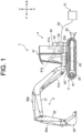
- FIG. 1 is a side view illustrating a schematic configuration of a hydraulic excavator (electric excavator) 1 provided as an example of an electric work machine according to the present embodiment.
- the hydraulic excavator 1 includes a lower traveling body 2, a work instrument 3, and an upper swivel body 4.
- the hydraulic excavator 1 or the upper swivel body 4 is also referred to as a "machine body”.
- a forward direction is a direction in which an operator (manipulator, driver) seated on a driver's seat 41a of the upper swivel body 4 faces front
- a backward direction is a direction opposite to the forward direction. Therefore, in a state where the upper swivel body 4 does not swivel with respect to the lower traveling body 2 (0-degree swivel angle), a front-back direction of the upper swivel body 4 coincides with a direction in which the lower traveling body 2 moves forward and backward.
- a left side is defined as "left”
- a right side is defined as "right”.
- a gravity direction perpendicular to the front-back direction and a left-right direction is defined as an up-down direction, in which an upstream side of the gravity direction is defined as "up”, and a downstream side thereof is defined as “down”.
- the hydraulic excavator 1 is illustrated in a state where the upper swivel body 4 does not swivel with respect to the lower traveling body 2.
- forward is denoted by a symbol "F”, likewise, backward by "B”, rightward by “R”, leftward by “L”, upward by "U”, and downward by "D".
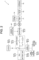
- FIG. 2 is a block diagram schematically illustrating the configuration of electric and hydraulic systems of the hydraulic excavator 1.
- the hydraulic excavator 1 includes the electric motor 61, a charger 62, an inverter 63, a power drive unit (PDU) 64, a junction box 65, a DC-DC converter 66, and the system controller 67.
- PDU power drive unit
- Electric devices EL include the electric motor 61, the charger 62, the inverter 63, the PDU 64, the junction box 65, the DC-DC converter 66, the battery unit 53, and the lead battery 54. That is, the hydraulic excavator 1 includes a plurality of the electric devices EL.
- the plurality of electric devices EL include a water-cooled electric device EL-W and an air-cooled electric device EL-A, details of which are described below.
- the system controller 67 is composed of an electronic control unit (ECU) for electrically controlling individual parts of the hydraulic excavator 1.
- ECU electronice control unit
- the electric motor 61 is driven by electric power supplied from the battery unit 53 via the junction box 65 and the inverter 63.
- the electric motor 61 includes a permanent magnet motor or an induction motor.
- the electric motor 61 is arranged on the swivel frame 42.
- the charger 62 (also referred to as a power feeder) converts an AC voltage supplied from the commercial power source 51, illustrated in FIG. 1 , via the power feed cable 52 into a DC voltage.
- the inverter 63 converts a DC voltage supplied from the battery unit 53 into an AC voltage and supplies the AC voltage to the electric motor 61. Thus, the electric motor 61 is rotated.
- the AC voltage (current) is supplied from the inverter 63 to the electric motor 61 based on a rotation command output from the system controller 67.
- the PDU 64 is a battery control unit that controls an internal battery relay to control inputting and outputting of the battery unit 53.
- the junction box 65 is so configured as to include a charger relay, an inverter relay, a fuse and the like.
- the voltage output from the above-mentioned charger 62 is supplied to the battery unit 53 via the junction box 65 and the PDU 64. Further, the voltage output from the battery unit 53 is supplied via the PDU 64 and the junction box 65 to the inverter 63.
- the charger 62 is arranged on a back side of the fan 91 (housing 90) and the hydraulic pump 71.
- FIGS. 7 to 9 are perspective views of the air guide portion 100 as viewed from different directions.
Landscapes
- Engineering & Computer Science (AREA)
- Mining & Mineral Resources (AREA)
- Civil Engineering (AREA)
- General Engineering & Computer Science (AREA)
- Structural Engineering (AREA)
- Mechanical Engineering (AREA)
- Transportation (AREA)
- Chemical & Material Sciences (AREA)
- Combustion & Propulsion (AREA)
- Power Engineering (AREA)
- Life Sciences & Earth Sciences (AREA)
- Sustainable Development (AREA)
- Sustainable Energy (AREA)
- Component Parts Of Construction Machinery (AREA)
- Cooling, Air Intake And Gas Exhaust, And Fuel Tank Arrangements In Propulsion Units (AREA)
Abstract
Description
- The present invention relates to an electric work machine.
- Conventionally, various electric work machines such as electric hydraulic excavators have been proposed. For example,
Patent Document 1 discloses an electric hydraulic excavator separately having a fan for cooling a radiator and a fan for cooling an oil cooler. - Patent Document 1:
Japanese Unexamined Patent Application Publication No. 2021-80708 - For example, in a small-sized electric work machine of backward small-swivel type such as a mini-excavator, a space for arranging each member in an engine room is limited. Therefore, it is usually difficult to individually provide cooling fans corresponding to a radiator and an oil cooler in a small-sized electric work machine as in
Patent Document 1. Accordingly, it is desirable to cool the radiator and the oil cooler in a compact layout in a small-sized electric work machine. - The present invention has been made to solve the above-described problem, and an object of the present invention is to provide an electric work machine capable of cooling a radiator (first heat exchanger) and an oil cooler (second heat exchanger) in a compact layout.
- An electric work machine according to one aspect of the present invention includes a plurality of electric devices, a first heat exchanger that cools a refrigerant passing through at least one of the plurality of electric devices, a hydraulic pump that is driven by any one of the plurality of electric devices and discharges hydraulic oil, a second heat exchanger that cools the hydraulic oil, and a fan that takes outside air into an interior of a machine body, and the first heat exchanger is arranged on an upstream side of the fan in a flow direction of the outside air flown by the fan, and the second heat exchanger is arranged on a downstream side of the fan in the flow direction of the outside air.
- According to the above configuration, the first heat exchanger and the second heat exchanger can be cooled in a compact layout.
-
-
FIG. 1 is a side view illustrating a schematic configuration of a hydraulic excavator provided as an example of an electric work machine according to one embodiment of the present invention. -
FIG. 2 is a block diagram schematically illustrating a configuration of electric and hydraulic systems of the hydraulic excavator. -
FIG. 3 is a plan view illustrating a configuration of an interior of an engine room of the hydraulic excavator. -
FIG. 4 is a right side view illustrating the configuration of the interior of the engine room. -
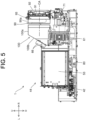
FIG. 5 is a cross-sectional view illustrating the configuration of the interior of the engine room. -
FIG. 6 is an enlarged perspective view illustrating a configuration of a main portion of the interior of the engine room. -
FIG. 7 is a perspective view of an air guide portion provided in the hydraulic excavator. -
FIG. 8 is a perspective view of the air guide portion. -
FIG. 9 is a perspective view of the air guide portion. - The following is a description of an embodiment of the present invention based on the drawings.
-
FIG. 1 is a side view illustrating a schematic configuration of a hydraulic excavator (electric excavator) 1 provided as an example of an electric work machine according to the present embodiment. Thehydraulic excavator 1 includes alower traveling body 2, a work instrument 3, and an upperswivel body 4. In the present embodiment, thehydraulic excavator 1 or the upper swivel body 4 (particularly, an engine room 44) is also referred to as a "machine body". - Here, directions are defined as follows. A forward direction is a direction in which an operator (manipulator, driver) seated on a driver's
seat 41a of the upperswivel body 4 faces front, and a backward direction is a direction opposite to the forward direction. Therefore, in a state where the upperswivel body 4 does not swivel with respect to the lower traveling body 2 (0-degree swivel angle), a front-back direction of the upperswivel body 4 coincides with a direction in which the lowertraveling body 2 moves forward and backward. As viewed from the operator seated on the driver'sseat 41a, a left side is defined as "left" and a right side is defined as "right". A gravity direction perpendicular to the front-back direction and a left-right direction is defined as an up-down direction, in which an upstream side of the gravity direction is defined as "up", and a downstream side thereof is defined as "down". In the drawings, thehydraulic excavator 1 is illustrated in a state where the upperswivel body 4 does not swivel with respect to thelower traveling body 2. In addition, in the drawings, if necessary, forward is denoted by a symbol "F", likewise, backward by "B", rightward by "R", leftward by "L", upward by "U", and downward by "D". - The lower
traveling body 2 is provided with a pair of left andright crawlers 21 and a pair of left andright traveling motors 22. Each of thetraveling motors 22 is a hydraulic motor. The left and right travelingmotors 22 drive the left andright crawlers 21, respectively, thereby allowing thehydraulic excavator 1 to move forward and backward. The lower travelingbody 2 is provided with ablade 23 for performing a ground leveling work and ablade cylinder 23a. Theblade cylinder 23a is a hydraulic cylinder to rotate theblade 23 in the up-down direction. - The work instrument 3 has a
boom 31, anarm 32, and abucket 33. Theboom 31, thearm 32, and thebucket 33 are independently driven, thereby to make it possible to perform excavation work of earth, sand, and the like. - The
boom 31 is rotated by aboom cylinder 31a. Theboom cylinder 31a has a base end portion thereof supported by a front part of the upperswivel body 4, and is movable freely in an extendable and retractable manner. Thearm 32 is rotated by anarm cylinder 32a. Thearm cylinder 32a has a base end portion thereof supported by theboom 31, and is movable freely in an extendable and retractable manner. Thebucket 33 is rotated by abucket cylinder 33a. Thebucket cylinder 33a has a base end portion thereof supported by thearm 32, and is movable freely in an extendable and retractable manner. Theboom cylinder 31a, thearm cylinder 32a, and thebucket cylinder 33a each include a hydraulic cylinder. - The upper
swivel body 4 is positioned above the lower travelingbody 2, and is so provided as to be swivelable via a swivel bearing (not illustrated) relative to thelower traveling body 2. In the upperswivel body 4, asteering part 41, aswivel frame 42, aswivel motor 43, theengine room 44 and the like are arranged. By driving of theswivel motor 43 that is a hydraulic motor, the upperswivel body 4 swivels via a swivel bearing. - A hydraulic pump 71 (see
FIG. 2 ) is arranged in the upperswivel body 4. Thehydraulic pump 71 is driven by an electric motor 61 (seeFIG. 2 ) inside theengine room 44. Thehydraulic pump 71 supplies a hydraulic oil (pressure oil) to hydraulic motors (for example, the left andright traveling motors 22 and the swivel motor 43), and hydraulic cylinders (for example, theblade cylinder 23a, theboom cylinder 31a, thearm cylinder 32a, and thebucket cylinder 33a). The hydraulic motors and the hydraulic cylinders that are driven with the hydraulic oil supplied from thehydraulic pump 71 are collectively referred to as hydraulic actuators 73 (seeFIG. 2 ). - The driver's
seat 41a is arranged in thesteering part 41.Various levers 41b are arranged around the driver'sseat 41a. The operator is seated on the driver'sseat 41a and operates thelevers 41b, thereby driving thehydraulic actuators 73. As a result, traveling of the lower travelingbody 2, the ground leveling work by theblade 23, the excavating work by the work instrument 3, the swiveling of the upperswivel body 4 and the like can be performed. - A
battery unit 53 is arranged in theupper swivel body 4. Thebattery unit 53 is composed of, for example, a lithium-ion battery unit, and stores electric power for driving theelectric motor 61. Thebattery unit 53 may be composed of a plurality of batteries as a unit or may be composed of a single battery cell. Theupper swivel body 4 has a power feed port which is not illustrated. The power feed port and acommercial power source 51, which is an external power source, are connected via apower feed cable 52. This allows charging of thebattery unit 53. - The
upper swivel body 4 is further provided with alead battery 54. Thelead battery 54 outputs a low-voltage (12 V, for example) DC voltage. The output from thelead battery 54 is supplied as a control voltage to, for example, a system controller 67 (seeFIG. 2 ), a drive unit of a fan 91 (seeFIG. 6 ), and the like. - The
hydraulic excavator 1 may be so configured as to be a combination of hydraulic devices such as thehydraulic actuators 73 and actuators driven by electric power. As the actuators driven by electric power, for example, an electric traveling motor, an electric cylinder, and an electric swivel motor are included. -
FIG. 2 is a block diagram schematically illustrating the configuration of electric and hydraulic systems of thehydraulic excavator 1. Thehydraulic excavator 1 includes theelectric motor 61, acharger 62, aninverter 63, a power drive unit (PDU) 64, ajunction box 65, a DC-DC converter 66, and thesystem controller 67. - Electric devices EL include the
electric motor 61, thecharger 62, theinverter 63, thePDU 64, thejunction box 65, the DC-DC converter 66, thebattery unit 53, and thelead battery 54. That is, thehydraulic excavator 1 includes a plurality of the electric devices EL. The plurality of electric devices EL include a water-cooled electric device EL-W and an air-cooled electric device EL-A, details of which are described below. Thesystem controller 67 is composed of an electronic control unit (ECU) for electrically controlling individual parts of thehydraulic excavator 1. - The
electric motor 61 is driven by electric power supplied from thebattery unit 53 via thejunction box 65 and theinverter 63. Theelectric motor 61 includes a permanent magnet motor or an induction motor. Theelectric motor 61 is arranged on theswivel frame 42. - The charger 62 (also referred to as a power feeder) converts an AC voltage supplied from the
commercial power source 51, illustrated inFIG. 1 , via thepower feed cable 52 into a DC voltage. Theinverter 63 converts a DC voltage supplied from thebattery unit 53 into an AC voltage and supplies the AC voltage to theelectric motor 61. Thus, theelectric motor 61 is rotated. The AC voltage (current) is supplied from theinverter 63 to theelectric motor 61 based on a rotation command output from thesystem controller 67. - The
PDU 64 is a battery control unit that controls an internal battery relay to control inputting and outputting of thebattery unit 53. Thejunction box 65 is so configured as to include a charger relay, an inverter relay, a fuse and the like. The voltage output from the above-mentionedcharger 62 is supplied to thebattery unit 53 via thejunction box 65 and thePDU 64. Further, the voltage output from thebattery unit 53 is supplied via thePDU 64 and thejunction box 65 to theinverter 63. - The DC-
DC converter 66 lowers a high-voltage (300 V, for example) DC voltage supplied from thebattery unit 53 via thejunction box 65 to a low voltage (12 V, for example). Like the output from thelead battery 54, the voltage output from the DC-DC converter 66 is supplied to thesystem controller 67, the drive unit of thefan 91, etc. - A plurality of the
hydraulic pumps 71 is connected to a rotation axis (output shaft) of theelectric motor 61. The plurality ofhydraulic pumps 71 include a variable displacement pump and a fixed displacement pump.FIG. 2 illustrates only onehydraulic pump 71 as an example. Eachhydraulic pump 71 is connected to ahydraulic oil tank 74 that contains (stores) hydraulic oil. When thehydraulic pump 71 is driven by theelectric motor 61, the hydraulic oil in thehydraulic oil tank 74 is supplied to thehydraulic actuator 73 via acontrol valve 72. Thus, thehydraulic actuator 73 is driven. Thecontrol valve 72 is a direction switch valve that controls a flow direction and a flow rate of the hydraulic oil supplied to thehydraulic actuator 73. As described above, thehydraulic excavator 1 includes thehydraulic pump 71 that is driven by any one of the plurality of electric devices EL (for example, the electric motor 61) and discharges the hydraulic oil. -
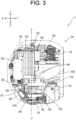
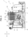
FIGS. 3 and4 are a plan view and a right side view, respectively, illustrating the configuration of the interior of theengine room 44 of thehydraulic excavator 1.FIG. 5 is a cross-sectional view of the interior of theengine room 44 illustrated inFIG. 3 taken along the line A-A ' in the up-down direction.FIG. 6 is an enlarged perspective view illustrating a configuration of a main portion of the interior of theengine room 44. InFIGS. 3 and6 , anupper surface 90a of a housing 90 (seeFIGS. 4 and5 ) and anupper surface 100a of an air guide portion 100 (seeFIG. 5 ) are not illustrated for a purpose of clarifying a configuration of an interior of thehousing 90 and theair guide portion 100. - As illustrated in
FIG. 3 , in the present embodiment, fourbattery units 53 are arranged side by side in the front-back direction on theswivel frame 42 via a vibration-proofing member 80 (seeFIG. 5 ) and the like. Thebattery unit 53 located at the most backward position is positioned at a center in the right-left direction on theswivel frame 42. The remaining threebattery units 53 are arranged in such a manner to be shifted in the left direction with respect to thebattery unit 53 located at the most backward position. Thus, the plurality ofbattery units 53 are efficiently arranged in a limited narrow space near a rear end edge of theswivel frame 42 formed in a semicircular shape in a plan view. The number and arrangement of thebattery units 53 are not limited to the example of the present embodiment. - As illustrated in
FIG. 5 , theelectric motor 61, thehydraulic pump 71, and the like are arranged on a right side of the plurality ofbattery units 53 on theswivel frame 42. Hereinafter, the configuration of the interior of theengine room 44 will be described in detail. - As illustrated in
FIG. 6 , thehydraulic excavator 1 includes thefan 91. Thefan 91 is rotatably supported inside thehousing 90 and takes outside air into an interior of the machine body by rotation. That is, thefan 91 of the present embodiment is of a suction type. Thehousing 90 has a frame shape, and both ends in the left-right direction are open. A rotation axis CA of thefan 91 extends in the left-right direction. Thehydraulic pump 71 is located below the fan 91 (housing 90). Thehydraulic pump 71 is connected to thehydraulic oil tank 74 via a hydraulic hose H (seeFIG. 4 ). - The
air guide portion 100 is arranged on a left side of thehousing 90, that is, between thehousing 90 and the battery units 53 (in particular, thebattery unit 53 located at the most forward position). Theair guide portion 100 will be described in detail below. The electric devices EL such as theinverter 63 and the DC-DC converter 66 described above are attached to the air guide portion 100 (particularly, a secondflow path portion 120 described below). - As illustrated in
FIGS. 3 and4 , thecharger 62 is arranged on a back side of the fan 91 (housing 90) and thehydraulic pump 71. - The
hydraulic excavator 1 further includes aradiator 92 and anoil cooler 93. Theradiator 92 is a first heat exchanger that cools a refrigerant passing through at least one of the plurality of electric devices EL (for example, the battery unit 53) illustrated inFIG. 3 and the like. Thebattery unit 53 can be cooled (water-cooled) by cooling the refrigerant through heat exchange at theradiator 92 and supplying the refrigerant from theradiator 92 to thebattery unit 53. The refrigerant is, for example, cooling water. - The
oil cooler 93 is a second heat exchanger connected with an oil path circulating via thehydraulic pump 71 and the hydraulic actuator 73 (seeFIG. 2 ), etc. Theoil cooler 93 cools, through heat exchange, the hydraulic oil flowing in the oil path by driving of thehydraulic pump 71. - As illustrated in
FIG. 6 , theradiator 92 is positioned on a right side of thefan 91. That is, theradiator 92 is positioned on an outer side of machine body than thefan 91 in the left-right direction. Since thefan 91 is of a suction type as described above, when thefan 91 is rotated, outside air is sucked into the interior of the machine body from an outside of the machine body. The outside air flows from the right side toward the left side in the interior of the machine body. That is, the outside air flows from theradiator 92 toward thefan 91. From this, it can be said that theradiator 92 is arranged, on an upstream side of thefan 91 in a flow direction of the outside air flown by thefan 91. - On the other hand, the
oil cooler 93 is positioned on a left side of thefan 91. That is, theoil cooler 93 is positioned on an inner side of the machine body with respect to thefan 91 in the left-right direction. Therefore, when thefan 91 is rotated, the outside air sucked into the interior of the machine body from the outside of the machine body flows from the right side (radiator 92 side) to the left side (oil cooler 93 side) via thefan 91. Thus, it can be said that theoil cooler 93 is arranged, with respect to thefan 91, on a downstream side in the flow direction of the outside air. - In this way, the
radiator 92 and theoil cooler 93 are arranged, with respect to thefan 91, on sides opposite to each other in the left-right direction. Thus, by driving of asingle fan 91, the outside air taken into the interior of the machine body from the outside of the machine body hits theradiator 92 and theoil cooler 93 in this order, and both theradiator 92 and theoil cooler 93 can be cooled. Thus, as compared with a configuration in which cooling fans are provided corresponding to theradiator 92 and theoil cooler 93, respectively, a compact layout advantageous for the small-sizedhydraulic excavator 1 can be realized. In other words, both theradiator 92 and theoil cooler 93 can be cooled in a compact layout. - In addition, since the outside air hit the
radiator 92 can also be hit theoil cooler 93, it can be said that the outside air used for cooling theradiator 92 can be effectively used for cooling theoil cooler 93. Further, since theradiator 92 is arranged on the upstream side in the flow direction of the outside air flown by thefan 91, it is possible to prevent a hand of a person (for example, a maintenance person) as well as foreign matter such as earth and sand from accidentally entering thefan 91 from the outside of the machine body by theradiator 92. Accordingly, it is possible to easily prevent entry of the foreign matter or the like without installing a dedicated member (for example, a mesh-like fence) that blocks the entry of foreign matter or the like. - In the present embodiment, as illustrated in
FIGS. 3 and6 , theoil cooler 93 is arranged to face a part of the fan 91 (in a stationary state). That is, in the front-back direction, a length of occupation (width) of theoil cooler 93 is shorter than a length of occupation (width) of thefan 91. Since thefan 91 is of a suction type as described above, when thefan 91 is rotated, a part of the outside air taken into the interior of the machine body flows toward theoil cooler 93, and the rest flows off theoil cooler 93. The high-temperature oil cooler 93 is cooled by the outside air flowing from thefan 91 toward theoil cooler 93. On the other hand, the outside air flowing off the oil cooler 93 from thefan 91 does not hit the high-temperature oil cooler 93, and thus has a relatively low temperature compared to the outside air hitting the oil cooler 93 (the outside air used for cooling the oil cooler 93). From a viewpoint of effectively using the outside air having a relatively low temperature for cooling the electric device EL (for example, the electric motor 61), it is desirable that theoil cooler 93 is arranged to face a part of thefan 91 as in the present embodiment. - Next, details of the
air guide portion 100 provided in theengine room 44 will be described.FIGS. 7 to 9 are perspective views of theair guide portion 100 as viewed from different directions. - The
air guide portion 100 has a firstflow path portion 110 and a secondflow path portion 120. That is, thehydraulic excavator 1 has the firstflow path portion 110 and the secondflow path portion 120. The firstflow path portion 110 and the secondflow path portion 120 are partitioned by apartition plate 130. In other words, the firstflow path portion 110 and the secondflow path portion 120 share thepartition plate 130. - As illustrated in
FIG. 6 , theair guide portion 100 is arranged on the left side with respect to thehousing 90 having thefan 91 and the like, that is, on the inner side of the machine body. Therefore, the outside air that has passed through the interior of thehousing 90 by thefan 91 passes through an exit-side opening portion 90b of thehousing 90, is guided to theair guide portion 100, and flows through an interior of any one of the firstflow path portion 110 and the secondflow path portion 120 of theair guide portion 100. - The first
flow path portion 110 has afirst opening portion 111 at an upstream end portion in the flow direction of the outside air and asecond opening portion 112 at a downstream end portion in the flow direction of the outside air. That is, the firstflow path portion 110 has thefirst opening portion 111 at one end portion and thesecond opening portion 112 at the other end portion. Thefirst opening portion 111 is positioned on a side opposite to theoil cooler 93 with respect to the exit-side opening portion 90b of thehousing 90, and opens toward the right side in the left-right direction. In the firstflow path portion 110, the flow path is bent from the left-right direction to the front-back direction by thepartition plate 130. As a result, thesecond opening portion 112 of the firstflow path portion 110 opens toward the front in the front-back direction (seeFIGS. 6 ,8 , and9 ). The shape of firstflow path portion 110 is not limited to the bent shape described above. - In this configuration, by the
fan 91, the outside air flowing toward theoil cooler 93 in thehousing 90 hits theoil cooler 93 to cool theoil cooler 93, and then becomes a relatively high-temperature wind to flow into an interior of the firstflow path portion 110 via thefirst opening portion 111. Then, the relatively high-temperature wind flowing through the interior of the firstflow path portion 110 is discharged through thesecond opening portion 112. Therefore, in view of smoothly discharging the relatively high-temperature air after cooling theoil cooler 93 to the outside of the machine body via thesecond opening portion 112, as illustrated inFIG. 6 , it is desirable that thefirst opening portion 111 be positioned on a side opposite to thefan 91 with respect to theoil cooler 93. - The second
flow path portion 120 has athird opening portion 121 at the upstream end portion in the flow direction of the outside air and afourth opening portion 122 at the downstream end portion in the flow direction of the outside air. That is, the secondflow path portion 120 has thethird opening portion 121 at one end portion and thefourth opening portion 122 at the other end portion. Thethird opening portion 121 is positioned on a side opposite to thefan 91 with respect to the exit-side opening portion 90b of thehousing 90, and opens toward the right side in the left-right direction. In the secondflow path portion 120, the flow path is bent from the right-left direction to the up-down direction by aninclined surface 100b which is inclined downward from a left end portion of theupper surface 100a toward the inner side of the machine body (the left side in the right-left direction). As a result, thefourth opening portion 122 of the secondflow path portion 120 opens downward. The shape of secondflow path portion 120 is not limited to the bent shape described above. - In addition, the
third opening portion 121 of the secondflow path portion 120 is positioned side by side with thefirst opening portion 111 of the first flow path portion 110 (in the F-B direction inFIG. 7 and the like) when viewed from the direction of the rotation axis CA of thefan 91, and is connected to thefirst opening portion 111. Accordingly, one large opening portion is formed on thehousing 90 side of theair guide portion 100. Further, as illustrated inFIG. 6 , thethird opening portion 121 is positioned so as to be shifted from the oil cooler 93 (in the F-B direction) when viewed from the direction of the rotation axis CA of thefan 91. Therefore, thethird opening portion 121 does not overlap with theoil cooler 93 when viewed from the direction of the rotation axis CA of thefan 91. - With this configuration, out of the outside air taken into the interior of the
housing 90 via theradiator 92 by thefan 91, the outside air flowing off theoil cooler 93 is guided into an interior of the secondflow path portion 120 via thethird opening portion 121. Then, the outside air flowing through the interior of the secondflow path portion 120 is discharged from thefourth opening portion 122. Since the outside air flowing off theoil cooler 93 does not hit the high-temperature oil cooler 93, the outside air has a relatively low temperature compared to the outside air hitting the oil cooler 93 (the outside air used for cooling the oil cooler 93). From a viewpoint of effectively using the outside air having a relatively low temperature for cooling the electric device EL (for example, the electric motor 61), it is desirable that thethird opening portion 121 serving as an inlet for guiding the outside air having a relatively low temperature to the interior of the secondflow path portion 120 is positioned to be shifted from theoil cooler 93 when viewed from the direction of the rotation axis CA of thefan 91 as in the present embodiment. - As illustrated in
FIG. 2 , the plurality of electric devices EL included in thehydraulic excavator 1 include the water-cooled device EL-W through which the above-described refrigerant passes and the air-cooled device EL-A. The water-cooled device EL-W is, for example, thebattery unit 53. That is, the plurality of electric devices EL include thebattery unit 53 through which the refrigerant passes. - The air-cooled devices EL-A include, for example, the
electric motor 61, thecharger 62, theinverter 63, thePDU 64, thejunction box 65, the DC-DC converter 66, and thelead battery 54. That is, the plurality of air-cooled devices EL-A include theelectric motor 61 that drives thehydraulic pump 71. - The air-cooled device EL-A can be efficiently cooled (air-cooled) if the air-cooled device EL-A can be directly hit by a relatively low-temperature wind that flows off the oil cooler 93 (through the outside of the oil cooler 93) after cooling the
radiator 92 by thefan 91, enters the interior of the secondflow path portion 120 from thethird opening portion 121, and is discharged from thefourth opening portion 122. Therefore, from the viewpoint of improving the cooling efficiency of the air-cooled device EL-A, it is desirable that any one of the plurality of air-cooled devices EL-A is arranged at thefourth opening portion 122 of the secondflow path portion 120. - In the present embodiment, the
electric motor 61, which is the air-cooled device EL-A, is arranged at thefourth opening portion 122. In this case, since the relatively low-temperature wind discharged from thefourth opening portion 122 directly hits theelectric motor 61, the cooling efficiency of theelectric motor 61 is improved. - In addition, from the viewpoint of realizing a compact layout by fitting the air-cooled device EL-A (for example, the electric motor 61) from downward to the
fourth opening portion 122 of the secondflow path portion 120, it is desirable that thefourth opening portion 122 opens downward as in the present embodiment. - From the viewpoint of efficiently cooling the other air-cooled devices EL-A (other than the electric motor 61) by the relatively low-temperature wind flowing through the interior of the second
flow path portion 120, it is desirable that any another one of the plurality of air-cooled devices EL-A is arranged on awall surface 120W (seeFIGS. 7 and9 ) of the secondflow path portion 120. - In the present embodiment, the
inverter 63 is arranged on a side surface 120W1 (seeFIG. 7 ) on the back side in the front-back direction of the secondflow path portion 120. The DC-DC converter 66 is arranged on a back surface 120W2 (seeFIG. 9 ), which constitutes the secondflow path portion 120, of theinclined surface 100b of theair guide portion 100. In this case, the relatively low-temperature wind flows through the interior of the secondflow path portion 120, whereby theinverter 63, which is the air-cooled device EL-A arranged on the side surface 120W1, is efficiently cooled, and the DC-DC converter 66, which is the air-cooled device EL-A arranged on the back surface 120W2, is efficiently cooled. - The air-cooled devices EL-A arranged on the
wall surface 120W of the secondflow path portion 120 may include a heat dissipation portion such as fins. In addition, the heat dissipation portion may be positioned protruding into the interior of the secondflow path portion 120. In this case, the relatively low-temperature wind flowing through the interior of the secondflow path portion 120 hits the heat dissipation portion, thereby further improving the cooling efficiency of the air-cooled device EL-A arranged on thewall surface 120W. - From the viewpoint of cooling the other air-cooled devices EL-A by using the relatively low-temperature wind discharged from the
fourth opening portion 122 of the secondflow path portion 120, any another one of the plurality of air-cooled devices EL-A may be arranged outside the secondflow path portion 120. - In the present embodiment, as illustrated in
FIG. 3 , other air-cooled devices EL-A such as thecharger 62 and thejunction box 65 are arranged outside the secondflow path portion 120. In this case, the relatively low-temperature wind discharged from thefourth opening portion 122 of the secondflow path portion 120 hits thecharger 62 and the like around the secondflow path portion 120, thereby cooling thecharger 62 and the like. That is, the relatively low-temperature wind discharged from thefourth opening portion 122 is effectively used to cool thecharger 62 and the like. - From the viewpoint of effectively utilizing a narrow (limited) space in the
engine room 44 while individually cooling theelectric motor 61, which is the air-cooled device EL-A, and thebattery unit 53, which is the water-cooled device EL-W, it is desirable that theelectric motor 61 be arranged near the water-cooled device EL-W in theengine room 44. In this regard, it is desirable that theelectric motor 61 be arranged side by side with the water-cooled device EL-W. - In addition, from the viewpoint of effectively utilizing the narrow (limited) space in the
engine room 44 while separately cooling the water-cooled device EL-W and the plurality of air-cooled devices EL-A, it is desirable that thebattery unit 53 which is the water-cooled device EL-W be arranged near the second flow path portion 120 (in which the plurality of air-cooled devices EL-A are arranged on thewall surface 120W) in theengine room 44. In this regard, as illustrated inFIG. 5 , it is desirable that thebattery unit 53 is arranged side by side with the secondflow path portion 120. - In the present embodiment, as illustrated in
FIG. 6 , the example in which theoil cooler 93 is arranged so as to overlap a part of theradiator 92 when viewed from the direction of the rotation axis CA of thefan 91 has been described, but theoil cooler 93 may be arranged so as not to overlap theradiator 92. For example, as viewed from the direction of the rotation axis CA, theradiator 92 may be arranged so as to overlap with the left half of thefan 91, and theoil cooler 93 may be arranged so as to overlap with the right half of thefan 91. Even in this case, there is no change in the fact that both theradiator 92 and theoil cooler 93 can be cooled by the driving of thesingle fan 91, and theradiator 92 and theoil cooler 93 can be cooled in a compact layout. - The
hydraulic excavator 1 which is the construction machine has been described heretofore as the example of the electric work machine, but the electric work machine is not limited to thehydraulic excavator 1 and may be any other construction machine such as a wheel loader. The electric work machine may be an agricultural machine such as a combine harvester or a tractor. - The
hydraulic excavator 1 described in the present embodiment can also be referred to as an electric work machine as illustrated in the following Supplementary Notes. - An electric work machine of Supplementary Note (1) comprising:
- a plurality of electric devices;
- a first heat exchanger that cools a refrigerant passing through at least one of the plurality of electric devices;
- a hydraulic pump that is driven by any one of the plurality of electric devices and discharges hydraulic oil;
- a second heat exchanger that cools the hydraulic oil; and
- a fan that takes outside air into an interior of a machine body, wherein
- the first heat exchanger is arranged on an upstream side of the fan in a flow direction of the outside air flown by the fan, and
- the second heat exchanger is arranged on a downstream side of the fan in the flow direction of the outside air.
- The electric work machine of Supplementary Note (2) is the electric work machine according to Supplementary Note (1), wherein the second heat exchanger is arranged to face a part of the fan.
- The electric work machine of Supplementary Note (3) is the electric work machine according to Supplementary Note (2), further comprising:
- a first flow path portion that has a first opening portion at one end portion and a second opening portion at another end portion,
- wherein the first opening portion of the first flow path portion is positioned on a side opposite to the fan with respect to the second heat exchanger.
- The electric work machine of Supplementary Note (4) is the electric work machine according to Supplementary Note (3), further comprising:
- a second flow path portion that has a third opening portion at one end portion and a fourth opening portion at another end portion,
- wherein, when viewed from a rotation axis direction of the fan, the third opening portion of the second flow path portion is positioned side by side with the first opening portion of the first flow path portion and is positioned to be shifted from the second heat exchanger.
- The electric work machine of Supplementary Note (5) is the electric work machine according to Supplementary Note (4), wherein
- the plurality of electric devices include a water-cooled device through which the refrigerant passes and a plurality of air-cooled devices, and
- any one of the plurality of air-cooled devices is arranged at the fourth opening portion of the second flow path portion.
- The electric work machine of Supplementary Note (6) is the electric work machine according to Supplementary Note (5), wherein any another one of the plurality of air-cooled devices is arranged on a wall surface of the second flow path portion.
- The electric work machine of Supplementary Note (7) is the electric work machine according to Supplementary Note (5) or Note (6),
wherein any another one of the plurality of air-cooled devices is arranged outside the second flow path portion. - The electric work machine of Supplementary Note (8) is the electric work machine according to any one of Supplementary Notes (5) to (7),
wherein the fourth opening portion opens downward. - The electric work machine of Supplementary Note (9) is the electric work machine according to any one of Supplementary Notes (5) to (8), wherein
- the plurality of air-cooled devices include an electric motor that drives the hydraulic pump, and
- the electric motor is arranged side by side with the water-cooled device.
- The electric work machine of Supplementary Note (10) is the electric work machine according to any one of Supplementary Notes (4) to (9), wherein
- the plurality of electric devices include a battery unit through which the refrigerant passes, and
- the battery unit is arranged side by side with the second flow path portion.
- The embodiments of the present invention have been described above, but the scope of the present invention is not limited thereto, and can be carried out within an extended or modified range without departing from the gist of the present invention.
- The present invention is applicable to a work machine such as a construction machine and an agricultural machine, for example.
-
- 1 Hydraulic excavator (electric work machine)
- 44 Engine room (machine body)
- 53 Battery unit (electric device, water-cooled device)
- 54 Lead battery (electric device, air-cooled device)
- 61 Electric motor (electric device, air-cooled device)
- 62 Charger (electric device, air-cooled device)
- 63 Inverter (electric device, air-cooled device)
- 65 Junction box (electric device, air-cooled device)
- 66 DC-DC converter (electric device, air-cooled device)
- 71 Hydraulic pump
- 91 Fan
- 92 Radiator (first heat exchanger)
- 93 Oil cooler (second heat exchanger)
- 110 First flow path portion
- 111 First opening portion
- 112 Second opening portion
- 120 Second flow path portion
- 120W Wall Surface
- 120W1 Side surface (wall surface)
- 120W2 Back surface (wall surface)
- 121 Third opening portion
- 122 Fourth opening portion
- CA Rotation axis
- EL Electric device
- EL-W Water-cooled device
- EL-A Air-cooled device
Claims (10)
- An electric work machine comprising:a plurality of electric devices;a first heat exchanger that cools a refrigerant passing through at least one of the plurality of electric devices;a hydraulic pump that is driven by any one of the plurality of electric devices and discharges hydraulic oil;a second heat exchanger that cools the hydraulic oil; anda fan that takes outside air into an interior of a machine body, whereinthe first heat exchanger is arranged on an upstream side of the fan in a flow direction of the outside air flown by the fan, andthe second heat exchanger is arranged on a downstream side of the fan in the flow direction of the outside air.
- The electric work machine according to claim 1, wherein the second heat exchanger is arranged to face a part of the fan.
- The electric work machine according to claim 2, further comprising:a first flow path portion that has a first opening portion at one end portion and a second opening portion at another end portion,wherein the first opening portion of the first flow path portion is positioned on a side opposite to the fan with respect to the second heat exchanger.
- The electric work machine according to claim 3, further comprising:a second flow path portion that has a third opening portion at one end portion and a fourth opening portion at another end portion,wherein, when viewed from a rotation axis direction of the fan, the third opening portion of the second flow path portion is positioned side by side with the first opening portion of the first flow path portion and is positioned to be shifted from the second heat exchanger.
- The electric work machine according to claim 4, whereinthe plurality of electric devices include a water-cooled device through which the refrigerant passes and a plurality of air-cooled devices, andany one of the plurality of air-cooled devices is arranged at the fourth opening portion of the second flow path portion.
- The electric work machine according to claim 5, wherein any another one of the plurality of air-cooled devices is arranged on a wall surface of the second flow path portion.
- The electric work machine according to claim 5, wherein any another one of the plurality of air-cooled devices is arranged outside the second flow path portion.
- The electric work machine according to claim 5, wherein the fourth opening portion opens downward.
- The electric work machine according to claim 5, whereinthe plurality of air-cooled devices include an electric motor that drives the hydraulic pump, andthe electric motor is arranged side by side with the water-cooled device.
- The electric work machine according to any one of claims 4 to 9, whereinthe plurality of electric devices include a battery unit through which the refrigerant passes, andthe battery unit is arranged side by side with the second flow path portion.
Applications Claiming Priority (1)
| Application Number | Priority Date | Filing Date | Title |
|---|---|---|---|
| JP2022191003A JP7848104B2 (en) | 2022-11-30 | 2022-11-30 | electric work machine |
Publications (2)
| Publication Number | Publication Date |
|---|---|
| EP4397814A1 true EP4397814A1 (en) | 2024-07-10 |
| EP4397814B1 EP4397814B1 (en) | 2025-07-16 |
Family
ID=88833937
Family Applications (1)
| Application Number | Title | Priority Date | Filing Date |
|---|---|---|---|
| EP23209618.0A Active EP4397814B1 (en) | 2022-11-30 | 2023-11-14 | Electric work machine |
Country Status (5)
| Country | Link |
|---|---|
| US (1) | US12529207B2 (en) |
| EP (1) | EP4397814B1 (en) |
| JP (1) | JP7848104B2 (en) |
| KR (1) | KR20240081337A (en) |
| CN (1) | CN118110218A (en) |
Citations (4)
| Publication number | Priority date | Publication date | Assignee | Title |
|---|---|---|---|---|
| JPH11140906A (en) * | 1997-11-11 | 1999-05-25 | Yutani Heavy Ind Ltd | Battery-powder hydraulic shovel |
| JP5824480B2 (en) * | 2013-06-07 | 2015-11-25 | ヤンマー株式会社 | Electric backhoe |
| WO2020054091A1 (en) * | 2018-09-14 | 2020-03-19 | 株式会社小松製作所 | Electric construction machine |
| JP2021080708A (en) | 2019-11-18 | 2021-05-27 | 株式会社クボタ | Revolving work machine |
Family Cites Families (7)
| Publication number | Priority date | Publication date | Assignee | Title |
|---|---|---|---|---|
| JP4547811B2 (en) | 2000-10-03 | 2010-09-22 | 株式会社デンソー | Vehicle cooling system |
| JP2004169518A (en) | 2002-11-22 | 2004-06-17 | Komatsu Ltd | Cooling equipment for construction machinery |
| KR100974278B1 (en) * | 2008-03-18 | 2010-08-06 | 볼보 컨스트럭션 이키프먼트 홀딩 스웨덴 에이비 | Engine room of construction equipment |
| US11565210B2 (en) * | 2017-10-27 | 2023-01-31 | Deere & Company | Method of cleaning an air inlet screen of a work vehicle |
| US10982586B2 (en) * | 2019-02-05 | 2021-04-20 | Caterpillar Inc. | Distributed cooling system for a work machine |
| JP7323349B2 (en) | 2019-06-24 | 2023-08-08 | 株式会社クボタ | electric work vehicle |
| KR102654846B1 (en) | 2019-08-19 | 2024-04-05 | 현대자동차주식회사 | Cooling module for vehicle |
-
2022
- 2022-11-30 JP JP2022191003A patent/JP7848104B2/en active Active
-
2023
- 2023-10-31 KR KR1020230147372A patent/KR20240081337A/en active Pending
- 2023-11-05 US US18/387,036 patent/US12529207B2/en active Active
- 2023-11-14 EP EP23209618.0A patent/EP4397814B1/en active Active
- 2023-11-28 CN CN202311601251.0A patent/CN118110218A/en active Pending
Patent Citations (4)
| Publication number | Priority date | Publication date | Assignee | Title |
|---|---|---|---|---|
| JPH11140906A (en) * | 1997-11-11 | 1999-05-25 | Yutani Heavy Ind Ltd | Battery-powder hydraulic shovel |
| JP5824480B2 (en) * | 2013-06-07 | 2015-11-25 | ヤンマー株式会社 | Electric backhoe |
| WO2020054091A1 (en) * | 2018-09-14 | 2020-03-19 | 株式会社小松製作所 | Electric construction machine |
| JP2021080708A (en) | 2019-11-18 | 2021-05-27 | 株式会社クボタ | Revolving work machine |
Also Published As
| Publication number | Publication date |
|---|---|
| JP7848104B2 (en) | 2026-04-20 |
| JP2024078568A (en) | 2024-06-11 |
| KR20240081337A (en) | 2024-06-07 |
| US20240175238A1 (en) | 2024-05-30 |
| EP4397814B1 (en) | 2025-07-16 |
| US12529207B2 (en) | 2026-01-20 |
| CN118110218A (en) | 2024-05-31 |
Similar Documents
| Publication | Publication Date | Title |
|---|---|---|
| EP4306723A1 (en) | Electric work machine | |
| EP4170098B1 (en) | Electric work machine techinical field | |
| EP4306724A1 (en) | Electric work machine | |
| EP4299839A1 (en) | Electric work machine | |
| US20230417019A1 (en) | Electric work machine | |
| US12618224B2 (en) | Electric work machine | |
| EP4397814B1 (en) | Electric work machine | |
| JP2024004139A (en) | electric work machine | |
| EP4481122B1 (en) | Electric work machine | |
| EP4726111A1 (en) | Work machine | |
| EP4726110A1 (en) | Work machine | |
| JP2024004141A (en) | electric work machine | |
| CN120331324A (en) | Electric working machinery |
Legal Events
| Date | Code | Title | Description |
|---|---|---|---|
| PUAI | Public reference made under article 153(3) epc to a published international application that has entered the european phase |
Free format text: ORIGINAL CODE: 0009012 |
|
| STAA | Information on the status of an ep patent application or granted ep patent |
Free format text: STATUS: THE APPLICATION HAS BEEN PUBLISHED |
|
| AK | Designated contracting states |
Kind code of ref document: A1 Designated state(s): AL AT BE BG CH CY CZ DE DK EE ES FI FR GB GR HR HU IE IS IT LI LT LU LV MC ME MK MT NL NO PL PT RO RS SE SI SK SM TR |
|
| STAA | Information on the status of an ep patent application or granted ep patent |
Free format text: STATUS: REQUEST FOR EXAMINATION WAS MADE |
|
| 17P | Request for examination filed |
Effective date: 20250102 |
|
| GRAP | Despatch of communication of intention to grant a patent |
Free format text: ORIGINAL CODE: EPIDOSNIGR1 |
|
| STAA | Information on the status of an ep patent application or granted ep patent |
Free format text: STATUS: GRANT OF PATENT IS INTENDED |
|
| INTG | Intention to grant announced |
Effective date: 20250214 |
|
| GRAS | Grant fee paid |
Free format text: ORIGINAL CODE: EPIDOSNIGR3 |
|
| GRAA | (expected) grant |
Free format text: ORIGINAL CODE: 0009210 |
|
| STAA | Information on the status of an ep patent application or granted ep patent |
Free format text: STATUS: THE PATENT HAS BEEN GRANTED |
|
| AK | Designated contracting states |
Kind code of ref document: B1 Designated state(s): AL AT BE BG CH CY CZ DE DK EE ES FI FR GB GR HR HU IE IS IT LI LT LU LV MC ME MK MT NL NO PL PT RO RS SE SI SK SM TR |
|
| REG | Reference to a national code |
Ref country code: GB Ref legal event code: FG4D |
|
| REG | Reference to a national code |
Ref country code: CH Ref legal event code: EP |
|
| REG | Reference to a national code |
Ref country code: DE Ref legal event code: R096 Ref document number: 602023004864 Country of ref document: DE |
|
| REG | Reference to a national code |
Ref country code: IE Ref legal event code: FG4D |
|
| REG | Reference to a national code |
Ref country code: NL Ref legal event code: MP Effective date: 20250716 |
|
| PG25 | Lapsed in a contracting state [announced via postgrant information from national office to epo] |
Ref country code: PT Free format text: LAPSE BECAUSE OF FAILURE TO SUBMIT A TRANSLATION OF THE DESCRIPTION OR TO PAY THE FEE WITHIN THE PRESCRIBED TIME-LIMIT Effective date: 20251117 |
|
| PG25 | Lapsed in a contracting state [announced via postgrant information from national office to epo] |
Ref country code: NL Free format text: LAPSE BECAUSE OF FAILURE TO SUBMIT A TRANSLATION OF THE DESCRIPTION OR TO PAY THE FEE WITHIN THE PRESCRIBED TIME-LIMIT Effective date: 20250716 |
|
| REG | Reference to a national code |
Ref country code: AT Ref legal event code: MK05 Ref document number: 1814150 Country of ref document: AT Kind code of ref document: T Effective date: 20250716 |
|
| PG25 | Lapsed in a contracting state [announced via postgrant information from national office to epo] |
Ref country code: IS Free format text: LAPSE BECAUSE OF FAILURE TO SUBMIT A TRANSLATION OF THE DESCRIPTION OR TO PAY THE FEE WITHIN THE PRESCRIBED TIME-LIMIT Effective date: 20251116 |
|
| PGFP | Annual fee paid to national office [announced via postgrant information from national office to epo] |
Ref country code: DE Payment date: 20251119 Year of fee payment: 3 |
|
| PG25 | Lapsed in a contracting state [announced via postgrant information from national office to epo] |
Ref country code: NO Free format text: LAPSE BECAUSE OF FAILURE TO SUBMIT A TRANSLATION OF THE DESCRIPTION OR TO PAY THE FEE WITHIN THE PRESCRIBED TIME-LIMIT Effective date: 20251016 |
|
| REG | Reference to a national code |
Ref country code: LT Ref legal event code: MG9D |
|
| PG25 | Lapsed in a contracting state [announced via postgrant information from national office to epo] |
Ref country code: AT Free format text: LAPSE BECAUSE OF FAILURE TO SUBMIT A TRANSLATION OF THE DESCRIPTION OR TO PAY THE FEE WITHIN THE PRESCRIBED TIME-LIMIT Effective date: 20250716 |
|
| PG25 | Lapsed in a contracting state [announced via postgrant information from national office to epo] |
Ref country code: FI Free format text: LAPSE BECAUSE OF FAILURE TO SUBMIT A TRANSLATION OF THE DESCRIPTION OR TO PAY THE FEE WITHIN THE PRESCRIBED TIME-LIMIT Effective date: 20250716 |
|
| PG25 | Lapsed in a contracting state [announced via postgrant information from national office to epo] |
Ref country code: HR Free format text: LAPSE BECAUSE OF FAILURE TO SUBMIT A TRANSLATION OF THE DESCRIPTION OR TO PAY THE FEE WITHIN THE PRESCRIBED TIME-LIMIT Effective date: 20250716 |
|
| PGFP | Annual fee paid to national office [announced via postgrant information from national office to epo] |
Ref country code: FR Payment date: 20251126 Year of fee payment: 3 |
|
| PG25 | Lapsed in a contracting state [announced via postgrant information from national office to epo] |
Ref country code: GR Free format text: LAPSE BECAUSE OF FAILURE TO SUBMIT A TRANSLATION OF THE DESCRIPTION OR TO PAY THE FEE WITHIN THE PRESCRIBED TIME-LIMIT Effective date: 20251017 |
|
| PG25 | Lapsed in a contracting state [announced via postgrant information from national office to epo] |
Ref country code: SE Free format text: LAPSE BECAUSE OF FAILURE TO SUBMIT A TRANSLATION OF THE DESCRIPTION OR TO PAY THE FEE WITHIN THE PRESCRIBED TIME-LIMIT Effective date: 20250716 |
|
| PG25 | Lapsed in a contracting state [announced via postgrant information from national office to epo] |
Ref country code: LV Free format text: LAPSE BECAUSE OF FAILURE TO SUBMIT A TRANSLATION OF THE DESCRIPTION OR TO PAY THE FEE WITHIN THE PRESCRIBED TIME-LIMIT Effective date: 20250716 |
|
| PG25 | Lapsed in a contracting state [announced via postgrant information from national office to epo] |
Ref country code: PL Free format text: LAPSE BECAUSE OF FAILURE TO SUBMIT A TRANSLATION OF THE DESCRIPTION OR TO PAY THE FEE WITHIN THE PRESCRIBED TIME-LIMIT Effective date: 20250716 Ref country code: BG Free format text: LAPSE BECAUSE OF FAILURE TO SUBMIT A TRANSLATION OF THE DESCRIPTION OR TO PAY THE FEE WITHIN THE PRESCRIBED TIME-LIMIT Effective date: 20250716 |
|
| PG25 | Lapsed in a contracting state [announced via postgrant information from national office to epo] |
Ref country code: RS Free format text: LAPSE BECAUSE OF FAILURE TO SUBMIT A TRANSLATION OF THE DESCRIPTION OR TO PAY THE FEE WITHIN THE PRESCRIBED TIME-LIMIT Effective date: 20251016 |
|
| PG25 | Lapsed in a contracting state [announced via postgrant information from national office to epo] |
Ref country code: ES Free format text: LAPSE BECAUSE OF FAILURE TO SUBMIT A TRANSLATION OF THE DESCRIPTION OR TO PAY THE FEE WITHIN THE PRESCRIBED TIME-LIMIT Effective date: 20250716 |
|
| PG25 | Lapsed in a contracting state [announced via postgrant information from national office to epo] |
Ref country code: RO Free format text: LAPSE BECAUSE OF FAILURE TO SUBMIT A TRANSLATION OF THE DESCRIPTION OR TO PAY THE FEE WITHIN THE PRESCRIBED TIME-LIMIT Effective date: 20250716 |
|
| PG25 | Lapsed in a contracting state [announced via postgrant information from national office to epo] |
Ref country code: SM Free format text: LAPSE BECAUSE OF FAILURE TO SUBMIT A TRANSLATION OF THE DESCRIPTION OR TO PAY THE FEE WITHIN THE PRESCRIBED TIME-LIMIT Effective date: 20250716 |
|
| PG25 | Lapsed in a contracting state [announced via postgrant information from national office to epo] |
Ref country code: DK Free format text: LAPSE BECAUSE OF FAILURE TO SUBMIT A TRANSLATION OF THE DESCRIPTION OR TO PAY THE FEE WITHIN THE PRESCRIBED TIME-LIMIT Effective date: 20250716 |
|
| PG25 | Lapsed in a contracting state [announced via postgrant information from national office to epo] |
Ref country code: IT Free format text: LAPSE BECAUSE OF FAILURE TO SUBMIT A TRANSLATION OF THE DESCRIPTION OR TO PAY THE FEE WITHIN THE PRESCRIBED TIME-LIMIT Effective date: 20250716 |
|
| PG25 | Lapsed in a contracting state [announced via postgrant information from national office to epo] |
Ref country code: CZ Free format text: LAPSE BECAUSE OF FAILURE TO SUBMIT A TRANSLATION OF THE DESCRIPTION OR TO PAY THE FEE WITHIN THE PRESCRIBED TIME-LIMIT Effective date: 20250716 |
|
| PG25 | Lapsed in a contracting state [announced via postgrant information from national office to epo] |
Ref country code: EE Free format text: LAPSE BECAUSE OF FAILURE TO SUBMIT A TRANSLATION OF THE DESCRIPTION OR TO PAY THE FEE WITHIN THE PRESCRIBED TIME-LIMIT Effective date: 20250716 Ref country code: SK Free format text: LAPSE BECAUSE OF FAILURE TO SUBMIT A TRANSLATION OF THE DESCRIPTION OR TO PAY THE FEE WITHIN THE PRESCRIBED TIME-LIMIT Effective date: 20250716 |