EP4397643A1 - Silicon nitride sintered body, machine part, and bearing - Google Patents
Silicon nitride sintered body, machine part, and bearing Download PDFInfo
- Publication number
- EP4397643A1 EP4397643A1 EP22864280.7A EP22864280A EP4397643A1 EP 4397643 A1 EP4397643 A1 EP 4397643A1 EP 22864280 A EP22864280 A EP 22864280A EP 4397643 A1 EP4397643 A1 EP 4397643A1
- Authority
- EP
- European Patent Office
- Prior art keywords
- silicon nitride
- sintered body
- nitride sintered
- particle
- crystal grain
- Prior art date
- Legal status (The legal status is an assumption and is not a legal conclusion. Google has not performed a legal analysis and makes no representation as to the accuracy of the status listed.)
- Pending
Links
Images




Classifications
-
- C—CHEMISTRY; METALLURGY
- C04—CEMENTS; CONCRETE; ARTIFICIAL STONE; CERAMICS; REFRACTORIES
- C04B—LIME, MAGNESIA; SLAG; CEMENTS; COMPOSITIONS THEREOF, e.g. MORTARS, CONCRETE OR LIKE BUILDING MATERIALS; ARTIFICIAL STONE; CERAMICS; REFRACTORIES; TREATMENT OF NATURAL STONE
- C04B35/00—Shaped ceramic products characterised by their composition; Ceramics compositions; Processing powders of inorganic compounds preparatory to the manufacturing of ceramic products
- C04B35/515—Shaped ceramic products characterised by their composition; Ceramics compositions; Processing powders of inorganic compounds preparatory to the manufacturing of ceramic products based on non-oxide ceramics
- C04B35/58—Shaped ceramic products characterised by their composition; Ceramics compositions; Processing powders of inorganic compounds preparatory to the manufacturing of ceramic products based on non-oxide ceramics based on borides, nitrides, i.e. nitrides, oxynitrides, carbonitrides or oxycarbonitrides or silicides
- C04B35/584—Shaped ceramic products characterised by their composition; Ceramics compositions; Processing powders of inorganic compounds preparatory to the manufacturing of ceramic products based on non-oxide ceramics based on borides, nitrides, i.e. nitrides, oxynitrides, carbonitrides or oxycarbonitrides or silicides based on silicon nitride
-
- C—CHEMISTRY; METALLURGY
- C04—CEMENTS; CONCRETE; ARTIFICIAL STONE; CERAMICS; REFRACTORIES
- C04B—LIME, MAGNESIA; SLAG; CEMENTS; COMPOSITIONS THEREOF, e.g. MORTARS, CONCRETE OR LIKE BUILDING MATERIALS; ARTIFICIAL STONE; CERAMICS; REFRACTORIES; TREATMENT OF NATURAL STONE
- C04B35/00—Shaped ceramic products characterised by their composition; Ceramics compositions; Processing powders of inorganic compounds preparatory to the manufacturing of ceramic products
- C04B35/515—Shaped ceramic products characterised by their composition; Ceramics compositions; Processing powders of inorganic compounds preparatory to the manufacturing of ceramic products based on non-oxide ceramics
- C04B35/58—Shaped ceramic products characterised by their composition; Ceramics compositions; Processing powders of inorganic compounds preparatory to the manufacturing of ceramic products based on non-oxide ceramics based on borides, nitrides, i.e. nitrides, oxynitrides, carbonitrides or oxycarbonitrides or silicides
- C04B35/584—Shaped ceramic products characterised by their composition; Ceramics compositions; Processing powders of inorganic compounds preparatory to the manufacturing of ceramic products based on non-oxide ceramics based on borides, nitrides, i.e. nitrides, oxynitrides, carbonitrides or oxycarbonitrides or silicides based on silicon nitride
- C04B35/593—Shaped ceramic products characterised by their composition; Ceramics compositions; Processing powders of inorganic compounds preparatory to the manufacturing of ceramic products based on non-oxide ceramics based on borides, nitrides, i.e. nitrides, oxynitrides, carbonitrides or oxycarbonitrides or silicides based on silicon nitride obtained by pressure sintering
- C04B35/5935—Shaped ceramic products characterised by their composition; Ceramics compositions; Processing powders of inorganic compounds preparatory to the manufacturing of ceramic products based on non-oxide ceramics based on borides, nitrides, i.e. nitrides, oxynitrides, carbonitrides or oxycarbonitrides or silicides based on silicon nitride obtained by pressure sintering obtained by gas pressure sintering
-
- F—MECHANICAL ENGINEERING; LIGHTING; HEATING; WEAPONS; BLASTING
- F16—ENGINEERING ELEMENTS AND UNITS; GENERAL MEASURES FOR PRODUCING AND MAINTAINING EFFECTIVE FUNCTIONING OF MACHINES OR INSTALLATIONS; THERMAL INSULATION IN GENERAL
- F16C—SHAFTS; FLEXIBLE SHAFTS; ELEMENTS OR CRANKSHAFT MECHANISMS; ROTARY BODIES OTHER THAN GEARING ELEMENTS; BEARINGS
- F16C19/00—Bearings with rolling contact, for exclusively rotary movement
- F16C19/02—Bearings with rolling contact, for exclusively rotary movement with bearing balls essentially of the same size in one or more circular rows
- F16C19/04—Bearings with rolling contact, for exclusively rotary movement with bearing balls essentially of the same size in one or more circular rows for radial load mainly
- F16C19/06—Bearings with rolling contact, for exclusively rotary movement with bearing balls essentially of the same size in one or more circular rows for radial load mainly with a single row or balls
-
- F—MECHANICAL ENGINEERING; LIGHTING; HEATING; WEAPONS; BLASTING
- F16—ENGINEERING ELEMENTS AND UNITS; GENERAL MEASURES FOR PRODUCING AND MAINTAINING EFFECTIVE FUNCTIONING OF MACHINES OR INSTALLATIONS; THERMAL INSULATION IN GENERAL
- F16C—SHAFTS; FLEXIBLE SHAFTS; ELEMENTS OR CRANKSHAFT MECHANISMS; ROTARY BODIES OTHER THAN GEARING ELEMENTS; BEARINGS
- F16C33/00—Parts of bearings; Special methods for making bearings or parts thereof
- F16C33/30—Parts of ball or roller bearings
- F16C33/32—Balls
-
- C—CHEMISTRY; METALLURGY
- C04—CEMENTS; CONCRETE; ARTIFICIAL STONE; CERAMICS; REFRACTORIES
- C04B—LIME, MAGNESIA; SLAG; CEMENTS; COMPOSITIONS THEREOF, e.g. MORTARS, CONCRETE OR LIKE BUILDING MATERIALS; ARTIFICIAL STONE; CERAMICS; REFRACTORIES; TREATMENT OF NATURAL STONE
- C04B2235/00—Aspects relating to ceramic starting mixtures or sintered ceramic products
- C04B2235/02—Composition of constituents of the starting material or of secondary phases of the final product
- C04B2235/30—Constituents and secondary phases not being of a fibrous nature
- C04B2235/32—Metal oxides, mixed metal oxides, or oxide-forming salts thereof, e.g. carbonates, nitrates, (oxy)hydroxides, chlorides
- C04B2235/3217—Aluminum oxide or oxide forming salts thereof, e.g. bauxite, alpha-alumina
-
- C—CHEMISTRY; METALLURGY
- C04—CEMENTS; CONCRETE; ARTIFICIAL STONE; CERAMICS; REFRACTORIES
- C04B—LIME, MAGNESIA; SLAG; CEMENTS; COMPOSITIONS THEREOF, e.g. MORTARS, CONCRETE OR LIKE BUILDING MATERIALS; ARTIFICIAL STONE; CERAMICS; REFRACTORIES; TREATMENT OF NATURAL STONE
- C04B2235/00—Aspects relating to ceramic starting mixtures or sintered ceramic products
- C04B2235/02—Composition of constituents of the starting material or of secondary phases of the final product
- C04B2235/30—Constituents and secondary phases not being of a fibrous nature
- C04B2235/32—Metal oxides, mixed metal oxides, or oxide-forming salts thereof, e.g. carbonates, nitrates, (oxy)hydroxides, chlorides
- C04B2235/3224—Rare earth oxide or oxide forming salts thereof, e.g. scandium oxide
-
- C—CHEMISTRY; METALLURGY
- C04—CEMENTS; CONCRETE; ARTIFICIAL STONE; CERAMICS; REFRACTORIES
- C04B—LIME, MAGNESIA; SLAG; CEMENTS; COMPOSITIONS THEREOF, e.g. MORTARS, CONCRETE OR LIKE BUILDING MATERIALS; ARTIFICIAL STONE; CERAMICS; REFRACTORIES; TREATMENT OF NATURAL STONE
- C04B2235/00—Aspects relating to ceramic starting mixtures or sintered ceramic products
- C04B2235/02—Composition of constituents of the starting material or of secondary phases of the final product
- C04B2235/30—Constituents and secondary phases not being of a fibrous nature
- C04B2235/32—Metal oxides, mixed metal oxides, or oxide-forming salts thereof, e.g. carbonates, nitrates, (oxy)hydroxides, chlorides
- C04B2235/3224—Rare earth oxide or oxide forming salts thereof, e.g. scandium oxide
- C04B2235/3225—Yttrium oxide or oxide-forming salts thereof
-
- C—CHEMISTRY; METALLURGY
- C04—CEMENTS; CONCRETE; ARTIFICIAL STONE; CERAMICS; REFRACTORIES
- C04B—LIME, MAGNESIA; SLAG; CEMENTS; COMPOSITIONS THEREOF, e.g. MORTARS, CONCRETE OR LIKE BUILDING MATERIALS; ARTIFICIAL STONE; CERAMICS; REFRACTORIES; TREATMENT OF NATURAL STONE
- C04B2235/00—Aspects relating to ceramic starting mixtures or sintered ceramic products
- C04B2235/02—Composition of constituents of the starting material or of secondary phases of the final product
- C04B2235/30—Constituents and secondary phases not being of a fibrous nature
- C04B2235/32—Metal oxides, mixed metal oxides, or oxide-forming salts thereof, e.g. carbonates, nitrates, (oxy)hydroxides, chlorides
- C04B2235/3224—Rare earth oxide or oxide forming salts thereof, e.g. scandium oxide
- C04B2235/3227—Lanthanum oxide or oxide-forming salts thereof
-
- C—CHEMISTRY; METALLURGY
- C04—CEMENTS; CONCRETE; ARTIFICIAL STONE; CERAMICS; REFRACTORIES
- C04B—LIME, MAGNESIA; SLAG; CEMENTS; COMPOSITIONS THEREOF, e.g. MORTARS, CONCRETE OR LIKE BUILDING MATERIALS; ARTIFICIAL STONE; CERAMICS; REFRACTORIES; TREATMENT OF NATURAL STONE
- C04B2235/00—Aspects relating to ceramic starting mixtures or sintered ceramic products
- C04B2235/02—Composition of constituents of the starting material or of secondary phases of the final product
- C04B2235/30—Constituents and secondary phases not being of a fibrous nature
- C04B2235/32—Metal oxides, mixed metal oxides, or oxide-forming salts thereof, e.g. carbonates, nitrates, (oxy)hydroxides, chlorides
- C04B2235/3231—Refractory metal oxides, their mixed metal oxides, or oxide-forming salts thereof
- C04B2235/3232—Titanium oxides or titanates, e.g. rutile or anatase
-
- C—CHEMISTRY; METALLURGY
- C04—CEMENTS; CONCRETE; ARTIFICIAL STONE; CERAMICS; REFRACTORIES
- C04B—LIME, MAGNESIA; SLAG; CEMENTS; COMPOSITIONS THEREOF, e.g. MORTARS, CONCRETE OR LIKE BUILDING MATERIALS; ARTIFICIAL STONE; CERAMICS; REFRACTORIES; TREATMENT OF NATURAL STONE
- C04B2235/00—Aspects relating to ceramic starting mixtures or sintered ceramic products
- C04B2235/02—Composition of constituents of the starting material or of secondary phases of the final product
- C04B2235/30—Constituents and secondary phases not being of a fibrous nature
- C04B2235/32—Metal oxides, mixed metal oxides, or oxide-forming salts thereof, e.g. carbonates, nitrates, (oxy)hydroxides, chlorides
- C04B2235/3231—Refractory metal oxides, their mixed metal oxides, or oxide-forming salts thereof
- C04B2235/3256—Molybdenum oxides, molybdates or oxide forming salts thereof, e.g. cadmium molybdate
-
- C—CHEMISTRY; METALLURGY
- C04—CEMENTS; CONCRETE; ARTIFICIAL STONE; CERAMICS; REFRACTORIES
- C04B—LIME, MAGNESIA; SLAG; CEMENTS; COMPOSITIONS THEREOF, e.g. MORTARS, CONCRETE OR LIKE BUILDING MATERIALS; ARTIFICIAL STONE; CERAMICS; REFRACTORIES; TREATMENT OF NATURAL STONE
- C04B2235/00—Aspects relating to ceramic starting mixtures or sintered ceramic products
- C04B2235/02—Composition of constituents of the starting material or of secondary phases of the final product
- C04B2235/30—Constituents and secondary phases not being of a fibrous nature
- C04B2235/32—Metal oxides, mixed metal oxides, or oxide-forming salts thereof, e.g. carbonates, nitrates, (oxy)hydroxides, chlorides
- C04B2235/3231—Refractory metal oxides, their mixed metal oxides, or oxide-forming salts thereof
- C04B2235/3258—Tungsten oxides, tungstates, or oxide-forming salts thereof
-
- C—CHEMISTRY; METALLURGY
- C04—CEMENTS; CONCRETE; ARTIFICIAL STONE; CERAMICS; REFRACTORIES
- C04B—LIME, MAGNESIA; SLAG; CEMENTS; COMPOSITIONS THEREOF, e.g. MORTARS, CONCRETE OR LIKE BUILDING MATERIALS; ARTIFICIAL STONE; CERAMICS; REFRACTORIES; TREATMENT OF NATURAL STONE
- C04B2235/00—Aspects relating to ceramic starting mixtures or sintered ceramic products
- C04B2235/02—Composition of constituents of the starting material or of secondary phases of the final product
- C04B2235/30—Constituents and secondary phases not being of a fibrous nature
- C04B2235/38—Non-oxide ceramic constituents or additives
- C04B2235/3852—Nitrides, e.g. oxynitrides, carbonitrides, oxycarbonitrides, lithium nitride, magnesium nitride
- C04B2235/3873—Silicon nitrides, e.g. silicon carbonitride, silicon oxynitride
-
- C—CHEMISTRY; METALLURGY
- C04—CEMENTS; CONCRETE; ARTIFICIAL STONE; CERAMICS; REFRACTORIES
- C04B—LIME, MAGNESIA; SLAG; CEMENTS; COMPOSITIONS THEREOF, e.g. MORTARS, CONCRETE OR LIKE BUILDING MATERIALS; ARTIFICIAL STONE; CERAMICS; REFRACTORIES; TREATMENT OF NATURAL STONE
- C04B2235/00—Aspects relating to ceramic starting mixtures or sintered ceramic products
- C04B2235/02—Composition of constituents of the starting material or of secondary phases of the final product
- C04B2235/30—Constituents and secondary phases not being of a fibrous nature
- C04B2235/38—Non-oxide ceramic constituents or additives
- C04B2235/3852—Nitrides, e.g. oxynitrides, carbonitrides, oxycarbonitrides, lithium nitride, magnesium nitride
- C04B2235/3873—Silicon nitrides, e.g. silicon carbonitride, silicon oxynitride
- C04B2235/3882—Beta silicon nitrides
-
- C—CHEMISTRY; METALLURGY
- C04—CEMENTS; CONCRETE; ARTIFICIAL STONE; CERAMICS; REFRACTORIES
- C04B—LIME, MAGNESIA; SLAG; CEMENTS; COMPOSITIONS THEREOF, e.g. MORTARS, CONCRETE OR LIKE BUILDING MATERIALS; ARTIFICIAL STONE; CERAMICS; REFRACTORIES; TREATMENT OF NATURAL STONE
- C04B2235/00—Aspects relating to ceramic starting mixtures or sintered ceramic products
- C04B2235/02—Composition of constituents of the starting material or of secondary phases of the final product
- C04B2235/30—Constituents and secondary phases not being of a fibrous nature
- C04B2235/40—Metallic constituents or additives not added as binding phase
- C04B2235/404—Refractory metals
-
- C—CHEMISTRY; METALLURGY
- C04—CEMENTS; CONCRETE; ARTIFICIAL STONE; CERAMICS; REFRACTORIES
- C04B—LIME, MAGNESIA; SLAG; CEMENTS; COMPOSITIONS THEREOF, e.g. MORTARS, CONCRETE OR LIKE BUILDING MATERIALS; ARTIFICIAL STONE; CERAMICS; REFRACTORIES; TREATMENT OF NATURAL STONE
- C04B2235/00—Aspects relating to ceramic starting mixtures or sintered ceramic products
- C04B2235/02—Composition of constituents of the starting material or of secondary phases of the final product
- C04B2235/30—Constituents and secondary phases not being of a fibrous nature
- C04B2235/40—Metallic constituents or additives not added as binding phase
- C04B2235/405—Iron group metals
-
- C—CHEMISTRY; METALLURGY
- C04—CEMENTS; CONCRETE; ARTIFICIAL STONE; CERAMICS; REFRACTORIES
- C04B—LIME, MAGNESIA; SLAG; CEMENTS; COMPOSITIONS THEREOF, e.g. MORTARS, CONCRETE OR LIKE BUILDING MATERIALS; ARTIFICIAL STONE; CERAMICS; REFRACTORIES; TREATMENT OF NATURAL STONE
- C04B2235/00—Aspects relating to ceramic starting mixtures or sintered ceramic products
- C04B2235/70—Aspects relating to sintered or melt-casted ceramic products
- C04B2235/74—Physical characteristics
- C04B2235/76—Crystal structural characteristics, e.g. symmetry
- C04B2235/767—Hexagonal symmetry, e.g. beta-Si3N4, beta-Sialon, alpha-SiC or hexa-ferrites
-
- C—CHEMISTRY; METALLURGY
- C04—CEMENTS; CONCRETE; ARTIFICIAL STONE; CERAMICS; REFRACTORIES
- C04B—LIME, MAGNESIA; SLAG; CEMENTS; COMPOSITIONS THEREOF, e.g. MORTARS, CONCRETE OR LIKE BUILDING MATERIALS; ARTIFICIAL STONE; CERAMICS; REFRACTORIES; TREATMENT OF NATURAL STONE
- C04B2235/00—Aspects relating to ceramic starting mixtures or sintered ceramic products
- C04B2235/70—Aspects relating to sintered or melt-casted ceramic products
- C04B2235/74—Physical characteristics
- C04B2235/78—Grain sizes and shapes, product microstructures, e.g. acicular grains, equiaxed grains, platelet-structures
- C04B2235/786—Micrometer sized grains, i.e. from 1 to 100 micron
-
- C—CHEMISTRY; METALLURGY
- C04—CEMENTS; CONCRETE; ARTIFICIAL STONE; CERAMICS; REFRACTORIES
- C04B—LIME, MAGNESIA; SLAG; CEMENTS; COMPOSITIONS THEREOF, e.g. MORTARS, CONCRETE OR LIKE BUILDING MATERIALS; ARTIFICIAL STONE; CERAMICS; REFRACTORIES; TREATMENT OF NATURAL STONE
- C04B2235/00—Aspects relating to ceramic starting mixtures or sintered ceramic products
- C04B2235/70—Aspects relating to sintered or melt-casted ceramic products
- C04B2235/74—Physical characteristics
- C04B2235/78—Grain sizes and shapes, product microstructures, e.g. acicular grains, equiaxed grains, platelet-structures
- C04B2235/788—Aspect ratio of the grains
-
- C—CHEMISTRY; METALLURGY
- C04—CEMENTS; CONCRETE; ARTIFICIAL STONE; CERAMICS; REFRACTORIES
- C04B—LIME, MAGNESIA; SLAG; CEMENTS; COMPOSITIONS THEREOF, e.g. MORTARS, CONCRETE OR LIKE BUILDING MATERIALS; ARTIFICIAL STONE; CERAMICS; REFRACTORIES; TREATMENT OF NATURAL STONE
- C04B2235/00—Aspects relating to ceramic starting mixtures or sintered ceramic products
- C04B2235/70—Aspects relating to sintered or melt-casted ceramic products
- C04B2235/94—Products characterised by their shape
-
- C—CHEMISTRY; METALLURGY
- C04—CEMENTS; CONCRETE; ARTIFICIAL STONE; CERAMICS; REFRACTORIES
- C04B—LIME, MAGNESIA; SLAG; CEMENTS; COMPOSITIONS THEREOF, e.g. MORTARS, CONCRETE OR LIKE BUILDING MATERIALS; ARTIFICIAL STONE; CERAMICS; REFRACTORIES; TREATMENT OF NATURAL STONE
- C04B2235/00—Aspects relating to ceramic starting mixtures or sintered ceramic products
- C04B2235/70—Aspects relating to sintered or melt-casted ceramic products
- C04B2235/96—Properties of ceramic products, e.g. mechanical properties such as strength, toughness, wear resistance
-
- F—MECHANICAL ENGINEERING; LIGHTING; HEATING; WEAPONS; BLASTING
- F16—ENGINEERING ELEMENTS AND UNITS; GENERAL MEASURES FOR PRODUCING AND MAINTAINING EFFECTIVE FUNCTIONING OF MACHINES OR INSTALLATIONS; THERMAL INSULATION IN GENERAL
- F16C—SHAFTS; FLEXIBLE SHAFTS; ELEMENTS OR CRANKSHAFT MECHANISMS; ROTARY BODIES OTHER THAN GEARING ELEMENTS; BEARINGS
- F16C2206/00—Materials with ceramics, cermets, hard carbon or similar non-metallic hard materials as main constituents
- F16C2206/40—Ceramics, e.g. carbides, nitrides, oxides, borides of a metal
- F16C2206/58—Ceramics, e.g. carbides, nitrides, oxides, borides of a metal based on ceramic nitrides
- F16C2206/60—Silicon nitride (Si3N4)l
-
- Y—GENERAL TAGGING OF NEW TECHNOLOGICAL DEVELOPMENTS; GENERAL TAGGING OF CROSS-SECTIONAL TECHNOLOGIES SPANNING OVER SEVERAL SECTIONS OF THE IPC; TECHNICAL SUBJECTS COVERED BY FORMER USPC CROSS-REFERENCE ART COLLECTIONS [XRACs] AND DIGESTS
- Y02—TECHNOLOGIES OR APPLICATIONS FOR MITIGATION OR ADAPTATION AGAINST CLIMATE CHANGE
- Y02T—CLIMATE CHANGE MITIGATION TECHNOLOGIES RELATED TO TRANSPORTATION
- Y02T10/00—Road transport of goods or passengers
- Y02T10/80—Technologies aiming to reduce greenhouse gasses emissions common to all road transportation technologies
- Y02T10/86—Optimisation of rolling resistance, e.g. weight reduction
Definitions
- Patent Document 1 discloses a ceramics complex material in which a titanium (Ti) compound having a ratio of a long side to a short side (an aspect ratio) of 2 or more is dispersed at 1-50 wt% into a silicon nitride matrix having a mean particle diameter of 10 ⁇ m or less.
- Patent Document 1 improves the strength and the toughness of the sintered body, however titanium nitride (TiN) whisker having large shape anisotropy (for example, the aspect ratio of 15) on the sliding surface of the sintered body appears as a spinous protrusion, which might form a starting point of break or increase the attackablity to a mating material. Accordingly, a rolling lifetime of the bearing component might be deteriorated.
- TiN titanium nitride
- a silicon nitride sintered body according to the present invention contains ⁇ -type silicon nitride particle as a main component, and at least a rare earth element and an aluminum element.
- the rare earth element is derived from a sintering additive containing a rare earth element, employed in producing the silicon nitride sintered body.
- the aluminum element is derived from a sintering additive containing an aluminum element, employed in producing the silicon nitride sintered body.
- Each of the rare earth element and the aluminum element forms a grain boundary phase of, for example, a Si-RE-Al-O-N compound (RE is a rare earth element), which densifies the silicon nitride sintered body.
- the silicon nitride sintered body may further contain at least one metal element selected from among titanium (Ti), zirconium (Zr), hafnium (Hf), tungsten (W), molybdenum (Mo), tantalum (Ta), niobium (Nb), iron (Fe), and chromium (Cr).
- metal elements may be added into the raw material powder as, for example, metal simple substance, oxide of the metal element, or nitride of the metal element.
- a specified amount of a binder component for example, organic binder
- a ball mill so as to form a molding powder.
- a molded body having a desired shape is formed from the molding powder through a known molding method such as a CIP (Cold Isostatic Press) molding and a press molding.
- a degreasing step may be performed as needed after the molding step.
- the degreasing step is performed by, for example, heating the molded body at a specified temperature in a degreasing furnace.
- the raw material powder may contain materials other than the silicon nitride powder, the sintering additive containing the rare earth element, and the sintering additive containing the aluminum element.
- a metal compound containing at least one of titanium (Ti), zirconium (Zr), hafnium (Hf), tungsten (W), molybdenum (Mo), tantalum (Ta), niobium (Nb), iron (Fe), and chromium (Cr) may be added into the raw material powder.
- the metal compound may be added into the raw material powder as, for example, metal simple substance, oxide of the metal element, or nitride of the metal element.
- the metal compound may be added into the raw material powder as a sintering additive containing a transition metal element, such as TiO 2 , Fe 2 O 3 , and Cr 2 O 3 .
- the bearing examples include a rolling bearing, a sliding bearing, a linear guide bearing, a ball screw, and a linear bearing.
- a rolling bearing that employs the silicon nitride sintered body in a bearing rolling element is preferable as the bearing of the present invention because of its superior rolling lifetime.
- Both openings 8a, 8b in an axial direction of the inner and outer rings are sealed by seal member 6, and a grease composition 7 is sealed around at least the balls 4.
- the grease composition 7 is interposed between the balls 4 and the raceway surfaces to lubricate the balls 4.
- the silicon nitride sintered body is applied to the ball, however the silicon nitride sintered body may be applied to a roller in a case of a roller bearing.
- Example 1 Fe powder Y 2 O 3 Er 2 O 3 La 2 O 3 Al 2 O 3
- Example 1 residual 4 - - 5 1 - Example 2 residual 6 - - 6 2 - Example 3 residual - 4 - 5 1 - Example 4 residual - 5 - 6 2 - Example 5 residual - 4 - 5 1 - Example 6 residual - 5 - 6 2 - Example 7 residual 2 - - 2 1 0.1
- Example 8 residual 2 - - 2 1 0.4
- Example 9 residual 6 - - 3 1 0.4
- Example 10 residual 6 - - 3 2 0.4
- Example 11 residual - - 2 0.5 1 - Example 12 residual - - 2 3 1 - Example 13 residual - - 10 0.5 1 - Example 14 residual - - 10 3 1 - Example 15 residual - - 15 0.5 1 - Example 16 residual - - 15 3 1 - Example 17 residual - - 15 3 2.5 -
- Example 18 residual 10 - - 6 2 - Example 19
- the area of each grain at each crystal orientation was obtained through the image analysis within the above-described range, and then the diameter of a circle (circle equivalent diameter) that is equal to the area was calculated based on the above-described formula (1).
- the mean of the diameters is defined as a crystal grain diameter (mean crystal grain diameter) .
- a long side (L) and a short side (S) of each grain at each crystal orientation were obtained through the image analysis within the above-described range, and then the aspect ratio (L/S) was calculated.
- the mean of the aspect ratios is defined as an aspect ratio (mean aspect ratio).
- the crystal grain diameter is less than 1 ⁇ m, which is smaller than those in Examples 1 to 24. This is because that the adding amount of the sintering additive in each of Comparative examples 1 to 3 is relatively small, which results in insufficient densifying by the sintering. In addition, the pore is caused due to the insufficient densifying, in the section observation (see Figs. 5 (a) and 5(b) ).
- the crystal grain diameter of the ⁇ -type silicon nitride particle is 1-4 ⁇ m and the aspect ratio thereof is 3-6. The crystal grain diameter and the aspect ratio become larger as the adding amount of the sintering additive is larger.
- the crushing strength is 20 kN or more, while in each of Comparative examples 1 to 3, the crushing strength is less than 20 kN, which is inferior. It is considered that this result is affected by the pore that is observed in the section observation.
- Example 17 the test time exceeds the censoring time of 600 hours, so that the rolling fatigue test was ended at the censoring time.
- flaking is caused before the censoring time of 600 hours.
- Comparative examples 1 to 3 the flaking is caused in less than 200 hours, which is considered that the flaking is caused from the pore as a starting point.
- it is considered that the flaking is caused from the snowflake as a starting point.
- iron powder is added for improving the fracture toughness, however the adding amount of the iron powder is relatively large, so that the iron power is easily exposed to the sphere surface and the exposed iron powder is desulfied, which leads to the flaking.
- the present invention can realize the silicon nitride sintered body that is superior in mechanical property and sliding property.
- the silicon nitride sintered body of the present invention is superior in mechanical property and sliding property, and thus the silicon nitride sintered body is widely used as a machine part to which high mechanical property is required.
- the silicon nitride sintered body is applied to a bearing rolling element, flaking caused from a defect can be suppressed, and thus long lifetime can be realized.
Landscapes
- Engineering & Computer Science (AREA)
- Chemical & Material Sciences (AREA)
- General Engineering & Computer Science (AREA)
- Ceramic Engineering (AREA)
- Mechanical Engineering (AREA)
- Manufacturing & Machinery (AREA)
- Materials Engineering (AREA)
- Structural Engineering (AREA)
- Organic Chemistry (AREA)
- Ceramic Products (AREA)
- Rolling Contact Bearings (AREA)
Abstract
Description
- The present invention relates to a silicon nitride sintered body, a machine part, and a bearing that are superior in mechanical property and sliding property.
- A silicon nitride (Si3N4) sintered body has superior mechanical property and corrosion resistance in a wide temperature range between a low temperature and a high temperature, and thus the silicon nitride sintered body is widely used in an engine component, a cutting tool, a sliding member, etc. In particular, the silicon nitride sintered body applied to the sliding member decreases a friction coefficient for lubrication and also has superior wear resistance, so that the demand of the silicon nitride sintered body applied to a rolling element in a bearing have been recently increasing.
- In a bearing component such as a rolling element that employs the silicon nitride sintered body, it has been proposed that the mechanical strength or the wear resistance relating to its rolling lifetime is improved by, for example, adjusting a composition of the sintered body (the kind or adding amount of a sintering additive), the crystal grain diameter, a state of each sintering additive in the sintered body, or a manufacturing process. For example,
Patent Document 1 discloses a ceramics complex material in which a titanium (Ti) compound having a ratio of a long side to a short side (an aspect ratio) of 2 or more is dispersed at 1-50 wt% into a silicon nitride matrix having a mean particle diameter of 10 µm or less. - Patent Document 1:
JP H06-122563 A - The technique disclosed in
Patent Document 1 improves the strength and the toughness of the sintered body, however titanium nitride (TiN) whisker having large shape anisotropy (for example, the aspect ratio of 15) on the sliding surface of the sintered body appears as a spinous protrusion, which might form a starting point of break or increase the attackablity to a mating material. Accordingly, a rolling lifetime of the bearing component might be deteriorated. - An object of the present invention is, in order to solve such problems, to provide a silicon nitride sintered body that is superior in mechanical property and sliding property, and a machine part and a bearing each including the silicon nitride sintered body.
- A silicon nitride sintered body of the present invention includes a silicon nitride particle, a rare earth element and an aluminum element. In a range in which the sum of the area of the upper-size crystal grain diameter within a range where the crystal grain diameter of a β-type Si3N4 particle in the silicon nitride sintered body has the crystal orientation of 15-180 degrees, is 30% relative to the area of the total crystal grain diameter, the crystal grain diameter of the β-type Si3N4 particle is 1-4 µm by circle equivalent diameter and/or the aspect ratio of the β-type Si3N4 particle is 3-6.
- The silicon nitride sintered body may include at least one metal element selected from among titanium (Ti), zirconium (Zr), hafnium (Hf), tungsten (W), molybdenum (Mo), tantalum (Ta), niobium (Nb), iron (Fe), and chromium (Cr).
- The silicon nitride sintered body may include Fe, and the content of Fe may be less than 0.5 wt% relative to the total weight of the silicon nitride sintered body.
- A ratio of an area of a snowflake in an image of a section of the silicon nitride sintered body acquired at the magnification of 100 may be 7% or less relative to the total sectional area in the image.
- The crushing strength of a 3/8 inch ball formed of the silicon nitride sintered body may be 20 kN or more.
- A silicon nitride sintered body of the present invention includes a silicon nitride particle, a rare earth element and an aluminum element. A ratio of an area of a snowflake in an image of a section of the silicon nitride sintered body acquired at the magnification of 100 is 7% or less relative to the total sectional area in the image.
- A machine part of the present invention includes the silicon nitride sintered body of the present invention. Further, a bearing of the present invention includes the machine part of the present invention, as a bearing component.
- The machine part may be configured as a bearing rolling element. The bearing rolling element may have a rolling lifetime of 600 hours or more measured by a radial-type bearing tester under a condition of the maximum contact surface pressure of 3.6 GPa and the rotation speed of 3,000 minute-1.
- The silicon nitride sintered body of the present invention includes the silicon nitride particle, the rare earth element and the aluminum element. In addition in the range in which the sum of the area of the upper-size crystal grain diameter within the range where the crystal grain diameter of the β-type Si3N4 particle in the silicon nitride sintered body has the crystal orientation of 15-180 degrees, is 30% relative to the area of the total crystal grain diameter, the crystal grain diameter of the β-type Si3N4 particle is 1-4 µm by circle equivalent diameter and/or the aspect ratio of the β-type Si3N4 particle is 3-6. Accordingly, the silicon nitride sintered body can be realized that has superior crushing strength, mechanical property and sliding property.
- The silicon nitride sintered body of the present invention includes the silicon nitride particle, the rare earth element and the aluminum element. In addition, the ratio of the area of the snowflake (aggregate of fine defects) in the image of the section of the silicon nitride sintered body acquired at the magnification of 100 is 7% or less relative to the total sectional area in the image. Accordingly, flaking caused from the snowflake as a starting point can be suppressed, and the silicon nitride sintered body can be realized that has superior mechanical property and sliding property.
- The machine part of the present invention includes the silicon nitride sintered body of the present invention. Accordingly, the machine part can be favorably used as, for example, a bearing rolling element. Consequently, flaking caused from the defect can be suppressed and long lifetime of the bearing rolling element can be realized. Further, the bearing of the present invention includes the machine part of the present invention, as a bearing component. Accordingly, the bearing can be realized that has superior sliding property and rolling lifetime.
-
-
Fig. 1 is a general view showing an electron back scattering diffraction (EBSD) method. -
Fig. 2 is a sectional view of a rolling bearing to which a silicon nitride sintered body according to the present invention is applied. -
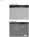
Figs. 3 (a) and 3 (b) are sectional images of a ceramic ball of Example 1. -
Figs. 4 (a) and 4 (b) are sectional images of a ceramic ball of Example 18. -
Figs. 5 (a) and 5 (b) are sectional images of a ceramic ball of Comparative example 1. -
Fig. 6 is one example of an image of a crystal orientation map by an EBSD measurement. -
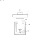
Fig. 7 is a general view showing a crushing test. - Hereinafter, an embodiment of the present invention is described.
- A silicon nitride sintered body according to the present invention contains β-type silicon nitride particle as a main component, and at least a rare earth element and an aluminum element. The rare earth element is derived from a sintering additive containing a rare earth element, employed in producing the silicon nitride sintered body. The aluminum element is derived from a sintering additive containing an aluminum element, employed in producing the silicon nitride sintered body. Each of the rare earth element and the aluminum element forms a grain boundary phase of, for example, a Si-RE-Al-O-N compound (RE is a rare earth element), which densifies the silicon nitride sintered body.
- Examples of the rare earth element in the silicon nitride sintered body include, but not especially limited thereto, yttrium (Y), lanthanum (La), cerium (Ce), samarium (Sm), neodymium (Nd), dysprosium (Dy), europium (Eu), and erbium (Er). The silicon nitride sintered body may contain only one or two or more of these rare earth elements. Of these rare earth elements, yttrium (Y), lanthanum (La), and erbium (Er) are preferable from a viewpoint of adjustment of the crystal grain diameter. Examples of the sintering additive containing the rare earth element include oxide of the rare earth element and nitride of the rare earth element.
- The content of the rare earth element is, for example, 2-20 wt% in terms of oxide, relative to the total weight of the silicon nitride sintered body. With the content of the rare earth element within the above-described range, the silicon nitride sintered body is easily densified and the amount of the grain boundary phase is suppressed, so that superior mechanical strength of the silicon nitride sintered body can be obtained. The content of the rare earth element is preferably 2-15 wt%, may be 4-10 wt% or 4-6 wt%.
- The content of the aluminum element is, for example, 0.5-10 wt% in terms of oxide, relative to the total weight of the silicon nitride sintered body. With the content of the aluminum element within the above-described range, the silicon nitride sintered body is easily densified and the amount of the grain boundary phase is suppressed, so that superior mechanical strength of the silicon nitride sintered body can be obtained. The content of the aluminum element is preferably 0.5-6 wt%, may be 2-6 wt%. Examples of the sintering additive containing the aluminum element include aluminum oxide and aluminum nitride.
- In the silicon nitride sintered body, the content of the rare earth element (in terms of oxide) and the content of the aluminum element (in terms of oxide) may be identical to each other, or the content of the rare earth element (in terms of oxide) may be larger or smaller than the content of the aluminum element (in terms of oxide). The total of the content of the rare earth element (in terms of oxide) and the content of the aluminum element (in terms of oxide) is, for example, 2-18 wt%, preferably 4-15 wt%, more preferably 9-13 wt%, relative to the total weight of the silicon nitride sintered body.
- In a case in which the oxide of the rare earth element is employed as a sintering additive, the content of the rare earth element may be calculated as an adding amount of the sintering additive relative to the total amount of the raw material powder. In a case in which aluminum oxide (Al2O3) is employed as a sintering additive, the content of the aluminum element may be calculated as a content of the sintering additive relative to the total amount of the raw material powder.
- Further, the content of each of the rare earth element and the aluminum element is determined using an X-ray fluorescence analysis device (XRF), an energy dispersive X-ray spectroscopy (EDX), or an inductively coupled plasma (ICP) atomic emission spectroscopy. Specifically, the content of each of the rare earth element and the aluminum element in the silicon nitride sintered body is determined using the above-described device and is converted into the oxide of the rare earth element (RE) (RE2O3 or REO2) or the aluminum oxide (Al2O3).
- The silicon nitride sintered body may contain a component other than the rare earth element and the aluminum element, derived from the sintering additive.
- The silicon nitride sintered body may further contain at least one metal element selected from among titanium (Ti), zirconium (Zr), hafnium (Hf), tungsten (W), molybdenum (Mo), tantalum (Ta), niobium (Nb), iron (Fe), and chromium (Cr). These metal elements may be added into the raw material powder as, for example, metal simple substance, oxide of the metal element, or nitride of the metal element.
- The content of the metal element (the total content in a case of two or more elements) is, for example, 0.1-5 wt%, preferably 0.5-3 wt%, or 1-3 wt% in terms of oxide, relative to the total weight of the silicon nitride sintered body. The content of the metal element may be calculated by the method similar to those for the rare earth element and the aluminum element.
- The silicon nitride sintered body may contain iron (Fe) as the metal element. The content of the iron may be, for example, 0.05 wt% or more, or 0.1 wt% or more, relative to the total weight of the silicon nitride sintered body. The iron contained in the silicon nitride sintered body can improve the fracture toughness of the silicon nitride sintered body and suppress the progress of a crack. However, in a case in which the content of the iron becomes larger, an iron particle is exposed to a sphere surface and the exposed iron particle is desulfied, which might cause the flaking. From such a viewpoint, the content of the iron is preferably less than 0.5 wt%, relative to the total weight of the silicon nitride sintered body. The iron is added into the raw material powder as, for example, iron powder or iron oxide (Fe2O3).
- Shape characteristics of β-type silicon nitride particle in the silicon nitride sintered body are now described. There are α-phase and β-phase as phases of the silicon nitride powder. A particle of the β-phase is deposited when the particle transits from the α-phase to the β-phase in sintering, and then the particle grows up and forms an anisotropic shape structure.
- In one aspect of the silicon nitride sintered body according to the present invention, at least one of a crystal grain diameter and an aspect ratio of a β-type Si3N4 particle within a specified measurement range, is set in a specified numeral range. The crystal grain diameter and the aspect ratio are calculated by an analysis based on an electron back scattering diffraction (EBSD) method. The EBSD method uses, for example, a Field Emission Scanning Electron Microscope (FE-SEM) to analyze a crystal orientation based on an EBSD pattern obtained through the EBSD. The magnification of the FE-SEM image used in the analysis is, for example, 1,000-2,000.
-
Fig. 1 is a general view showing a measuring principle of the EBSD method. As shown inFig. 1 , a specified surface of a test piece (the silicon nitride sintered body) placed in the field emission scanning electron microscope is irradiated with an electron ray to acquire a diffraction pattern of the electron ray reflected on the surface, by a detector. The test piece is placed to set an appropriate angle between the test piece and a plane orthogonal to an optical axis of the electron ray that is incident on the test piece. The EBSD pattern is projected on a fluorescent screen of the detector, and a surface of the test piece is scanned with the electron ray, so that orientation information is mapped. Accordingly, the crystal orientation in a specified local area of the crystalline material can be obtained.Fig. 1 shows an analysis based on a reflection EBSD method, however an analysis based on a transmission EBSD method may be also employed. - The crystal grain diameter and the aspect ratio are calculated from a range where the sum of the area of the upper-size crystal grain diameters is 30% relative to the area of the total crystal grain diameter as a group of the crystal grain diameters of the β-type Si3N4 particles having the same crystal orientation within a range of the crystal orientation of 15-180 degrees is deemed as one crystal grain diameter. The range fulfills the confidence index (CI) of 0.1 or more.
- The above-described silicon nitride sintered body fulfills at least one of that the crystal grain diameter of the β-type Si3N4 particle in the above-described range is 1-4 µm by circle equivalent diameter and that the aspect ratio of the β-type Si3N4 particle in the above-described range is 3-6. Thus, as described in the following example, superior crushing strength and superior mechanical property can be obtained. Also, such a setting of the crystal grain diameter and the aspect ratio can suppress generation of pores. The crystal grain diameter is preferably 1-3 µm. The aspect ratio is preferably 3-5.
- The crystal grain diameter of the β-type Si3N4 particle is calculated by the following formula (1).
Math 1
- The "area of crystal grain diameter particle in a group of same crystal orientation" in the formula (1) is calculated using software.
- The aspect ratio is a ratio (L/S) of a long side L to a short side S of the β-type Si3N4 particle in the above-described range. Specifically, the long side L and the short side S of each β-type Si3N4 particle are measured and each aspect ratio is calculated. The aspect ratio is an average of the calculated aspect ratios. The dense of the silicon nitride sintered body can be enhanced by employing the shapes of the β-type Si3N4 particles within a specified aspect range.
- In the above-described silicon nitride sintered body, it is preferable that an area ratio of a snowflake in an image of any section acquired at magnification of 100, relative to the total sectional area in the image is 7% or less. The area ratio of the snowflake is more preferably 5% or less, further more preferably 3% or less. The snowflake is aggregate of fine defects, which affect wear resistance or durability, and thus small area ratio of the snowflake is preferable.
- As described in the following example, the snowflake is observed as a white spot by a dark-field SEM observation on the section. The snowflake cannot be observed by a bright-field SEM observation. An area ratio of the snowflake is calculated by binarizing a dark-field SEM image using an image analyzing software.
- It is preferable that the silicon nitride sintered body of the present invention does not have a pore of 50 µm or more in a surface layer portion (for example, a portion within 500 µm from the surface of the silicon nitride sintered body), more preferable that the silicon nitride sintered body does not have a pore of 30 µm or more, and further more preferable that the silicon nitride sintered body does not have a pore of 10 µm or more. The presence of the pore in the surface layer portion might cause flaking from the pore as a starting point. The pore may be checked by the SEM observation on a cutting surface of the silicon nitride sintered body to which a mirror polishing is applied. The diameter of the pore may be calculated as, for example, a square root of an enveloping area of the pore (the diameter of the pore = √ (the enveloping area of the pore)) .
- The silicon nitride sintered body of the present invention has superior mechanical property, and for example, it is preferable that the crushing strength of a 3/8 inch ball formed of the silicon nitride sintered body is 20 kN or more. The crush strength may be, for example, 30 kN or less. The crushing strength may be measured by, for example, a two balls crushing test described in the following example.
- In another aspect of the silicon nitride sintered body of the present invention, an area ratio of the snowflake in an image of any section acquired at magnification of 100, relative to the total area of the image is 7% or less. In this aspect, the area ratio of the snowflake is preferably 5% or less, and more preferably 3% or less.
- Another aspect may also have the shape characteristics and physical property of the above-described silicon nitride sintered body.
- Manufacturing of the silicon nitride sintered body of the present invention is now described.
- The silicon nitride sintered body of the present invention is basically manufactured through a mixing step that mixes raw material powder containing a silicon nitride powder and a sintering additive, a molding step that molds the obtained mixed powder into a molded body, and a sintering step that sinters the molded body.
- In the mixing step, a specified amount of a binder component (for example, organic binder) is added to the raw material powder and mixed together using a ball mill so as to form a molding powder. In the molding step, a molded body having a desired shape is formed from the molding powder through a known molding method such as a CIP (Cold Isostatic Press) molding and a press molding. A degreasing step may be performed as needed after the molding step. The degreasing step is performed by, for example, heating the molded body at a specified temperature in a degreasing furnace.
- In the sintering step, a heat treatment in an inert atmosphere such as a nitrogen atmosphere and an argon atmosphere, at a temperature of 1, 600-1, 950 °C (preferably 1, 600-1, 900 °C) is applied to the molded body, so as to sinter the molded body. The sintering time is, for example, 3-10 hours. Examples of the sintering method include a pressureless sintering, an atmospheric pressure sintering, and a pressure sintering (hot pressing). In the atmospheric pressure sintering, the pressure is set to, for example, 0.1-10 MPa. In the sintering step, a primary sintering and a secondary sintering may be performed under different pressures.
- The obtained sintered body may be subjected to a HIP (Hot Isostatic Press) treatment after the sintering step. The HIP treatment is performed by, for example, keeping a temperature of 1,500-1,700 °C for a specified time under gas pressure of 100 MPa or more.
- In manufacturing the silicon nitride sintered body, the content of the silicon nitride powder employed in the raw material powder may be preferably 70-97 wt%, more preferably 80-97 wt%, or 85-92 wt%, relative to the total weight (excluding a binder component in mixing) of the raw material powder. The mean particle diameter of the silicon nitride powder may be, for example, 0.5 µm or less.
- As the sintering additive employed in the raw material powder, a sintering additive containing a rare earth element and a sintering additive containing an aluminum element are employed, and a sintering additive containing an oxide of a rare earth element and a sintering additive containing an oxide of an aluminum element are preferably employed. Examples of the sintering additive containing a rare earth element include Y2O3, La2O3, CeO2, Sm2O3, Nd2O3, Dy2O3, Eu2O3, and Er2O3. Only one or two or more of these sintering additives may be employed.
- The raw material powder may contain materials other than the silicon nitride powder, the sintering additive containing the rare earth element, and the sintering additive containing the aluminum element. For example, a metal compound containing at least one of titanium (Ti), zirconium (Zr), hafnium (Hf), tungsten (W), molybdenum (Mo), tantalum (Ta), niobium (Nb), iron (Fe), and chromium (Cr) may be added into the raw material powder. The metal compound may be added into the raw material powder as, for example, metal simple substance, oxide of the metal element, or nitride of the metal element. For example, the metal compound may be added into the raw material powder as a sintering additive containing a transition metal element, such as TiO2, Fe2O3, and Cr2O3.
- The mean particle diameter of the sintering additive may be normally 10 µm or less, 5 µm or less, 3 µm or less, 1 µm or less, or 0.4 µm or less, which depends on the type of the sintering additive.
- The shape of the silicon nitride sintered body of the present invention is not especially limited, and thus a spherical shape, a cylindrical shape, a conical shape, a truncated conical shape, or a rectangular parallelepiped shape may be appropriately selected based on its usage.
- The silicon nitride sintered body of the present invention is suitably applied to a machine part used in a rolling portion or a sliding portion because of its superior mechanical property and sliding property. The machine part of the present invention employs the silicon nitride sintered body of the present invention in a portion or the whole of its structure. Examples of the machine part include a sliding member, a bearing component, a roll material for rolling, a compressor vane, and an engine component such as a gas turbine vane. Examples of the bearing member include an inner ring raceway ring, an outer ring raceway ring, a bearing rolling element, and a cage. A bearing of the present invention employs the machine part in a portion or the whole of its structure. Examples of the bearing include a rolling bearing, a sliding bearing, a linear guide bearing, a ball screw, and a linear bearing. In particular, a rolling bearing that employs the silicon nitride sintered body in a bearing rolling element is preferable as the bearing of the present invention because of its superior rolling lifetime.
-
Fig 2 shows one example to which the silicon nitride sintered body is applied.Fig. 2 is a sectional view of a deep groove ball bearing. A rollingbearing 1 includes aninner ring 2 having an inner ring raceway surface 2a on an outer peripheral surface, anouter ring 3 having an outer ring raceway surface 3a on an inner peripheral surface, and a plurality of balls (rolling elements) 4 disposed between the inner ring raceway surface 2a and the outer ring raceway surface 3a. Theinner ring 2 and theouter ring 3 are disposed coaxially to each other. Theballs 4 are formed by the silicon nitride sintered body. Theball 4 is retained by a cage 5. Both openings 8a, 8b in an axial direction of the inner and outer rings are sealed by seal member 6, and agrease composition 7 is sealed around at least theballs 4. Thegrease composition 7 is interposed between theballs 4 and the raceway surfaces to lubricate theballs 4. In the example shown inFig. 2 , the silicon nitride sintered body is applied to the ball, however the silicon nitride sintered body may be applied to a roller in a case of a roller bearing. - A specified amount of an organic binder was added to the raw material powder having the compound rate shown in Table 1, and they were mixed by a ball mill to form a molded body by the CIP method. The obtained molded body was degreased in a degreasing furnace and sintered in a nitrogen atmosphere (pressure of normal pressure) for four hours at a temperature of 1,750 °C. Further, the HIP treatment was applied to the obtained sintered body in a nitrogen atmosphere (pressure of 100 MPa) for one hour at a temperature of 1,700 °C to form the silicon nitride sintered body.
- A specified amount of an organic binder was added to the raw material powder having the compound rate shown in Table 1, and they were mixed by a ball mill and press-molded at a molding pressure of 30MPa to form the molded body by the CIP method. Thereafter, the molded body was subjected to a primary sintering in a nitrogen atmosphere (pressure of 0.1 MPa) for three hours at a temperature of 1,650 °C and then a secondary sintering in a nitrogen atmosphere (pressure of 8 MPa) for three hours at a temperature of 1,650 °C.
- The obtained silicon nitride sintered body was polished to form a ceramic ball having 3/8 inches (diameter of 9.525 mm) . Various physical properties and rolling fatigue performance thereof were evaluated.
Table 1 Raw material powder (wt%) Si3N4 Rare earth element Al element Oxide of Ti, W, Mo, etc. Fe powder Y2O3 Er2O3 La2O3 Al2O3 Example 1 residual 4 - - 5 1 - Example 2 residual 6 - - 6 2 - Example 3 residual - 4 - 5 1 - Example 4 residual - 5 - 6 2 - Example 5 residual - 4 - 5 1 - Example 6 residual - 5 - 6 2 - Example 7 residual 2 - - 2 1 0.1 Example 8 residual 2 - - 2 1 0.4 Example 9 residual 6 - - 3 1 0.4 Example 10 residual 6 - - 3 2 0.4 Example 11 residual - - 2 0.5 1 - Example 12 residual - - 2 3 1 - Example 13 residual - - 10 0.5 1 - Example 14 residual - - 10 3 1 - Example 15 residual - - 15 0.5 1 - Example 16 residual - - 15 3 1 - Example 17 residual - - 15 3 2.5 - Example 18 residual 10 - - 6 2 - Example 19 residual 6 - - 10 2 - Example 20 residual - 10 - 5 2 - Example 21 residual - 4 - 10 2 - Example 22 residual 6 - - 3 - 0.5 Example 23 residual - - 20 3 1 - Example 24 residual - - 5 10 1 - Comparative example 1 residual 1 - - 1 1 - Comparative example 2 residual - 2 - 5 2 - Comparative example 3 residual - - 1 1 1 - - The ceramic ball of each of Examples and Comparative examples was cut and the section thereof was observed. The representative sectional images of Example 1 (see
Figs. 3(a) and 3(b) ), Example 18 (seeFigs. 4(a) and 4(b) ), and Comparative example 1 (seeFigs. 5(a) and 5(b) ) are exemplarily shown. In the figures, the figure (a) corresponds to a bright-field image, and the figure (b) corresponds to a dark-field image. - Example 1 shown in
Figs. 3(a) and 3(b) has no pores in the surface layer portion and almost no snowflakes, which means dense silicon nitride sintered body. The same results are shown in Examples 2-17. Example 18 shown inFigs. 4(a) and 4(b) has no pores in the surface layer portion, but many snowflakes because much sintering additive is added thereto. The same results are shown in Examples 19-21, 23, and 24. Comparative example 1 of which the adding amount of the sintering additive is relatively small has some pores in the surface layer portion. Similar pores are shown in Comparative examples 2 and 3. - The ceramic ball of each of Examples and Comparative examples was measured by the EBSD method. A Field Emission Scanning Electron Microscope (FE-SEM) was used for the measurement. As shown in
Fig. 1 , a crystal orientation of the surface (observation field) of each ceramic ball as a test piece was analyzed.Fig. 6 shows an image of the crystal orientation map of the observation field. The map image is colored by the crystal orientation of the β-type Si3N4 particle. A group of the same crystal orientation within a range of 15-180 degrees in the crystal orientation is defined as one crystal grain diameter in the crystal orientation map image. The crystal grain diameter and the aspect ratio were calculated in a range where the sum of the area of the upper-size crystal grain diameter is 30% relative to the area of the total crystal grain diameter. The above-described range fulfills the confidence index (CI) of 0.1 or more in the analysis software. - Specifically, the area of each grain at each crystal orientation was obtained through the image analysis within the above-described range, and then the diameter of a circle (circle equivalent diameter) that is equal to the area was calculated based on the above-described formula (1). The mean of the diameters is defined as a crystal grain diameter (mean crystal grain diameter) . Further, a long side (L) and a short side (S) of each grain at each crystal orientation were obtained through the image analysis within the above-described range, and then the aspect ratio (L/S) was calculated. The mean of the aspect ratios is defined as an aspect ratio (mean aspect ratio).
- The measurement was executed three times while changing an area to be analyzed on the surface of each ceramic ball, and the mean values thereof are calculated as the crystal grain diameter and the aspect ratio (the number of measurements is 3) . The magnification of the FE-SEM image used in this process was 2,000. The result is shown in Table 2.
- An image processing was executed on one visual field of a cutting image of the ceramic ball of each of Examples and Comparative examples so as to measure the area ratio of the snowflake. Image processing software WinRoof 2013 was employed for the image processing. The image obtained at magnification of 100 was binarized and the area ratio was calculated by the following formula (2).
Area ratio of snowflake (%) = Area of snowflake + total sectional area × 100 - The "total sectional area" in the formula (2) denotes a total sectional area of the ceramic ball in one target visual field. Thus, the "total sectional area" includes the area of the snowflake. The result is shown in Table 2.
- A two balls crushing test was executed on the ceramic ball of each of Examples and Comparative examples . The crushing test is based on JIS B 1501. As shown in
Fig. 7 , a crushing tester has a fixed jig 9 and amovable jig 10. Themovable jig 10 is moved up and down by a cross head 11. Each of the fixed jig 9 and themovable jig 10 has a conical recess. Twotest balls 12 are disposed between the recesses. A stroke speed of the cross head 11 is set to 1.0 × 10 mm/minute. A load when thetest ball 12 is crushed was measured. The result is shown in Table 2. - In order to evaluate the rolling fatigue performance of a ceramic ball of each of Examples and Comparative examples, a rolling bearing of "deep groove ball bearing 6206" produced by NTN CORPORATION with each ceramic ball was prepared, and then a bearing lifetime (rolling lifetime) test was executed on the rolling bearing under the following condition. The censoring time (maximum test time) of the bearing lifetime test is set to 600 hours. The result is shown in Table 2.
- Load (kN): Fr = 13.72 (6.86 kN/brg)
- Maximum contact surface pressure (GPa) : 3.5 between inner ring and ball, 3.6 between outer ring and ball
- Rotation speed (minute-1) : 3,000
- Lubrication oil: inorganic turbine oil VG56 produced by JXTG ENERGY CORPORATION
- Lubrication oil supply temperature (°C): 50
- Oil supply method: cleaning oil circulation
- As shown in Table 2, in each of Comparative examples 1 to 3, the crystal grain diameter is less than 1 µm, which is smaller than those in Examples 1 to 24. This is because that the adding amount of the sintering additive in each of Comparative examples 1 to 3 is relatively small, which results in insufficient densifying by the sintering. In addition, the pore is caused due to the insufficient densifying, in the section observation (see
Figs. 5 (a) and 5(b) ). In each of Examples 1 to 24, the crystal grain diameter of the β-type silicon nitride particle is 1-4 µm and the aspect ratio thereof is 3-6. The crystal grain diameter and the aspect ratio become larger as the adding amount of the sintering additive is larger. - There is a correlation between the adding amount of the sintering additive and the area ratio of the snowflake to some extent. In each of Examples 18-21, 23 and 24 in which the adding amounts of the sintering additive are relatively large, the area ratio of the snowflake exceed 7% (specifically, 7.11-8.45%). In the other Examples, the area ratios of the snowflake are less than 7%.
- In each of Examples 1 to 24, the crushing strength is 20 kN or more, while in each of Comparative examples 1 to 3, the crushing strength is less than 20 kN, which is inferior. It is considered that this result is affected by the pore that is observed in the section observation.
- In each of Examples 1 to 17, the test time exceeds the censoring time of 600 hours, so that the rolling fatigue test was ended at the censoring time. In each of Examples 18 to 24 and Comparative examples 1 to 3, flaking is caused before the censoring time of 600 hours. In each of Comparative examples 1 to 3, the flaking is caused in less than 200 hours, which is considered that the flaking is caused from the pore as a starting point. In each of Examples 18 to 21, 23 and 24, it is considered that the flaking is caused from the snowflake as a starting point. In Example 22, iron powder is added for improving the fracture toughness, however the adding amount of the iron powder is relatively large, so that the iron power is easily exposed to the sphere surface and the exposed iron powder is desulfied, which leads to the flaking.
- According to the above-described result, from a viewpoint of the crushing strength, Examples 1 to 24 in which the crystal grain diameters of the β-type silicon nitride particle are 1-4 µm and the aspect ratios thereof are 3-6 within the specified measurement range, show superior results. Of these Examples, Examples 1 to 17 in which the area ratios of the snowflake are 7% or less, show superior results also in the rolling fatigue performance. Thus, the present invention can realize the silicon nitride sintered body that is superior in mechanical property and sliding property.
- The silicon nitride sintered body of the present invention is superior in mechanical property and sliding property, and thus the silicon nitride sintered body is widely used as a machine part to which high mechanical property is required. For example, in a case in which the silicon nitride sintered body is applied to a bearing rolling element, flaking caused from a defect can be suppressed, and thus long lifetime can be realized.
-
- 1:
- rolling bearing
- 2:
- inner ring
- 3:
- outer ring
- 4:
- rolling element
- 5:
- cage
- 6:
- seal member
- 7:
- grease
- 8a, 8b:
- opening
- 9:
- fixed jig
- 10:
- movable jig
- 11:
- cross head
- 12:
- test ball
| Crystal grain diameter (µm) | Aspect ratio (L/S) | Area ratio of snowflake (%) | Crushing strength (kN) | Rolling fatigue lifetime (hours) | |
| Example 1 | 1.18 | 3.55 | 2.07 | 22.8 | 600 < |
| Example 2 | 1.45 | 4.08 | 2.30 | 21.5 | 600 < |
| Example 3 | 1.22 | 3.82 | 2.12 | 23.8 | 600 < |
| Example 4 | 1.34 | 4.21 | 2.85 | 22.2 | 600 < |
| Example 5 | 1.18 | 3.11 | 2.04 | 23.3 | 600 < |
| Example 6 | 1.37 | 4.34 | 2.76 | 21.4 | 600 < |
| Example 7 | 1.62 | 4.01 | 2.63 | 21.8 | 600 < |
| Example 8 | 1.71 | 4.03 | 1.08 | 21.3 | 600 < |
| Example 9 | 2.32 | 4.44 | 1.24 | 23.4 | 600 < |
| Example 10 | 3.27 | 5.97 | 1.31 | 23.3 | 600 < |
| Example 11 | 1.21 | 3.05 | 2.10 | 22.4 | 600 < |
| Example 12 | 1.66 | 3.22 | 2.31 | 21.1 | 600 < |
| Example 13 | 1.52 | 3.33 | 2.21 | 22.2 | 600 < |
| Example 14 | 1.61 | 3.50 | 2.76 | 21.5 | 600 < |
| Example 15 | 1.22 | 3.77 | 3.50 | 23.1 | 600 < |
| Example 16 | 1.55 | 3.82 | 4.31 | 22.2 | 600 < |
| Example 17 | 1.78 | 4.91 | 5.10 | 21.6 | 600 < |
| Example 18 | 1.81 | 4.51 | 7.32 | 23.0 | 421 |
| Example 19 | 1.89 | 4.60 | 8.21 | 22.5 | 411 |
| Example 20 | 1.76 | 4.55 | 7.11 | 23.4 | 432 |
| Example 21 | 1.78 | 4.45 | 7.56 | 22.2 | 426 |
| Example 22 | 3.11 | 5.76 | 1.42 | 23.1 | 210 |
| Example 23 | 2.10 | 5.20 | 8.45 | 23.4 | 285 |
| Example 24 | 2.21 | 5.28 | 7.50 | 22.7 | 360 |
| Comparative example 1 | 0.42 | 1.51 | 0.92 | 15.2 | 150 |
| Comparative example 2 | 0.80 | 2.11 | 1.01 | 17.0 | 172 |
| Comparative example 3 | 0.62 | 1.90 | 0.99 | 16.4 | 185 |
Claims (10)
- A silicon nitride sintered body comprising a silicon nitride particle, a rare earth element and an aluminum element,
wherein, in a range in which the sum of the area of the upper-size crystal grain diameter within a range where the crystal grain diameter of a β-type Si3N4 particle in the silicon nitride sintered body has the crystal orientation of 15-180 degrees, is 30% relative to an area of the total crystal grain diameter, the crystal grain diameter of the β-type Si3N4 particle is 1-4 µm by circle equivalent diameter and/or the aspect ratio of the β-type Si3N4 particle is 3-6. - The silicon nitride sintered body as defined in claim 1, comprising at least one metal element selected from among Ti, Zr, Hf, W, Mo, Ta, Nb, Fe, and Cr.
- The silicon nitride sintered body as defined in claim 1, wherein:the silicon nitride sintered body comprises Fe, andthe content of Fe is less than 0.5 wt% relative to the total weight of the silicon nitride sintered body.
- The silicon nitride sintered body as defined in claim 1, wherein a ratio of an area of a snowflake in an image of a section of the silicon nitride sintered body acquired at the magnification of 100 is 7% or less relative to the total sectional area in the image.
- The silicon nitride sintered body as defined in claim 1, wherein the crushing strength of a 3/8 inch ball formed of the silicon nitride sintered body is 20 kN or more.
- A silicon nitride sintered body comprising a silicon nitride particle, a rare earth element and an aluminum element,
wherein a ratio of an area of a snowflake in an image of a section of the silicon nitride sintered body acquired at the magnification of 100 is 7% or less relative to the total sectional area in the image. - A machine part comprising the silicon nitride sintered body as defined in claim 1.
- The machine part as defined in claim 7, configured as a bearing rolling element.
- The machine part as defined in claim 8, wherein the bearing rolling element has a rolling lifetime of 600 hours or more measured by a radial-type bearing tester under a condition of the maximum contact surface pressure of 3.6 GPa and the rotation speed of 3,000 minute-1.
- A bearing comprising the machine part as defined in claim 7, as a bearing component.
Applications Claiming Priority (2)
| Application Number | Priority Date | Filing Date | Title |
|---|---|---|---|
| JP2021140548A JP7780891B2 (en) | 2021-08-30 | 2021-08-30 | Silicon nitride sintered body, machine parts and bearings |
| PCT/JP2022/031184 WO2023032695A1 (en) | 2021-08-30 | 2022-08-18 | Silicon nitride sintered body, machine part, and bearing |
Publications (2)
| Publication Number | Publication Date |
|---|---|
| EP4397643A1 true EP4397643A1 (en) | 2024-07-10 |
| EP4397643A4 EP4397643A4 (en) | 2025-01-01 |
Family
ID=85411081
Family Applications (1)
| Application Number | Title | Priority Date | Filing Date |
|---|---|---|---|
| EP22864280.7A Pending EP4397643A4 (en) | 2021-08-30 | 2022-08-18 | SILICON NITRIDE SINTERED BODY, MACHINE PART AND BEARING |
Country Status (5)
| Country | Link |
|---|---|
| US (1) | US20240425419A1 (en) |
| EP (1) | EP4397643A4 (en) |
| JP (1) | JP7780891B2 (en) |
| CN (1) | CN117836256A (en) |
| WO (1) | WO2023032695A1 (en) |
Families Citing this family (1)
| Publication number | Priority date | Publication date | Assignee | Title |
|---|---|---|---|---|
| JP2025173928A (en) * | 2024-05-15 | 2025-11-28 | Ntn株式会社 | Silicon nitride sintered body, machine parts and bearings |
Family Cites Families (16)
| Publication number | Priority date | Publication date | Assignee | Title |
|---|---|---|---|---|
| JPH075390B2 (en) * | 1989-07-18 | 1995-01-25 | 住友電気工業株式会社 | Method for producing high-strength silicon nitride sintered body |
| JPH06122563A (en) | 1992-10-12 | 1994-05-06 | Sumitomo Electric Ind Ltd | Ceramic composite material and manufacturing method thereof |
| JP3042402B2 (en) * | 1996-04-26 | 2000-05-15 | 住友電気工業株式会社 | Silicon nitride ceramic sliding material and method for producing the same |
| JP4795588B2 (en) | 2001-01-12 | 2011-10-19 | 株式会社東芝 | Wear resistant parts made of silicon nitride |
| JP4820505B2 (en) | 2001-08-27 | 2011-11-24 | 株式会社東芝 | Wear-resistant member for electronic equipment and bearing for electronic equipment using the same |
| JP4693374B2 (en) * | 2004-07-22 | 2011-06-01 | 株式会社東芝 | Manufacturing method of sintered silicon nitride |
| CN104692806B (en) * | 2007-03-15 | 2017-04-26 | 株式会社东芝 | Sliding member |
| JP5100201B2 (en) | 2007-05-16 | 2012-12-19 | 株式会社東芝 | Silicon nitride sintered body and sliding member using the same |
| WO2009128386A1 (en) | 2008-04-18 | 2009-10-22 | 株式会社東芝 | Anti-wear member, anti-wear instrument and method of producing anti-wear member |
| JP5268750B2 (en) | 2009-04-01 | 2013-08-21 | 株式会社東芝 | Impact resistant member and manufacturing method thereof |
| JP5945382B2 (en) | 2010-01-07 | 2016-07-05 | 株式会社ニッカトー | Silicon nitride sintered body and wear-resistant member |
| CN106966735A (en) | 2010-02-16 | 2017-07-21 | 株式会社东芝 | Anti-wear component and the method for manufacturing the anti-wear component |
| WO2014069268A1 (en) | 2012-10-30 | 2014-05-08 | 株式会社東芝 | Silicon nitride sintered body and wear resistant member using same |
| JP5989602B2 (en) | 2013-05-29 | 2016-09-07 | 日本特殊陶業株式会社 | Silicon nitride sintered body, manufacturing method thereof, and rolling element for bearing |
| US9663407B2 (en) | 2013-06-13 | 2017-05-30 | Kabushiki Kaisha Toshiba | Silicon nitride wear resistant member and method for producing silicon nitride sintered compact |
| EP3760581B1 (en) | 2018-02-28 | 2022-07-06 | Tokuyama Corporation | Silicon nitride powder for sintering |
-
2021
- 2021-08-30 JP JP2021140548A patent/JP7780891B2/en active Active
-
2022
- 2022-08-18 EP EP22864280.7A patent/EP4397643A4/en active Pending
- 2022-08-18 US US18/684,815 patent/US20240425419A1/en active Pending
- 2022-08-18 WO PCT/JP2022/031184 patent/WO2023032695A1/en not_active Ceased
- 2022-08-18 CN CN202280056417.2A patent/CN117836256A/en active Pending
Also Published As
| Publication number | Publication date |
|---|---|
| US20240425419A1 (en) | 2024-12-26 |
| EP4397643A4 (en) | 2025-01-01 |
| CN117836256A (en) | 2024-04-05 |
| JP2023034353A (en) | 2023-03-13 |
| JP7780891B2 (en) | 2025-12-05 |
| WO2023032695A1 (en) | 2023-03-09 |
Similar Documents
| Publication | Publication Date | Title |
|---|---|---|
| US7056850B2 (en) | Wear-resistant silicon nitride member and method of manufacture thereof | |
| US8133830B2 (en) | Silicon nitride sintered compact and sliding member using the same | |
| EP1223150B1 (en) | Silicon nitride wear resistant member and method of manufacturing the member | |
| JP6400478B2 (en) | Wear-resistant material | |
| JP5944910B2 (en) | Silicon nitride sintered body and method for manufacturing the same, and wear-resistant member and bearing using the same | |
| US7521388B2 (en) | Wear resistant member comprised of silicon nitride and process for producing the same | |
| EP3281927B1 (en) | Silicon nitride sintered body and high-temperature-resistant member using the same | |
| US20250187987A1 (en) | Silicon nitride sintered body, wear-resistant member using the same, and method for producing silicon nitride sintered body | |
| US11097374B2 (en) | Friction stir welding tool member made of silicon nitride sintered body, and friction stir welding apparatus using the same | |
| US20240425419A1 (en) | Silicon nitride sintered body, machine part, and bearing | |
| WO2015099148A1 (en) | Wear-resistant member and rolling support device provided with same, and shaft sealing device | |
| US20230382809A1 (en) | Silicon Nitride Sintered Body, Wear-Resistant Member, And Method For Manufacturing Silicon Nitride Sintered Body | |
| US20260042709A1 (en) | Silicon nitride-type sintered body, bearing rolling element, silicon nitride-type blank ball, and bearing | |
| WO2025239404A1 (en) | Silicon nitride sintered body, machine component, and bearing | |
| WO2021235343A1 (en) | Silicon nitride sintered body, wear-resistant member using same, and method for manufacturing silicon nitride sintered body | |
| JP7601582B2 (en) | Ceramic sintered body, bearing ball, and bearing | |
| JP2026082181A (en) | Silicon nitride sintered body, sliding member, and bearing | |
| JP7840733B2 (en) | Silicon nitride spheres, rolling elements, and rolling bearings | |
| WO2025053251A1 (en) | Ceramic sintered body, abrasion resistant member, and method for producing ceramic sintered body | |
| WO2025041805A1 (en) | Silicon nitride sintered body and wear-resistant member using same | |
| WO2023145672A1 (en) | Silicon nitride sintered body, machine component using same, and bearing |
Legal Events
| Date | Code | Title | Description |
|---|---|---|---|
| STAA | Information on the status of an ep patent application or granted ep patent |
Free format text: STATUS: THE INTERNATIONAL PUBLICATION HAS BEEN MADE |
|
| PUAI | Public reference made under article 153(3) epc to a published international application that has entered the european phase |
Free format text: ORIGINAL CODE: 0009012 |
|
| STAA | Information on the status of an ep patent application or granted ep patent |
Free format text: STATUS: REQUEST FOR EXAMINATION WAS MADE |
|
| 17P | Request for examination filed |
Effective date: 20240306 |
|
| AK | Designated contracting states |
Kind code of ref document: A1 Designated state(s): AL AT BE BG CH CY CZ DE DK EE ES FI FR GB GR HR HU IE IS IT LI LT LU LV MC MK MT NL NO PL PT RO RS SE SI SK SM TR |
|
| DAV | Request for validation of the european patent (deleted) | ||
| DAX | Request for extension of the european patent (deleted) | ||
| A4 | Supplementary search report drawn up and despatched |
Effective date: 20241202 |
|
| RIC1 | Information provided on ipc code assigned before grant |
Ipc: F16C 33/32 20060101ALI20241126BHEP Ipc: F16C 19/06 20060101ALI20241126BHEP Ipc: C04B 35/596 20060101AFI20241126BHEP |
|
| STAA | Information on the status of an ep patent application or granted ep patent |
Free format text: STATUS: EXAMINATION IS IN PROGRESS |
|
| 17Q | First examination report despatched |
Effective date: 20250714 |