EP4397583A1 - Vehicle - Google Patents
Vehicle Download PDFInfo
- Publication number
- EP4397583A1 EP4397583A1 EP22864643.6A EP22864643A EP4397583A1 EP 4397583 A1 EP4397583 A1 EP 4397583A1 EP 22864643 A EP22864643 A EP 22864643A EP 4397583 A1 EP4397583 A1 EP 4397583A1
- Authority
- EP
- European Patent Office
- Prior art keywords
- space
- vehicle according
- disposed
- power
- electric motor
- Prior art date
- Legal status (The legal status is an assumption and is not a legal conclusion. Google has not performed a legal analysis and makes no representation as to the accuracy of the status listed.)
- Pending
Links
Images







Classifications
-
- B—PERFORMING OPERATIONS; TRANSPORTING
- B62—LAND VEHICLES FOR TRAVELLING OTHERWISE THAN ON RAILS
- B62M—RIDER PROPULSION OF WHEELED VEHICLES OR SLEDGES; POWERED PROPULSION OF SLEDGES OR SINGLE-TRACK CYCLES; TRANSMISSIONS SPECIALLY ADAPTED FOR SUCH VEHICLES
- B62M6/00—Rider propulsion of wheeled vehicles with additional source of power, e.g. combustion engine or electric motor
- B62M6/40—Rider propelled cycles with auxiliary electric motor
- B62M6/45—Control or actuating devices therefor
-
- B—PERFORMING OPERATIONS; TRANSPORTING
- B62—LAND VEHICLES FOR TRAVELLING OTHERWISE THAN ON RAILS
- B62J—CYCLE SADDLES OR SEATS; AUXILIARY DEVICES OR ACCESSORIES SPECIALLY ADAPTED TO CYCLES AND NOT OTHERWISE PROVIDED FOR, e.g. ARTICLE CARRIERS OR CYCLE PROTECTORS
- B62J43/00—Arrangements of batteries
- B62J43/20—Arrangements of batteries characterised by the mounting
- B62J43/23—Arrangements of batteries characterised by the mounting dismounted when charging
-
- B—PERFORMING OPERATIONS; TRANSPORTING
- B60—VEHICLES IN GENERAL
- B60K—ARRANGEMENT OR MOUNTING OF PROPULSION UNITS OR OF TRANSMISSIONS IN VEHICLES; ARRANGEMENT OR MOUNTING OF PLURAL DIVERSE PRIME-MOVERS IN VEHICLES; AUXILIARY DRIVES FOR VEHICLES; INSTRUMENTATION OR DASHBOARDS FOR VEHICLES; ARRANGEMENTS IN CONNECTION WITH COOLING, AIR INTAKE, GAS EXHAUST OR FUEL SUPPLY OF PROPULSION UNITS IN VEHICLES
- B60K1/00—Arrangement or mounting of electrical propulsion units
-
- B—PERFORMING OPERATIONS; TRANSPORTING
- B60—VEHICLES IN GENERAL
- B60L—PROPULSION OF ELECTRICALLY-PROPELLED VEHICLES; SUPPLYING ELECTRIC POWER FOR AUXILIARY EQUIPMENT OF ELECTRICALLY-PROPELLED VEHICLES; ELECTRODYNAMIC BRAKE SYSTEMS FOR VEHICLES IN GENERAL; MAGNETIC SUSPENSION OR LEVITATION FOR VEHICLES; MONITORING OPERATING VARIABLES OF ELECTRICALLY-PROPELLED VEHICLES; ELECTRIC SAFETY DEVICES FOR ELECTRICALLY-PROPELLED VEHICLES
- B60L50/00—Electric propulsion with power supplied within the vehicle
- B60L50/50—Electric propulsion with power supplied within the vehicle using propulsion power supplied by batteries or fuel cells
- B60L50/53—Electric propulsion with power supplied within the vehicle using propulsion power supplied by batteries or fuel cells in combination with an external power supply, e.g. from overhead contact lines
-
- B—PERFORMING OPERATIONS; TRANSPORTING
- B60—VEHICLES IN GENERAL
- B60L—PROPULSION OF ELECTRICALLY-PROPELLED VEHICLES; SUPPLYING ELECTRIC POWER FOR AUXILIARY EQUIPMENT OF ELECTRICALLY-PROPELLED VEHICLES; ELECTRODYNAMIC BRAKE SYSTEMS FOR VEHICLES IN GENERAL; MAGNETIC SUSPENSION OR LEVITATION FOR VEHICLES; MONITORING OPERATING VARIABLES OF ELECTRICALLY-PROPELLED VEHICLES; ELECTRIC SAFETY DEVICES FOR ELECTRICALLY-PROPELLED VEHICLES
- B60L50/00—Electric propulsion with power supplied within the vehicle
- B60L50/50—Electric propulsion with power supplied within the vehicle using propulsion power supplied by batteries or fuel cells
- B60L50/60—Electric propulsion with power supplied within the vehicle using propulsion power supplied by batteries or fuel cells using power supplied by batteries
- B60L50/66—Arrangements of batteries
-
- B—PERFORMING OPERATIONS; TRANSPORTING
- B60—VEHICLES IN GENERAL
- B60L—PROPULSION OF ELECTRICALLY-PROPELLED VEHICLES; SUPPLYING ELECTRIC POWER FOR AUXILIARY EQUIPMENT OF ELECTRICALLY-PROPELLED VEHICLES; ELECTRODYNAMIC BRAKE SYSTEMS FOR VEHICLES IN GENERAL; MAGNETIC SUSPENSION OR LEVITATION FOR VEHICLES; MONITORING OPERATING VARIABLES OF ELECTRICALLY-PROPELLED VEHICLES; ELECTRIC SAFETY DEVICES FOR ELECTRICALLY-PROPELLED VEHICLES
- B60L53/00—Methods of charging batteries, specially adapted for electric vehicles; Charging stations or on-board charging equipment therefor; Exchange of energy storage elements in electric vehicles
- B60L53/80—Exchanging energy storage elements, e.g. removable batteries
-
- B—PERFORMING OPERATIONS; TRANSPORTING
- B62—LAND VEHICLES FOR TRAVELLING OTHERWISE THAN ON RAILS
- B62J—CYCLE SADDLES OR SEATS; AUXILIARY DEVICES OR ACCESSORIES SPECIALLY ADAPTED TO CYCLES AND NOT OTHERWISE PROVIDED FOR, e.g. ARTICLE CARRIERS OR CYCLE PROTECTORS
- B62J43/00—Arrangements of batteries
- B62J43/10—Arrangements of batteries for propulsion
- B62J43/13—Arrangements of batteries for propulsion on rider-propelled cycles with additional electric propulsion
-
- B—PERFORMING OPERATIONS; TRANSPORTING
- B62—LAND VEHICLES FOR TRAVELLING OTHERWISE THAN ON RAILS
- B62J—CYCLE SADDLES OR SEATS; AUXILIARY DEVICES OR ACCESSORIES SPECIALLY ADAPTED TO CYCLES AND NOT OTHERWISE PROVIDED FOR, e.g. ARTICLE CARRIERS OR CYCLE PROTECTORS
- B62J43/00—Arrangements of batteries
- B62J43/10—Arrangements of batteries for propulsion
- B62J43/16—Arrangements of batteries for propulsion on motorcycles or the like
-
- B—PERFORMING OPERATIONS; TRANSPORTING
- B62—LAND VEHICLES FOR TRAVELLING OTHERWISE THAN ON RAILS
- B62J—CYCLE SADDLES OR SEATS; AUXILIARY DEVICES OR ACCESSORIES SPECIALLY ADAPTED TO CYCLES AND NOT OTHERWISE PROVIDED FOR, e.g. ARTICLE CARRIERS OR CYCLE PROTECTORS
- B62J43/00—Arrangements of batteries
- B62J43/20—Arrangements of batteries characterised by the mounting
-
- B—PERFORMING OPERATIONS; TRANSPORTING
- B62—LAND VEHICLES FOR TRAVELLING OTHERWISE THAN ON RAILS
- B62M—RIDER PROPULSION OF WHEELED VEHICLES OR SLEDGES; POWERED PROPULSION OF SLEDGES OR SINGLE-TRACK CYCLES; TRANSMISSIONS SPECIALLY ADAPTED FOR SUCH VEHICLES
- B62M6/00—Rider propulsion of wheeled vehicles with additional source of power, e.g. combustion engine or electric motor
- B62M6/40—Rider propelled cycles with auxiliary electric motor
-
- B—PERFORMING OPERATIONS; TRANSPORTING
- B62—LAND VEHICLES FOR TRAVELLING OTHERWISE THAN ON RAILS
- B62M—RIDER PROPULSION OF WHEELED VEHICLES OR SLEDGES; POWERED PROPULSION OF SLEDGES OR SINGLE-TRACK CYCLES; TRANSMISSIONS SPECIALLY ADAPTED FOR SUCH VEHICLES
- B62M6/00—Rider propulsion of wheeled vehicles with additional source of power, e.g. combustion engine or electric motor
- B62M6/80—Accessories, e.g. power sources; Arrangements thereof
- B62M6/90—Batteries
-
- B—PERFORMING OPERATIONS; TRANSPORTING
- B60—VEHICLES IN GENERAL
- B60L—PROPULSION OF ELECTRICALLY-PROPELLED VEHICLES; SUPPLYING ELECTRIC POWER FOR AUXILIARY EQUIPMENT OF ELECTRICALLY-PROPELLED VEHICLES; ELECTRODYNAMIC BRAKE SYSTEMS FOR VEHICLES IN GENERAL; MAGNETIC SUSPENSION OR LEVITATION FOR VEHICLES; MONITORING OPERATING VARIABLES OF ELECTRICALLY-PROPELLED VEHICLES; ELECTRIC SAFETY DEVICES FOR ELECTRICALLY-PROPELLED VEHICLES
- B60L2200/00—Type of vehicles
- B60L2200/12—Bikes
-
- B—PERFORMING OPERATIONS; TRANSPORTING
- B60—VEHICLES IN GENERAL
- B60L—PROPULSION OF ELECTRICALLY-PROPELLED VEHICLES; SUPPLYING ELECTRIC POWER FOR AUXILIARY EQUIPMENT OF ELECTRICALLY-PROPELLED VEHICLES; ELECTRODYNAMIC BRAKE SYSTEMS FOR VEHICLES IN GENERAL; MAGNETIC SUSPENSION OR LEVITATION FOR VEHICLES; MONITORING OPERATING VARIABLES OF ELECTRICALLY-PROPELLED VEHICLES; ELECTRIC SAFETY DEVICES FOR ELECTRICALLY-PROPELLED VEHICLES
- B60L2210/00—Converter types
- B60L2210/10—DC to DC converters
-
- B—PERFORMING OPERATIONS; TRANSPORTING
- B60—VEHICLES IN GENERAL
- B60L—PROPULSION OF ELECTRICALLY-PROPELLED VEHICLES; SUPPLYING ELECTRIC POWER FOR AUXILIARY EQUIPMENT OF ELECTRICALLY-PROPELLED VEHICLES; ELECTRODYNAMIC BRAKE SYSTEMS FOR VEHICLES IN GENERAL; MAGNETIC SUSPENSION OR LEVITATION FOR VEHICLES; MONITORING OPERATING VARIABLES OF ELECTRICALLY-PROPELLED VEHICLES; ELECTRIC SAFETY DEVICES FOR ELECTRICALLY-PROPELLED VEHICLES
- B60L2240/00—Control parameters of input or output; Target parameters
- B60L2240/40—Drive Train control parameters
- B60L2240/42—Drive Train control parameters related to electric machines
- B60L2240/421—Speed
-
- B—PERFORMING OPERATIONS; TRANSPORTING
- B60—VEHICLES IN GENERAL
- B60L—PROPULSION OF ELECTRICALLY-PROPELLED VEHICLES; SUPPLYING ELECTRIC POWER FOR AUXILIARY EQUIPMENT OF ELECTRICALLY-PROPELLED VEHICLES; ELECTRODYNAMIC BRAKE SYSTEMS FOR VEHICLES IN GENERAL; MAGNETIC SUSPENSION OR LEVITATION FOR VEHICLES; MONITORING OPERATING VARIABLES OF ELECTRICALLY-PROPELLED VEHICLES; ELECTRIC SAFETY DEVICES FOR ELECTRICALLY-PROPELLED VEHICLES
- B60L2250/00—Driver interactions
- B60L2250/16—Driver interactions by display
-
- B—PERFORMING OPERATIONS; TRANSPORTING
- B60—VEHICLES IN GENERAL
- B60Y—INDEXING SCHEME RELATING TO ASPECTS CROSS-CUTTING VEHICLE TECHNOLOGY
- B60Y2200/00—Type of vehicle
- B60Y2200/10—Road Vehicles
- B60Y2200/13—Bicycles; Tricycles
-
- B—PERFORMING OPERATIONS; TRANSPORTING
- B62—LAND VEHICLES FOR TRAVELLING OTHERWISE THAN ON RAILS
- B62M—RIDER PROPULSION OF WHEELED VEHICLES OR SLEDGES; POWERED PROPULSION OF SLEDGES OR SINGLE-TRACK CYCLES; TRANSMISSIONS SPECIALLY ADAPTED FOR SUCH VEHICLES
- B62M6/00—Rider propulsion of wheeled vehicles with additional source of power, e.g. combustion engine or electric motor
- B62M6/40—Rider propelled cycles with auxiliary electric motor
- B62M6/55—Rider propelled cycles with auxiliary electric motor power-driven at crank shafts parts
Definitions
- the present invention relates to a vehicle equipped with an electric motor and a power storage device.
- an electric power assist bicycle As a vehicle equipped with an electric motor and a power storage device, an electric power assist bicycle is known in which a force of pressing a crank pedal is assisted by power of the electric motor (for example, Patent Literature 1).
- Patent Literature 1 an upper limit of an assist force and an upper limit of an assist ratio relative to a vehicle speed are stipulated by legal regulations.
- legal regulations stipulate as follows.
- the ratio of the power that supplements human power using a motor to human power shall be equal to or less than the value specified in (1) or (2), respectively, depending on the speed category listed in (1) or (2).
- the upper limit of the assist ratio is 2 when the vehicle speed is up to 10 km/h, and the assist ratio is required to gradually decrease from 2 to 0 when the vehicle speed is from 10 km/h to 24 km/h.
- Patent Literature 2 describes an electric assist unit that can be retrofitted to an existing bicycle frame without making any major design changes.
- an arithmetic device that calculates torque generated by an electric motor was disposed in a case that accommodates the electric motor.
- an electric motor and an arithmetic device from different manufacturers and install the parts on a bicycle.
- an arithmetic device is disposed in the same case in addition to a large electric motor, it may not be possible to install the arithmetic device depending on the vehicle type.
- the present invention provides a vehicle that can handle an electric motor and an arithmetic device separately.
- the present invention provides a vehicle that includes
- the electric motor and the arithmetic device can be handled separately, and electric motors can be supplied from a plurality of manufacturers.
- FIG. 1 An electric bicycle will be described below as an example of a vehicle of the present invention.
- Fig. 1 assumes that a user who purchased a non-electric bicycle will retrofit the bicycle with an electric assist unit.
- Parties involved in manufacture of electric bicycles or the like include a plurality of manufacturers S, A, C, D, and B who manufacture parts for electric assist units or the like, a manufacturer F who manufactures a vehicle body of a non-electric bicycle to which an electric assist unit is attached, a retailer A who sells the vehicle body of the non-electric bicycle, a user (hereinafter also referred to as a user) who purchases the non-electric bicycle from the retailer A, a retailer B who attaches an electric assist unit on the non-electric bicycle in response to a request from the user, a product planner who plans the product of the electric assist unit and coordinates the manufacturers S, A, C, D, and B, an approval authority that determines the conformity of electric assist units to standards, and an enforcement authority that cracks down on illegal vehicles.
- manufacturers S, A, C, D, and B may be integrated.
- Manufacturers, users, and product planners may be individuals or corporations, or may be non-corporate associations, foundations, voluntary organizations, and the like.
- the user is a person who purchased and possessed a non-electric bicycle (a non-electric bicycle body) from the retailer A and who wishes to electrify the non-electric bicycle.
- the user brings the vehicle body of the non-electric bicycle to the retailer B and requests that the non-electric bicycle be electrified.
- the user pays the price to the retailer B.
- the product planner requests the manufacturers S, A, C, D, and B to manufacture and develop various devices, and pays development and production costs.
- the manufacturer A develops an application (application software) to easily manage electric bicycles, provides users with the user application, and provides the retailer B with the store application.
- application software application software
- the retailer B displays and sells electric assist units, control circuits, and batteries at a store, and installs the electric assist units, control circuits, and batteries in appropriate combinations on non-electric bicycles brought in.
- the retailer B attaches electric assist units and the like to non-electric bicycles and then sells the electric bicycles to users.
- the enforcement authority is, for example, the police, and cracks down on illegal vehicles based on the approval information provided by the approval authority and the state of the electric bicycle.
- an upper limit of an assist ratio is 2 when vehicle speed is up to 10 [km/h], and it is necessary to gradually reduce the assist ratio from 2 to 0 when the vehicle speed is from 10 [km/h] to 24 [km/h]. Therefore, for example, as illustrated in Fig. 2 , the control circuit manufactured by the manufacturer C is programmed to achieve the assist ratio shown by the dashed-dotted line to not exceed the Japanese legal regulations (solid line). In an example shown by the dashed-dotted line in Fig. 2 , it is set so that a predetermined margin is secured with respect to the upper limit of the assist ratio in a range of less than 10 [km/h] and a range of 10 [km/h] to 24 [km/h].
- the program built into the control circuit needs to set an appropriate margin.
- the program of the control circuit is preferably initially set based on a bicycle with a small vehicle body resistance value, and may be initially set assuming a bicycle with a minimum loss.
- the retailer B performs fitting by adding an optimization coefficient (correction value) to the program considering a safety factor for each type of the vehicle.
- the retailer B may perform detailed fitting for each vehicle type without using optimization coefficients (correction values).
- an electric bicycle 10 is an electric power assist bicycle including a front wheel 73, a rear wheel 78, a bicycle frame 67, a power unit 20 that drives the rear wheel 78, and a battery unit 4 electrically connected to the power unit 20, and configured to be able to output assist force generated by the power unit 20.
- the bicycle frame 67 includes a head pipe 68 at a front end, a down pipe 69 extending rearward and downward from the head pipe 68 from a front of a vehicle body to the rear, a support pipe 66 (see Fig. 4 ) fixed to a rear end of the down pipe 69 and extending from side to side, a seat post 71 rising upward from the support pipe 66, and a pair of left and right rear forks 70 extending rearward from the support pipe 66.
- a front fork 72 is steerably supported by the head pipe 68, and the front wheel 73 is pivotally supported at a lower end of the front fork 72.
- a steering handle bar 74 is provided at an upper end of the front fork 72.
- the steering handle bar 74 is provided with a mobile terminal holder 6 that holds a mobile terminal 8 (see Fig. 5 ) owned by a user.
- the mobile terminal holder 6 is not essential, and the user's mobile terminal 8 may be attached to (accommodated in) the users themselves or something they wear (clothes, bag).
- the rear wheel 78 serving as a driving wheel is pivotally supported between rear ends of a pair of left and right rear forks 70 extending rearward from the seat post 71.
- a support shaft 75 provided with a seat 76 at the upper end is attached to the seat post 71 so that a vertical position of the seat 76 can be adjusted.
- the battery unit 4 that supplies power to the power unit 20 is detachably fixed to the down pipe 69. More specifically, the battery unit 4 includes a pedestal 3 attached to an upper surface of the down pipe 69, and a battery 2 is detachably held on the pedestal 3. Details of the battery unit 4 will be described below.
- the power unit 20 is configured such that a motor M and the crankshaft 83 are integrated into a unit, and can be retrofitted around the support pipe 66 of the bicycle frame 67. That is, the power unit 20 and the battery unit 4 are disposed physically (spatially) apart from each other.
- Two power lines 55 and the second harness 60 extend toward the power unit 20 from the other ends of the plug receptacle pair 12 of the positive electrode side, the plug receptacle pair 12 of the negative electrode side, and the connector pair 16.
- the two power lines 55 extend toward the power unit 20 through a communication hole 30a that communicates the inside and outside of the first space SP1.
- the connector 16 on the motor M side of the connector pair 16 is disposed in a communication hole 30b, and the second harness 60 extends toward the power unit 20.
- the communication holes 30a and 30b are formed by the base body 35 and the upper case 36.
- the plug receptacle 12 on the motor M side of the plug receptacle pair 12 may be disposed in the communication hole 30a, and the power line 55 may extend toward the power unit 20.
- the second harness 60 may extend toward the power unit 20 through the communication hole 30b.
- the transmission efficiency is improved, for example, when the first electrical connector and the second electrical connector are connected wirelessly.
- the liquid-tightness of the second space can be further maintained by using a wiring route that goes through the first space.
- the first space communicates with the outside through the communication hole.
- the arithmetic device can be protected.
- the communication portion can be protected.
- the frame portion of the vehicle can protect the arithmetic device from impacts from below caused by flying stones or the like.
- the arithmetic device can be protected by the electric motor.
Landscapes
- Engineering & Computer Science (AREA)
- Mechanical Engineering (AREA)
- Chemical & Material Sciences (AREA)
- Combustion & Propulsion (AREA)
- Transportation (AREA)
- Power Engineering (AREA)
- Life Sciences & Earth Sciences (AREA)
- Sustainable Development (AREA)
- Sustainable Energy (AREA)
- Electric Propulsion And Braking For Vehicles (AREA)
Abstract
Description
- The present invention relates to a vehicle equipped with an electric motor and a power storage device.
- As a vehicle equipped with an electric motor and a power storage device, an electric power assist bicycle is known in which a force of pressing a crank pedal is assisted by power of the electric motor (for example, Patent Literature 1). For electric power assist bicycles, an upper limit of an assist force and an upper limit of an assist ratio relative to a vehicle speed are stipulated by legal regulations. For example, Japanese legal regulations stipulate as follows.
- "In cases where the bicycle is to be ridden at a speed less than 24 kilometers per hour, the ratio of the power that supplements human power using a motor to human power shall be equal to or less than the value specified in (1) or (2), respectively, depending on the speed category listed in (1) or (2).
- (1) Speed less than 10 kilometers per hour: 2
- (2) Speed of 10 kilometers per hour or more and less than 24 kilometers per hour: The value obtained by subtracting 10 from the value expressing the traveling speed in kilometers per hour, divided by 7, and subtracting the value from 2"
- In other words, according to Japanese legal regulations, as the upper limit of the assist ratio relative to a vehicle speed as shown by the solid line in
Fig. 2 , the upper limit of the assist ratio is 2 when the vehicle speed is up to 10 km/h, and the assist ratio is required to gradually decrease from 2 to 0 when the vehicle speed is from 10 km/h to 24 km/h. - While electric power assist bicycles are generally sold as completed bicycles, there are also electric assist units that can be retrofitted to existing bicycle frames. For example,
Patent Literature 2 describes an electric assist unit that can be retrofitted to an existing bicycle frame without making any major design changes. -
- Patent Literature 1:
JPH11-005583A - Patent Literature 2:
JP2001-039377A - In electric power assist bicycles of the related art, an arithmetic device that calculates torque generated by an electric motor was disposed in a case that accommodates the electric motor. However, there is a desire to order an electric motor and an arithmetic device from different manufacturers and install the parts on a bicycle. When an arithmetic device is disposed in the same case in addition to a large electric motor, it may not be possible to install the arithmetic device depending on the vehicle type.
- The present invention provides a vehicle that can handle an electric motor and an arithmetic device separately.
- The present invention provides a vehicle that includes
- a wheel,
- an electric motor that drives the wheel,
- a power storage device electrically connected to the electric motor, and
- an arithmetic device that calculates a command value or a request value that correlates to power generated from the electric motor, in which
- the electric motor and the power storage device are disposed apart from each other, and
- the arithmetic device is disposed inside the power storage device or adjacent to the power storage device while being apart from the electric motor.
- According to the present invention, the electric motor and the arithmetic device can be handled separately, and electric motors can be supplied from a plurality of manufacturers.
-
-
Fig. 1 is a diagram illustrating a correlation between parties involved in manufacturing or the like of an electric bicycle according to an embodiment of the present invention. -
Fig. 2 is a graph illustrating a relationship between an assist ratio and vehicle speed of an electric power assist bicycle. -
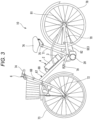
Fig. 3 is a side view of anelectric bicycle 10. -
Fig. 4 is a schematic diagram of a power transmission mechanism T including apower unit 20. -
Fig. 5 is a diagram illustrating electrical paths and communication paths of thepower unit 20, abattery 2, and acontrol circuit 40 in theelectric bicycle 10. -
Fig. 6 is a side view of abattery unit 4. -
Fig. 7 is a cross-sectional view of apedestal 3 of a first embodiment of thebattery unit 4. -
Fig. 8 is a perspective view of a first space SP1 of thepedestal 3 of the first embodiment. -
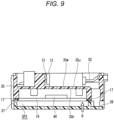
Fig. 9 is a cross-sectional view taken along a P plane ofFig. 8 . -
Fig. 10 is a bottom view of a pedestal body viewed from a direction of an arrow Q inFig. 9 . -
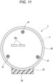
Fig. 11 is a plan view of anupper case 36 of thepedestal 3. -
Fig. 12 is a perspective view of a first space SP1 of apedestal 3 of a second embodiment. -
Fig. 13 is a cross-sectional view of thepedestal 3 of the second embodiment. -
Fig. 14 is a bottom view of a pedestal body as seen from a second space SP2 side. - An electric bicycle will be described below as an example of a vehicle of the present invention. First, with reference to
Fig. 1 , a correlation between parties involved in manufacture of electric bicycles will be described.Fig. 1 assumes that a user who purchased a non-electric bicycle will retrofit the bicycle with an electric assist unit. - Parties involved in manufacture of electric bicycles or the like include a plurality of manufacturers S, A, C, D, and B who manufacture parts for electric assist units or the like, a manufacturer F who manufactures a vehicle body of a non-electric bicycle to which an electric assist unit is attached, a retailer A who sells the vehicle body of the non-electric bicycle, a user (hereinafter also referred to as a user) who purchases the non-electric bicycle from the retailer A, a retailer B who attaches an electric assist unit on the non-electric bicycle in response to a request from the user, a product planner who plans the product of the electric assist unit and coordinates the manufacturers S, A, C, D, and B, an approval authority that determines the conformity of electric assist units to standards, and an enforcement authority that cracks down on illegal vehicles. The correlation between the parties is merely an example, and there may be other parties involved. At least some of the plurality of manufacturers S, A, C, D, and B (in the following description, may be referred to as manufacturers or the like) may be integrated. Manufacturers, users, and product planners may be individuals or corporations, or may be non-corporate associations, foundations, voluntary organizations, and the like.
- The manufacturer F delivers a vehicle body of a non-electric bicycle to the retailer A and receives payment. The retailer A sells the vehicle body of the non-electric bicycle to the user and receives payment.
- The user is a person who purchased and possessed a non-electric bicycle (a non-electric bicycle body) from the retailer A and who wishes to electrify the non-electric bicycle. The user brings the vehicle body of the non-electric bicycle to the retailer B and requests that the non-electric bicycle be electrified. The user pays the price to the retailer B.
- The product planner requests the manufacturers S, A, C, D, and B to manufacture and develop various devices, and pays development and production costs.
- The manufacturer S develops, manufactures, and owns a server. The server collects and stores information on electric bicycles, and performs necessary processing. The server communicates with a control circuit of the electric bicycle or a mobile terminal of the user via a user application to exchange traveling data, or the like. The server communicates with a computer at the retailer B via a store application to exchange traveling data and the like. The server may be a distributed server composed of a plurality of server devices or a distributed virtual server (cloud server) created in a cloud environment.
- The manufacturer A develops an application (application software) to easily manage electric bicycles, provides users with the user application, and provides the retailer B with the store application.
- The manufacturer C develops and manufactures a control circuit with a built-in control program, and delivers the control circuit to the retailer B. The manufacturer D develops and manufactures a power unit (POWER UNIT in
Fig. 1 ) and delivers the power unit to the retailer B. - The manufacturer B develops and manufactures batteries, and delivers the batteries to the retailer B. The manufacturer B may develop and manufacture a battery and a pedestal to which the battery is attached (hereinafter, the battery and pedestal will be collectively referred to as a battery unit), and may deliver the battery unit to the retailer B.
- The retailer B displays and sells electric assist units, control circuits, and batteries at a store, and installs the electric assist units, control circuits, and batteries in appropriate combinations on non-electric bicycles brought in. The retailer B attaches electric assist units and the like to non-electric bicycles and then sells the electric bicycles to users.
- The product planner requests the manufacturers S, A, C, D, and B to manufacture and develop various devices, and also applies for permission for the assist device to the approval authority. The approval authority determines the conformity of the applied assist device to the standards and issues a sticker or the like as proof to the approved and registered product. The approval authority shares approval information with the enforcement authority.
- The enforcement authority is, for example, the police, and cracks down on illegal vehicles based on the approval information provided by the approval authority and the state of the electric bicycle.
- Here, legal regulations imposed on electric bicycles in Japan will be described.
- According to Japanese legal regulations, as illustrated by the solid line in
Fig. 2 , an upper limit of an assist ratio is 2 when vehicle speed is up to 10 [km/h], and it is necessary to gradually reduce the assist ratio from 2 to 0 when the vehicle speed is from 10 [km/h] to 24 [km/h]. Therefore, for example, as illustrated inFig. 2 , the control circuit manufactured by the manufacturer C is programmed to achieve the assist ratio shown by the dashed-dotted line to not exceed the Japanese legal regulations (solid line). In an example shown by the dashed-dotted line inFig. 2 , it is set so that a predetermined margin is secured with respect to the upper limit of the assist ratio in a range of less than 10 [km/h] and a range of 10 [km/h] to 24 [km/h]. - Unlike a completed bicycle in which an assist device is pre-installed, when the assist device is retrofitted, there are many types of vehicle bodies of bicycles to which the assist devices can be attached. Since vehicle body resistance (transmission loss) of a bicycle differs depending on the type, the program built into the control circuit needs to set an appropriate margin. When the margin is not appropriate, a city cycle with a large vehicle body resistance may be compliant with the legal regulations, whereas a sports cycle with a low vehicle body resistance may be non-compliant with the legal regulations. Therefore, the program of the control circuit is preferably initially set based on a bicycle with a small vehicle body resistance value, and may be initially set assuming a bicycle with a minimum loss. When the margin is excessively large, an actual assist ratio will becomes small. Therefore, it is preferable that the retailer B performs fitting by adding an optimization coefficient (correction value) to the program considering a safety factor for each type of the vehicle. The retailer B may perform detailed fitting for each vehicle type without using optimization coefficients (correction values).
- Next, an example of an electric bicycle equipped with a power unit will be described.
- As illustrated in
Fig. 3 , anelectric bicycle 10 is an electric power assist bicycle including afront wheel 73, arear wheel 78, abicycle frame 67, apower unit 20 that drives therear wheel 78, and abattery unit 4 electrically connected to thepower unit 20, and configured to be able to output assist force generated by thepower unit 20. - The
bicycle frame 67 includes ahead pipe 68 at a front end, adown pipe 69 extending rearward and downward from thehead pipe 68 from a front of a vehicle body to the rear, a support pipe 66 (seeFig. 4 ) fixed to a rear end of thedown pipe 69 and extending from side to side, aseat post 71 rising upward from thesupport pipe 66, and a pair of left and rightrear forks 70 extending rearward from thesupport pipe 66. - A
front fork 72 is steerably supported by thehead pipe 68, and thefront wheel 73 is pivotally supported at a lower end of thefront fork 72. Asteering handle bar 74 is provided at an upper end of thefront fork 72. Thesteering handle bar 74 is provided with amobile terminal holder 6 that holds a mobile terminal 8 (seeFig. 5 ) owned by a user. Themobile terminal holder 6 is not essential, and the user'smobile terminal 8 may be attached to (accommodated in) the users themselves or something they wear (clothes, bag). Therear wheel 78 serving as a driving wheel is pivotally supported between rear ends of a pair of left and rightrear forks 70 extending rearward from theseat post 71. Asupport shaft 75 provided with aseat 76 at the upper end is attached to theseat post 71 so that a vertical position of theseat 76 can be adjusted. - The
battery unit 4 that supplies power to thepower unit 20 is detachably fixed to thedown pipe 69. More specifically, thebattery unit 4 includes apedestal 3 attached to an upper surface of thedown pipe 69, and abattery 2 is detachably held on thepedestal 3. Details of thebattery unit 4 will be described below. - A pair of crank
pedals 79 are respectively connected to left and right ends of acrankshaft 83 that coaxially passes through thesupport pipe 66 of thebicycle frame 67. A pedal force applied to thecrank pedal 79 is transmitted to thecrankshaft 83 and input to anendless chain 82 via a drive sprocket 80 (seeFig. 4 ). Thechain 82 is wound around the drivingsprocket 80 and a drivensprocket 81 provided on an axle of therear wheel 78. - Referring also to
Fig. 4 , thepower unit 20 is configured such that a motor M and thecrankshaft 83 are integrated into a unit, and can be retrofitted around thesupport pipe 66 of thebicycle frame 67. That is, thepower unit 20 and thebattery unit 4 are disposed physically (spatially) apart from each other. - In the
power unit 20, anoutput shaft 21 of the motor M and thecrankshaft 83 are arranged in parallel inside a case 24. Thecrankshaft 83 is rotatably supported inside asleeve 26 having a cylindrical shape via a first one-way clutch 28, and a drivengear 26a that meshes with amotor output gear 21a provided on theoutput shaft 21 of the motor M and the drivingsprocket 80 are fixed to an outer peripheral side of thesleeve 26. Therefore, torque of the motor M is transmitted to thedrive sprocket 80 via themotor output gear 21a, the drivengear 26a, and thesleeve 26. That is, the motor M is provided in parallel with thecrank pedal 79. - A second one-way clutch 29 is provided between the driven
sprocket 81 and therear wheel 78. - In the
electric bicycle 10 configured as such, when thecrank pedal 79 is pedaled in a forward direction (also referred to as a forward rotation direction), the first one-way clutch 28 is engaged, and a forward rotational power of thecrankshaft 83 is transmitted to thedrive sprocket 80 via thesleeve 26, and further transmitted to the drivensprocket 81 via thechain 82. Here, the second one-way clutch 29 is also engaged, so that the forward rotational power transmitted to the drivensprocket 81 is transmitted to therear wheel 78. - On the other hand, when the
crank pedal 79 is pedaled in a reverse direction (also referred to as a reverse rotation direction), the first one-way clutch 28 does not engage, and a reverse rotational power of thecrankshaft 83 is not transmitted to thesleeve 26, causing thecrankshaft 83 to idle. - When a forward rotational power in the forward direction (forward rotation direction) is input from the
rear wheel 78, such as when pushing theelectric bicycle 10 forward, the second one-way clutch 29 does not engage, and the forward rotational power of therear wheel 78 is not transmitted to the drivensprocket 81. Therefore, therear wheel 78 rotates relative to the drivensprocket 81. On the other hand, when a reverse rotational power in a rearward direction (reverse rotation direction) is input from therear wheel 78, such as when pushing theelectric bicycle 10 in the rearward direction, the second one-way clutch 29 is engaged and the reverse rotational power of therear wheel 78 is transmitted to the drivensprocket 81 and further transmitted to thedrive sprocket 80 via thechain 82. Since the first one-way clutch 28 is also engaged here, the reverse rotational power transmitted to thedrive sprocket 80 is transmitted to thecrankshaft 83 and crankpedal 79, causing thecrankshaft 83 and crankpedal 79 to rotate in reverse. - The
power unit 20 is provided with a motor rotation speed sensor SE1 that detects the rotation speed of the motor M. Thesleeve 26 is provided with a torque sensor SE2 that detects a torque value generated by a force with which a driver depresses the crank pedal 79 (hereinafter referred to as a pedal depressing force). The motor rotation speed sensor SE1 is composed of a magnet and a Hall IC provided on an outer periphery of theoutput shaft 21 of the motor M. The torque sensor SE2 is composed of a magnetostrictive torque sensor disposed on an outer periphery of thesleeve 26. Therear fork 70 is provided with a rear wheel rotation speed sensor SE3 that obtains the rotation speed of therear wheel 78. Thepower unit 20 is provided with a current sensor and a voltage sensor (not illustrated). - A
control circuit 40 that controls thepower unit 20 is activated by the user operating an application on themobile terminal 8. Thecontrol circuit 40 calculates the force with which the driver depresses the crank pedal 79 (hereinafter referred to as a pedal depressing force) from the torque value that is an output value of the torque sensor SE2, and then thecontrol circuit 40 performs PWM control on the motor M so that an assist force determined by the pedal depressing force and an assist ratio according to the vehicle speed of theelectric bicycle 10 is generated. - In electric bicycles of the related art, the control circuit has generally been incorporated into the electric assist unit. However, in the
electric bicycle 10 of the embodiment, thecontrol circuit 40 is physically (spatially) separated from thepower unit 20 and is incorporated inside thebattery unit 4, more specifically inside thepedestal 3. Although the details will be described below, thepedestal 3 has a first space SP1 therein, and a second space SP2 that is disposed on an opposite side of thebattery 2 with respect to the first space SP1 and is formed to have liquid tightness with respect to the first space SP1. Liquid tightness refers to the property that liquid does not infiltrate from the outside into a sealed space. -
Fig. 5 is a diagram illustrating electrical paths and communication paths of thepower unit 20, thebattery 2, and thecontrol circuit 40 in theelectric bicycle 10. - In the second space SP2 of the
pedestal 3, a control circuit 40 (PROCESSOR in the drawing), a converter DC/DC, an inertial measurement unit IMU, anatmospheric pressure sensor 41, a global navigation satellite system (GNSS)unit 43, amemory 42, and a Bluetooth low energy (BLE)unit 44 are disposed. The electronic components are mounted (fixed) on a circuit board 19 (seeFigs. 7 and9 ). - The
control circuit 40 calculates the torque generated from the motor M of thepower unit 20 so that the assist force determined by the pedal depressing force and the assist ratio according to the vehicle speed of theelectric bicycle 10 is generated as described above. As a result, the motor M operates according to a calculation result (drive request) from thecontrol circuit 40. The converter DC/DC steps down the supplied DC voltage as direct current to generate a power supply voltage for thecontrol circuit 40, the inertial measurement unit IMU, theatmospheric pressure sensor 41, theGNSS unit 43, thememory 42, and theBLE unit 44. InFig. 5 , power lines connecting the converter DC/DC to the inertial measurement device IMU, theatmospheric pressure sensor 41, theGNSS unit 43, thememory 42, and theBLE unit 44 are omitted. - The inertial measurement device IMU is, for example, a 9-axis sensor that has the functions of a 3-axis acceleration sensor, a 3-axis angular velocity sensor, and a 3-axis orientation sensor, and detects the mounting attitude of the
control circuit 40. Theatmospheric pressure sensor 41 detects atmospheric pressure. TheGNSS unit 43 acquires position information of theelectric bicycle 10. The memory is, for example, an SD card, and temporarily or permanently stores information, travel data, and the like of theelectric bicycle 10. TheBLE unit 44 is a communication device for communicating with the user'smobile terminal 8. Thecontrol circuit 40 and the like are disposed in a second space SP2 that is formed in a liquid-tight manner, and water infiltration is avoided even in stormy weather. - In the first space SP1 of the
pedestal 3,male terminals 36a (plugs) electrically connected to female terminals (receptacles) 11 provided on thebattery 2, aplug receptacle pair 12 connected to themale terminals 36a viapower lines 51, anelectrical connector pair 13 electrically connected to thecontrol circuit 40 viapower lines 52 and the converter DC/DC, acommunication connector pair 14 electrically connected to thecontrol circuit 40 via acommunication line 53, and acommunication connector pair 15 communicably connected to thecontrol circuit 40 via acommunication line 54 are provided. - The
plug receptacle pair 12 is detachable from each other, and is connected to thebattery 2 via thepower lines 51 and themale terminals 36a, as well as to thepower unit 20 viapower lines 55. Theelectrical connector pair 13 is connected to the converter DC/DC via thepower lines 52 and to thepower unit 20 viapower lines 56. Thepower lines 56 are configured to be supplied with power from thebattery 2 by branching from thepower lines 55 or the like. Thecommunication connector pair 14 is connected to thecontrol circuit 40 via thecommunication line 53 and to thepower unit 20 via acommunication line 57. Thecommunication connector pair 15 is connected to thecontrol circuit 40 via thecommunication line 54 and to thepower unit 20 via acommunication line 58. A communication method via thecommunication lines - The
electrical connector pair 13, thecommunication connector pair 14, and thecommunication connector pair 15 configure thesame connector pair 16. Thepower lines 52, thecommunication line 53, and thecommunication line 54 configure afirst harness 59, and thepower lines 56, thecommunication line 57, and thecommunication line 58 configure asecond harness 60. As described above, since the connector pairs are integrated by theconnector pair 16, and the power lines and the communication lines are bundled and routed as one, assembly work can be facilitated. - In the electrical system and communication system configured as such, power from the
battery 2 is supplied to the motor M of thepower unit 20, and the power stepped down from thepower unit 20 via the converter DC/DC is supplied to thecontrol circuit 40, the inertial measurement unit IMU, theatmospheric pressure sensor 41, theGNSS unit 43, the memory, and theBLE unit 44. Thecontrol circuit 40 receives the power before being stepped down by the converter DC/DC via apower branch line 52a, and outputs a power switch signal to thepower unit 20 via thecommunication lines control circuit 40 and the user requests activation of thepower unit 20 via the application on themobile terminal 8, a power switch signal is transmitted to thepower unit 20 via thecommunication lines power unit 20 is activated. When thepower unit 20 is activated, information is exchanged between thepower unit 20 and thecontrol circuit 40 via thecommunication lines BLE unit 44. - Next, the configuration of the
battery unit 4 will be described in detail.Fig. 6 is a side view of thebattery unit 4.Fig. 7 is a cross-sectional view of thepedestal 3 of the first embodiment of thebattery unit 4.Fig. 8 is a perspective view of the first space SP1 of thepedestal 3 of the first embodiment.Fig. 9 is a cross-sectional view taken along a plane P inFig. 8 .Fig. 10 is a bottom view of abase body 35 viewed from a direction of an arrow Q inFig. 9 . - As illustrated in
Fig. 6 , thebattery unit 4 includes thepedestal 3 attached to theseat post 71, and thebattery 2 that is detachably attached to thepedestal 3 and includes a plurality of cells inside. Thebattery 2 includes a charging port (receptacle) 46 covered by acover 45 that can be opened and closed on the outer peripheral surface. By connecting a charging terminal (not illustrated) to the chargingport 46, power can be supplied to an external device (for example, the mobile terminal 8). - The
pedestal 3 includes apedestal base 31 that comes into contact with a bottom surface of thebattery 2, apedestal plate 32 that has a plate shape and extends along thedown pipe 69, alocking mechanism 33 capable of locking thepedestal 3 and thebattery 2, and a pedestalupper portion 34 accommodating thelocking mechanism 33 and provided on an upper part of thepedestal plate 32. - As illustrated in
Fig. 7 , thepedestal base 31 includes thebase body 35 having apartition wall 35w that partitions the first space SP1 and the second space SP2, anupper case 36 located above thebase body 35 and forming the first space SP1 between theupper case 36 and thebase body 35, and abottom case 37 located below thebase body 35 and forming the second space SP2 between thebottom case 37 and thebase body 35. In other words, thebase body 35 is provided to form a space on the second space SP2 side of the first space SP1, and theupper case 36 is provided to form a space on an anti-second space SP2 side of the first space SP1. The anti-second space SP2 side means the side opposite to the second space SP2. Thebase body 35 and theupper case 36 are provided to form the first space SP1 side of the second space SP2, and thebottom case 37 is provided to form an anti-first space SP1 side of the second space SP2. The anti-first space SP1 side means the side opposite to the first space SP1. - As illustrated in
Fig. 10 , thebase body 35 includes abody portion 35a having an annular shape, an extendingportion 35c having a substantially rectangular shape and provided in a part of a circumferential direction of thebody portion 35a having an annular shape, and a pair ofear portions 35d provided on the side opposite to the extendingportion 35c. The extendingportion 35c is provided with adrain hole 35e that penetrates vertically and communicates with adrain hole 39 of thebottom case 37, which will be described below. A total of fourfirst fixing portions 35f are provided on the pair ofear portions 35d and theextension portion 35c, and thebottom case 37 is detachably fixed to thebase body 35 by a fastening member (tapping, bolt) (not illustrated) which is fixed to thefirst fixing portion 35f from below. - As illustrated in
Fig. 8 , threesecond fixing portions 35g having a columnar shape are provided at approximately 120° intervals on anupper surface 35u of thepartition wall 35w of thebody portion 35a. Referring also toFig. 11 , theupper case 36 is detachably fixed to thebase body 35 by fastening abolt 47 passing through theupper case 36 to thesecond fixing portion 35g. Thebolt 47 is provided in a position hidden by thebattery 2 attached to thepedestal 3. Therefore, removal of theupper case 36 is prohibited while thebattery 2 is attached to thepedestal 3. Thebolt 47 may be fastened from the first space SP1 side, and then, the bolt hole provided in theupper case 36 is provided in a position hidden by thebattery 2 attached to thepedestal 3. - As illustrated in
Fig. 10 , fourthird fixing portions 35h having a columnar shape are provided at approximately 90° intervals on aback surface 35b of thepartition wall 35w of thebody portion 35a. Referring also toFig. 7 , thecircuit board 19 on which thecontrol circuit 40 and the like are mounted is fixed to thethird fixing portion 35h by a fastening member (tapping, bolt) (not illustrated) to be suspended from thebase body 35. The GNSS unit 43 (not illustrated) is disposed on thecircuit board 19 to be located above thecircuit board 19 in a vertical direction. - As illustrated in
Figs. 7 and9 , the second space SP2 is maintained in a liquid-tight state by aseal member 17 having an annular shape and provided on an outer periphery of theback surface 35b of thebase body 35. The first space SP1 communicates with the outside via thewater draining hole 35e and thedrain hole 39 provided in thebottom case 37, as illustrated inFig. 8 . Thedrain hole 39 is disposed on a fixingsurface 38 of thepedestal 3 fixed to an upper surface of thedown pipe 69. Thereby, it is possible to prevent dust and water from entering the first space SP1 from thedrain hole 39. It is preferable that thedown pipe 69 be provided with an annular projection around the fixing hole to which thepedestal 3 is attached. When there is no annular projection, drainage from thedrain hole 39 is facilitated by interposing a collar therebetween. A diameter of thedrain hole 39 is preferably 4 mm or more. - As illustrated in
Fig. 7 , theupper case 36 is provided with themale terminal 36a on anupper surface 36u, which is electrically connected to thefemale terminal 11 provided on a lower surface of thebattery 2. Themale terminal 36a extends through theupper surface 36u to the first space SP1, and is connected to theplug receptacle pair 12 provided in the first space SP1 via thepower line 51. Themale terminal 36a may not penetrate theupper surface 36u, and thepower line 51 may penetrate theupper surface 36u and be connected to themale terminal 36a. - As illustrated in
Figs. 7 and8 , theplug receptacle pair 12 of a positive electrode side, theplug receptacle pair 12 of a negative electrode side, and theconnector pair 16 are arranged in parallel in the first space SP1. Thepower lines 51 connected to themale terminal 36a extend from one end sides of theplug receptacle pair 12 of the positive electrode side and theplug receptacle pair 12 of the negative electrode side. Thefirst harness 59 extends from one end side of theconnector pair 16 toward the second space SP2. That is, thepower line 51 and thefirst harness 59 are also disposed in the first space SP1. Although the first harness 59 (power line 52,communication lines 53 and 54) and the connector pair 16 (electrical connector pair 13, communication connector pairs 14 and 15) do not necessarily have to go through the first space SP1, the liquid-tightness of the second space SP2 can be better maintained by using a wiring route that goes through the first space SP1. - Two
power lines 55 and thesecond harness 60 extend toward thepower unit 20 from the other ends of theplug receptacle pair 12 of the positive electrode side, theplug receptacle pair 12 of the negative electrode side, and theconnector pair 16. The twopower lines 55 extend toward thepower unit 20 through acommunication hole 30a that communicates the inside and outside of the first space SP1. Theconnector 16 on the motor M side of theconnector pair 16 is disposed in acommunication hole 30b, and thesecond harness 60 extends toward thepower unit 20. The communication holes 30a and 30b are formed by thebase body 35 and theupper case 36. Theplug receptacle 12 on the motor M side of theplug receptacle pair 12 may be disposed in thecommunication hole 30a, and thepower line 55 may extend toward thepower unit 20. Thesecond harness 60 may extend toward thepower unit 20 through thecommunication hole 30b. - The
first harness 59 extends to the second space SP2 through aninsertion hole 35p (seeFig. 10 ) provided in thepartition wall 35w of thebase body 35. Agrommet 18 is interposed between thefirst harness 59 and theinsertion hole 35p, and the second space SP2 is maintained in a liquid-tight state with respect to the first space SP1. InFigs. 7 and9 , only thecontrol circuit 40 is illustrated among the electronic components mounted on thecircuit board 19, and the converter DC/DC, the inertial measurement unit IMU, theatmospheric pressure sensor 41, theGNSS unit 43, the memory, and theBLE unit 44 are not illustrated. - As described above, according to the embodiment, the
control circuit 40 is disposed apart from thepower unit 20, so that thepower unit 20 can be supplied from a plurality of manufacturers. Since thecontrol circuit 40 is disposed inside thebattery unit 4, the internal space of thebattery unit 4 can be effectively utilized. Thecontrol circuit 40 does not need to be disposed inside thebattery unit 4, and may be disposed outside thebattery unit 4 and adjacent to thebattery unit 4. - In the embodiment, since the
control circuit 40 is disposed inside thepedestal 3 that configures thebattery unit 4, the internal space of thepedestal 3 to which thebattery 2 is attached can be effectively utilized. Thecontrol circuit 40 does not need to be disposed inside thepedestal 3 configuring thebattery unit 4, and may be disposed adjacent to thepedestal 3 outside thepedestal 3. - In the embodiment, a part of the
male terminal 36a electrically connected to thefemale terminal 11 provided in thebattery 2 is disposed in the first space SP1, and thecontrol circuit 40 is disposed in the second space SP2. By separating the spaces in which themale terminal 36a and thecontrol circuit 40 are disposed as such, the influence of noise on thecontrol circuit 40 can be reduced. - In the embodiment, the
control circuit 40 is disposed inside thepedestal 3 at a position opposite to thebattery 2 with respect to themale terminal 36a, so that the distance between thefemale terminal 11 and themale terminal 36a can be shortened. Thefemale terminal 11 and themale terminal 36a may be connected wirelessly. That is, the configuration may be such that power is supplied from thefemale terminal 11 provided in thebattery 2 to themale terminal 36a by non-contact discharge. Even then, the short distance between thefemale terminal 11 and themale terminal 36a improves transmission efficiency. - In addition to the
male terminal 36a, theplug receptacle pair 12, theelectrical connector pair 13, thecommunication connector pair 14, and thecommunication connector pair 15 are also disposed in the first space SP1. By consolidating the connector pairs 12 to 15 in the first space SP1 as such, wiring connection work becomes easier. - In the embodiment, the
electrical connector pair 13, thecommunication connector pair 14, and thecommunication connector pair 15 are accommodated in thesame connector pair 16, making the wiring connection work further easier. - In the embodiment, the first space SP1 communicates with the
drain hole 39 that opens to the outside, so that water or the like that enters the first space SP1 can be drained. Therefore, it is possible to prevent theplug receptacle pair 12 or the like from being exposed to water. - In the embodiment, the
control circuit 40 is disposed inside thepedestal 3 configuring thebattery unit 4, and at least a part of thecontrol circuit 40 is disposed at a position overlapping thedown pipe 69 when viewed from below. Thereby, thedown pipe 69 can protect thecontrol circuit 40 from impacts from below due to flying stones or the like. It is preferable that thecontrol circuit 40 be disposed at a position higher than an upper end of thepower unit 20 in the vertical direction. Accordingly, thecontrol circuit 40 can be protected. - Next, the
pedestal 3 of a second embodiment will be described with reference toFigs. 12 to 14 . In the following description, differences from the first embodiment will be mainly described, and descriptions of the similar components will be simplified or omitted. - In the
pedestal 3 of the second embodiment, theear portion 35d is not provided in thebase body 35, and a total of fourfirst fixing portions 35f are provided in thebody portion 35a and the extendingportion 35c. Abolt 48 fixed to thefirst fixing portion 35f is disposed in the first space SP1. That is, thebolt 48 is configured such that thebottom case 37 can be attached by thebolt 48 from the first space SP1 through thefirst fixing portion 35f, and thebolt 48 cannot be attached or removed from the outside. InFig. 13 ,reference numeral 49 denotes a receiving portion that is provided upright on thebottom case 37 and has a female threaded portion into which thebolt 48 is screwed. - Since the
bolt 48 is disposed in the first space SP1 as such, it is necessary to remove theupper case 36 from thebase body 35 when removing thebottom case 37 from thebase body 35. However, as described in the first embodiment, thebolts 47 for fixing theupper case 36 and thebase body 35 are disposed in positions hidden by thebattery 2 attached to thepedestal 3. Thepedestal 3 and thebattery 2 are configured to be lockable by thelocking mechanism 33. Therefore, since a third party cannot easily access the first space SP1 and the second space SP2, mischief and unauthorized modification are prevented. The first space SP1 may be provided with a bolt hole into which thebolt 48 is screwed. - In the embodiment, as illustrated in
Fig. 12 , the two plug receptacle pairs 12 and theconnector pair 16 are disposed in an inclined state with respect to the fixingsurface 38 of thepedestal 3. Thereby, the space in the first space SP1 can be effectively utilized. Theconnector 16 on the motor M side and the twopower lines 55 extending from two plug receptacle pairs 12 pass through onecommunication hole 30c, and thesecond harness 60 and the twopower lines 55 extend toward thepower unit 20. - The
communication hole 30c is formed by thebase body 35 and theupper case 36, which is similar to the first embodiment, but in the embodiment, thecommunication hole 30c is disposed at a different position from the fixingsurface 38 of thepedestal 3 which is fixed to the upper surface of thedown pipe 69. Specifically, thecommunication hole 30c is provided at a constriction on one side between thebody portion 35a having an annular shape and the extendingportion 35c having a substantially rectangular shape, and theconnector 16 on the motor M side and the twopower lines 55 are disposed vertically. As such, by disposing thecommunication hole 30c at a position that avoids the fixingsurface 38, it is possible to avoid interference with thedown pipe 69 by the wiring and the like passing through the communication hole. - In the embodiment, two
drain holes 39 are provided in thebottom case 37. By disposing the drain holes 39 on both left and right sides of the fixingsurface 38, drainage performance is improved. When only onedrain hole 39 is provided, it is preferably provided at a position on the left side of theelectric bicycle 10. Therefore, even when theelectric bicycle 10 is supported on a side stand when theelectric bicycle 10 is not in use, water can be drained from the first space SP1. - Although various embodiments are described above with reference to the drawings, it goes without saying that the present invention is not limited to such examples. It is clear that those skilled in the art can come up with various changes or modifications within the scope of the claims, and it is understood that such changes or modifications also naturally fall within the technical scope of the present invention. Each of the components in the above embodiments may be freely combined without departing from the spirit of the invention.
- The
electric bicycle 10 may be a road bike, a mountain bike, a cross bike, a city cycle, a folding bicycle, or the like, and the type thereof is not limited. Thepedestal 3 of thebattery unit 4 is not limited to the upper surface of thedown pipe 69, but may be fixed at any position such as a lower surface of thedown pipe 69, a front surface of theseat post 71, a rear surface of theseat post 71, and the like. For example, in the case of a road bike, a mountain bike, a cross bike, or the like, thepedestal 3 may be fixed to an upper surface of a top pipe that connects a head pipe and a seat post above a down pipe, or to a lower surface of the top pipe. - In the
electric bicycle 10 in which a body (cover, cowl) is attached to a frame, thepedestal 3 of thebattery unit 4 may be fixed to the body. - In the above-described embodiments, a case is described in which an electric assist unit is retrofitted to a non-electric bicycle after being sold. However, the present invention is not necessarily limited to non-electric bicycles after being sold, but can also be applied to completed bicycles configured by new non-electric bicycles that have been fitted with an electric assist unit at factories or retailers.
- In the embodiments described above, the
power unit 20 drives therear wheel 78, but thepower unit 20 may drive thefront wheel 73. - The
power unit 20 is not limited to the embodiments described above, and may have a simple configuration in which the motor M is accommodated in the case 24, for example. - The electrical paths and communication paths of the
power unit 20, thebattery 2, and thecontrol circuit 40 illustrated inFig. 5 are not limited thereto. In the embodiments described above, the power from thebattery 2 supplied to the converter DC/DC is supplied via thepower unit 20 through thepower line 56, theelectrical connector pair 13, and thepower line 52. However, the power may be supplied from thebattery 2 to the converter DC/DC without passing through thepower unit 20. - The
power unit 20 may also include a processor (microcomputer, motor ECU) as an electric motor control unit, and may control the motor M by communicating with thecontrol circuit 40 via thecommunication lines control circuit 40. The protection of the motor M may be independently controlled by the processor without receiving requests or instructions from thecontrol circuit 40. - Among the
control circuit 40, the converter DC/DC, the inertial measurement unit IMU, theatmospheric pressure sensor 41, theGNSS unit 43, thememory 42, and theBLE unit 44 provided in thepedestal 3, the components other than thecontrol circuit 40, theGNSS unit 43, and theBLE unit 44 may be provided in thepower unit 20. - The specification describes at least the following matters. Although components corresponding to those in the above-described embodiments are shown in parentheses, the present invention is not limited thereto.
- (1) A vehicle (electric bicycle 10) that includes:
- a wheel (rear wheel 78);
- an electric motor (power unit 20) configured to drive the wheel;
- a power storage device (battery unit 4) electrically connected to the electric motor; and
- an arithmetic device (control circuit 40) configured to calculate a command value or a request value that correlates to power generated from the electric motor, where
- the electric motor and the power storage device are disposed apart from each other, and
- the arithmetic device is disposed inside the power storage device or adjacent to the power storage device while being apart from the electric motor.
- According to (1), since it is only necessary to configure the electric motor to operate according to calculation results transmitted from the arithmetic device, it becomes easy to receive supplies of electric motors from a plurality of manufacturers or the like. The arithmetic device can be disposed by effectively utilizing the internal space or the adjacent space of the power storage device.
- "Power" may be torque or output, and may also be a current command, or a current request. "Power" is a concept that includes regenerative power that is negative power in a rotation direction, and reverse power-run power (vehicle rearward movement) that is positive power in a reverse rotation direction in addition to power-run power that is positive power in a forward rotation direction.
- The arithmetic device needs to calculate at least "a command value or a request value that correlates to power generated from the electric motor". The arithmetic device may calculate an output limit value of the motor or an output limit value of the battery, or may perform calculations for control based on the output limit value.
- (2) The vehicle according to (1), where
- the power storage device includes,
- an attachment unit (pedestal 3) fixed to a vehicle body (body) or frame portion (down pipe 69) of the vehicle, and
- a power storage unit (battery 2) that is detachably attached to the attachment unit and includes a power storage element therein, and
- the arithmetic device is disposed inside the attachment unit or adjacent to the attachment unit.
- According to (2), the arithmetic device can be disposed by effectively utilizing the internal space or adjacent space of the attachment unit of the power storage device to which the power storage unit is attached.
- (3) The vehicle according to (2), where
- the arithmetic device is disposed inside the attachment unit,
- the attachment unit includes a second electrical connector (male terminal 36a) electrically connected to a first electrical connector (female terminal 11) that is provided in the power storage unit, and
- the arithmetic device is disposed at a position opposite to the power storage unit with respect to the second electrical connector and inside the attachment unit.
- According to (3), since the distance between the first electrical connector and the second electrical connector can be shortened, the transmission efficiency is improved, for example, when the first electrical connector and the second electrical connector are connected wirelessly.
- (4) The vehicle according to (3), where
- the attachment unit includes,
- a first space (first space SP1) in which the second electrical connector or a power line (power line 51) connected to the second electrical connector is disposed, and
- a second space (second space SP2) partitioned from the first space and formed to have liquid-tightness, and
- the arithmetic device is disposed in the second space.
- According to (4), since the spaces in which the second electrical connector and the arithmetic device are disposed are separated, the influence of noise on the arithmetic device can be reduced.
- (5) The vehicle according to (4), where
the attachment unit includes, - a first portion (
base body 35, upper case 36) provided to form a space on a near side to the first space of the second space, and - a second portion (bottom case 37) detachably fixed to the first portion and provided to form a space on a far side from first space of the second space.
- According to (5), access to the second space becomes easy.
- (6) The vehicle according to (5), where
the arithmetic device is fixed to and disposed in the first portion. - According to (6), the impact on the arithmetic device can be reduced.
- (7) The vehicle according to (5) or (6), where
a fixture (bolt 48) that fixes the first portion and the second portion, or an insertion hole (bolt hole) into which the fixture is inserted, is disposed in the first space. - According to (7), since the fixture cannot be removed from the outside, mischief and unauthorized modification are prevented.
- (8) The vehicle according to any one of (4) to (7), where
the attachment unit includes, - a third portion (base body 35) provided to form a space on a near side to the second space of the first space, and
- a fourth portion (upper case 36) detachably fixed to the third portion and provided to form a space on a far side from the second space of the first space.
- According to (8), access to the first space becomes easy.
- (9) The vehicle according to (8), where
another fixture (bolt 47) that fixes the third portion and the fourth portion, or another insertion hole (bolt hole) into which the another fixture is inserted, is disposed in a position hidden by the power storage unit attached to the attachment unit. - According to (9), removal of the fourth portion is prohibited while the power storage unit is attached to the attachment unit.
- (10) The vehicle according to (9), where
the power storage device includes a lock portion (locking mechanism 33) configured to lock the attachment unit and the power storage unit. - According to (10), it is possible to prevent the power storage unit from being removed from the attachment unit.
- (11) The vehicle according to any one of (4) to (10), where
- the power line is electrically connected to the electric motor and includes an electrical connector pair (plug receptacle pair 12) that is attachable and detachable from each other, and
- the electrical connector pair is disposed in the first space.
- According to (11), the electrical connector pair can be protected.
- (12) The vehicle according to any one of (4) to (11), further including:
- a communication line (communication line 54) communicably connecting the arithmetic device and the electric motor or an electric motor control unit (motor ECU, inverter) that controls the electric motor, where
- the communication line is disposed in the first space.
- According to (12), although it is not necessary for the communication line connecting the arithmetic device and the electric motor to go through the first space, the liquid-tightness of the second space can be further maintained by using a wiring route that goes through the first space.
- (13) The vehicle according to (12), where
- the communication line includes a communication connector pair (communication connector pair 15) that is attachable and detachable from each other, and
- the communication connector pair is disposed in the first space.
- According to (13), although it is not necessary to go through the first space for the communication connector pair, it is possible to further maintain the liquid tightness of the second space by setting the wiring route to go through the first space.
- (14) The vehicle according to (12) or (13), where
- the attachment unit has a partition wall (
partition wall 35w) that partitions the first space and the second space, and - the partition wall has an insertion hole (
insertion hole 35p) through which the communication line is inserted, and a sealing portion (grommet 18) interposed between the insertion hole and the communication line. - According to (14), the liquid tightness of the second space can be ensured.
- (15) The vehicle according to any one of (12) to (14), further including:
- another power line (power line 52) electrically connecting the arithmetic device and the electric motor, where
- the another power line and the communication line are bundled and routed integrally.
- According to (15), assembly work can be facilitated.
- (16) The vehicle according to (15), where
- the communication line includes a communication connector pair (communication connector pair 15) that is attachable and detachable from each other,
- the another power line includes another power connector pair (electrical connector pair 13) that is attachable and detachable from each other, and
- the communication connector pair and the another power connector pair are provided to be integrated when attached.
- According to (16), assembly work can be facilitated.
- (17) The vehicle according to (16) as dependent on (11), where
- the attachment unit is provided with a communication hole (
communication hole - at least one of
- an electrical connector (plug
receptacle 12 on electric motor side) of the electrical connector pair on a near side to the electric motor, or a power line part (power line 55) of the power line that is nearer to the electric motor than the electrical connector pair, and - a communication connector (
connector 16 on motor M side) of the communication connector pair on a near side to the electric motor or the electric motor control unit, or a communication line part (second harness 60) of the communication line that is nearer to the electric motor or the electric motor control unit than the communication connector pair
- an electrical connector (plug
- is disposed in the communication hole.
- According to (17), the first space communicates with the outside through the communication hole.
- (18) The vehicle according to (17), where
the communication hole is disposed at a position away from a fixing surface of the attachment unit that is fixed to the vehicle body or the frame portion. - According to (18), it is possible to avoid interference of the wiring or the like passing through the communication hole with the vehicle body or the frame portion.
- (19) The vehicle according to any one of (4) to (18), where
- the attachment unit includes another communication hole (drain hole 39) communicating inside and outside of the first space, and
- the another communication hole is disposed on a fixing surface (fixing surface 38) of the attachment unit that is fixed to the vehicle body or the frame portion.
- According to (19), it is possible to prevent dust and water from entering the first space from the other communication hole.
- (20) The vehicle according to any one of (2) to (19), where
- the arithmetic device is fixed to a substrate (circuit board 19), and
- the substrate is fixed to the attachment unit.
- According to (20), the arithmetic device can be protected.
- (21) The vehicle according to (20), further including:
- a receiver (GNSS unit 43) of a satellite positioning system, where
- the receiver is fixed to the substrate, and
- the substrate is disposed such that the receiver is located higher than the substrate in a vertical direction.
- According to (21), it is possible to protect the receiver of the satellite positioning system while preventing a decline in reception capability.
- (22) The vehicle according to (20) or (21), further including:
- a communication portion (BLE unit 44) capable of wirelessly communicating with a terminal that is attached to the vehicle or carried by a passenger of the vehicle, where
- the communication portion is fixed to the substrate.
- According to (22), the communication portion can be protected.
- (23) The vehicle according to any one of (1) to (22), where
- the electric motor is accommodated in a casing (case 24) together with a power transmission portion (
motor output gear 21a, drivengear 26a) mechanically connected to the electric motor, and - the arithmetic device is disposed inside the power storage device or adjacent to the power storage device while being apart from the casing.
- According to (23), it becomes easy to receive supplies of power units in which an electric motor and a power transmission portion are integrated from a plurality of manufacturers.
- (24) The vehicle according to any one of (1) to (23), where
at least a part of the arithmetic device is disposed at a position overlapping a frame portion (down pipe 69) of the vehicle when viewed from a vertically downward side. - According to (24), the frame portion of the vehicle can protect the arithmetic device from impacts from below caused by flying stones or the like.
- (25) The vehicle according to any one of (1) to (24), where
the arithmetic device is disposed at a position higher than an upper end of the electric motor in a vertical direction. - According to (25), the arithmetic device can be protected by the electric motor.
- The application is based on a Japanese patent application (
Japanese Patent Application No. 2021 - 142751) filed on September 1, 2021 -
- 2: battery (power storage unit)
- 3: pedestal (attachment unit)
- 4: battery unit (power storage device)
- 10: electric bicycle (vehicle)
- 11: female terminal (first electrical connector)
- 12: plug receptacle, plug receptacle pair (electrical connector, electrical connector pair)
- 13: electrical connector, electrical connector pair (another electrical connector, another power connector pair)
- 15: communication connector, communication connector pair
- 16: connector (connection member)
- 18: grommet (sealing portion)
- 19: circuit board (substrate)
- 20: power unit (electric motor)
- 21a: motor output gear (power transmission portion)
- 24: case (casing)
- 26a: driven gear (power transmission portion)
- 30a: communication hole
- 30b: communication hole
- 30c: communication hole
- 33: locking mechanism (lock portion)
- 35: base body (third portion)
- 35p: insertion hole (insertion hole)
- 35w: partition wall
- 36: upper case (fourth portion)
- 36a: male terminal (second electrical connector)
- 37: bottom case (second portion)
- 38: fixing surface
- 39: drain hole (communicating hole)
- 40: control circuit (arithmetic device)
- 43: GNSS unit (receiver)
- 44: BLE unit (communication portion)
- 47: bolt (fixture)
- 48: bolt (fixture)
- 51: power line
- 52: power line (another power line)
- 54: communication line
- 55: power line (power line part)
- 60: second harness (communication line part)
- 69: down pipe (frame portion)
- 78: rear wheel (wheel)
- SP1: first space
- SP2: second space
Claims (25)
- A vehicle comprising:a wheel;an electric motor configured to drive the wheel;a power storage device electrically connected to the electric motor; andan arithmetic device configured to calculate a command value or a request value that correlates to power generated from the electric motor, whereinthe electric motor and the power storage device are disposed apart from each other, andthe arithmetic device is disposed inside the power storage device or adjacent to the power storage device while being apart from the electric motor.
- The vehicle according to claim 1, whereinthe power storage device includes,an attachment unit fixed to a vehicle body or frame portion of the vehicle, anda power storage unit that is detachably attached to the attachment unit and includes a power storage element therein, andthe arithmetic device is disposed inside the attachment unit or adjacent to the attachment unit.
- The vehicle according to claim 2, whereinthe arithmetic device is disposed inside the attachment unit,the attachment unit includes a second electrical connector electrically connected to a first electrical connector that is provided in the power storage unit, andthe arithmetic device is disposed at a position opposite to the power storage unit with respect to the second electrical connector and inside the attachment unit.
- The vehicle according to claim 3, whereinthe attachment unit includes,a first space in which the second electrical connector or a power line connected to the second electrical connector is disposed, anda second space partitioned from the first space and formed to have liquid-tightness, andthe arithmetic device is disposed in the second space.
- The vehicle according to claim 4, wherein
the attachment unit includes,a first portion provided to form a space on a near side to the first space of the second space, anda second portion detachably fixed to the first portion and provided to form a space on a far side from the first space of the second space. - The vehicle according to claim 5, wherein
the arithmetic device is fixed to and disposed in the first portion. - The vehicle according to claim 5 or 6, wherein
a fixture that fixes the first portion and the second portion, or an insertion hole into which the fixture is inserted, is disposed in the first space. - The vehicle according to any one of claims 4 to 7, wherein
the attachment unit includes,a third portion provided to form a space on a near side to the second space of the first space, anda fourth portion detachably fixed to the third portion and provided to form a space on a far side from the second space of the first space. - The vehicle according to claim 8, wherein
another fixture that fixes the third portion and the fourth portion, or another insertion hole into which the another fixture is inserted, is disposed in a position hidden by the power storage unit attached to the attachment unit. - The vehicle according to claim 9, wherein
the power storage device includes a lock portion configured to lock the attachment unit and the power storage unit. - The vehicle according to any one of claims 4 to 10, whereinthe power line is electrically connected to the electric motor and includes an electrical connector pair that is attachable and detachable from each other, andthe electrical connector pair is disposed in the first space.
- The vehicle according to any one of claims 4 to 11, further comprising:a communication line communicably connecting the arithmetic device and the electric motor or an electric motor control unit that controls the electric motor, whereinthe communication line is disposed in the first space.
- The vehicle according to claim 12, whereinthe communication line includes a communication connector pair that is attachable and detachable from each other, andthe communication connector pair is disposed in the first space.
- The vehicle according to claim 12 or 13, whereinthe attachment unit has a partition wall that partitions the first space and the second space, andthe partition wall has an insertion hole through which the communication line is inserted, and a sealing portion interposed between the insertion hole and the communication line.
- The vehicle according to any one of claims 12 to 14, further comprising:another power line electrically connecting the arithmetic device and the electric motor, whereinthe another power line and the communication line are bundled and routed integrally.
- The vehicle according to claim 15, whereinthe communication line includes a communication connector pair that is attachable and detachable from each other,the another power line includes another power connector pair that is attachable and detachable from each other, andthe communication connector pair and the another power connector pair are provided to be integrated when attached.
- The vehicle according to claim 16 as dependent on claim 11, whereinthe attachment unit is provided with a communication hole communicating inside and outside of the first space, andat least one ofan electrical connector of the electrical connector pair on a near side to the electric motor, or a power line part of the power line that is nearer to the electric motor than the electrical connector pair, anda communication connector of the communication connector pair on a near side to the electric motor or the electric motor control unit, or a communication line part of the communication line that is nearer to the electric motor or the electric motor control unit than the communication connector pairis disposed in the communication hole.
- The vehicle according to claim 17, wherein
the communication hole is disposed at a position away from a fixing surface of the attachment unit that is fixed to the vehicle body or the frame portion. - The vehicle according to any one of claims 4 to 18, whereinthe attachment unit includes another communication hole communicating inside and outside of the first space, andthe another communication hole is disposed on a fixing surface of the attachment unit that is fixed to the vehicle body or the frame portion.
- The vehicle according to any one of claims 2 to 19, whereinthe arithmetic device is fixed to a substrate, andthe substrate is fixed to the attachment unit.
- The vehicle according to claim 20, further comprising:a receiver of a satellite positioning system, whereinthe receiver is fixed to the substrate, andthe substrate is disposed such that the receiver is located higher than the substrate in a vertical direction.
- The vehicle according to claim 20 or 21, further comprising:a communication portion capable of wirelessly communicating with a terminal that is attached to the vehicle or carried by a passenger of the vehicle, whereinthe communication portion is fixed to the substrate.
- The vehicle according to any one of claims 1 to 22, whereinthe electric motor is accommodated in a casing together with a power transmission portion mechanically connected to the electric motor, andthe arithmetic device is disposed inside the power storage device or adjacent to the power storage device while being apart from the casing.
- The vehicle according to any one of claims 1 to 23, wherein
at least a part of the arithmetic device is disposed at a position overlapping a frame portion of the vehicle when viewed from a vertically downward side. - The vehicle according to any one of claims 1 to 24, wherein
the arithmetic device is disposed at a position higher than an upper end of the electric motor in a vertical direction.
Applications Claiming Priority (2)
| Application Number | Priority Date | Filing Date | Title |
|---|---|---|---|
| JP2021142751 | 2021-09-01 | ||
| PCT/JP2022/032822 WO2023033061A1 (en) | 2021-09-01 | 2022-08-31 | Vehicle |
Publications (2)
| Publication Number | Publication Date |
|---|---|
| EP4397583A1 true EP4397583A1 (en) | 2024-07-10 |
| EP4397583A4 EP4397583A4 (en) | 2025-10-08 |
Family
ID=85411371
Family Applications (1)
| Application Number | Title | Priority Date | Filing Date |
|---|---|---|---|
| EP22864643.6A Pending EP4397583A4 (en) | 2021-09-01 | 2022-08-31 | VEHICLE |
Country Status (4)
| Country | Link |
|---|---|
| US (1) | US20250121909A1 (en) |
| EP (1) | EP4397583A4 (en) |
| JP (1) | JPWO2023033061A1 (en) |
| WO (1) | WO2023033061A1 (en) |
Family Cites Families (8)
| Publication number | Priority date | Publication date | Assignee | Title |
|---|---|---|---|---|
| JP4189936B2 (en) | 1999-05-25 | 2008-12-03 | 本田技研工業株式会社 | Electric assist bicycle |
| JP2002145147A (en) * | 2000-11-09 | 2002-05-22 | Yamaha Motor Co Ltd | Electric assisted bicycle |
| US8893837B2 (en) * | 2011-06-14 | 2014-11-25 | Samsung Sdi Co., Ltd. | Battery pack storing device and electric vehicle including the same |
| JP5183832B1 (en) * | 2012-06-29 | 2013-04-17 | パナソニック株式会社 | Battery mounting device and electric bicycle |
| JP6034351B2 (en) * | 2014-10-03 | 2016-11-30 | 株式会社シマノ | Bicycle power control device |
| JP7194905B2 (en) * | 2018-01-19 | 2022-12-23 | パナソニックIpマネジメント株式会社 | Electric bicycle and its control method |
| BR112022004243A2 (en) * | 2019-09-11 | 2022-05-31 | Honda Motor Co Ltd | Vehicle and method for monitoring power transmission mechanism abnormality |
| JP2021142751A (en) | 2020-03-11 | 2021-09-24 | 大日本印刷株式会社 | Decorative sheet and decorative plate |
-
2022
- 2022-08-31 EP EP22864643.6A patent/EP4397583A4/en active Pending
- 2022-08-31 US US18/688,365 patent/US20250121909A1/en active Pending
- 2022-08-31 JP JP2023545651A patent/JPWO2023033061A1/ja active Pending
- 2022-08-31 WO PCT/JP2022/032822 patent/WO2023033061A1/en not_active Ceased
Also Published As
| Publication number | Publication date |
|---|---|
| JPWO2023033061A1 (en) | 2023-03-09 |
| US20250121909A1 (en) | 2025-04-17 |
| EP4397583A4 (en) | 2025-10-08 |
| WO2023033061A1 (en) | 2023-03-09 |
Similar Documents
| Publication | Publication Date | Title |
|---|---|---|
| CN103764490B (en) | Straddle-type vehicle | |
| TWI468316B (en) | Electric locomotive | |
| US8854196B2 (en) | Vehicle approach notification apparatus for electric motorcycle | |
| CN103874624A (en) | Electric vehicle | |
| EP3536531B1 (en) | Straddled vehicle | |
| CN103287530B (en) | The arrangement of the voltage changer of the portable information terminal in Straddle-type vehicle | |
| JP2000313383A (en) | Arrangement structure of power supply socket for saddle type four-wheeled vehicle | |
| EP3778362A1 (en) | Usb terminal unit structure for saddle riding-type vehicle | |
| CN217260440U (en) | vehicle | |
| EP4397583A1 (en) | Vehicle | |
| US20180162475A1 (en) | Cycling record system | |
| JP6989637B2 (en) | Harness connection structure | |
| WO2019187798A1 (en) | Usb terminal unit arrangement structure for saddle riding-type vehicle | |
| JPWO2019187791A1 (en) | USB terminal unit structure for saddle-riding vehicles | |
| ES2857950T3 (en) | Motorized vehicle comprising a connected steering column | |
| CN111391953A (en) | Electric vehicle control equipment | |
| JP5235177B2 (en) | Motorcycle | |
| JP7064622B2 (en) | Saddle-type vehicle | |
| EP3778360B1 (en) | Usb terminal unit arrangement structure for saddle riding-type vehicle | |
| JP5667929B2 (en) | Motorcycle | |
| JPWO2020129644A1 (en) | Saddle-type vehicle | |
| JP7770443B2 (en) | Saddle-type vehicle | |
| JP7190510B2 (en) | straddle-type vehicle | |
| TWM427344U (en) | Battery hiding structure of electric bicycle | |
| JP2024041651A (en) | Information processing device, management method, management program, and storage medium |
Legal Events
| Date | Code | Title | Description |
|---|---|---|---|
| STAA | Information on the status of an ep patent application or granted ep patent |
Free format text: STATUS: THE INTERNATIONAL PUBLICATION HAS BEEN MADE |
|
| PUAI | Public reference made under article 153(3) epc to a published international application that has entered the european phase |
Free format text: ORIGINAL CODE: 0009012 |
|
| STAA | Information on the status of an ep patent application or granted ep patent |
Free format text: STATUS: REQUEST FOR EXAMINATION WAS MADE |
|
| 17P | Request for examination filed |
Effective date: 20240229 |
|
| AK | Designated contracting states |
Kind code of ref document: A1 Designated state(s): AL AT BE BG CH CY CZ DE DK EE ES FI FR GB GR HR HU IE IS IT LI LT LU LV MC MK MT NL NO PL PT RO RS SE SI SK SM TR |
|
| DAV | Request for validation of the european patent (deleted) | ||
| DAX | Request for extension of the european patent (deleted) | ||
| RAP3 | Party data changed (applicant data changed or rights of an application transferred) |
Owner name: HONDA MOTOR CO., LTD. |
|
| A4 | Supplementary search report drawn up and despatched |
Effective date: 20250908 |
|
| RIC1 | Information provided on ipc code assigned before grant |
Ipc: B62M 6/45 20100101AFI20250902BHEP Ipc: B62J 45/00 20200101ALI20250902BHEP Ipc: B60K 1/00 20060101ALI20250902BHEP Ipc: B60L 50/53 20190101ALI20250902BHEP Ipc: B60L 50/60 20190101ALI20250902BHEP Ipc: B60L 53/80 20190101ALI20250902BHEP Ipc: B60S 5/06 20190101ALI20250902BHEP Ipc: B62M 6/40 20100101ALI20250902BHEP Ipc: B62M 6/90 20100101ALI20250902BHEP Ipc: B62J 43/23 20200101ALI20250902BHEP Ipc: B62M 6/55 20100101ALI20250902BHEP Ipc: B62J 43/16 20200101ALI20250902BHEP Ipc: B62J 43/20 20200101ALI20250902BHEP |