EP4397581A1 - Storage box for straddled vehicle - Google Patents
Storage box for straddled vehicle Download PDFInfo
- Publication number
- EP4397581A1 EP4397581A1 EP23213604.4A EP23213604A EP4397581A1 EP 4397581 A1 EP4397581 A1 EP 4397581A1 EP 23213604 A EP23213604 A EP 23213604A EP 4397581 A1 EP4397581 A1 EP 4397581A1
- Authority
- EP
- European Patent Office
- Prior art keywords
- vehicle
- information terminal
- portable information
- storage box
- storage
- Prior art date
- Legal status (The legal status is an assumption and is not a legal conclusion. Google has not performed a legal analysis and makes no representation as to the accuracy of the status listed.)
- Granted
Links
Images





Classifications
-
- B—PERFORMING OPERATIONS; TRANSPORTING
- B62—LAND VEHICLES FOR TRAVELLING OTHERWISE THAN ON RAILS
- B62J—CYCLE SADDLES OR SEATS; AUXILIARY DEVICES OR ACCESSORIES SPECIALLY ADAPTED TO CYCLES AND NOT OTHERWISE PROVIDED FOR, e.g. ARTICLE CARRIERS OR CYCLE PROTECTORS
- B62J9/00—Containers specially adapted for cycles, e.g. panniers or saddle bags
- B62J9/10—Containers specially adapted for cycles, e.g. panniers or saddle bags integrated with the cycle
- B62J9/12—Containers specially adapted for cycles, e.g. panniers or saddle bags integrated with the cycle in the fairing
-
- B—PERFORMING OPERATIONS; TRANSPORTING
- B62—LAND VEHICLES FOR TRAVELLING OTHERWISE THAN ON RAILS
- B62J—CYCLE SADDLES OR SEATS; AUXILIARY DEVICES OR ACCESSORIES SPECIALLY ADAPTED TO CYCLES AND NOT OTHERWISE PROVIDED FOR, e.g. ARTICLE CARRIERS OR CYCLE PROTECTORS
- B62J9/00—Containers specially adapted for cycles, e.g. panniers or saddle bags
- B62J9/10—Containers specially adapted for cycles, e.g. panniers or saddle bags integrated with the cycle
-
- B—PERFORMING OPERATIONS; TRANSPORTING
- B62—LAND VEHICLES FOR TRAVELLING OTHERWISE THAN ON RAILS
- B62J—CYCLE SADDLES OR SEATS; AUXILIARY DEVICES OR ACCESSORIES SPECIALLY ADAPTED TO CYCLES AND NOT OTHERWISE PROVIDED FOR, e.g. ARTICLE CARRIERS OR CYCLE PROTECTORS
- B62J17/00—Weather guards for riders; Fairings or stream-lining parts not otherwise provided for
-
- B—PERFORMING OPERATIONS; TRANSPORTING
- B62—LAND VEHICLES FOR TRAVELLING OTHERWISE THAN ON RAILS
- B62K—CYCLES; CYCLE FRAMES; CYCLE STEERING DEVICES; RIDER-OPERATED TERMINAL CONTROLS SPECIALLY ADAPTED FOR CYCLES; CYCLE AXLE SUSPENSIONS; CYCLE SIDECARS, FORECARS, OR THE LIKE
- B62K11/00—Motorcycles, engine-assisted cycles or motor scooters with one or two wheels
- B62K11/02—Frames
- B62K11/04—Frames characterised by the engine being between front and rear wheels
Definitions
- the storage box is capable of storing an electronic device such as a portable information terminal.
- the portable information terminal When stored in the storage box of the straddled vehicle, the portable information terminal is likely to be affected by ground conditions and acceleration of the vehicle due to a lightweight feature of the straddled vehicle. Because of this, it is preferable to retain the portable information terminal inside the storage box. However, when it is assumed to store the portable information terminal in the storage box and then attach a band to the storage box as a structure for retaining the portable information terminal, attaching the band to the portable information terminal is bothersome.
- a storage box for a straddled vehicle stores a portable information terminal.
- the storage box includes a storage portion, a lid portion, at least one elastic member, and a shaft portion.
- the storage portion includes an opening for putting-in and taking-out of the portable information terminal, an inner sidewall, and at least one restriction portion opposed to the inner sidewall.
- the storage portion stores the portable information terminal such that the portable information terminal stands between the inner sidewall and the at least one restriction portion.
- the lid portion is capable of transitioning to a closed state and an opened state. The lid portion closes the opening in the closed state and opens the opening in the opened state. The lid portion is opposed to the inner sidewall in the closed state.
- the at least one elastic member is disposed on at least either the lid portion or the inner sidewall and presses the portable information terminal in a thickness direction of the portable information terminal between the lid portion or the inner sidewall in the closed state to hold the portable information terminal in the storage portion.
- the shaft portion pivotably supports the lid portion.
- the inner sidewall extends in approximately a vehicle up-and-down direction or extends to gradually approach the at least one restriction portion from below to above.
- the inner sidewall and the at least one restriction portion produce a space therebetween so as to allow the portable information terminal to tilt toward the at least one restriction portion in the opened state of the lid portion.
- the at least one restriction portion is apart from the portable information terminal in the closed state and contacts with the portable information terminal on a front or rear surface side of the portable information terminal so as to restrict movement of the portable information terminal when the lid portion transitions from the closed state to the opened state.
- the portable information terminal is stored to stand between the inner sidewall and the at least one restriction portion; besides, the inner sidewall and the at least one restriction portion produce the space therebetween so as to allow the portable information terminal to tilt toward the at least one restriction portion when the lid portion is opened. Because of this, when the rider is riding on the vehicle, for instance, it is made easy for the rider to pubtake the portable information terminal in/out of the storage portion.
- the at least one elastic member may include a first elastic member disposed on the lid portion and a second elastic member disposed on the inner sidewall of the storage portion.
- the portable information terminal when the lid portion is opened while the portable information terminal is stored in the storage portion, the portable information terminal can be supported by the first elastic member until contacting with the at least one restriction portion.
- transference of vibration from the vehicle to the portable information terminal can be effectively inhibited by the first and second elastic members.
- the storage portion may further include a bottom surface portion extending in a direction intersecting with the vehicle up-and-down direction.
- the at least one restriction portion may include a first restriction portion extending upward from the bottom surface portion and a second restriction portion disposed apart from the first restriction portion in the vehicle back-and-forth direction. In this case, movement of the potable information terminal can be stably restricted.
- the storage portion may be disposed forward of a seat of the straddled vehicle, and may be fixed to a member configured not to be turned together with a steering device of the straddled vehicle.
- the portable information terminal stored in the storage box can be easily retained, while the vehicle can be kept in balance. Besides, the portable information terminal is unlikely to be affected by turning of the steering device.
- the storage portion may be disposed lateral to a steering device of the straddled vehicle. In this case, when the rider is riding on the vehicle, the portable information terminal stored in the storage box can be easily retained, while the vehicle can be kept in balance.
- the shaft portion may be disposed below the storage portion. In this case, when opened and closed, the lid portion can be moved upward by as limited an amount as possible.
- the storage box may further include a lid cover fixed to the lid portion outside the lid portion so as to be unitarily pivotable therewith.
- the lid cover may be disposed to form part of an exterior cover of the straddled vehicle. In this case, the storage box is unlikely to be recognized by a third party.
- the storage portion can be enhanced in anti-crime performance; simultaneously, the vehicle can be enhanced in external aesthetics.
- the lid portion can be protected by the lid cover.
- the opening may be opened upward and outward in a vehicle width direction. In this case, it is made easy to pubtake the portable information terminal in/out of the storage portion.
- FIG. 1 is a side view of a straddled vehicle 1 including a storage box 30 according to the preferred embodiment.
- FIG. 2 is a front view of the straddled vehicle 1.
- a right-and-left direction is synonymous with a vehicle width direction.
- the term “outer side in a vehicle width direction” means a side far from the center of the straddled vehicle 1 in the vehicle width direction.
- the term “inner side in the vehicle width direction” means a side near to the center of the straddled vehicle 1 in the vehicle width direction.
- the direction closer to the vehicle back-and-forth direction refers to, for instance, a direction that forms angles, the smaller of which is 45 degrees or less, together with the vehicle back-and-forth direction.
- the settings herein described are also true of the vehicle width direction (rightward and/or leftward directions) and the vehicle up-and-down direction (upward and/or downward directions).
- the vehicle body frame 2 includes a head pipe 11, a main frame 12, and a rear frame 13.
- the main frame 12 is connected to the head pipe 11.
- the main frame 12 extends rearward from the head pipe 11.
- the rear frame 13 is connected to the main frame 12.
- the rear frame 13 extends rearward from the main frame 12.
- the seat 5 is disposed behind the tank-like member 4.
- the seat 5 is disposed above the rear frame 13.
- the rear wheel 8 is supported by the main frame 12 through a swing arm 9 supported by the main frame 12.
- the rear wheel 8 is supported by the swing arm 9 so as to be rotatable.
- the rear wheel 8 is driven by the drive force generated by the power unit 6.
- the straddled vehicle 1 includes a wind shield 20, a front cowl 21, a right side cowl 22, a left side cowl 23, a right side cover 25 (exemplary exterior cover), and a left side cover 26.
- the wind shield 20 is disposed above the front cowl 21.
- the left side cover 26 is connected to the left side cowl 23.
- the left side cover 26 is disposed above the left side cowl 23.
- the left side cover 26 is disposed not only lateral to the steering device 3 but also on the other side of the head pipe 11 in the vehicle width direction.
- the left side cover 26 is disposed on the left of the head pipe 11.
- the left side cover 26 overlaps with the head pipe 11 in the vehicle side view.
- the left side cover 26 is remote from the steering device 3 in the vehicle width direction.
- the left side cover 26 is disposed on the left of the steering device 3.
- the left side cover 26 overlaps with the steering shaft 14 of the steering device 3 in the vehicle side view.
- the storage box 30 is disposed on the right of the steering device 3.
- the storage box 30 overlaps with the steering shaft 14 of the steering device 3 in the vehicle side view.
- the storage box 30 is disposed further on the upper side than the lower bracket 19.
- the storage box 30 is disposed inside the right side cover 25.
- the storage box 30 is disposed further on the front side than the tank-like member 4.
- the storage box 30 does not overlap with the tank-like member 4 in the vehicle side view.
- the storage box 30 overlaps with the tank-like member 4 in the vehicle front view.
- the storage portion 31 is disposed on the right of the steering device 3.
- the storage portion 31 is fixed to a member configured not to be turned together with the steering device 3.
- the storage portion 31 is fixed to the right side cover 25.
- the dimension of the storage portion 31 is greater in the vehicle back-and-forth direction than not only in the vehicle up-and-down direction but also in the vehicle width direction.
- the dimension of the storage portion 31 is greater in the vehicle up-and-down direction than in the vehicle width direction.
- the opening 41 serves as an opening for putting-in and taking-out of the portable information terminal T and is opened not only upward but also outward in the vehicle width direction.
- the opening 41 is defined by the inner sidewall 43, the front surface portion 44, and the rear surface portion 45.
- the storage portion 31 is uncovered upward.
- the storage portion 31 is uncovered outward in the vehicle width direction except for at the restriction portion (or portions) 46.
- an opened state whereas the state that the lid portion 32 is closed will be referred to as "a closed state”.
- the opened state means that the opening 41 is opened (uncovered)
- the closed state means that the opening 41 is closed (covered).
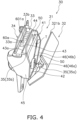
- FIG. 4 shows the opened state
- FIG. 5 shows the closed state.
- the inner sidewall 43 extends in a direction intersecting with the vehicle width direction.
- the inner sidewall 43 extends in approximately both the vehicle up-and-down direction and the vehicle back-and-forth direction.
- the inner sidewall 43 is disposed between the front surface portion 44 and the rear surface portion 45 in the vehicle back-and-forth direction.
- the inner sidewall 43 is connected to the bottom surface portion 42, the front surface portion 44, and the rear surface portion 45.
- the inner sidewall 43 extends upward from a vehicle width directionally inner portion of the bottom surface portion 42.
- the inner sidewall 43 extends to gradually approach to the head pipe 11 from rear to front.
- the front end of the inner sidewall 43 is located further on the inner side than the rear end thereof in the vehicle width direction. In the closed state, the inner sidewall 43 is opposed to the lid portion 32 in the vehicle width direction.
- the rear surface portion 45 extends in a direction intersecting with the vehicle back-and-forth direction.
- the rear surface portion 45 is opposed to the front surface portion 44 in the vehicle back-and-forth direction.
- the rear surface portion 45 extends upward from the rear end of the bottom surface portion 42.
- the rear surface portion 45 extends outward from the rear end of the inner sidewall 43 in the vehicle width direction.
- the rear surface portion 45 is located further on the rear side than the head pipe 11.
- the rear surface portion 45 is located further on the front side than the rear end of the right side cover 25.
- the rear surface portion 45 is disposed further on the rear side than the restriction portion (or portions) 46.
- the rear surface portion 45 defines part of the opening 41.
- the rear surface portion 45 includes an edge 45a extending not only downward but also outward in the vehicle width direction.
- the edge 45a is disposed on the upper end of a vehicle width directionally outer portion of the rear surface portion 45.
- the edge 45a defines part of the opening 41.
- the storage portion 31 stores the portable information terminal T such that the portable information terminal T stands between the inner sidewall 43 and the restriction portion (or portions) 46.
- the standing state of the portable information terminal T means that a lateral surface of the portable information terminal T is put on the bottom surface portion 42.
- the storage portion 31 stores the portable information terminal T such that a width directional lateral surface of the portable information terminal T is put on the bottom surface portion 42.
- the storage portion 31 may be configured to store the portable information terminal T such that a lengthwise directional lateral surface of the portable information terminal T is put on the bottom surface portion 42.
- the restriction portion (or portions) 46 is remote from the portable information terminal T in the closed state.
- the restriction portion (or portions) 46 contacts with the portable information terminal T on the front or rear surface side of the portable information terminal T so as to restrict movement of the portable information terminal T.
- the portable information terminal T tilts toward the restriction portion (or portions) 46 due to a recoil caused in releasing the pressing force applied by the elastic member (or members) 35 and is thereby moved to the restriction portion (or portions) 46.
- the first restriction portion (or portions) 46a is disposed further on the outer side than the inner sidewall 43 in the vehicle width direction.
- the restriction portion (or portions) 46 is opposed to the inner sidewall 43 in the vehicle width direction.
- the dimension of the restriction portion (or portions) 46 is preferably greater than or equal to a quarter of, and less than or equal to three quarters of, that of the inner sidewall 43 in the vehicle up-and-down direction.
- the dimension of the restriction portion (or portions) 46 is preferably less than that of the storage portion 31 in the vehicle back-and-forth direction.
- the attachment portion 47 serves as a portion for attaching a power supply device (not shown in the drawings).
- the power supply device is, for instance, a power socket provided as an accessory socket.
- the power supply device may connect therethrough the portable information terminal T and an electronic device installed in the straddled vehicle 1 such that intercommunication of data is enabled between the portable information terminal T and the electronic device.
- the attachment portion 47 is formed by bulging a rear portion of the inner sidewall 43 inward in the vehicle width direction.
- the attachment portion 47 includes an attachment hole 47a to which the power supply device is attached.
- the attachment hole 47a is disposed further on the inner side than the bottom surface portion 42 in the vehicle width direction.
- the attachment hole 47a is disposed below the upper surface portion 33.
- the engaged portion 32c is provided on the lower surface of the distal end portion 321b of the canopy portion 32b.
- the engaged portion 32c extends downward from the lower surface of the distal end portion 321b of the canopy portion 32b.
- the engaged portion 32c is shaped to recess from the inner side to the outer side in the vehicle width direction.
- the upper surface portion 33 extends in a direction intersecting with the vehicle up-and-down direction.
- the upper surface portion 33 extends from the storage portion 31 in a direction of closing the lid portion 32.
- the upper surface portion 33 extends inward from the storage portion 31 in the vehicle width direction.
- the upper surface portion 33 extends inward from the inner sidewall 43 in the vehicle width direction.
- the upper surface portion 33 is disposed further on the lower side than the aforementioned upper end (43a) of the inner sidewall 43.
- the upper end 43a of the inner sidewall 43 protrudes further upward than the upper surface portion 33. Because of this, a step is provided between the upper surface portion 33 and the inner sidewall 43. In the closed state, the upper surface portion 33 is disposed below the canopy portion 32b so as to be covered therewith.
- the upper surface portion 33 includes a through hole 33a and a plurality of drain holes 33b.
- the through hole 33a and the plural drain holes 33b are disposed between the opposed portion 34 and the storage portion 31.
- the through hole 33a and the plural drain holes 33b are disposed between the opposed portion 34 and the inner sidewall 43.
- the through hole 33a and the plural drain holes 33b penetrate the upper surface portion 33 in the vehicle up-and-down direction.
- the through hole 33a is provided in the vicinity of the middle of the upper surface portion 33 in the vehicle back-and-forth direction.
- the plural drain holes 33b are provided on the front side and the rear side of the through hole 33a.
- the opposed portion 34 is connected to the upper surface portion 33.
- the opposed portion 34 extends upward from the upper surface portion 33.
- the opposed portion 34 is disposed further on the inner side than the plural drain holes 33b in the vehicle width direction.
- the opposed portion 34 is opposed to the distal end portion 321b of the canopy portion 32b.
- a seal member 40 is disposed between the opposed portion 34 and the distal end portion 321b of the canopy portion 32b so as to seal a gap produced therebetween.
- the seal member 40 is fixed to the opposed portion 34.
- the seal member 40 may be fixed to the distal end portion 321b of the canopy portion 32b.
- a plurality of ribs 51 are provided on the inner side of the opposed portion 34 in the vehicle width direction so as to be connected to the upper surface portion 33 and the opposed portion 34.
- Either the first elastic member 35a or the second elastic member 35b may be omitted.
- the lid portion 32 may be configured to contact at the internal surface of the wall portion 32a with the portable information terminal T.
Landscapes
- Engineering & Computer Science (AREA)
- Mechanical Engineering (AREA)
- Fittings On The Vehicle Exterior For Carrying Loads, And Devices For Holding Or Mounting Articles (AREA)
Abstract
Description
- The present invention relates to a storage box for a straddled vehicle.
- There has been conventionally known a type of straddled vehicle including a storage box installed inside a tank shroud (see
Japan Laid-open Patent Application Publication No. 2015-83395 - When stored in the storage box of the straddled vehicle, the portable information terminal is likely to be affected by ground conditions and acceleration of the vehicle due to a lightweight feature of the straddled vehicle. Because of this, it is preferable to retain the portable information terminal inside the storage box. However, when it is assumed to store the portable information terminal in the storage box and then attach a band to the storage box as a structure for retaining the portable information terminal, attaching the band to the portable information terminal is bothersome.
- It is an object of the present invention to provide a storage box for a straddled vehicle, whereby a portable information terminal stored therein can be easily retained.
- A storage box for a straddled vehicle according to an aspect of the present invention stores a portable information terminal. The storage box includes a storage portion, a lid portion, at least one elastic member, and a shaft portion. The storage portion includes an opening for putting-in and taking-out of the portable information terminal, an inner sidewall, and at least one restriction portion opposed to the inner sidewall. The storage portion stores the portable information terminal such that the portable information terminal stands between the inner sidewall and the at least one restriction portion. The lid portion is capable of transitioning to a closed state and an opened state. The lid portion closes the opening in the closed state and opens the opening in the opened state. The lid portion is opposed to the inner sidewall in the closed state. The at least one elastic member is disposed on at least either the lid portion or the inner sidewall and presses the portable information terminal in a thickness direction of the portable information terminal between the lid portion or the inner sidewall in the closed state to hold the portable information terminal in the storage portion. The shaft portion pivotably supports the lid portion. The inner sidewall extends in approximately a vehicle up-and-down direction or extends to gradually approach the at least one restriction portion from below to above. The inner sidewall and the at least one restriction portion produce a space therebetween so as to allow the portable information terminal to tilt toward the at least one restriction portion in the opened state of the lid portion. The at least one restriction portion is apart from the portable information terminal in the closed state and contacts with the portable information terminal on a front or rear surface side of the portable information terminal so as to restrict movement of the portable information terminal when the lid portion transitions from the closed state to the opened state.
- In the storage box for a straddled vehicle according to the present aspect, when the lid portion of the storage box is closed, the portable information terminal, stored in the storage portion of the storage box, is pressed by the at least one elastic member in the thickness direction thereof so as to be retained in the storage portion. Accordingly, the portable information terminal can be retained by an easy operation, i.e., only by pivoting the lid portion of the storage box; hence, when a rider is riding on the vehicle, for instance, the portable information terminal stored in the storage box can be easily retained, while the vehicle can be kept in balance.
- The portable information terminal is stored to stand between the inner sidewall and the at least one restriction portion; besides, the inner sidewall and the at least one restriction portion produce the space therebetween so as to allow the portable information terminal to tilt toward the at least one restriction portion when the lid portion is opened. Because of this, when the rider is riding on the vehicle, for instance, it is made easy for the rider to pubtake the portable information terminal in/out of the storage portion.
- The inner sidewall of the storage portion extends in approximately the vehicle up-and-down direction or extends to gradually approach the at least one restriction portion from below to above. Because of this, when the inner sidewall of the storage portion extends in approximately the vehicle up-and-down direction, for instance, it is made possible, in transition of the lid portion from the closed state to the opened state, to move the portable information terminal to the at least one restriction portion due to a recoil caused in releasing a pressing force applied by the at least one elastic member pressing the portable information terminal. Because of this, when the rider riding on the vehicle opens the lid portion, for instance, it is made easy for the rider to take the portable information terminal out of the storage portion.
- The at least one elastic member may be disposed at least in part at an identical height to a center of the inner sidewall in the vehicle up-and-down direction in the closed state. In this case, the portable information terminal can be stably retained in the storage portion in the closed state. Specifically, portable information terminals, even when different in type from each other, do not vary in dimension so much in the width direction; hence, the portable information terminal can be stably retained in the storage portion in the closed state by, for instance, setting the up-and-down directional center of the inner sidewall to be matched with approximately the width directional center of a general portable information terminal.
- The at least one elastic member may extend in a lengthwise direction of the portable information terminal when the portable information terminal is stored in the storage portion in the closed state. In this case, the portable information terminal can be stably retained in the storage portion in the closed state.
- The at least one elastic member may be disposed on the lid portion. In this case, in transition of the lid portion from the opened state to the closed state, the portable information terminal can be supported by the at least one elastic member until contacting with the at least one restriction portion.
- The at least one restriction portion may be disposed below the at least one elastic member in the closed state. In this case, when the portable information terminal is taken out of the storage portion, the at least one restriction portion is unlikely to hinder the taking-out action. Besides, the at least one elastic member can be disposed near the at least one restriction portion; hence, when the lid portion is opened while the portable information terminal is stored in the storage portion, the portable information terminal can be kept supported by the at least one elastic member until contacting with the at least one restriction portion.
- The storage portion may further include a bottom surface portion extending in a direction intersecting with the vehicle up-and-down direction. The at least one restriction portion may extend upward from the bottom surface portion. The at least one restriction portion may have a height larger than or equal to a half of a dimension from the bottom surface portion to the at least one elastic member in the closed state. In this case, movement of the portable information terminal can be stably restricted in the opened state.
- The at least one restriction portion may extend from the bottom surface portion to a vicinity of the at least one elastic member. In this case, movement of the portable information terminal can be further stably restricted in the opened state.
- The at least one restriction portion may have a dimension larger than or equal to a quarter of, and less than or equal to three quarters of, a dimension of the inner sidewall in the vehicle up-and-down direction. In this case, movement of the portable information terminal can be stably restricted; simultaneously, it is made easy to put/take the portable information terminal in/out of the storage portion.
- The at least one elastic member may include a first elastic member disposed on the lid portion and a second elastic member disposed on the inner sidewall of the storage portion. In this case, when the lid portion is opened while the portable information terminal is stored in the storage portion, the portable information terminal can be supported by the first elastic member until contacting with the at least one restriction portion. Besides, it is made easy to move the portable information terminal to the at least one restriction portion due to a recoil caused in releasing a pressing force applied by the second elastic member. Furthermore, transference of vibration from the vehicle to the portable information terminal can be effectively inhibited by the first and second elastic members.
- The storage portion may have a dimension in a vehicle back-and-forth direction larger than dimensions of the storage portion in the vehicle up-and-down direction and in a vehicle width direction. In this case, the vehicle can be inhibited from being enlarged in the vehicle width direction; simultaneously, a space for the storage portion can be reliably produced in the vehicle back-and-forth direction. Hence, even when the lid portion is not closed , the portable information terminal can be stably put in the storage portion.
- The at least one restriction portion may be opposed to the inner sidewall in the vehicle width direction. The at least one restriction portion may have a dimension in the vehicle back-and-forth direction smaller than the dimension of the storage portion in the vehicle back-and-forth direction. In this case, it is made easy to pubtake the portable information terminal in/out of the storage portion.
- The storage portion may further include a bottom surface portion extending in a direction intersecting with the vehicle up-and-down direction. The at least one restriction portion may include a first restriction portion extending upward from the bottom surface portion and a second restriction portion disposed apart from the first restriction portion in the vehicle back-and-forth direction. In this case, movement of the potable information terminal can be stably restricted.
- The storage portion may be disposed forward of a seat of the straddled vehicle, and may be fixed to a member configured not to be turned together with a steering device of the straddled vehicle. In this case, when the rider is riding on the vehicle, the portable information terminal stored in the storage box can be easily retained, while the vehicle can be kept in balance. Besides, the portable information terminal is unlikely to be affected by turning of the steering device.
- The storage portion may be disposed lateral to a steering device of the straddled vehicle. In this case, when the rider is riding on the vehicle, the portable information terminal stored in the storage box can be easily retained, while the vehicle can be kept in balance.
- The shaft portion may be disposed below the storage portion. In this case, when opened and closed, the lid portion can be moved upward by as limited an amount as possible.
- The storage box may further include a lid cover fixed to the lid portion outside the lid portion so as to be unitarily pivotable therewith. The lid cover may be disposed to form part of an exterior cover of the straddled vehicle. In this case, the storage box is unlikely to be recognized by a third party. Hence, the storage portion can be enhanced in anti-crime performance; simultaneously, the vehicle can be enhanced in external aesthetics. Besides, the lid portion can be protected by the lid cover.
- The opening may be opened upward and outward in a vehicle width direction. In this case, it is made easy to pubtake the portable information terminal in/out of the storage portion.
- The storage portion may be disposed forward of a seat of the straddled vehicle. The storage portion may further include a rear surface portion that is disposed rearward of the at least one restriction portion and defines part of the opening. The rear surface portion may include an edge extending outward in the vehicle width direction and downward. In this case, when the rider is riding on the vehicle, the storage portion can be easily accessed, while the vehicle can be kept in balance.
- Overall, according to the present invention, it is made possible to provide a storage box for a straddled vehicle, whereby a portable information terminal stored therein can be easily retained.
-
-
FIG. 1 is a side view of a straddled vehicle. -
FIG. 2 is a front view of the straddled vehicle. -
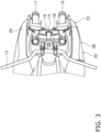
FIG. 3 is a plan view of a handle and the surroundings thereof. -
FIG. 4 is a perspective view of a storage box. -
FIG. 5 is a cross-sectional view of the storage box. -
FIG. 6 is a partial perspective view of the storage box. -
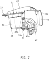
FIG. 7 is a partial perspective view of the storage box. -
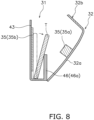
FIG. 8 is a diagram for explaining a state of a portable information terminal in transition from a closed state to an opened state. -
FIG. 9 is a diagram for explaining a modification of an inner sidewall. - A storage box for a straddled vehicle according to a preferred embodiment will be hereinafter explained with reference to drawings.
FIG. 1 is a side view of a straddledvehicle 1 including astorage box 30 according to the preferred embodiment.FIG. 2 is a front view of the straddledvehicle 1. It should be noted that in the following explanation, terms indicating such directions as "back and forth", "up and down", and "right and left" are explained based on directions seen from a rider in operation of the straddledvehicle 1. Therefore, a right-and-left direction is synonymous with a vehicle width direction. Besides, the term "outer side in a vehicle width direction" means a side far from the center of the straddledvehicle 1 in the vehicle width direction. By contrast, the term "inner side in the vehicle width direction" means a side near to the center of the straddledvehicle 1 in the vehicle width direction. - In the present specification, a condition of a constituent element extending in a vehicle back-and-forth direction (extending forward and/or rearward) is not limited to a condition of the constituent element extending in a direction orthogonal to a vehicle up-and-down direction and the vehicle width direction. The condition of the constituent element extending in the vehicle back-and-forth direction encompasses a condition of the constituent element extending to tilt relative to the vehicle up-and-down direction and/or the vehicle width direction. When described in detail, the vehicle back-and-forth direction encompasses a direction closer to the vehicle back-and-forth direction. The direction closer to the vehicle back-and-forth direction refers to, for instance, a direction that forms angles, the smaller of which is 45 degrees or less, together with the vehicle back-and-forth direction. The settings herein described are also true of the vehicle width direction (rightward and/or leftward directions) and the vehicle up-and-down direction (upward and/or downward directions).
- The straddled
vehicle 1 includes avehicle body frame 2, asteering device 3, a tank-like member 4, aseat 5, a power unit 6, afront wheel 7, and arear wheel 8. - The
vehicle body frame 2 includes a head pipe 11, amain frame 12, and arear frame 13. Themain frame 12 is connected to the head pipe 11. Themain frame 12 extends rearward from the head pipe 11. Therear frame 13 is connected to themain frame 12. Therear frame 13 extends rearward from themain frame 12. - The
steering device 3 is supported by the head pipe 11 so as to be turnable. Thesteering device 3 supports thefront wheel 7 such that thefront wheel 7 is made rotatable. Thesteering device 3 includes a steeringshaft 14, ahandle 15, a rightfront fork 16, a leftfront fork 17, anupper bracket 18, and alower bracket 19. - The steering
shaft 14 is inserted into the head pipe 11. Thehandle 15 is disposed further on the upper side than the head pipe 11. Thehandle 15 is connected to the steeringshaft 14. Thehandle 15 extends in the right-and-left direction. The right and leftfront forks shaft 14 through the upper andlower brackets front forks front wheel 7 such that thefront wheel 7 is made rotatable. - The tank-
like member 4 is disposed behind the head pipe 11. The tank-like member 4 is supported by themain frame 12. In the present preferred embodiment, the tank-like member 4 is a fuel tank.FIG. 2 shows the tank-like member 4 in a schematic manner. - The
seat 5 is disposed behind the tank-like member 4. Theseat 5 is disposed above therear frame 13. - The power unit 6 is disposed below the tank-
like member 4. The power unit 6 is supported by themain frame 12. The power unit 6 includes, for instance, an internal combustion engine. The power unit 6 generates a drive force. In the present preferred embodiment, the drive force generated by the power unit 6 is transferred to therear wheel 8. - The
rear wheel 8 is supported by themain frame 12 through a swing arm 9 supported by themain frame 12. Therear wheel 8 is supported by the swing arm 9 so as to be rotatable. Therear wheel 8 is driven by the drive force generated by the power unit 6. - The straddled
vehicle 1 includes awind shield 20, a front cowl 21, aright side cowl 22, aleft side cowl 23, a right side cover 25 (exemplary exterior cover), and aleft side cover 26. Thewind shield 20 is disposed above the front cowl 21. - The front cowl 21 is disposed in front of the head pipe 11. The
right side cowl 22 is disposed on the right of the head pipe 11. As shown inFIG. 1 , theright side cowl 22 extends forward from theright side cover 25 in a vehicle side view. Theright side cowl 22 extends downward from theright side cover 25 in the vehicle side view. Theleft side cowl 23 is disposed on the left of the head pipe 11. Theleft side cowl 23 extends forward from theleft side cover 26 in the vehicle side view. Theleft side cowl 23 extends downward from theleft side cover 26 in the vehicle side view. - The
right side cover 25 is connected to theright side cowl 22. Theright side cover 25 is disposed above theright side cowl 22. Theright side cover 25 is disposed not only lateral to thesteering device 3 but also on one side of the head pipe 11 in the vehicle width direction. Theright side cover 25 is disposed on the right of the head pipe 11. Theright side cover 25 overlaps with the head pipe 11 in the vehicle side view. Theright side cover 25 is remote from thesteering device 3 in the vehicle width direction. Theright side cover 25 is disposed on the right of thesteering device 3. Theright side cover 25 overlaps with the steeringshaft 14 of thesteering device 3 in the vehicle side view. Theright side cover 25 is fixed to thevehicle body frame 2 through a bracket (not shown in the drawings). Theright side cover 25 may be fixed to the tank-like member 4. - The
right side cover 25 extends in the vehicle back-and-forth direction. Theright side cover 25 extends further rearward than theright side cowl 22. Theright side cover 25 is disposed between theright side cowl 22 and the tank-like member 4 in the vehicle back-and-forth direction. Theright side cover 25 is disposed lateral to the tank-like member 4. In the present preferred embodiment, a rear portion of theright side cover 25 is disposed laterally on the right of the tank-like member 4 and overlaps with the tank-like member 4 in the vehicle side view. - The
left side cover 26 is connected to theleft side cowl 23. Theleft side cover 26 is disposed above theleft side cowl 23. Theleft side cover 26 is disposed not only lateral to thesteering device 3 but also on the other side of the head pipe 11 in the vehicle width direction. Theleft side cover 26 is disposed on the left of the head pipe 11. Theleft side cover 26 overlaps with the head pipe 11 in the vehicle side view. Theleft side cover 26 is remote from thesteering device 3 in the vehicle width direction. Theleft side cover 26 is disposed on the left of thesteering device 3. Theleft side cover 26 overlaps with the steeringshaft 14 of thesteering device 3 in the vehicle side view. - The
left side cover 26 extends in the vehicle back-and-forth direction. Theleft side cover 26 extends further rearward than theleft side cowl 23. Theleft side cover 26 is disposed between theleft side cowl 23 and the tank-like member 4 in the vehicle back-and-forth direction. Theleft side cover 26 is disposed lateral to the tank-like member 4. In the present preferred embodiment, a rear portion of theleft side cover 26 is disposed laterally on the left of the tank-like member 4 and overlaps with the tank-like member 4 in the vehicle side view. -
FIG. 4 is a perspective view of thestorage box 30.FIG. 5 is a cross-sectional view of thestorage box 30.FIGS. 6 and7 are partial perspective views of thestorage box 30. Thestorage box 30 stores a portable information terminal T. The portable information terminal T is, for instance, a smartphone. - The
storage box 30 is disposed further on the front side than theseat 5. Thestorage box 30 is disposed below a turning trajectory of thehandle 15. Thestorage box 30 is disposed further on the right side than the head pipe 11. Thestorage box 30 is disposed laterally on the right of the head pipe 11. Thestorage box 30 overlaps with the head pipe 11 in the vehicle side view. - The
storage box 30 is disposed on the right of thesteering device 3. Thestorage box 30 overlaps with the steeringshaft 14 of thesteering device 3 in the vehicle side view. Thestorage box 30 is disposed further on the upper side than thelower bracket 19. Thestorage box 30 is disposed inside theright side cover 25. Thestorage box 30 is disposed further on the front side than the tank-like member 4. Thestorage box 30 does not overlap with the tank-like member 4 in the vehicle side view. Thestorage box 30 overlaps with the tank-like member 4 in the vehicle front view. - The
storage box 30 includes astorage portion 31, alid portion 32, anupper surface portion 33, an opposedportion 34, at least oneelastic member 35, ashaft portion 36, ashaft support portion 37, and alid cover 38. It should be noted that inFIG. 4 , thelid cover 38 is omitted in illustration. - The
storage portion 31 is disposed on the right of thesteering device 3. Thestorage portion 31 is fixed to a member configured not to be turned together with thesteering device 3. Thestorage portion 31 is fixed to theright side cover 25. The dimension of thestorage portion 31 is greater in the vehicle back-and-forth direction than not only in the vehicle up-and-down direction but also in the vehicle width direction. The dimension of thestorage portion 31 is greater in the vehicle up-and-down direction than in the vehicle width direction. - The
storage portion 31 includes anopening 41, abottom surface portion 42, aninner sidewall 43, afront surface portion 44, arear surface portion 45, at least onerestriction portion 46, anattachment portion 47, and a drain hole 48 (seeFIG. 7 ). - The
opening 41 serves as an opening for putting-in and taking-out of the portable information terminal T and is opened not only upward but also outward in the vehicle width direction. Theopening 41 is defined by theinner sidewall 43, thefront surface portion 44, and therear surface portion 45. - When the
lid portion 32 is opened, thestorage portion 31 is uncovered upward. When thelid portion 32 is opened, thestorage portion 31 is uncovered outward in the vehicle width direction except for at the restriction portion (or portions) 46. It should be noted that in the following explanation, the state that thelid portion 32 is opened will be referred to as "an opened state", whereas the state that thelid portion 32 is closed will be referred to as "a closed state". In other words, the opened state means that theopening 41 is opened (uncovered), whereas the closed state means that theopening 41 is closed (covered).FIG. 4 shows the opened state, whereasFIG. 5 shows the closed state. - The
bottom surface portion 42 serves as a portion on which the portable information terminal T is put. The portable information terminal T is put on thebottom surface portion 42 such that the lengthwise direction thereof is matched with the vehicle back-and-forth direction. The portable information terminal T is put on thebottom surface portion 42 such that one of the width directional lateral surfaces thereof is put thereon. Thebottom surface portion 42 is disposed lateral to the head pipe 11. Thebottom surface portion 42 extends in a direction intersecting with the vehicle up-and-down direction. Thebottom surface portion 42 extends in approximately a horizontal direction. The dimension of thebottom surface portion 42 is greater in the vehicle back-and-forth direction than in the vehicle width direction. Thebottom surface portion 42 tilts down forward. Thebottom surface portion 42 extends to gradually approach to the head pipe 11 from the rear to the front. The front end of thebottom surface portion 42 is located further on the inner side than the rear end thereof in the vehicle width direction. The front end of thebottom surface portion 42 is located further on the rear side than that of theright side cover 25. The rear end of thebottom surface portion 42 is located further on the rear side than the head pipe 11. The rear end of thebottom surface portion 42 is located further on the front side than that of theright side cover 25. - The
inner sidewall 43 extends in a direction intersecting with the vehicle width direction. Theinner sidewall 43 extends in approximately both the vehicle up-and-down direction and the vehicle back-and-forth direction. Theinner sidewall 43 is disposed between thefront surface portion 44 and therear surface portion 45 in the vehicle back-and-forth direction. Theinner sidewall 43 is connected to thebottom surface portion 42, thefront surface portion 44, and therear surface portion 45. Theinner sidewall 43 extends upward from a vehicle width directionally inner portion of thebottom surface portion 42. Theinner sidewall 43 extends to gradually approach to the head pipe 11 from rear to front. The front end of theinner sidewall 43 is located further on the inner side than the rear end thereof in the vehicle width direction. In the closed state, theinner sidewall 43 is opposed to thelid portion 32 in the vehicle width direction. - The
front surface portion 44 extends in a direction intersecting with the vehicle back-and-forth direction. Thefront surface portion 44 extends upward from the front end of thebottom surface portion 42. Thefront surface portion 44 extends outward from the front end of theinner sidewall 43 in the vehicle width direction. - The
rear surface portion 45 extends in a direction intersecting with the vehicle back-and-forth direction. Therear surface portion 45 is opposed to thefront surface portion 44 in the vehicle back-and-forth direction. Therear surface portion 45 extends upward from the rear end of thebottom surface portion 42. Therear surface portion 45 extends outward from the rear end of theinner sidewall 43 in the vehicle width direction. Therear surface portion 45 is located further on the rear side than the head pipe 11. Therear surface portion 45 is located further on the front side than the rear end of theright side cover 25. Therear surface portion 45 is disposed further on the rear side than the restriction portion (or portions) 46. Therear surface portion 45 defines part of theopening 41. Therear surface portion 45 includes anedge 45a extending not only downward but also outward in the vehicle width direction. Theedge 45a is disposed on the upper end of a vehicle width directionally outer portion of therear surface portion 45. Theedge 45a defines part of theopening 41. - The restriction portion (or portions) 46 restricts the portable information terminal T, put on the
bottom surface portion 42, from moving outward in the vehicle width direction. In the opened state, a space is produced between theinner sidewall 43 and the restriction portion (or portions) 46 so as to allow the portable information terminal T to tilt toward the restriction portion (or portions) 46. - The
storage portion 31 stores the portable information terminal T such that the portable information terminal T stands between theinner sidewall 43 and the restriction portion (or portions) 46. The standing state of the portable information terminal T means that a lateral surface of the portable information terminal T is put on thebottom surface portion 42. In the present preferred embodiment, thestorage portion 31 stores the portable information terminal T such that a width directional lateral surface of the portable information terminal T is put on thebottom surface portion 42. Thestorage portion 31 may be configured to store the portable information terminal T such that a lengthwise directional lateral surface of the portable information terminal T is put on thebottom surface portion 42. - As shown in
FIG. 5 , the restriction portion (or portions) 46 is remote from the portable information terminal T in the closed state. When thelid portion 32 transitions from the closed state shown inFIG. 5 to the opened state shown inFIG. 4 , the restriction portion (or portions) 46 contacts with the portable information terminal T on the front or rear surface side of the portable information terminal T so as to restrict movement of the portable information terminal T. When described in detail, as schematically shown inFIG. 8 , in transition of thelid portion 32 from the closed state to the opened state, the portable information terminal T tilts toward the restriction portion (or portions) 46 due to a recoil caused in releasing the pressing force applied by the elastic member (or members) 35 and is thereby moved to the restriction portion (or portions) 46. Accordingly, the portable information terminal T contacts on the front or rear surface side thereof with the restriction portion (or portions) 46, whereby movement thereof is restricted. In other words, at least an upper portion of the portable information terminal T is remote from theinner sidewall 43 in the closed state; hence, the portable information terminal T is retained by the restriction portion (or portions) 46, while tilting with respect to theinner sidewall 43. - The first restriction portion (or portions) 46a is disposed further on the outer side than the
inner sidewall 43 in the vehicle width direction. The restriction portion (or portions) 46 is opposed to theinner sidewall 43 in the vehicle width direction. The dimension of the restriction portion (or portions) 46 is preferably greater than or equal to a quarter of, and less than or equal to three quarters of, that of theinner sidewall 43 in the vehicle up-and-down direction. The dimension of the restriction portion (or portions) 46 is preferably less than that of thestorage portion 31 in the vehicle back-and-forth direction. - The restriction portion or
portions 46 include afirst restriction portion 46a and asecond restriction portion 46b. Thefirst restriction portion 46a extends upward from thebottom surface portion 42. Thefirst restriction portion 46a is disposed further on the lower side than the upper end of theinner sidewall 43. The dimension of thefirst restriction portion 46a is greater than or equal to a quarter of, and less than or equal to three quarters of, that of theinner sidewall 43 in the vehicle up-and-down direction. The dimension of thefirst restriction portion 46a is less than that of thestorage portion 31 in the vehicle back-and-forth direction. The dimension of thefirst restriction portion 46a is less than that of theinner sidewall 43 in the vehicle back-and-down direction. - The
second restriction portion 46b is disposed remote from thefirst restriction portion 46a in the vehicle back-and-forth direction. Thesecond restriction portion 46b is disposed further on the front side than thefirst restriction portion 46a. Thesecond restriction portion 46b extends upward from thebottom surface portion 42 and is connected to thefront surface portion 44. The upper edge of thesecond restriction portion 46b extends not only rearward but also downward. The dimension of thesecond restriction portion 46b is greater than or equal to a quarter of, and less than or equal to three quarters of, that of theinner sidewall 43 in the vehicle up-and-down direction. The dimension of thesecond restriction portion 46b is less than that of theinner sidewall 43 in the vehicle back-and-forth direction. - The
attachment portion 47 serves as a portion for attaching a power supply device (not shown in the drawings). The power supply device is, for instance, a power socket provided as an accessory socket. The power supply device may connect therethrough the portable information terminal T and an electronic device installed in the straddledvehicle 1 such that intercommunication of data is enabled between the portable information terminal T and the electronic device. Theattachment portion 47 is formed by bulging a rear portion of theinner sidewall 43 inward in the vehicle width direction. Theattachment portion 47 includes anattachment hole 47a to which the power supply device is attached. Theattachment hole 47a is disposed further on the inner side than thebottom surface portion 42 in the vehicle width direction. Theattachment hole 47a is disposed below theupper surface portion 33. - As shown in
FIG. 7 , thedrain hole 48 is disposed in thebottom surface portion 42. Thedrain hole 48 is provided in the vehicle width directionally inner one of the front corners of thebottom surface portion 42. - Cushioning
members 50 are disposed on the upper surface of thebottom surface portion 42, the rear surface of thefront surface portion 44, the front surface of therear surface portion 45, and the internal surface of thelid portion 32, respectively. - The
lid portion 32 closes (covers) and opens (uncovers) theopening 41. Thelid portion 32 is capable of transitioning to the closed state and the opened state. In the closed state, thelid portion 32 covers thebottom surface portion 42, theinner sidewall 43, thefront surface portion 44, therear surface portion 45, and theupper surface portion 33. Thelid portion 32 is supported by theshaft portion 36 so as to be pivotable. Thelid portion 32 is pivotable between an opened position shown inFIG. 4 and a closed position shown inFIG. 5 . Thelid portion 32 is set to be pivotable in an angular range of approximately 20° to 30°. It should be noted that thelid portion 32 is preferably pivotable in an angular range of 45° or less. Thelid portion 32 is pivotable with respect to theright side cover 25. - The
lid portion 32 is configured to be opened outward in the vehicle width direction with respect to thestorage portion 31. Thelid portion 32 is configured to be opened outward in the vehicle width direction with respect to theinner sidewall 43. When moved from the closed position to the opened position, thelid portion 32 is opened outward in the vehicle width direction. Thelid portion 32 is configured to be opened in a direction that the portable information terminal T tilts in transition from the closed state to the opened state. In other words, thelid portion 32 tilts in an identical direction to the portable information terminal T with respect to theinner sidewall 43 in transition from the closed state to the opened state. As shown inFIGS. 4 and5 , when thelid portion 32 is in the opened position, an upper portion thereof is located further on the outer side in the vehicle width direction than when thelid portion 32 is in the closed position. Thelid portion 32 is biased to the opened position by a hinge spring (not shown in the drawings) disposed below thestorage portion 31. - As shown in
FIG. 5 , thelid portion 32 includes awall portion 32a, acanopy portion 32b, and an engagedportion 32c. In the closed state, thewall portion 32a extends in a direction intersecting with the vehicle width direction. In the closed state, thewall portion 32a is opposed to theinner sidewall 43 in the vehicle width direction. Thecanopy portion 32b extends inward from the upper end of thewall portion 32a in the vehicle width direction. In the closed state, thecanopy portion 32b covers theupper surface portion 33. In the closed state, adistal end portion 321b, which is a vehicle width directionally inner end portion of thecanopy portion 32b, is located further on the inner side than theinner sidewall 43 in the vehicle width direction. The engagedportion 32c is provided on the lower surface of thedistal end portion 321b of thecanopy portion 32b. The engagedportion 32c extends downward from the lower surface of thedistal end portion 321b of thecanopy portion 32b. The engagedportion 32c is shaped to recess from the inner side to the outer side in the vehicle width direction. - The
upper surface portion 33 extends in a direction intersecting with the vehicle up-and-down direction. Theupper surface portion 33 extends from thestorage portion 31 in a direction of closing thelid portion 32. Theupper surface portion 33 extends inward from thestorage portion 31 in the vehicle width direction. In the vicinity of the upper end of theinner sidewall 43 of thestorage portion 31, theupper surface portion 33 extends inward from theinner sidewall 43 in the vehicle width direction. Theupper surface portion 33 is disposed further on the lower side than the aforementioned upper end (43a) of theinner sidewall 43. Theupper end 43a of theinner sidewall 43 protrudes further upward than theupper surface portion 33. Because of this, a step is provided between theupper surface portion 33 and theinner sidewall 43. In the closed state, theupper surface portion 33 is disposed below thecanopy portion 32b so as to be covered therewith. - The
upper surface portion 33 includes a throughhole 33a and a plurality ofdrain holes 33b. The throughhole 33a and the plural drain holes 33b are disposed between theopposed portion 34 and thestorage portion 31. The throughhole 33a and the plural drain holes 33b are disposed between theopposed portion 34 and theinner sidewall 43. The throughhole 33a and the plural drain holes 33b penetrate theupper surface portion 33 in the vehicle up-and-down direction. The throughhole 33a is provided in the vicinity of the middle of theupper surface portion 33 in the vehicle back-and-forth direction. The plural drain holes 33b are provided on the front side and the rear side of the throughhole 33a. - The opposed
portion 34 is connected to theupper surface portion 33. The opposedportion 34 extends upward from theupper surface portion 33. The opposedportion 34 is disposed further on the inner side than the plural drain holes 33b in the vehicle width direction. In the closed state, the opposedportion 34 is opposed to thedistal end portion 321b of thecanopy portion 32b. In the closed state, aseal member 40 is disposed between theopposed portion 34 and thedistal end portion 321b of thecanopy portion 32b so as to seal a gap produced therebetween. Theseal member 40 is fixed to the opposedportion 34. Theseal member 40 may be fixed to thedistal end portion 321b of thecanopy portion 32b. As shown inFIG. 7 , a plurality ofribs 51 are provided on the inner side of the opposedportion 34 in the vehicle width direction so as to be connected to theupper surface portion 33 and the opposedportion 34. - The elastic member (or members) 35 is disposed on at least either the
lid portion 32 or theinner sidewall 43. In the closed state, the portable information terminal T is pressed by the elastic member (or members) 35 in the thickness direction thereof, while interposed between the elastic member (or members) 35 and either thelid portion 32 or theinner sidewall 43; accordingly, the portable information terminal T is retained in thestorage portion 31. In the present preferred embodiment, in the closed state, the elastic member (or members) 35 presses the portable information terminal T in the vehicle width direction. For example, the elastic member (or members) 35 is made of such a material as urethane, rubber, or so forth. - The one or more
elastic members 35 include a firstelastic member 35a and a secondelastic member 35b. The firstelastic member 35a is disposed on thelid portion 32. The firstelastic member 35a is fixed to the internal surface of thewall portion 32a of thelid portion 32. In the closed state, the firstelastic member 35a is disposed above thefirst restriction portion 46a. The firstelastic member 35a, at least in part, is disposed at an identical height to the center of theinner sidewall 43 in the vehicle up-and-down direction. In the closed state, the firstelastic member 35a overlaps with the height center of theinner sidewall 43 in the vehicle side view. When the portable information terminal T is stored in thestorage portion 31 in the closed state, the firstelastic member 35a extends in the lengthwise direction of the portable information terminal T. In the present preferred embodiment, the firstelastic member 35a extends in the vehicle back-and-forth direction. - As shown in
FIG. 5 , thefirst restriction portion 46a herein extends from thebottom surface portion 42 to the vicinity of the firstelastic member 35a. In the closed state, thefirst restriction portion 46a is disposed below the firstelastic member 35a. The height of thefirst restriction portion 46a is greater than or equal to a half of the dimension from thebottom surface portion 42 to the firstelastic member 35a in the closed state. Thesecond restriction portion 46b, in part, is disposed further on the upper side than the firstelastic member 35a. - The second
elastic member 35b is disposed on theinner sidewall 43. The secondelastic member 35b is fixed to the surface of theinner sidewall 43 on the outer side of theinner sidewall 43 in the vehicle width direction. In the closed state, the secondelastic member 35b is opposed to the firstelastic member 35a in the vehicle width direction. The secondelastic member 35b is disposed at least in part at an identical height to the center of theinner sidewall 43 in the vehicle up-and-down direction. In the closed state, the secondelastic member 35b overlaps with the height center of theinner sidewall 43 in the vehicle side view. When the portable information terminal T is stored in thestorage portion 31, the secondelastic member 35b extends in the lengthwise direction of the portable information terminal T. In the present preferred embodiment, the secondelastic member 35b extends in the vehicle back-and-forth direction. - The
shaft portion 36 supports thelid portion 32 such that thelid portion 32 is made pivotable. Theshaft portion 36 extends in the vehicle back-and-forth direction. In the present preferred embodiment, theshaft portion 36 extends to tilt with respect to not only the vehicle up-and-down direction but also the vehicle width direction. Theshaft portion 36 extends from the vehicle rear side to the vehicle front side so as to tilt down to the inner side in the vehicle width direction. It should be noted that theshaft portion 36 may extend in parallel to the vehicle back-and-forth direction, or alternatively, may extend to tilt with respect to either the vehicle up-and-down direction or the vehicle width direction. - The
shaft portion 36 is disposed below thestorage portion 31. Theshaft portion 36 overlaps with thestorage portion 31 in a vehicle plan view. Theshaft portion 36 is supported by theshaft support portion 37. Theshaft portion 36 is disposed further on the outer side than theinner sidewall 43 in the vehicle width direction. - The
shaft support portion 37 is disposed below thestorage portion 31. Theshaft support portion 37 is provided on a lower portion of thebottom surface portion 42. - The
lid cover 38 is fixed to thelid portion 32 outside thelid portion 32 so as to be unitarily pivotable therewith. For example, at least one resin rivet is inserted into thelid cover 38 from the inside of thelid portion 32, whereby thelid cover 38 is fixed to thelid portion 32. Thelid cover 38 is disposed to compose part of theright side cover 25 in the vehicle side view. For example, thelid cover 38 is disposed to be flush with theright side cover 25 at a portion thereof adjoining theright side cover 25. - As shown in
FIG. 5 , the straddledvehicle 1 includes an opening andclosing mechanism 60 and an operatingmember 62. When thelid portion 32 is moved to the closed position, the opening andclosing mechanism 60 keeps thelid portion 32 in the closed state. The opening andclosing mechanism 60 releases the closed state in response to operating the operatingmember 62. - As shown in
FIGS. 4 and5 , the opening andclosing mechanism 60 includes an engagingprotrusion 60a. The engagingprotrusion 60a is disposed to be protrusible and retractable with respect to the throughhole 33a. The engagingprotrusion 60a is biased upward by an urging member (not shown in the drawings). In the closed state, the engagingprotrusion 60a protrudes upward from the throughhole 33a so as to engage with the engagedportion 32c of thelid portion 32. Accordingly, thelid portion 32 is kept in the closed state, while being restricted from moving to the opened position. On the other hand, when the operatingmember 62 is operated, the engagingprotrusion 60a is pulled into the throughhole 33a. When the operatingmember 62 is operated in the closed state, the engagedportion 32c of thelid portion 32 is released from being engaged with the engagingprotrusion 60a. Accordingly, thelid portion 32 is moved from the closed position to the opened position. - The engaging
protrusion 60a includes a slope 601a. The slope 601a is provided on the upper surface of the engagingprotrusion 60a. The slope 601a tilts down to the outer side in the vehicle width direction. When thelid portion 32 is moved from the opened position to the closed position, thedistal end portion 321b of thecanopy portion 32b of thelid portion 32 contacts with the slope 601a from the outer side in the vehicle width direction. Accordingly, the engagingprotrusion 60a is pressed downward to be pulled into the throughhole 33a. When the engagedportion 32c of thelid portion 32 gets over the engagingprotrusion 60a to the inner side in the vehicle width direction, the engagingprotrusion 60a engages with the engagedportion 32c of thelid portion 32, whereby thelid portion 32 is restricted from moving to the opened position. - The operating
member 62 serves as a member to be operated for causing thelid portion 32 to perform an opening action. The operatingmember 62 is a member to be operated for pulling the engagingprotrusion 60a into the throughhole 33a. The operatingmember 62 is coupled to the opening andclosing mechanism 60. The operatingmember 62 is a member operable by pressing. The operatingmember 62 is, for instance, a push button pressable from the inner side to the outer side in the vehicle width direction. The operatingmember 62 is disposed on the external surface of a vehicle width directionally inner portion of thestorage portion 31. - In the
storage box 30 for the straddledvehicle 1 according to the present aspect, when thelid portion 32 of thestorage box 30 is closed, the portable information terminal T stored in thestorage portion 31 of thestorage box 30 is retained therein, while being pressed by the elastic member (or members) 35 in the thickness direction thereof. Accordingly, the portable information terminal T can be retained by an easy operation, i.e., only by pivoting thelid portion 32 of thestorage box 30. Therefore, when a rider is riding on the vehicle, for instance, the portable information terminal T stored in thestorage box 30 can be easily retained, while the vehicle can be kept in balance. - The portable information terminal T is stored to stand between the
inner sidewall 43 and the restriction portion (or portions) 46; besides, a space is produced between theinner sidewall 43 and the restriction portion (or portions) so as to allow the portable information terminal T to tilt toward the restriction portion (or portions) 46 when thelid portion 32 is opened. Because of this, when the rider is riding on the vehicle, for instance, it is made easy for the rider to put/take the portable information terminal T in/out of thestorage portion 31. - The
inner sidewall 43 extends in approximately the vehicle up-and-down direction; hence, in transition of thelid portion 32 from the closed state to the opened state, it is made possible to move the portable information terminal T to the restriction portion (or portions) 46 due to the recoil caused in releasing the pressing force applied by the elastic member (or members) 35 to press the portable information terminal T. Because of this, when the rider riding on the vehicle opens thelid portion 32, for instance, it is made easy for the rider to take the portable information terminal T out of thestorage portion 31. - The first
elastic member 35a is disposed on thelid portion 32; hence, when thelid portion 32 transitions from the opened state to the closed state, the portable information terminal T can be supported by the firstelastic member 35a until contacting with the restriction portion (or portions) 46. Besides, theshaft portion 36 is disposed below thestorage portion 31; hence, even when the portable information terminal T slips out of thestorage portion 31 in the opened state, the portable information terminal T can be inhibited from dropping from thestorage box 30 by thelid portion 32. - The
storage box 30 is fixed to a member configured not to be turned together with thesteering device 3; hence, when the rider is riding on the vehicle, the portable information terminal T stored in thestorage box 30 can be easily retained, while the vehicle can be kept in balance. Besides, the portable information terminal T is unlikely to be affected by turning of thesteering device 3. - The
opening 41 is opened not only upward but also outward in the vehicle width direction; besides, the restriction portion (or portions) 46 is not provided on thestorage portion 31 entirely in the vehicle width direction. Because of this, the portable information terminal T can be easily put/taken in/out of thestorage portion 31. - One preferred embodiment of the present invention has been explained above. However, the present invention is not limited to the preferred embodiment described above, and a variety of changes can be made without departing from the gist of the present invention.
- The
storage box 30 may be changed in layout. Thestorage box 30 may be disposed inside theleft side cover 26. Thestorage portion 31 may be changed in configuration. The opening andclosing mechanism 60 and the operatingmember 62 may be changed in configuration. - The straddled
vehicle 1 may be an electric straddled vehicle. In this case, the power unit 6 may include an electric motor, while the tank-like member 4 may include a battery. The battery may be stored in the tank-like member 4. - The straddled
vehicle 1 may be a vehicle of a scooter type. In this case, theshaft portion 36 may extend in the vehicle width direction; besides, thestorage box 30, at least in part, may be disposed in, for instance, a leg shield disposed in front of theseat 5. - The
lid cover 38 may be omitted. In this case, thelid portion 32 of thestorage box 30 may be disposed to compose part of theright side cover 25 in the vehicle side view. - Either the first
elastic member 35a or the secondelastic member 35b may be omitted. For example, when the firstelastic member 35a is omitted, thelid portion 32 may be configured to contact at the internal surface of thewall portion 32a with the portable information terminal T. - As shown in
FIG. 9 , theinner sidewall 43 may extend to gradually approach the restriction portion (or portions) 46 from below to above. In other words, in transition from the closed state to the opened state, thestorage box 30 may be configured to move the portable information terminal T to the restriction portion (or portions) 46 by the tilt of theinner sidewall 43. The tilt of theinner sidewall 43 may be realized by changing the thickness of the secondelastic member 35b. In this case, in transition from the closed state to the opened state, the portable information terminal T can be easily moved to the restriction portion (or portions) 46. Alternatively, the upper surface of thebottom surface portion 42 may tilt down toward the restriction portion (or portions) 46. -
- 1
- Straddled vehicle
- 3
- Steering device
- 5
- Seat
- 25
- Right side cover (exemplary side cover)
- 30
- Storage box
- 31
- Storage portion
- 32
- Lid portion
- 34
- Opposed portion
- 35
- Elastic member
- 36
- Shaft portion
- 38
- Lid cover
- 41
- Opening
- 42
- Bottom surface portion
- 43
- Inner sidewall
- 45
- Rear surface portion
- 45a
- Edge
- 46
- Restriction portion
- T
- Portable Information Terminal
Claims (18)
- A storage box (30) for a straddled vehicle (1), the storage box (30) being configured to store a portable information terminal (T), the storage box (30) comprising:a storage portion (31) including an opening (41) for putting-in and taking-out of the portable information terminal (T), an inner sidewall (43), and at least one restriction portion (46) opposed to the inner sidewall (43), the storage portion (31) being configured to store the portable information terminal (T) such that the portable information terminal (T) stands between the inner sidewall (43) and the at least one restriction portion (46);a lid portion (32) capable of transitioning to a closed state and an opened state, the lid portion (32) being configured to close the opening in the closed state, the lid portion (32) being configured to open the opening in the opened state, the lid portion (32) being opposed to the inner sidewall (43) in the closed state;at least one elastic member (35) disposed on at least either the lid portion (32) or the inner sidewall (43), the at least one elastic member (35) being configured to press the portable information terminal (T) in a thickness direction of the portable information terminal (T) between the lid portion (32) or the inner sidewall (43) in the closed state to hold the portable information terminal (T) in the storage portion (31); anda shaft portion (36) configured to pivotably support the lid portion (32), whereinthe inner sidewall (43) extends in approximately a vehicle up-and-down direction or extends to gradually approach the at least one restriction portion (46) from below to above,the inner sidewall (43) and the at least one restriction portion (46) produce a space therebetween so as to allow the portable information terminal (T) to tilt toward the at least one restriction portion (46) in the opened state, andthe at least one restriction portion (46) is apart from the portable information terminal (T) in the closed state, the at least one restriction portion (46) contacting with the portable information terminal (T) on a front or rear surface side of the portable information terminal (T) so as to restrict movement of the portable information terminal (T) when the lid portion (32) transitions from the closed state to the opened state.
- The storage box for the straddled vehicle (1) according to claim 1, wherein the at least one elastic member (35) is disposed at least in part at an identical height to a center of the inner sidewall (43) in the vehicle up-and-down direction in the closed state.
- The storage box for the straddled vehicle (1) according to claim 2, wherein the at least one elastic member (35) extends in a lengthwise direction of the portable information terminal (T), when the portable information terminal (T) is stored in the storage portion (31) in the closed state.
- The storage box for the straddled vehicle (1) according to claim 1, wherein the at least one elastic member (35) is disposed on the lid portion (32).
- The storage box for the straddled vehicle (1) according to claim 4, wherein the at least one restriction portion (36) is disposed below the at least one elastic member (35) in the closed state.
- The storage box for the straddled vehicle (1) according to claim 5, whereinthe storage portion (31) further includes a bottom surface portion (42) extending in a direction intersecting with the vehicle up-and-down direction,the at least one restriction portion (46) extends upward from the bottom surface portion (42), andthe at least one restriction portion (46) has a height larger than or equal to a half of a dimension from the bottom surface portion (42) to the at least one elastic member (35) in the closed state.
- The storage box for the straddled vehicle (1) according to claim 6, wherein the at least one restriction portion (46) extends from the bottom surface portion (42) to a vicinity of the at least one elastic member (35).
- The storage box for the straddled vehicle (1) according to claim 6, wherein the at least one restriction portion (46) has a dimension larger than or equal to a quarter of and less than or equal to three quarters of a dimension of the inner sidewall (43) in the vehicle up-and-down direction.
- The storage box for the straddled vehicle (1) according to claim 1, wherein the at least one elastic member (35) includes a first elastic member (35a) and a second elastic member (35b), the first elastic member (35a) being disposed on the lid portion (32), the second elastic member (35b) being disposed on the inner sidewall (43) of the storage portion (31).
- The storage box for the straddled vehicle (1) according to any one of claims 1 to 9, wherein the storage portion (31) has a dimension in a vehicle back-and-forth direction larger than dimensions of the storage portion (31) in the vehicle up-and-down direction and in a vehicle width direction.
- The storage box for the straddled vehicle (1) according to claim 10, whereinthe at least one restriction portion (46) is opposed to the inner sidewall (43) in the vehicle width direction, andthe at least one restriction portion (46) has a dimension in the vehicle back-and-forth direction smaller than the dimension of the storage portion (31) in the vehicle back-and-forth direction.
- The storage box for the straddled vehicle (1) according to claim 10, whereinthe storage portion (31) further includes a bottom surface portion (42) extending in a direction intersecting with the vehicle up-and-down direction, andthe at least one restriction portion (46) includes a first restriction portion (46a) and a second restriction portion (46b), the first restriction portion (46a) extending upward from the bottom surface portion, the second restriction portion (46b) disposed apart from the first restriction portion (46a) in the vehicle back-and-forth direction.
- The storage box for the straddled vehicle (1) according to any one of claims 1 to 9, wherein the storage portion (31) is disposed forward of a seat (5) of the straddled vehicle (1), the storage portion (31) being fixed to a member configured not to be turned together with a steering device (3) of the straddled vehicle (1).
- The storage box for the straddled vehicle (1) according to any one of claims 1 to 9, wherein the storage portion (31) is disposed lateral to a steering device (3) of the straddled vehicle (1).
- The storage box for the straddled vehicle (1) according to any one of claims 1 to 9, wherein the shaft portion (36) is disposed below the storage portion (31).
- The storage box for the straddled vehicle (1) according to any one of claims 1 to 9, further comprising:a lid cover (38) fixed to the lid portion (32) outside the lid portion (32) so as to be unitarily pivotable therewith, whereinthe lid cover (32) is disposed to form part of an exterior cover of the straddled vehicle (1).
- The storage box for the straddled vehicle (1) according to any one of claims 1 to 9, wherein the opening (41) is opened upward and outward in a vehicle width direction.
- The storage box for the straddled vehicle (1) according to claim 17, whereinthe storage portion (31) is disposed forward of a seat (5) of the straddled vehicle (1),the storage portion (31) further includes a rear surface portion (45), the rear surface portion (45) being disposed rearward of the at least one restriction portion (46), the rear surface portion (45) defining part of the opening (41), andthe rear surface portion (45) includes an edge (45a) extending outward in the vehicle (1) width direction and downward.
Applications Claiming Priority (1)
| Application Number | Priority Date | Filing Date | Title |
|---|---|---|---|
| JP2022210591A JP7733635B2 (en) | 2022-12-27 | 2022-12-27 | Storage box for saddle-type vehicles |
Publications (2)
| Publication Number | Publication Date |
|---|---|
| EP4397581A1 true EP4397581A1 (en) | 2024-07-10 |
| EP4397581B1 EP4397581B1 (en) | 2025-07-09 |
Family
ID=89073254
Family Applications (1)
| Application Number | Title | Priority Date | Filing Date |
|---|---|---|---|
| EP23213604.4A Active EP4397581B1 (en) | 2022-12-27 | 2023-12-01 | Storage box for straddled vehicle |
Country Status (3)
| Country | Link |
|---|---|
| EP (1) | EP4397581B1 (en) |
| JP (1) | JP7733635B2 (en) |
| CN (1) | CN118254911A (en) |
Citations (4)
| Publication number | Priority date | Publication date | Assignee | Title |
|---|---|---|---|---|
| US20100012696A1 (en) * | 2008-07-18 | 2010-01-21 | Thomas Ferdinand Prager | Bicycle article carrier |
| JP2014043208A (en) * | 2012-08-28 | 2014-03-13 | Honda Motor Co Ltd | Storage structure of saddle riding type vehicle |
| JP2015083395A (en) | 2013-10-25 | 2015-04-30 | 本田技研工業株式会社 | Article storage structure of saddle riding type vehicle |
| EP3222506A2 (en) * | 2016-03-18 | 2017-09-27 | Yamaha Hatsudoki Kabushiki Kaisha | Vehicle |
Family Cites Families (1)
| Publication number | Priority date | Publication date | Assignee | Title |
|---|---|---|---|---|
| JP6014758B2 (en) * | 2013-05-31 | 2016-10-25 | 本田技研工業株式会社 | Motorcycle article storage structure |
-
2022
- 2022-12-27 JP JP2022210591A patent/JP7733635B2/en active Active
-
2023
- 2023-12-01 EP EP23213604.4A patent/EP4397581B1/en active Active
- 2023-12-26 CN CN202311808252.2A patent/CN118254911A/en active Pending
Patent Citations (4)
| Publication number | Priority date | Publication date | Assignee | Title |
|---|---|---|---|---|
| US20100012696A1 (en) * | 2008-07-18 | 2010-01-21 | Thomas Ferdinand Prager | Bicycle article carrier |
| JP2014043208A (en) * | 2012-08-28 | 2014-03-13 | Honda Motor Co Ltd | Storage structure of saddle riding type vehicle |
| JP2015083395A (en) | 2013-10-25 | 2015-04-30 | 本田技研工業株式会社 | Article storage structure of saddle riding type vehicle |
| EP3222506A2 (en) * | 2016-03-18 | 2017-09-27 | Yamaha Hatsudoki Kabushiki Kaisha | Vehicle |
Also Published As
| Publication number | Publication date |
|---|---|
| JP7733635B2 (en) | 2025-09-03 |
| CN118254911A (en) | 2024-06-28 |
| JP2024093931A (en) | 2024-07-09 |
| EP4397581B1 (en) | 2025-07-09 |
Similar Documents
| Publication | Publication Date | Title |
|---|---|---|
| EP4397581B1 (en) | Storage box for straddled vehicle | |
| EP3517418A1 (en) | Straddled vehicle with an storage pocket having a power supply | |
| EP4393799B1 (en) | Straddled vehicle | |
| EP4393800B1 (en) | Straddled vehicle | |
| JP2010116103A (en) | Motorcycle | |
| US20230373584A1 (en) | Straddle-type vehicle | |
| US8041408B2 (en) | Battery fastening apparatus and portable terminal using the same | |
| JP2005343367A (en) | Fuel lid mounting structure | |
| US11643175B2 (en) | Personal watercraft | |
| JP6002512B2 (en) | Mounting structure of portable information terminal for saddle-ride type vehicle | |
| US9315227B2 (en) | Housing structure in saddle type vehicle | |
| EP3912895B1 (en) | Straddled vehicle | |
| JPH07112686A (en) | Vehicle fuel lid | |
| JP3752826B2 (en) | Outboard motor fuel tank cap | |
| JP2004106794A (en) | Holding device of cellular phone | |
| EP4696594A1 (en) | Straddled vehicle | |
| JP4624865B2 (en) | Work vehicle | |
| JP2011121560A (en) | Side-view mirror and method of manufacturing side-view mirror | |
| EP4361009A1 (en) | Straddled vehicle | |
| US20040026949A1 (en) | Electric mobility scooter storage room | |
| JP3805285B2 (en) | Air conditioner remote control storage device | |
| JP5301332B2 (en) | Helmet storage structure | |
| CN212812240U (en) | Shell structure and bluetooth headset cabin of charging | |
| JP2012199102A (en) | Electronic apparatus | |
| JP2009045238A (en) | Game machine |
Legal Events
| Date | Code | Title | Description |
|---|---|---|---|
| PUAI | Public reference made under article 153(3) epc to a published international application that has entered the european phase |
Free format text: ORIGINAL CODE: 0009012 |
|
| STAA | Information on the status of an ep patent application or granted ep patent |
Free format text: STATUS: REQUEST FOR EXAMINATION WAS MADE |
|
| 17P | Request for examination filed |
Effective date: 20231201 |
|
| AK | Designated contracting states |
Kind code of ref document: A1 Designated state(s): AL AT BE BG CH CY CZ DE DK EE ES FI FR GB GR HR HU IE IS IT LI LT LU LV MC ME MK MT NL NO PL PT RO RS SE SI SK SM TR |
|
| P01 | Opt-out of the competence of the unified patent court (upc) registered |
Free format text: CASE NUMBER: APP_43530/2024 Effective date: 20240725 |
|
| GRAP | Despatch of communication of intention to grant a patent |
Free format text: ORIGINAL CODE: EPIDOSNIGR1 |
|
| STAA | Information on the status of an ep patent application or granted ep patent |
Free format text: STATUS: GRANT OF PATENT IS INTENDED |
|
| GRAJ | Information related to disapproval of communication of intention to grant by the applicant or resumption of examination proceedings by the epo deleted |
Free format text: ORIGINAL CODE: EPIDOSDIGR1 |
|
| STAA | Information on the status of an ep patent application or granted ep patent |
Free format text: STATUS: REQUEST FOR EXAMINATION WAS MADE |
|
| GRAP | Despatch of communication of intention to grant a patent |
Free format text: ORIGINAL CODE: EPIDOSNIGR1 |
|
| STAA | Information on the status of an ep patent application or granted ep patent |
Free format text: STATUS: GRANT OF PATENT IS INTENDED |
|
| INTG | Intention to grant announced |
Effective date: 20250218 |
|
| INTC | Intention to grant announced (deleted) | ||
| INTG | Intention to grant announced |
Effective date: 20250228 |
|
| RIN1 | Information on inventor provided before grant (corrected) |
Inventor name: NAOI, HAJIME Inventor name: SHINOHARA, SHOYA |
|
| GRAS | Grant fee paid |
Free format text: ORIGINAL CODE: EPIDOSNIGR3 |
|
| GRAA | (expected) grant |
Free format text: ORIGINAL CODE: 0009210 |
|
| STAA | Information on the status of an ep patent application or granted ep patent |
Free format text: STATUS: THE PATENT HAS BEEN GRANTED |
|
| AK | Designated contracting states |
Kind code of ref document: B1 Designated state(s): AL AT BE BG CH CY CZ DE DK EE ES FI FR GB GR HR HU IE IS IT LI LT LU LV MC ME MK MT NL NO PL PT RO RS SE SI SK SM TR |
|
| REG | Reference to a national code |
Ref country code: GB Ref legal event code: FG4D |
|
| REG | Reference to a national code |
Ref country code: CH Ref legal event code: EP |
|
| REG | Reference to a national code |
Ref country code: IE Ref legal event code: FG4D |
|
| REG | Reference to a national code |
Ref country code: DE Ref legal event code: R096 Ref document number: 602023004707 Country of ref document: DE |
|
| REG | Reference to a national code |
Ref country code: NL Ref legal event code: MP Effective date: 20250709 |
|
| PG25 | Lapsed in a contracting state [announced via postgrant information from national office to epo] |
Ref country code: PT Free format text: LAPSE BECAUSE OF FAILURE TO SUBMIT A TRANSLATION OF THE DESCRIPTION OR TO PAY THE FEE WITHIN THE PRESCRIBED TIME-LIMIT Effective date: 20251110 |
|
| PG25 | Lapsed in a contracting state [announced via postgrant information from national office to epo] |
Ref country code: NL Free format text: LAPSE BECAUSE OF FAILURE TO SUBMIT A TRANSLATION OF THE DESCRIPTION OR TO PAY THE FEE WITHIN THE PRESCRIBED TIME-LIMIT Effective date: 20250709 |
|
| REG | Reference to a national code |
Ref country code: AT Ref legal event code: MK05 Ref document number: 1811638 Country of ref document: AT Kind code of ref document: T Effective date: 20250709 |
|
| PG25 | Lapsed in a contracting state [announced via postgrant information from national office to epo] |
Ref country code: IS Free format text: LAPSE BECAUSE OF FAILURE TO SUBMIT A TRANSLATION OF THE DESCRIPTION OR TO PAY THE FEE WITHIN THE PRESCRIBED TIME-LIMIT Effective date: 20251109 |
|
| PG25 | Lapsed in a contracting state [announced via postgrant information from national office to epo] |
Ref country code: NO Free format text: LAPSE BECAUSE OF FAILURE TO SUBMIT A TRANSLATION OF THE DESCRIPTION OR TO PAY THE FEE WITHIN THE PRESCRIBED TIME-LIMIT Effective date: 20251009 |
|
| REG | Reference to a national code |
Ref country code: LT Ref legal event code: MG9D |
|
| PG25 | Lapsed in a contracting state [announced via postgrant information from national office to epo] |
Ref country code: AT Free format text: LAPSE BECAUSE OF FAILURE TO SUBMIT A TRANSLATION OF THE DESCRIPTION OR TO PAY THE FEE WITHIN THE PRESCRIBED TIME-LIMIT Effective date: 20250709 |
|
| PG25 | Lapsed in a contracting state [announced via postgrant information from national office to epo] |
Ref country code: FI Free format text: LAPSE BECAUSE OF FAILURE TO SUBMIT A TRANSLATION OF THE DESCRIPTION OR TO PAY THE FEE WITHIN THE PRESCRIBED TIME-LIMIT Effective date: 20250709 |
|
| PG25 | Lapsed in a contracting state [announced via postgrant information from national office to epo] |
Ref country code: HR Free format text: LAPSE BECAUSE OF FAILURE TO SUBMIT A TRANSLATION OF THE DESCRIPTION OR TO PAY THE FEE WITHIN THE PRESCRIBED TIME-LIMIT Effective date: 20250709 |
|
| PGFP | Annual fee paid to national office [announced via postgrant information from national office to epo] |
Ref country code: FR Payment date: 20251223 Year of fee payment: 3 |
|
| PG25 | Lapsed in a contracting state [announced via postgrant information from national office to epo] |
Ref country code: GR Free format text: LAPSE BECAUSE OF FAILURE TO SUBMIT A TRANSLATION OF THE DESCRIPTION OR TO PAY THE FEE WITHIN THE PRESCRIBED TIME-LIMIT Effective date: 20251010 |
|
| PG25 | Lapsed in a contracting state [announced via postgrant information from national office to epo] |
Ref country code: SE Free format text: LAPSE BECAUSE OF FAILURE TO SUBMIT A TRANSLATION OF THE DESCRIPTION OR TO PAY THE FEE WITHIN THE PRESCRIBED TIME-LIMIT Effective date: 20250709 |
|
| PG25 | Lapsed in a contracting state [announced via postgrant information from national office to epo] |
Ref country code: LV Free format text: LAPSE BECAUSE OF FAILURE TO SUBMIT A TRANSLATION OF THE DESCRIPTION OR TO PAY THE FEE WITHIN THE PRESCRIBED TIME-LIMIT Effective date: 20250709 |
|
| PG25 | Lapsed in a contracting state [announced via postgrant information from national office to epo] |
Ref country code: PL Free format text: LAPSE BECAUSE OF FAILURE TO SUBMIT A TRANSLATION OF THE DESCRIPTION OR TO PAY THE FEE WITHIN THE PRESCRIBED TIME-LIMIT Effective date: 20250709 Ref country code: BG Free format text: LAPSE BECAUSE OF FAILURE TO SUBMIT A TRANSLATION OF THE DESCRIPTION OR TO PAY THE FEE WITHIN THE PRESCRIBED TIME-LIMIT Effective date: 20250709 |
|
| PG25 | Lapsed in a contracting state [announced via postgrant information from national office to epo] |
Ref country code: RS Free format text: LAPSE BECAUSE OF FAILURE TO SUBMIT A TRANSLATION OF THE DESCRIPTION OR TO PAY THE FEE WITHIN THE PRESCRIBED TIME-LIMIT Effective date: 20251009 |
|
| PG25 | Lapsed in a contracting state [announced via postgrant information from national office to epo] |
Ref country code: ES Free format text: LAPSE BECAUSE OF FAILURE TO SUBMIT A TRANSLATION OF THE DESCRIPTION OR TO PAY THE FEE WITHIN THE PRESCRIBED TIME-LIMIT Effective date: 20250709 |
|
| PG25 | Lapsed in a contracting state [announced via postgrant information from national office to epo] |
Ref country code: RO Free format text: LAPSE BECAUSE OF FAILURE TO SUBMIT A TRANSLATION OF THE DESCRIPTION OR TO PAY THE FEE WITHIN THE PRESCRIBED TIME-LIMIT Effective date: 20250709 |
|
| PG25 | Lapsed in a contracting state [announced via postgrant information from national office to epo] |
Ref country code: SM Free format text: LAPSE BECAUSE OF FAILURE TO SUBMIT A TRANSLATION OF THE DESCRIPTION OR TO PAY THE FEE WITHIN THE PRESCRIBED TIME-LIMIT Effective date: 20250709 |
|
| PG25 | Lapsed in a contracting state [announced via postgrant information from national office to epo] |
Ref country code: DK Free format text: LAPSE BECAUSE OF FAILURE TO SUBMIT A TRANSLATION OF THE DESCRIPTION OR TO PAY THE FEE WITHIN THE PRESCRIBED TIME-LIMIT Effective date: 20250709 |
|
| PGFP | Annual fee paid to national office [announced via postgrant information from national office to epo] |
Ref country code: DE Payment date: 20251229 Year of fee payment: 3 |
|
| PGFP | Annual fee paid to national office [announced via postgrant information from national office to epo] |
Ref country code: IT Payment date: 20251231 Year of fee payment: 3 |
|
| PG25 | Lapsed in a contracting state [announced via postgrant information from national office to epo] |
Ref country code: CZ Free format text: LAPSE BECAUSE OF FAILURE TO SUBMIT A TRANSLATION OF THE DESCRIPTION OR TO PAY THE FEE WITHIN THE PRESCRIBED TIME-LIMIT Effective date: 20250709 |
|
| PG25 | Lapsed in a contracting state [announced via postgrant information from national office to epo] |
Ref country code: EE Free format text: LAPSE BECAUSE OF FAILURE TO SUBMIT A TRANSLATION OF THE DESCRIPTION OR TO PAY THE FEE WITHIN THE PRESCRIBED TIME-LIMIT Effective date: 20250709 Ref country code: SK Free format text: LAPSE BECAUSE OF FAILURE TO SUBMIT A TRANSLATION OF THE DESCRIPTION OR TO PAY THE FEE WITHIN THE PRESCRIBED TIME-LIMIT Effective date: 20250709 |
|
| PLBE | No opposition filed within time limit |
Free format text: ORIGINAL CODE: 0009261 |
|
| STAA | Information on the status of an ep patent application or granted ep patent |
Free format text: STATUS: NO OPPOSITION FILED WITHIN TIME LIMIT |