EP4397578A1 - Motor vehicle hood - Google Patents
Motor vehicle hood Download PDFInfo
- Publication number
- EP4397578A1 EP4397578A1 EP24150163.4A EP24150163A EP4397578A1 EP 4397578 A1 EP4397578 A1 EP 4397578A1 EP 24150163 A EP24150163 A EP 24150163A EP 4397578 A1 EP4397578 A1 EP 4397578A1
- Authority
- EP
- European Patent Office
- Prior art keywords
- motor vehicle
- hood
- vehicle according
- supporting skeleton
- plate element
- Prior art date
- Legal status (The legal status is an assumption and is not a legal conclusion. Google has not performed a legal analysis and makes no representation as to the accuracy of the status listed.)
- Pending
Links
Images

Classifications
-
- B—PERFORMING OPERATIONS; TRANSPORTING
- B62—LAND VEHICLES FOR TRAVELLING OTHERWISE THAN ON RAILS
- B62D—MOTOR VEHICLES; TRAILERS
- B62D25/00—Superstructure or monocoque structure sub-units; Parts or details thereof not otherwise provided for
- B62D25/08—Front or rear portions
- B62D25/10—Bonnets or lids, e.g. for trucks, tractors, busses, work vehicles
- B62D25/105—Bonnets or lids, e.g. for trucks, tractors, busses, work vehicles for motor cars
-
- B—PERFORMING OPERATIONS; TRANSPORTING
- B60—VEHICLES IN GENERAL
- B60R—VEHICLES, VEHICLE FITTINGS, OR VEHICLE PARTS, NOT OTHERWISE PROVIDED FOR
- B60R21/00—Arrangements or fittings on vehicles for protecting or preventing injuries to occupants or pedestrians in case of accidents or other traffic risks
- B60R21/34—Protecting non-occupants of a vehicle, e.g. pedestrians
-
- B—PERFORMING OPERATIONS; TRANSPORTING
- B60—VEHICLES IN GENERAL
- B60R—VEHICLES, VEHICLE FITTINGS, OR VEHICLE PARTS, NOT OTHERWISE PROVIDED FOR
- B60R5/00—Compartments within vehicle body primarily intended or sufficiently spacious for trunks, suit-cases, or the like
- B60R5/02—Compartments within vehicle body primarily intended or sufficiently spacious for trunks, suit-cases, or the like arranged at front of vehicle
-
- B—PERFORMING OPERATIONS; TRANSPORTING
- B62—LAND VEHICLES FOR TRAVELLING OTHERWISE THAN ON RAILS
- B62D—MOTOR VEHICLES; TRAILERS
- B62D25/00—Superstructure or monocoque structure sub-units; Parts or details thereof not otherwise provided for
- B62D25/08—Front or rear portions
- B62D25/10—Bonnets or lids, e.g. for trucks, tractors, busses, work vehicles
-
- B—PERFORMING OPERATIONS; TRANSPORTING
- B62—LAND VEHICLES FOR TRAVELLING OTHERWISE THAN ON RAILS
- B62D—MOTOR VEHICLES; TRAILERS
- B62D25/00—Superstructure or monocoque structure sub-units; Parts or details thereof not otherwise provided for
- B62D25/08—Front or rear portions
- B62D25/10—Bonnets or lids, e.g. for trucks, tractors, busses, work vehicles
- B62D25/12—Parts or details thereof
-
- B—PERFORMING OPERATIONS; TRANSPORTING
- B60—VEHICLES IN GENERAL
- B60R—VEHICLES, VEHICLE FITTINGS, OR VEHICLE PARTS, NOT OTHERWISE PROVIDED FOR
- B60R21/00—Arrangements or fittings on vehicles for protecting or preventing injuries to occupants or pedestrians in case of accidents or other traffic risks
- B60R21/34—Protecting non-occupants of a vehicle, e.g. pedestrians
- B60R2021/343—Protecting non-occupants of a vehicle, e.g. pedestrians using deformable body panel, bodywork or components
Definitions
- This invention relates to a motor vehicle provided with a hood.
- front hoods have a supporting skeleton, facing downwards when the hood is closed, and a panel or covering skin, shaped so as to define the outer contour of the motor vehicle.
- This outer skin is fixed to the skeleton, for example via crimping, glueing and/or welding.
- the skeleton and outer skin may be made of steel, aluminium alloys, or materials with carbon fibres.
- One possible technical solution lies in ensuring greater space below the hood so that the hood can be freely deformed without meeting relatively rigid bodies that may be present below, both if the hood encloses an engine compartment and if the hood encloses a luggage compartment.
- reference number 1 indicates a motor vehicle (partially illustrated) as a whole.
- the motor vehicle comprises a body or frame (not illustrated) and a basin 3, which is supported by the body and defines a compartment 4 ( Figure 2 ) for housing luggage and objects to transport while travelling.
- the compartment 4 could define an engine compartment (without am appropriate basin, but directly defined by the body).
- the motor vehicle 1 also comprises a hood 5, which is coupled to the body and/or to the basin 3, in a way not illustrated, so it can rotate between a lowered, closed position, visible in Figure 1 , and a raised, opened position, not illustrated. In the lowered, closed position, the hood 5 closes the compartment 4 at the top using the interposition of gaskets 6, schematically illustrated in Figure 2 .
- the gaskets 6 are carried in a fixed position by an upper edge 7 of the basin 3 (in the case of an engine compartment, the gaskets are carried in a known way by other components, or directly by the body).
- the hood 5 comprises a supporting skeleton 12 and an outer covering skin 13, directly or indirectly fixed to the skeleton 12.
- These two components are preferably made of composite materials with carbon fibres, but according to other variants (for example those shown in Figures 3 and 4 ) they may be made of aluminium alloys. Generally, the material of these components is not an essential element of this invention.
- the connecting portion 33 has a thickness between 33% and 750 of that of the wings 31 and 32.
- the element 24 is made of composite material, i.e. plastic material reinforced with fibres, so that it is produced by overlapping several layers of material, during the manufacturing process: assuming that the wings 31 and 33 consist of three layers, the connecting portion 33 preferably consists of one or two layers (with a thickness equal to approximately 33% and, respectively, 670 of that of the wings 31 and 32); assuming, in contrast, that the wings 31 and 32 consist of four layers, the connecting portion 44 can consist of two or three layers (with a thickness equal to approximately 50% and, respectively, 750 of that of the wings 31 and 32).
- the wings 31 and 32 have a basically straight contour from the connecting portion 33 to the appendages 26, 27, but they may also be curved.
- the profile of the wing 31 has a greater dimension than the wing 32.
- Figure 5 differs from Figure 2 due to the fact that the skeleton 12 is arranged between the element 24 and the skin 13. Therefore, the side edges 19 and 20 of the skin 13 and of the skeleton 12 are directly fixed together (for example, using a single adhesive layer 17), and preferably the appendage 27 defines a lower shoulder where the corresponding gasket 6 rests to create a seal.
- the element 24a comprises an appendage 26a that is arranged at the opposite end in relation to the appendage 27a and is fixed to a portion 40 of the skeleton 12, for example via rivets, nails, glueing, or welding of any type (for hoods made of aluminium alloys or steel).
- the element 24 is replaced by an element 24c comprising an intermediate portion 45 that has a cross-section with an accordion-like or gusseted contour. Therefore, the intermediate portion 45 consists of a succession of at least two deformable portions 30c, each having a cross-section with a C-shaped contour.
- This absorption function of the collisions is particularly advantageous, in part thanks to the position of the elements 24, 24a, 24b, 24c: the latter (in particular, the upper wing 31 and 31a) are aligned vertically with the components of the motor vehicle 1 that support the gaskets 6, when the hood 5 is closed.
- These components are relatively rigid, so that they tend to negatively influence the degree of safety in the event of an accident: the presence and position of the elements 24, 24a, 24b, 24c tend to compensate for this stiffness, thus improving the safety in the event of a collision along the perimeter of the skin 13 of the hood 5.
- the deformable portions and the corresponding elements 24, 24a, 24b, 24c may be arranged in different positions in relation to the side portions 25 (for example, they may be arranged at the front end and/or rear end of the hood); and/or they may be different in number, in relation to what is indicated above by way of example.
Landscapes
- Engineering & Computer Science (AREA)
- Mechanical Engineering (AREA)
- Chemical & Material Sciences (AREA)
- Combustion & Propulsion (AREA)
- Transportation (AREA)
- Superstructure Of Vehicle (AREA)
Abstract
Description
- This patent application claims priority from
Italian patent application no. 102023000000042 filed on 4 January 2023 - This invention relates to a motor vehicle provided with a hood.
- In the automotive market, in general, front hoods have a supporting skeleton, facing downwards when the hood is closed, and a panel or covering skin, shaped so as to define the outer contour of the motor vehicle. This outer skin is fixed to the skeleton, for example via crimping, glueing and/or welding. Typically, the skeleton and outer skin may be made of steel, aluminium alloys, or materials with carbon fibres.
- There is a need to provide special technical solutions so that a sufficient level of safety for pedestrians, in the event of an accident where the head of the pedestrian hits the outer skin of the hood, is ensured.
- In particular, in some markets, technical devices that have this purpose are necessary in light of current regulations or regulations that will enter into force in the near future.
- One possible technical solution lies in ensuring greater space below the hood so that the hood can be freely deformed without meeting relatively rigid bodies that may be present below, both if the hood encloses an engine compartment and if the hood encloses a luggage compartment.
- In the field of this type of solution, it is, in any case, useful to optimise the contour and deformability features of the hood, so as to maximise the absorption of energy and, thus, obtain maximum safety performance during a collision between the head of a pedestrian and the outer skin of the hood.
- One purpose of this invention is, thus, that of meeting the need described above, preferably in a simple and/or effective and/or cost-effective way.
- The above-mentioned purpose is achieved by a motor vehicle, as defined in claim 1.
- The dependent claims define particular embodiments of the invention.
- For a better understanding of this invention, preferred embodiments will be described below, by way of non-limiting examples, with reference to the accompanying drawings, wherein:
-
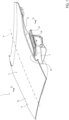
Figure 1 is a partial perspective view of a preferred embodiment of the motor vehicle according to the dictates of this invention, with a hood shown in a lowered, closed position; -
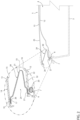
Figure 2 is a cross-section according to a vertical cross-section plane, identified by the line II-II inFigure 1 , i.e. orthogonal to a forward direction of the motor vehicle, with a detail of the cross-section that is also shown on an enlarged scale; -
Figures 3 and 4 are similar to the visible enlarged view inFigure 2 , and illustrate a different embodiment of this invention, according to two possible alternatives; -
Figure 5 is also similar to the enlarged view inFigure 2 , and illustrates a variant regarding the position of a component that is visible in that enlarged view; and -
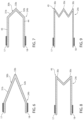
Figures 6 to 9 show, schematically, other variants of the above-mentioned component (since schematised, the images are not exactly to scale, nor do they conform precisely to the previous figures and/or to the actual component). - In
Figure 1 , reference number 1 indicates a motor vehicle (partially illustrated) as a whole. The motor vehicle comprises a body or frame (not illustrated) and abasin 3, which is supported by the body and defines a compartment 4 (Figure 2 ) for housing luggage and objects to transport while travelling. According to variants not illustrated, thecompartment 4 could define an engine compartment (without am appropriate basin, but directly defined by the body). - The motor vehicle 1 also comprises a
hood 5, which is coupled to the body and/or to thebasin 3, in a way not illustrated, so it can rotate between a lowered, closed position, visible inFigure 1 , and a raised, opened position, not illustrated. In the lowered, closed position, thehood 5 closes thecompartment 4 at the top using the interposition ofgaskets 6, schematically illustrated inFigure 2 . - With reference to this figure, the
gaskets 6 are carried in a fixed position by anupper edge 7 of the basin 3 (in the case of an engine compartment, the gaskets are carried in a known way by other components, or directly by the body). - The
hood 5 comprises a supportingskeleton 12 and an outer coveringskin 13, directly or indirectly fixed to theskeleton 12. These two components are preferably made of composite materials with carbon fibres, but according to other variants (for example those shown inFigures 3 and 4 ) they may be made of aluminium alloys. Generally, the material of these components is not an essential element of this invention. - As can be seen in the enlarged view in
Figure 2 , theskin 13 has twosurfaces surface 14 defines part of the outer contour of the motor vehicle 1, while thesurface 15 faces towards theskeleton 12 and is coupled to asurface 16 of thisskeleton 12, preferably by adhesive layers or strips. In this example in this figure, adhesive layers orstrips corresponding side edges skin 13 and of theskeleton 12, along the perimeter of thesurfaces hood 5 is closed, thegaskets 6 rest, to create a seal, against asurface 22 of theskeleton 12 that is opposite thesurface 16, right at theside edge 20. - According to one aspect of this invention, the
hood 5 comprises at least oneplate element 24, which is separate from theskeleton 12 and from theskin 13 and is fixed to theskeleton 12, preferably by glueing. In the case considered inFigure 1 , thehood 5 comprises twoside portions 25, which are opposite and symmetrical to each other in relation to a vertical median plane of symmetry and each one comprises a corresponding element 24 (arranged, thus, along the corresponding side edge of the skeleton 12). - In particular, longitudinally (in a direction parallel to the advancement axis A of the motor vehicle 1) the
elements 24 only extend in a rear, intermediate zone of theside portions 25 of thehood 5. - Again, with reference to
Figure 2 , in this embodiment theelement 24 is arranged between theskeleton 12 and theskin 13 and connects these two components: theelement 24 comprises anend appendage 26 glued to thesurface 15 via theadhesive layer 17 and anotherend appendage 27 glued to thesurface 16 via theadhesive layer 18. - According to one aspect of this invention, the
element 24 comprises adeformable portion 30, which is shaped so as to have a C-shaped cross-section, at least at an intermediate zone of theelement 24; this cross-section consists of: - an
upper wing 31 and alower wing 32, facing and spaced apart from each other, and - an intermediate connecting
portion 33 defined, in particular, by a curved portion, which joins thewings portion 33 horizontally points towards the centre of thehood 5. - Thanks to this C-shaped profile, in substance, the
deformable portion 30 of theelement 24 behaves like a clip spring, which is deformed when thewings skin 13 during an accident, for example a collision with a pedestrian on thesurface 14. In other words, the C-shaped profile of thedeformable portion 30 is such as to dampen the downwards movement of theskin 13, since the deformation consists of an elastic part and a dissipative plastic part, and best absorbs the collision, since thehood 5 succeeds in sinking more than in known solutions. - According to a preferred aspect of this invention, the connecting
portion 33 is less thick than theupper wing 31 andlower wing 32, to optimise the deformation phenomenon during the collision. In particular, the reduction in thickness defines a weakening that leads to concentrating the deformation in the connectingportion 33, to best perform the above-mentioned dampening function and, thus, optimise the absorption of the collision energy. - For example, the connecting
portion 33 has a thickness between 33% and 750 of that of thewings element 24 is made of composite material, i.e. plastic material reinforced with fibres, so that it is produced by overlapping several layers of material, during the manufacturing process: assuming that thewings portion 33 preferably consists of one or two layers (with a thickness equal to approximately 33% and, respectively, 670 of that of thewings 31 and 32); assuming, in contrast, that thewings portion 44 can consist of two or three layers (with a thickness equal to approximately 50% and, respectively, 750 of that of thewings 31 and 32). - In the specific illustrated example, in the cross-section, the
wings portion 33 to theappendages - In addition, in the specific example illustrated, in cross-section, the profile of the
wing 31 has a greater dimension than thewing 32. - The variant of
Figure 5 differs fromFigure 2 due to the fact that theskeleton 12 is arranged between theelement 24 and theskin 13. Therefore, theside edges skin 13 and of theskeleton 12 are directly fixed together (for example, using a single adhesive layer 17), and preferably theappendage 27 defines a lower shoulder where thecorresponding gasket 6 rests to create a seal. - According to a variant, not illustrated, the connecting
portion 33 horizontally points towards the outside, instead of pointing towards the centre of thehood 5. -
Figure 4 shows a different embodiment, advantageous in terms of manufacturing processes when aluminium alloys are used instead of composite materials with carbon fibres. The parts illustrated inFigure 4 are indicated by the same reference numbers used inFigures 2 and5 , where these parts correspond among the various embodiments. - As in
Figure 5 , theside edges skin 13 and of theskeleton 12 are directly fixed to each other (i.e. without intermediate components), according to known methods, preferably by glueing. Theelement 24 is replaced by aplate element 24a and theskeleton 12 is placed between theskin 13 and theelement 24a. The latter comprises alower wing 32a and anappendage 27a, which defines a lower shoulder where thecorresponding gasket 6 rests to create a seal. - In relation to
Figures 2 and5 , theelement 24a comprises anappendage 26a that is arranged at the opposite end in relation to theappendage 27a and is fixed to aportion 40 of theskeleton 12, for example via rivets, nails, glueing, or welding of any type (for hoods made of aluminium alloys or steel). - In this case too, there is a
deformable portion 30a with a C-shaped cross-section, with a similar function to the one of thedeformable portion 30, described above. Thedeformable portion 30a comprises: - the
lower wing 32a of theelement 24a, - an upper wing defined by an
intermediate portion 31a of theskeleton 12, that has opposite ends connected, respectively, to theportion 40 and to theside edge 20, and - an intermediate connecting
portion 33a, which comprises, in turn, theappendage 26a and the portion 40 (with their fastening systems). - In addition, similarly to
Figures 2 and5 , the connectingportion 33a horizontally points towards the centre of thehood 5. - In the variant in
Figure 3 , instead, the situation is the opposite, i.e. the connectingportion 33a points horizontally towards the outside of thehood 5. - In the variants shown in
Figures 6 and 7 , theelement 24 is replaced by anelement 24b wherein the connectingportion 33b has a reduced bending radius and the profile of thewings Figure 7 , then, at the opposite end in relation to the connectingportion 33b, thewings straight portions - In the variants in
Figures 8 and 9 , theelement 24 is replaced by anelement 24c comprising anintermediate portion 45 that has a cross-section with an accordion-like or gusseted contour. Therefore, theintermediate portion 45 consists of a succession of at least twodeformable portions 30c, each having a cross-section with a C-shaped contour. - In use, in the event of an accident where the head of a pedestrian collides against the
skin 13 of thehood 5, thedeformable portions - This absorption function of the collisions is particularly advantageous, in part thanks to the position of the
elements upper wing gaskets 6, when thehood 5 is closed. These components (defined by theedges 7 of thebasin 3, in the specific illustrated case) are relatively rigid, so that they tend to negatively influence the degree of safety in the event of an accident: the presence and position of theelements skin 13 of thehood 5. - The advantages of the
elements skeleton 12, define deformable portions that have a C-shaped cross-section, which are excellent for absorbing energy during a collision, at the resting points defined by thegaskets 6 and by theedges 7 of thebasin 3. - Lastly, it is clear from the foregoing that modifications may be made to the motor vehicle 1, and variations produced thereto, which is described with reference to the appended figures, while remaining within the scope of protection of this invention, as defined in the appended claims included below.
- In particular, the deformable portions and the
corresponding elements - In addition, the contour of the C-shaped cross-section formed from the
deformable portions
Claims (12)
- A motor vehicle (1) comprising:- a front compartment (4);- a hood (5), which, in at least one operating condition, closes said front compartment (4) at the top and comprises:a) a supporting skeleton (12);b) an outer covering skin (13) defining, in use, an outer contour of the motor vehicle and attached directly or indirectly to said supporting skeleton (12);- gaskets (6) carried by at least one support element (7) and placed between said hood (5) and said support element (7) to ensure the seal of said front compartment (4) when closed by said hood (5);wherein said hood (5) comprises at least one deformable portion (30, 30a, 30b), shaped so as to have a C-shaped cross-section and defined by:- an upper wing (31, 31a, 31b) and a lower wing (32, 32b) facing each other, and- a connecting portion (33, 33a) joining said upper and lower wings to each other;wherein said lower wing (32, 32b) forms part of a plate element (24, 24a, 24b, 24c), which is distinct from said supporting skeleton (12) and from said outer covering skin (13), and has one end (27, 26, 26a) coupled to said supporting skeleton (12);wherein said plate element (24, 24a, 24b, 24c) is arranged between said supporting skeleton (12) and said outer covering skin (13), or said supporting skeleton (12) is arranged between said plate element and said outer covering skin (13);and wherein said plate element (24, 24a, 24b, 24c) is arranged vertically aligned with said gaskets (6) and with said support element (7).
- The motor vehicle according to claim 1, wherein said upper wing (31a) is defined by an intermediate portion of said supporting skeleton (12), and said end (26a) constitutes part of said connecting portion (33a).
- The motor vehicle according to claim 1, wherein the entire said deformable portion (30, 30b) constitutes part of said plate element (24, 24b, 24c).
- The motor vehicle according to claim 3, wherein said end (27) is glued to said supporting skeleton (12).
- The motor vehicle according to claim 4, wherein said plate element (24) has a further end (26) glued to said outer covering skin (13).
- The motor vehicle according to any one of claims 3 to 5, wherein said plate element (24c) comprises an accordion-like or gusseted portion (45), in turn comprising said deformable portion (30c).
- The motor vehicle according to any one of claims 3 to 6, wherein said connecting portion (33) has a thickness less than the one of said upper and lower wings (31, 32).
- The motor vehicle according to claim 7, wherein said connecting portion (33) has a thickness between 33% and 750 of the one of said upper and lower wings (31, 32).
- The motor vehicle according to any one of the preceding claims, wherein said connecting portion (33) faces horizontally towards the centre of the hood.
- The motor vehicle according to any one of the preceding claims, wherein said hood (5) has a vertical plane of symmetry and comprises two side portions (25), opposite and symmetrical to each other with respect to said vertical plane of symmetry; and wherein each of said side portions (25) comprises one respective said deformable portion and one respective said plate element.
- The motor vehicle according to any of the previous claims, wherein, when said front compartment (4) is closed by said hood, said gaskets (6) are coupled- to said plate element, if said supporting skeleton (12) is arranged between said plate element and said outer covering skin (13), or- to said supporting skeleton (12), if said plate element is arranged between said supporting skeleton (12) and said outer covering skin (13).
- The motor vehicle according to any of the previous claims, wherein said front compartment (4) is provided for housing luggage and objects to be transported while travelling, and is defined by a front basin (3) supported by a motor vehicle body; said gaskets (6) being carried in a fixed position by an upper edge of said front basin (3), and said upper edge defining said support element (7).
Applications Claiming Priority (1)
| Application Number | Priority Date | Filing Date | Title |
|---|---|---|---|
| IT102023000000042A IT202300000042A1 (en) | 2023-01-04 | 2023-01-04 | MOTOR VEHICLE HOOD |
Publications (1)
| Publication Number | Publication Date |
|---|---|
| EP4397578A1 true EP4397578A1 (en) | 2024-07-10 |
Family
ID=85685776
Family Applications (1)
| Application Number | Title | Priority Date | Filing Date |
|---|---|---|---|
| EP24150163.4A Pending EP4397578A1 (en) | 2023-01-04 | 2024-01-03 | Motor vehicle hood |
Country Status (3)
| Country | Link |
|---|---|
| US (1) | US20240217588A1 (en) |
| EP (1) | EP4397578A1 (en) |
| IT (1) | IT202300000042A1 (en) |
Citations (5)
| Publication number | Priority date | Publication date | Assignee | Title |
|---|---|---|---|---|
| GB2056923A (en) * | 1979-08-23 | 1981-03-25 | Daimler Benz Ag | Motor vehicle having yieldable front body parts |
| US20080122261A1 (en) * | 2006-11-28 | 2008-05-29 | Kyung Dug Seo | Hood of a vehicle |
| EP2239184A1 (en) * | 2008-02-04 | 2010-10-13 | Toyota Jidosha Kabushiki Kaisha | Vehicular hood structure |
| DE102013208275A1 (en) * | 2012-05-11 | 2013-11-28 | GM Global Technology Operations LLC (n. d. Gesetzen des Staates Delaware) | Local limited energy absorber |
| DE202018100293U1 (en) * | 2017-01-20 | 2018-02-01 | Ford Global Technologies, Llc | A hood system |
Family Cites Families (5)
| Publication number | Priority date | Publication date | Assignee | Title |
|---|---|---|---|---|
| GB9824299D0 (en) * | 1998-11-06 | 1998-12-30 | Rover Group | Bonnet assembly for a motor vehicle |
| JP3838125B2 (en) * | 2002-03-15 | 2006-10-25 | 日産自動車株式会社 | Fender structure |
| CN101563267B (en) * | 2007-07-10 | 2011-01-12 | 丰田车体株式会社 | Front structure of car hood |
| US7635157B2 (en) * | 2007-09-11 | 2009-12-22 | GM Global Technology Operation, INC | Vehicle hood assembly with rippled cushion support |
| JP6614191B2 (en) * | 2017-03-30 | 2019-12-04 | トヨタ自動車株式会社 | Vehicle front structure |
-
2023
- 2023-01-04 IT IT102023000000042A patent/IT202300000042A1/en unknown
-
2024
- 2024-01-03 EP EP24150163.4A patent/EP4397578A1/en active Pending
- 2024-01-03 US US18/403,121 patent/US20240217588A1/en active Pending
Patent Citations (6)
| Publication number | Priority date | Publication date | Assignee | Title |
|---|---|---|---|---|
| GB2056923A (en) * | 1979-08-23 | 1981-03-25 | Daimler Benz Ag | Motor vehicle having yieldable front body parts |
| DE2934060A1 (en) * | 1979-08-23 | 1981-03-26 | Daimler-Benz Aktiengesellschaft, 70567 Stuttgart | MOTOR VEHICLE, ESPECIALLY PERSONAL VEHICLES, WITH FLEXIBLE BODY FRONTS |
| US20080122261A1 (en) * | 2006-11-28 | 2008-05-29 | Kyung Dug Seo | Hood of a vehicle |
| EP2239184A1 (en) * | 2008-02-04 | 2010-10-13 | Toyota Jidosha Kabushiki Kaisha | Vehicular hood structure |
| DE102013208275A1 (en) * | 2012-05-11 | 2013-11-28 | GM Global Technology Operations LLC (n. d. Gesetzen des Staates Delaware) | Local limited energy absorber |
| DE202018100293U1 (en) * | 2017-01-20 | 2018-02-01 | Ford Global Technologies, Llc | A hood system |
Also Published As
| Publication number | Publication date |
|---|---|
| US20240217588A1 (en) | 2024-07-04 |
| IT202300000042A1 (en) | 2024-07-04 |
Similar Documents
| Publication | Publication Date | Title |
|---|---|---|
| US6866294B2 (en) | Knee support for motor vehicles | |
| US3936090A (en) | Vehicle door | |
| CN102883942B (en) | The Herba Plantaginis portion of vehicle | |
| CN109109979B (en) | Vehicle front structure and vehicle body module structure | |
| US8919835B1 (en) | Structure for absorbing frontal collision energy of vehicle | |
| EP0855313A1 (en) | Energy absorbing automotive vehicle body structure | |
| KR20190027882A (en) | Automotive exterior panels | |
| JPH0840306A (en) | Pillar structure for absorbing automotive energy | |
| US10384721B2 (en) | Body component | |
| CN113291381A (en) | Car B post additional strengthening and car B post | |
| EP3912840B1 (en) | Automobile door | |
| US4421343A (en) | Knee panel for front seat and knee panel mounting structure for vehicle | |
| JP5151495B2 (en) | Automotive hood stopper structure | |
| EP4397578A1 (en) | Motor vehicle hood | |
| JPH0939833A (en) | Car front pillar | |
| KR20100023346A (en) | Automotive bumper beam unit | |
| US5722715A (en) | Energy absorbing automotive vehicle body structure | |
| JPH07246953A (en) | Occupant protection structure above the car body | |
| US5586797A (en) | Automotive door assembly | |
| GB2553111A (en) | Vehicle upper structure | |
| JP2024504332A (en) | Reinforced parts for vehicles | |
| JP7367555B2 (en) | vehicle hood | |
| US11712949B2 (en) | Automobile side structure and automobile | |
| JP7215498B2 (en) | automobile door | |
| US20240124068A1 (en) | Automobile panel |
Legal Events
| Date | Code | Title | Description |
|---|---|---|---|
| PUAI | Public reference made under article 153(3) epc to a published international application that has entered the european phase |
Free format text: ORIGINAL CODE: 0009012 |
|
| STAA | Information on the status of an ep patent application or granted ep patent |
Free format text: STATUS: THE APPLICATION HAS BEEN PUBLISHED |
|
| AK | Designated contracting states |
Kind code of ref document: A1 Designated state(s): AL AT BE BG CH CY CZ DE DK EE ES FI FR GB GR HR HU IE IS IT LI LT LU LV MC ME MK MT NL NO PL PT RO RS SE SI SK SM TR |
|
| STAA | Information on the status of an ep patent application or granted ep patent |
Free format text: STATUS: REQUEST FOR EXAMINATION WAS MADE |
|
| 17P | Request for examination filed |
Effective date: 20241204 |
|
| RBV | Designated contracting states (corrected) |
Designated state(s): AL AT BE BG CH CY CZ DE DK EE ES FI FR GB GR HR HU IE IS IT LI LT LU LV MC ME MK MT NL NO PL PT RO RS SE SI SK SM TR |
|
| STAA | Information on the status of an ep patent application or granted ep patent |
Free format text: STATUS: EXAMINATION IS IN PROGRESS |
|
| 17Q | First examination report despatched |
Effective date: 20250513 |