EP4397557A1 - Vehicle and method of controlling the same - Google Patents
Vehicle and method of controlling the same Download PDFInfo
- Publication number
- EP4397557A1 EP4397557A1 EP23210493.5A EP23210493A EP4397557A1 EP 4397557 A1 EP4397557 A1 EP 4397557A1 EP 23210493 A EP23210493 A EP 23210493A EP 4397557 A1 EP4397557 A1 EP 4397557A1
- Authority
- EP
- European Patent Office
- Prior art keywords
- target vehicle
- detection position
- vehicle
- warning
- distance
- Prior art date
- Legal status (The legal status is an assumption and is not a legal conclusion. Google has not performed a legal analysis and makes no representation as to the accuracy of the status listed.)
- Granted
Links
Images




Classifications
-
- B—PERFORMING OPERATIONS; TRANSPORTING
- B60—VEHICLES IN GENERAL
- B60W—CONJOINT CONTROL OF VEHICLE SUB-UNITS OF DIFFERENT TYPE OR DIFFERENT FUNCTION; CONTROL SYSTEMS SPECIALLY ADAPTED FOR HYBRID VEHICLES; ROAD VEHICLE DRIVE CONTROL SYSTEMS FOR PURPOSES NOT RELATED TO THE CONTROL OF A PARTICULAR SUB-UNIT
- B60W40/00—Estimation or calculation of non-directly measurable driving parameters for road vehicle drive control systems not related to the control of a particular sub unit, e.g. by using mathematical models
- B60W40/02—Estimation or calculation of non-directly measurable driving parameters for road vehicle drive control systems not related to the control of a particular sub unit, e.g. by using mathematical models related to ambient conditions
- B60W40/04—Traffic conditions
-
- B—PERFORMING OPERATIONS; TRANSPORTING
- B60—VEHICLES IN GENERAL
- B60W—CONJOINT CONTROL OF VEHICLE SUB-UNITS OF DIFFERENT TYPE OR DIFFERENT FUNCTION; CONTROL SYSTEMS SPECIALLY ADAPTED FOR HYBRID VEHICLES; ROAD VEHICLE DRIVE CONTROL SYSTEMS FOR PURPOSES NOT RELATED TO THE CONTROL OF A PARTICULAR SUB-UNIT
- B60W30/00—Purposes of road vehicle drive control systems not related to the control of a particular sub-unit, e.g. of systems using conjoint control of vehicle sub-units
- B60W30/08—Active safety systems predicting or avoiding probable or impending collision or attempting to minimise its consequences
- B60W30/095—Predicting travel path or likelihood of collision
-
- B—PERFORMING OPERATIONS; TRANSPORTING
- B60—VEHICLES IN GENERAL
- B60Q—ARRANGEMENT OF SIGNALLING OR LIGHTING DEVICES, THE MOUNTING OR SUPPORTING THEREOF OR CIRCUITS THEREFOR, FOR VEHICLES IN GENERAL
- B60Q9/00—Arrangement or adaptation of signal devices not provided for in one of main groups B60Q1/00 - B60Q7/00, e.g. haptic signalling
- B60Q9/008—Arrangement or adaptation of signal devices not provided for in one of main groups B60Q1/00 - B60Q7/00, e.g. haptic signalling for anti-collision purposes
-
- B—PERFORMING OPERATIONS; TRANSPORTING
- B60—VEHICLES IN GENERAL
- B60K—ARRANGEMENT OR MOUNTING OF PROPULSION UNITS OR OF TRANSMISSIONS IN VEHICLES; ARRANGEMENT OR MOUNTING OF PLURAL DIVERSE PRIME-MOVERS IN VEHICLES; AUXILIARY DRIVES FOR VEHICLES; INSTRUMENTATION OR DASHBOARDS FOR VEHICLES; ARRANGEMENTS IN CONNECTION WITH COOLING, AIR INTAKE, GAS EXHAUST OR FUEL SUPPLY OF PROPULSION UNITS IN VEHICLES
- B60K35/00—Instruments specially adapted for vehicles; Arrangement of instruments in or on vehicles
-
- B—PERFORMING OPERATIONS; TRANSPORTING
- B60—VEHICLES IN GENERAL
- B60R—VEHICLES, VEHICLE FITTINGS, OR VEHICLE PARTS, NOT OTHERWISE PROVIDED FOR
- B60R16/00—Electric or fluid circuits specially adapted for vehicles and not otherwise provided for; Arrangement of elements of electric or fluid circuits specially adapted for vehicles and not otherwise provided for
- B60R16/02—Electric or fluid circuits specially adapted for vehicles and not otherwise provided for; Arrangement of elements of electric or fluid circuits specially adapted for vehicles and not otherwise provided for electric constitutive elements
- B60R16/023—Electric or fluid circuits specially adapted for vehicles and not otherwise provided for; Arrangement of elements of electric or fluid circuits specially adapted for vehicles and not otherwise provided for electric constitutive elements for transmission of signals between vehicle parts or subsystems
- B60R16/0231—Circuits relating to the driving or the functioning of the vehicle
- B60R16/0232—Circuits relating to the driving or the functioning of the vehicle for measuring vehicle parameters and indicating critical, abnormal or dangerous conditions
-
- B—PERFORMING OPERATIONS; TRANSPORTING
- B60—VEHICLES IN GENERAL
- B60W—CONJOINT CONTROL OF VEHICLE SUB-UNITS OF DIFFERENT TYPE OR DIFFERENT FUNCTION; CONTROL SYSTEMS SPECIALLY ADAPTED FOR HYBRID VEHICLES; ROAD VEHICLE DRIVE CONTROL SYSTEMS FOR PURPOSES NOT RELATED TO THE CONTROL OF A PARTICULAR SUB-UNIT
- B60W50/00—Details of control systems for road vehicle drive control not related to the control of a particular sub-unit, e.g. process diagnostic or vehicle driver interfaces
- B60W50/06—Improving the dynamic response of the control system, e.g. improving the speed of regulation or avoiding hunting or overshoot
-
- B—PERFORMING OPERATIONS; TRANSPORTING
- B60—VEHICLES IN GENERAL
- B60W—CONJOINT CONTROL OF VEHICLE SUB-UNITS OF DIFFERENT TYPE OR DIFFERENT FUNCTION; CONTROL SYSTEMS SPECIALLY ADAPTED FOR HYBRID VEHICLES; ROAD VEHICLE DRIVE CONTROL SYSTEMS FOR PURPOSES NOT RELATED TO THE CONTROL OF A PARTICULAR SUB-UNIT
- B60W50/00—Details of control systems for road vehicle drive control not related to the control of a particular sub-unit, e.g. process diagnostic or vehicle driver interfaces
- B60W50/08—Interaction between the driver and the control system
- B60W50/14—Means for informing the driver, warning the driver or prompting a driver intervention
-
- G—PHYSICS
- G08—SIGNALLING
- G08G—TRAFFIC CONTROL SYSTEMS
- G08G1/00—Traffic control systems for road vehicles
- G08G1/16—Anti-collision systems
-
- B—PERFORMING OPERATIONS; TRANSPORTING
- B60—VEHICLES IN GENERAL
- B60W—CONJOINT CONTROL OF VEHICLE SUB-UNITS OF DIFFERENT TYPE OR DIFFERENT FUNCTION; CONTROL SYSTEMS SPECIALLY ADAPTED FOR HYBRID VEHICLES; ROAD VEHICLE DRIVE CONTROL SYSTEMS FOR PURPOSES NOT RELATED TO THE CONTROL OF A PARTICULAR SUB-UNIT
- B60W50/00—Details of control systems for road vehicle drive control not related to the control of a particular sub-unit, e.g. process diagnostic or vehicle driver interfaces
- B60W2050/0062—Adapting control system settings
- B60W2050/0075—Automatic parameter input, automatic initialising or calibrating means
- B60W2050/0083—Setting, resetting, calibration
- B60W2050/0085—Setting or resetting initial positions
-
- B—PERFORMING OPERATIONS; TRANSPORTING
- B60—VEHICLES IN GENERAL
- B60W—CONJOINT CONTROL OF VEHICLE SUB-UNITS OF DIFFERENT TYPE OR DIFFERENT FUNCTION; CONTROL SYSTEMS SPECIALLY ADAPTED FOR HYBRID VEHICLES; ROAD VEHICLE DRIVE CONTROL SYSTEMS FOR PURPOSES NOT RELATED TO THE CONTROL OF A PARTICULAR SUB-UNIT
- B60W50/00—Details of control systems for road vehicle drive control not related to the control of a particular sub-unit, e.g. process diagnostic or vehicle driver interfaces
- B60W50/08—Interaction between the driver and the control system
- B60W50/14—Means for informing the driver, warning the driver or prompting a driver intervention
- B60W2050/143—Alarm means
-
- B—PERFORMING OPERATIONS; TRANSPORTING
- B60—VEHICLES IN GENERAL
- B60W—CONJOINT CONTROL OF VEHICLE SUB-UNITS OF DIFFERENT TYPE OR DIFFERENT FUNCTION; CONTROL SYSTEMS SPECIALLY ADAPTED FOR HYBRID VEHICLES; ROAD VEHICLE DRIVE CONTROL SYSTEMS FOR PURPOSES NOT RELATED TO THE CONTROL OF A PARTICULAR SUB-UNIT
- B60W2554/00—Input parameters relating to objects
- B60W2554/40—Dynamic objects, e.g. animals, windblown objects
- B60W2554/404—Characteristics
- B60W2554/4041—Position
-
- B—PERFORMING OPERATIONS; TRANSPORTING
- B60—VEHICLES IN GENERAL
- B60W—CONJOINT CONTROL OF VEHICLE SUB-UNITS OF DIFFERENT TYPE OR DIFFERENT FUNCTION; CONTROL SYSTEMS SPECIALLY ADAPTED FOR HYBRID VEHICLES; ROAD VEHICLE DRIVE CONTROL SYSTEMS FOR PURPOSES NOT RELATED TO THE CONTROL OF A PARTICULAR SUB-UNIT
- B60W2554/00—Input parameters relating to objects
- B60W2554/40—Dynamic objects, e.g. animals, windblown objects
- B60W2554/404—Characteristics
- B60W2554/4044—Direction of movement, e.g. backwards
-
- B—PERFORMING OPERATIONS; TRANSPORTING
- B60—VEHICLES IN GENERAL
- B60W—CONJOINT CONTROL OF VEHICLE SUB-UNITS OF DIFFERENT TYPE OR DIFFERENT FUNCTION; CONTROL SYSTEMS SPECIALLY ADAPTED FOR HYBRID VEHICLES; ROAD VEHICLE DRIVE CONTROL SYSTEMS FOR PURPOSES NOT RELATED TO THE CONTROL OF A PARTICULAR SUB-UNIT
- B60W2554/00—Input parameters relating to objects
- B60W2554/80—Spatial relation or speed relative to objects
-
- B—PERFORMING OPERATIONS; TRANSPORTING
- B60—VEHICLES IN GENERAL
- B60W—CONJOINT CONTROL OF VEHICLE SUB-UNITS OF DIFFERENT TYPE OR DIFFERENT FUNCTION; CONTROL SYSTEMS SPECIALLY ADAPTED FOR HYBRID VEHICLES; ROAD VEHICLE DRIVE CONTROL SYSTEMS FOR PURPOSES NOT RELATED TO THE CONTROL OF A PARTICULAR SUB-UNIT
- B60W2554/00—Input parameters relating to objects
- B60W2554/80—Spatial relation or speed relative to objects
- B60W2554/801—Lateral distance
-
- B—PERFORMING OPERATIONS; TRANSPORTING
- B60—VEHICLES IN GENERAL
- B60W—CONJOINT CONTROL OF VEHICLE SUB-UNITS OF DIFFERENT TYPE OR DIFFERENT FUNCTION; CONTROL SYSTEMS SPECIALLY ADAPTED FOR HYBRID VEHICLES; ROAD VEHICLE DRIVE CONTROL SYSTEMS FOR PURPOSES NOT RELATED TO THE CONTROL OF A PARTICULAR SUB-UNIT
- B60W2554/00—Input parameters relating to objects
- B60W2554/80—Spatial relation or speed relative to objects
- B60W2554/802—Longitudinal distance
-
- B—PERFORMING OPERATIONS; TRANSPORTING
- B60—VEHICLES IN GENERAL
- B60W—CONJOINT CONTROL OF VEHICLE SUB-UNITS OF DIFFERENT TYPE OR DIFFERENT FUNCTION; CONTROL SYSTEMS SPECIALLY ADAPTED FOR HYBRID VEHICLES; ROAD VEHICLE DRIVE CONTROL SYSTEMS FOR PURPOSES NOT RELATED TO THE CONTROL OF A PARTICULAR SUB-UNIT
- B60W2554/00—Input parameters relating to objects
- B60W2554/80—Spatial relation or speed relative to objects
- B60W2554/805—Azimuth angle
-
- B—PERFORMING OPERATIONS; TRANSPORTING
- B60—VEHICLES IN GENERAL
- B60W—CONJOINT CONTROL OF VEHICLE SUB-UNITS OF DIFFERENT TYPE OR DIFFERENT FUNCTION; CONTROL SYSTEMS SPECIALLY ADAPTED FOR HYBRID VEHICLES; ROAD VEHICLE DRIVE CONTROL SYSTEMS FOR PURPOSES NOT RELATED TO THE CONTROL OF A PARTICULAR SUB-UNIT
- B60W2554/00—Input parameters relating to objects
- B60W2554/80—Spatial relation or speed relative to objects
- B60W2554/806—Relative heading
-
- B—PERFORMING OPERATIONS; TRANSPORTING
- B60—VEHICLES IN GENERAL
- B60W—CONJOINT CONTROL OF VEHICLE SUB-UNITS OF DIFFERENT TYPE OR DIFFERENT FUNCTION; CONTROL SYSTEMS SPECIALLY ADAPTED FOR HYBRID VEHICLES; ROAD VEHICLE DRIVE CONTROL SYSTEMS FOR PURPOSES NOT RELATED TO THE CONTROL OF A PARTICULAR SUB-UNIT
- B60W30/00—Purposes of road vehicle drive control systems not related to the control of a particular sub-unit, e.g. of systems using conjoint control of vehicle sub-units
- B60W30/08—Active safety systems predicting or avoiding probable or impending collision or attempting to minimise its consequences
- B60W30/095—Predicting travel path or likelihood of collision
- B60W30/0953—Predicting travel path or likelihood of collision the prediction being responsive to vehicle dynamic parameters
-
- B—PERFORMING OPERATIONS; TRANSPORTING
- B60—VEHICLES IN GENERAL
- B60W—CONJOINT CONTROL OF VEHICLE SUB-UNITS OF DIFFERENT TYPE OR DIFFERENT FUNCTION; CONTROL SYSTEMS SPECIALLY ADAPTED FOR HYBRID VEHICLES; ROAD VEHICLE DRIVE CONTROL SYSTEMS FOR PURPOSES NOT RELATED TO THE CONTROL OF A PARTICULAR SUB-UNIT
- B60W30/00—Purposes of road vehicle drive control systems not related to the control of a particular sub-unit, e.g. of systems using conjoint control of vehicle sub-units
- B60W30/08—Active safety systems predicting or avoiding probable or impending collision or attempting to minimise its consequences
- B60W30/095—Predicting travel path or likelihood of collision
- B60W30/0956—Predicting travel path or likelihood of collision the prediction being responsive to traffic or environmental parameters
-
- B—PERFORMING OPERATIONS; TRANSPORTING
- B60—VEHICLES IN GENERAL
- B60Y—INDEXING SCHEME RELATING TO ASPECTS CROSS-CUTTING VEHICLE TECHNOLOGY
- B60Y2400/00—Special features of vehicle units
- B60Y2400/90—Driver alarms
Definitions
- the vehicle M may activate a rear cross-traffic alert function and control whether to send a warning of a collision with the target vehicle T based on the detection information such as a position and velocity of the target vehicle T detected by the sensing part in the state in which the rear cross-traffic alert function is activated.
- the vehicle M may send the warning of a collision with the target vehicle T.
- the conditions required to send a warning of a collision may include a condition in which the position of the target vehicle T needs to be within a region of a warning of a collision, a condition in which an approach angle ⁇ of the target vehicle T needs to be a preset angle or less, a condition in which the time-to-collision (TTC) between the vehicle M and the target vehicle T needs to be a predetermined time or less, and a condition in which a predicted position of a collision (impact point (IP)) between the vehicle M and the target vehicle T needs to be present in a preset region.
- TTC time-to-collision
- IP impact point
- the present disclosure is not necessarily limited thereto.
- the condition in which the approach angle ⁇ needs to be the preset angle or less may be set to prevent an erroneous warning against the target vehicle T that approaches the vehicle in an X-axis direction.
- the approach angle ⁇ of the target vehicle T may be determined based on an X-axis velocity V x and a Y-axis velocity V y of the target vehicle T based on Equation 1 below.
- ⁇ tan ⁇ 1 V x V y
- the predicted position of a collision (IP) between the vehicle M and the target vehicle T may be determined based on Equation 2 below.
- X a and Y a may be respectively an X-axis coordinate and a Y-axis coordinate with respect to a current detection position of the target vehicle T detected by the sensing part of the vehicle M.
- IP ⁇ V x V y Y a + X a
- TTC time-to-collision
- the approach angle ⁇ of the target vehicle T may be used to determine X c and Y c by compensating for the X-axis coordinate X a and the Y-axis coordinate Y a with respect to the current detection position of the target vehicle T.
- X c Y c cos ⁇ ⁇ sin ⁇ sin ⁇ cos ⁇ X a Y a
- the approach angle ⁇ of the target vehicle T may be used to determine V xc and V yc by compensating for the X-axis velocity V x and the Y-axis velocity V y of the target vehicle T.
- X xc Y yc cos ⁇ ⁇ sin ⁇ sin ⁇ cos ⁇ V x V y
- ⁇ c may be determined by compensating for the approach angle ⁇ of the target vehicle T based on Equation 6 and IP c may be determined by compensating for the predicted position of a collision (IP) based on Equation 7.
- IP predicted position of a collision
- the errors of the X-axis velocity V x and the Y-axis velocity V y may increase in case that the detection accuracy of the rear radar sensor deteriorates because multiple reflection points are formed with respect to the target vehicle or a small position error increases to a large velocity error.
- the vehicle M may sequentially set an initial detection position (X init , Y init ) and a subsequent detection position (X k , Y k ) of the target vehicle T by detecting the position of the target vehicle T by using the sensing part and determine the approach angle ⁇ k_recalc of the target vehicle T and the predicted position of a collision (IP k_recalc between the vehicle M and the target vehicle T based on the initial detection position (X init , Y init ) and the subsequent detection position (X k , Y k ).
- X init and Y init may correspond to the X-axis coordinate and the Y-axis coordinate of the initial detection position of the target vehicle T
- X k and Y k may correspond to the X-axis coordinate and the Y-axis coordinate of the subsequent detection position of the target vehicle T.
- the vehicle M may detect a movement of the target vehicle T from the right side of the vehicle M to the left side of the vehicle M and send a warning of a collision. Therefore, the vehicle M may set the current detection position of the target vehicle T to the initial detection position when the target vehicle T is present in the region of the warning of a collision in a state in which a Y-axis velocity V y of the target vehicle T is lower than '0'.
- the vehicle M may determine the approach angle ( ⁇ k_recalc ) and the predicted position of a collision (IP k_recalc ) based on the initial detection position (X init , Y init ) and the subsequent detection position (X k , Y k ) and control whether to send a warning of a collision based on the approach angle ( ⁇ k_recalc ) and the predicted position of a collision (IP k_recalc ).
- the vehicle M may control whether to send a warning of a collision depending on whether the approach angle ( ⁇ k_recalc ) is a preset angle or smaller and whether the predicted position of a collision (IP k_recalc ) is present in a preset region.
- the approach angle ( ⁇ k_recalc ) is set to an angle between a line, which connects the initial detection position and the subsequent detection position of the target vehicle T, and a reference line (Y-axis) of the vehicle.
- the vehicle M may set the approach angle ( ⁇ k_recalc ) based on Equation 11 below.
- ⁇ k recalc tan ⁇ 1 X k ⁇ X init Y k ⁇ Y init
- IP k_recalc The predicted position of a collision (IP k_recalc ) may be determined based on Equation 12 below.
- IP k _ recalc ⁇ X k ⁇ X init Y k ⁇ Y init Y k + X k
- the vehicle M may select and use one of the approach angle ( ⁇ in FIG. 2 ), the compensated approach angle ( ⁇ c in FIG. 2 ), and the approach angle ( ⁇ k_recalc ) to determine whether to send a warning of a collision and select and use the predicted position of a collision (IP in FIG. 2 ), the compensated predicted position of a collision (IP c ) in FIG. 2 ), and the predicted position of a collision (IP k_reclac ) to determine whether to send a warning of a collision.
- IP in FIG. 2 the compensated predicted position of a collision
- IP c compensated predicted position of a collision
- IP k_reclac the predicted position of a collision
- the vehicle M may reset the current detection position of the target vehicle T to the initial detection position of the target vehicle T by periodically monitoring a route of the target vehicle T in order to prepare for a case in which a route through which the target vehicle T approaches the vehicle M is changed.
- the vehicle M may determine a route tracking angle ( ⁇ k_pathcalc ) of the target vehicle T in case that the current detection distance (R a ) of the target vehicle T is smaller than a distance made by subtracting a preset monitoring distance (R pathcheck_thr ) from a route tracking start distance R pathcheck of the target vehicle T.
- the route tracking start distance T pathcheck may correspond to a distance between the route tracking start position of the target vehicle T and the position of the vehicle M, and an initial value may be set to the initial detection distance (R init ) of the target vehicle T.
- the vehicle M may determine that the movement route of the target vehicle T is changed in case that a difference between the route tracking angle ( ⁇ k_pathcalc ) and the approach angle ( ⁇ k_recalc ) is a preset critical angle ( ⁇ reset_thr ) or larger.
- ⁇ k _ pathcalc ⁇ ⁇ k _ recalc > ⁇ reset _ thr
- the vehicle M may reset the current detection position of the target vehicle T to the initial detection position of the target vehicle T and set and store the current detection position of the target vehicle T as the route tracking start position of the target vehicle T.
- the warning-sending control part 200 of the vehicle may sequentially set the initial detection position (X init , Y init ) and the subsequent detection position (X k , Y k ) of the target vehicle based on the sensing data (S102 and S103).
Landscapes
- Engineering & Computer Science (AREA)
- Automation & Control Theory (AREA)
- Mechanical Engineering (AREA)
- Transportation (AREA)
- Human Computer Interaction (AREA)
- Physics & Mathematics (AREA)
- General Physics & Mathematics (AREA)
- Mathematical Physics (AREA)
- Chemical & Material Sciences (AREA)
- Combustion & Propulsion (AREA)
- Traffic Control Systems (AREA)
Abstract
Description
- The present disclosure relates to a vehicle and a method of controlling the same, which improve the accuracy of a warning of a collision with a target vehicle that approaches a vehicle.
- An advanced driver assistance system (ADAS) refers to a technology that allows a vehicle to autonomously recognize and determine some of many situations, which may occur while the vehicle travels, and control mechanical devices in the vehicle. The functions related to autonomous driving are being ultimately developed.
- The ADAS system may provide a rear side warning function such as a rear cross-traffic alert (RCTA) and a door open warning (DOW). The rear side warning function detects whether a target vehicle, which is detected by rear radar sensors, approaches left and right sides of the vehicle. The rear side warning function sends a warning of a collision with the target vehicle depending on the detection result.
- In this case, in order to determine whether to send a warning of a collision with the target vehicle, the ADAS system may consider an approach angle of the target vehicle, a predicted position of a collision with the target vehicle, and the like. In general, the ADAS system determines an approach angle of the target vehicle and a predicted position of a collision with the target vehicle based on a longitudinal velocity and a transverse velocity of the target vehicle. However, in case that an error related to the velocity of the target vehicle increases, errors related to the approach angle and the predicted position of a collision also increase, which may degrade the accuracy of a warning of a collision.
- In case that the accuracy of the warning of a collision is degraded, an erroneous warning situation may occur in which a warning of a collision is sent in a situation in which the warning of a collision is not required. Further, a non-warning situation may occur in which a warning of a collision is not sent in a situation in which the warning of a collision is required.
- The foregoing explained as the background is intended merely to aid in the understanding of the background of the present disclosure, and is not intended to mean that the present disclosure falls within the purview of the related art that is already known to those skilled in the art.
- Accordingly, the present disclosure has been made keeping in mind the above problems occurring in the related art, and the present disclosure is intended to provide a vehicle and a method of controlling the same, which improve accuracy of a warning of a collision by determining an approach angle of a target vehicle and a predicted position of a collision based on a position of a target vehicle detected by a radar sensor and controlling whether to send a warning of a collision with the target vehicle based on the determination result.
- Technical problems to be solved by the present disclosure are not limited to the above-mentioned technical problems, and other technical problems, which are not mentioned above, may be clearly understood from the following descriptions by those skilled in the art to which the present disclosure pertains.
- According to one aspect, there is provided a method of controlling a vehicle, the method including: detecting a position of a target vehicle and sequentially setting an initial detection position and a subsequent detection position of the target vehicle; determining an approach angle of the target vehicle based on the initial detection position and the subsequent detection position; and controlling whether to send a warning of a collision based on the approach angle.
- According to one aspect, there is provided a vehicle including: a sensing part configured to detect a position of a target vehicle and output sensing data; and a warning-sending control part configured to sequentially set an initial detection position and a subsequent detection position of the target vehicle based on the sensing data, determine an approach angle of the target vehicle based on the initial detection position and the subsequent detection position, and control whether to send a warning of a collision depending on the approach angle.
- According to the present disclosure, it is possible to improve the accuracy of a warning of a collision by determining the approach angle of the target vehicle and the predicted position of a collision based on a position of a target vehicle detected by the radar sensor and controlling whether to send a warning of a collision with the target vehicle based on the determination result.
- The effects capable of being obtained by the present disclosure are not limited to the aforementioned effects, and other effects, which are not mentioned above, will be clearly understood by those skilled in the art from the following description.
-
-
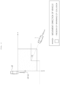
FIG. 1 is a block diagram illustrating a configuration of a vehicle according to an embodiment of the present disclosure. -
FIG. 2 is a view for explaining a process in which the vehicle according to the embodiment of the present disclosure controls whether to send a warning of a collision based on a velocity of a target vehicle. -
FIG. 3 is a view for explaining a process in which the vehicle according to the embodiment of the present disclosure controls whether to send a warning of a collision based on a position of the target vehicle. -
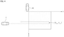
FIG. 4 is a view for explaining a process in which the vehicle according to the embodiment of the present disclosure sets an initial detection position of the target vehicle. -
FIG. 5 is a view for explaining a process in which the vehicle according to the embodiment of the present disclosure monitors a movement route of the target vehicle. -
FIG. 6 is a flowchart for explaining a method of controlling the vehicle according to the embodiment of the present disclosure. - Hereinafter, embodiments disclosed in the present specification will be described in detail with reference to the accompanying drawings. The same or similar constituent elements are assigned with the same reference numerals regardless of reference numerals, and the repetitive description thereof will be omitted.
- In the description of the embodiments disclosed in the present specification, the specific descriptions of publicly known related technologies will be omitted when it is determined that the specific descriptions may obscure the subject matter of the embodiments disclosed in the present specification. In addition, it should be interpreted that the accompanying drawings are provided only to allow those skilled in the art to easily understand the embodiments disclosed in the present specification, and the technical spirit disclosed in the present specification is not limited by the accompanying drawings, and includes all alterations, equivalents, and alternatives that are included in the spirit and the technical scope of the present disclosure.
- The terms including ordinal numbers such as "first," "second," and the like may be used to describe various constituent elements, but the constituent elements are not limited by the terms. These terms are used only to distinguish one constituent element from another constituent element.
- Singular expressions include plural expressions unless clearly described as different meanings in the context.
- In the present specification, it should be understood the terms "comprises," "comprising," "includes," "including," "containing," "has," "having" or other variations thereof are inclusive and therefore specify the presence of stated features, integers, steps, operations, elements, components, or combinations thereof, but do not preclude the presence or addition of one or more other features, integers, steps, operations, elements, components, or combinations thereof.
- In addition, the term "control unit" or "unit" included in the name of "motor control unit (MCU)" is merely a term widely used to name a control device (controller or control unit) for controlling a particular vehicle function but does not mean a generic function unit. For example, the control unit may include a communication device configured to communicate with another control unit or a sensor to control a corresponding function, a memory configured to store an operating system, a logic command, and input/output information, and one or more processors configured to perform determination, computation, decision, or the like required to control the corresponding function.
-
FIG. 1 is a block diagram illustrating a configuration of a vehicle according to an embodiment of the present disclosure. - As illustrated in
FIG. 1 , the vehicle may include asensing part 100 and a warning-sending control part 200. An advanced driver assistance system (ADAS) or an autonomous driving system may be applied to the vehicle according to the present embodiment. - The
sensing part 100 may detect a position, a velocity, and the like of a target vehicle, which approaches the vehicle, and output sensing data. In the present embodiment, thesensing part 100 may be implemented as a radar sensor provided at a rear side of the vehicle. However, the present disclosure is not necessarily limited thereto. - The warning-sending
control part 200 may determine whether the vehicle and the target vehicle collide with each other based on the sensing data outputted from thesensing part 100. The warning-sendingcontrol part 200 may control whether to send a warning of a collision with the target vehicle based on the determination result. For example, in case that the warning-sendingcontrol part 200 determines that the vehicle will collide with the target vehicle, the warning-sendingcontrol part 200 may perform control to send a warning of a collision through a display or the like so that a driver recognizes the warning. Further, the warning-sendingcontrol part 200 may perform control to perform emergency braking, door locking, or the like on the vehicle. -
FIG. 2 is a view for explaining a process in which the vehicle according to the embodiment of the present disclosure controls whether to send a warning of a collision based on a velocity of the target vehicle. - With reference to
FIG. 2 , a vehicle M corresponds to a vehicle including the constituent elements inFIG. 1 . A target vehicle T is a vehicle detected by the sensing part of the vehicle M. - When the vehicle M is at the R shift position (i.e., the vehicle M moves rearward), the vehicle M may activate a rear cross-traffic alert function and control whether to send a warning of a collision with the target vehicle T based on the detection information such as a position and velocity of the target vehicle T detected by the sensing part in the state in which the rear cross-traffic alert function is activated.
- In case that for the conditions required to send the warning of a collision are satisfied, the vehicle M may send the warning of a collision with the target vehicle T. The conditions required to send a warning of a collision may include a condition in which the position of the target vehicle T needs to be within a region of a warning of a collision, a condition in which an approach angle θ of the target vehicle T needs to be a preset angle or less, a condition in which the time-to-collision (TTC) between the vehicle M and the target vehicle T needs to be a predetermined time or less, and a condition in which a predicted position of a collision (impact point (IP)) between the vehicle M and the target vehicle T needs to be present in a preset region. However, the present disclosure is not necessarily limited thereto. In this case, the condition in which the approach angle θ needs to be the preset angle or less may be set to prevent an erroneous warning against the target vehicle T that approaches the vehicle in an X-axis direction.
- The approach angle θ of the target vehicle T may be determined based on an X-axis velocity Vx and a Y-axis velocity Vy of the target vehicle T based on Equation 1 below.

- The predicted position of a collision (IP) between the vehicle M and the target vehicle T may be determined based on Equation 2 below. Here, Xa and Ya may be respectively an X-axis coordinate and a Y-axis coordinate with respect to a current detection position of the target vehicle T detected by the sensing part of the vehicle M.

- The time-to-collision (TTC) between the vehicle M and the target vehicle T may be determined based on Equation 3 below.

- Meanwhile, as shown in Equation 4 below, the approach angle θ of the target vehicle T may be used to determine Xc and Yc by compensating for the X-axis coordinate Xa and the Y-axis coordinate Ya with respect to the current detection position of the target vehicle T.

- In addition, as shown in Equation 5 below, the approach angle θ of the target vehicle T may be used to determine Vxc and Vyc by compensating for the X-axis velocity Vx and the Y-axis velocity Vy of the target vehicle T.

- By using Xc, Yc, Vxc, and Vyc determined based on Equations 4 and 5, θc may be determined by compensating for the approach angle θ of the target vehicle T based on Equation 6 and IPc may be determined by compensating for the predicted position of a collision (IP) based on Equation 7.


- Therefore, the vehicle M may select and use one of the approach angle θ and the compensated approach angle θc to determine whether to send a warning of a collision and select and use one of the predicted position of a collision (IP) and the compensated predicted position of a collision (IPc) to determine whether to send the warning of a collision.
- As described above, the vehicle M may determine the approach angle θ of the target vehicle T and the predicted position of a collision (IP) with the target vehicle T based on the X-axis velocity Vc and the Y-axis velocity Vy of the target vehicle T and control whether to send a warning of a collision based on the determination result.
- However, in case that an error with respect to the X-axis velocity Vx and the Y-axis velocity Vy increases, errors of the approach angle θ and the predicted position of a collision (IP) increase, which may degrade the accuracy of the warning of a collision sent by the vehicle M. In more detail, the errors of the X-axis velocity Vx and the Y-axis velocity Vy may increase in case that the detection accuracy of the rear radar sensor deteriorates because multiple reflection points are formed with respect to the target vehicle or a small position error increases to a large velocity error.
- Therefore, the present embodiment proposes the configuration that improves the accuracy of a warning of a collision by determining the approach angle of the target vehicle and the predicted position of a collision based on the position of the target vehicle and controlling whether to send the warning of a collision with the target vehicle based on the determination result.
-
FIG. 3 is a view for explaining a process in which the vehicle according to the embodiment of the present disclosure controls whether to send a warning of a collision based on a position of the target vehicle. - With reference to
FIG. 3 , the vehicle M may sequentially set an initial detection position (Xinit, Yinit) and a subsequent detection position (Xk, Yk) of the target vehicle T by detecting the position of the target vehicle T by using the sensing part and determine the approach angle θk_recalc of the target vehicle T and the predicted position of a collision (IPk_recalc between the vehicle M and the target vehicle T based on the initial detection position (Xinit, Yinit) and the subsequent detection position (Xk, Yk). Here, Xinit and Yinit may correspond to the X-axis coordinate and the Y-axis coordinate of the initial detection position of the target vehicle T, and Xk and Yk may correspond to the X-axis coordinate and the Y-axis coordinate of the subsequent detection position of the target vehicle T. - The initial detection position (Xinit, Yinit) may be determined depending on a movement direction of the target vehicle T detected by the sensing part of the vehicle M. More specifically, the vehicle M may determine the movement direction of the target vehicle T based on the velocity of the target vehicle T detected by the sensing part and set the current detection position of the target vehicle T to the initial detection position (Xinit, Yinit) when the target vehicle T is present within the region of the warning of a collision in the state in which the movement direction of the target vehicle T is a preset movement direction.
FIG. 4 illustrates a process in which the vehicle M sets the initial detection position of the target vehicle T. In this case, it is assumed that the rear radar sensor is disposed at a rear right side of the vehicle M. In this case, the vehicle M may detect a movement of the target vehicle T from the right side of the vehicle M to the left side of the vehicle M and send a warning of a collision. Therefore, the vehicle M may set the current detection position of the target vehicle T to the initial detection position when the target vehicle T is present in the region of the warning of a collision in a state in which a Y-axis velocity Vy of the target vehicle T is lower than '0'. - With reference back to
FIG. 3 , the vehicle M may set the current detection position (Xa, Ya) of the target vehicle T to the subsequent detection position (Xk, Yk) of the target vehicle T when a current detection distance (Ra of the target vehicle T is smaller than a distance made by subtracting a preset critical distance (Rcalc_thr from an initial detection distance (Rinit of the target vehicle T, as shown in Equation 8 below. In this case, the initial detection distance (Rinit) may be determined based on Equation 9 below and correspond to a distance between the initial detection position (Xinit, Yinit) and the position of the vehicle M. In addition, the current detection distance (Ra) may be determined based on Equation 10 below and correspond to a distance between the current detection position (Xa,Ya) and the position of the vehicle M.


- Thereafter, the vehicle M may determine the approach angle (θk_recalc) and the predicted position of a collision (IPk_recalc) based on the initial detection position (Xinit, Yinit) and the subsequent detection position (Xk, Yk) and control whether to send a warning of a collision based on the approach angle (θk_recalc) and the predicted position of a collision (IPk_recalc). In this case, the vehicle M may control whether to send a warning of a collision depending on whether the approach angle (θk_recalc) is a preset angle or smaller and whether the predicted position of a collision (IPk_recalc) is present in a preset region.
- The approach angle (θk_recalc) is set to an angle between a line, which connects the initial detection position and the subsequent detection position of the target vehicle T, and a reference line (Y-axis) of the vehicle. The vehicle M may set the approach angle (θk_recalc) based on Equation 11 below.

- The predicted position of a collision (IPk_recalc) may be determined based on Equation 12 below.

- Therefore, the vehicle M may select and use one of the approach angle (θ in
FIG. 2 ), the compensated approach angle (θc inFIG. 2 ), and the approach angle (θk_recalc) to determine whether to send a warning of a collision and select and use the predicted position of a collision (IP inFIG. 2 ), the compensated predicted position of a collision (IPc) inFIG. 2 ), and the predicted position of a collision (IPk_reclac) to determine whether to send a warning of a collision. - Meanwhile, as illustrated in
FIG. 5 , the vehicle M may reset the current detection position of the target vehicle T to the initial detection position of the target vehicle T by periodically monitoring a route of the target vehicle T in order to prepare for a case in which a route through which the target vehicle T approaches the vehicle M is changed. - More specifically, as shown in Equation 13, the vehicle M may determine a route tracking angle (θk_pathcalc) of the target vehicle T in case that the current detection distance (Ra) of the target vehicle T is smaller than a distance made by subtracting a preset monitoring distance (Rpathcheck_thr) from a route tracking start distance Rpathcheck of the target vehicle T. In this case, the route tracking start distance Tpathcheck may correspond to a distance between the route tracking start position of the target vehicle T and the position of the vehicle M, and an initial value may be set to the initial detection distance (Rinit) of the target vehicle T.

- In case that the condition of Equation 13 is satisfied, the vehicle M may determine the route tracking angle (θk_pathcalc), as shown in Equation 14 below. In this case, Xpathcheck and Ypathcheck may correspond to the X-axis coordinate and the Y-axis coordinate of the route tracking start position of the target vehicle T.

- Thereafter, as shown in Equation 15 below, the vehicle M may determine that the movement route of the target vehicle T is changed in case that a difference between the route tracking angle (θk_pathcalc) and the approach angle (θk_recalc) is a preset critical angle (θreset_thr) or larger.

- In case that the condition of Equation 15 is satisfied, the vehicle M may reset the current detection position of the target vehicle T to the initial detection position of the target vehicle T and set and store the current detection position of the target vehicle T as the route tracking start position of the target vehicle T.
-
FIG. 6 is a flowchart for explaining a method of controlling the vehicle according to the embodiment of the present disclosure. - With reference to
FIG. 6 , thesensing part 100 of the vehicle may detect the position of the target vehicle, which approaches the vehicle, and output the sensing data (S101). - The warning-sending
control part 200 of the vehicle may sequentially set the initial detection position (Xinit, Yinit) and the subsequent detection position (Xk, Yk) of the target vehicle based on the sensing data (S102 and S103). - More specifically, the warning-sending
control part 200 of the vehicle may set the current detection position of the target vehicle to the initial detection position (Xinit, Yinit) when the target vehicle is present in the region of the warning of a collision in the state in which the movement direction of the target vehicle is the preset movement direction (S102). - Thereafter, the warning-sending
control part 200 of the vehicle may set the current detection position of the target vehicle to the subsequent detection position (Xk, Yk) of the target vehicle in case that the current detection distance of the target vehicle is smaller than a distance made by subtracting a preset critical distance from the initial detection distance of the target vehicle (S103). - Thereafter, the warning-sending
control part 200 of the vehicle may determine the approach angle (θk_recalc) of the target vehicle and the predicted position of a collision (IPk_recalc) between the vehicle and the target vehicle based on the initial detection position (Xinit, Yinit) and the subsequent detection position (Xk, Yk) of the target vehicle (S104). More specifically, the warning-sendingcontrol part 200 may set an angle between a line, which connects the initial detection position (Xinit, Yinit) and the subsequent detection position (Xk, Yk), and the reference line to the approach angle θk_reclac. - The warning-sending
control part 200 of the vehicle may periodically monitor the movement route of the target vehicle. When the warning-sendingcontrol part 200 determines that the movement route of the target vehicle has been changed, the warning-sendingcontrol part 200 may reset the current detection position of the target vehicle to the initial detection position of the target vehicle (S105). - The warning-sending
control part 200 of the vehicle may control whether to send a warning of a collision based on whether the approach angle θk_reclac is the preset angle or smaller and whether the predicted position of a collision (IPk_recalc) is present in the preset region (S106). - Meanwhile, the present disclosure described above may be implemented as a computer-readable code on a medium on which a program is recorded. The computer-readable medium includes all kinds of storage devices for storing data readable by a computer system. Examples of computer-readable media include hard disk drives (HDDs), solid state disks (SSDs), silicon disk drives (SDDs), ROMs, RAMs, CD-ROMs, magnetic tapes, floppy discs, and optical data storage devices. Therefore, it should be appreciated that the detailed description is interpreted as being illustrative in every aspects, not restrictive. The scope of the present disclosure should be determined based on the reasonable interpretation of the appended claims, and all of the modifications within the equivalent scope of the present disclosure belong to the scope of the present disclosure.
Claims (15)
- A method of controlling a vehicle, the method comprising:detecting a position of a target vehicle and sequentially setting an initial detection position and a subsequent detection position of the target vehicle;determining an approach angle of the target vehicle based on the initial detection position and the subsequent detection position; andcontrolling whether to send a warning of a collision based on the approach angle.
- The method of claim 1, wherein the setting of the initial detection position and the subsequent detection position of the target vehicle includes:setting a current detection position of the target vehicle to the initial detection position in response that the target vehicle is present in a region of the warning of the collision in a state in which a movement direction of the target vehicle is a preset movement direction, and setting a current detection position of the target vehicle to the subsequent detection position in response that a current detection distance of the target vehicle is smaller than a distance made by subtracting a preset critical distance from the initial detection distance of the target vehicle; andwherein the current detection distance corresponds to a distance between the current detection position of the target vehicle and a position of a host vehicle, and the initial detection distance corresponds to a distance between the initial detection position and the position of the host vehicle.
- The method of claim 1 or 2, wherein the determining of the approach angle includes setting an angle between a line, which connects the initial detection position and the subsequent detection position, and a reference line as the approach angle.
- The method of any one of claims 1 to 3, wherein in the controlling of whether to send the warning of the collision, whether to send the warning of the collision is controlled depending on whether the approach angle is a preset angle or smaller than the preset angle.
- The method of any one of claims 1 to 4, further comprising:determining a predicted position of the collision based on the initial detection position and the subsequent detection position,wherein in the controlling of whether to send the warning of the collision, whether to send the warning of the collision is controlled depending on the predicted position of the collision.
- The method of any one of claims 1 to 5, further comprising:resetting a current detection position of the target vehicle to the initial detection position in response that a movement route of the target vehicle is changed; anddetermining whether the movement route is changed,wherein the determining of whether the movement route is changed includes:calculating a route tracking angle of the target vehicle based on the current detection position and a route tracking start position of the target vehicle in response that a current detection distance of the target vehicle is smaller than a distance made by subtracting a preset monitoring distance from a route tracking start distance of the target vehicle; anddetermining that the movement route of the target vehicle is changed in response that a difference between the route tracking angle and the approach angle is a preset critical angle or smaller than the preset critical angle, andwherein the current detection distance corresponds to a distance between the current detection position and a position of a host vehicle, and the route tracking start distance corresponds to a distance between the route tracking start position and the position of the host vehicle,wherein an initial value of the route tracking start position is set to the initial detection position.
- A vehicle comprising:a sensing part configured to detect a position of a target vehicle and output sensing data; anda warning-sending control part configured to sequentially set an initial detection position and a subsequent detection position of the target vehicle based on the sensing data, determine an approach angle of the target vehicle based on the initial detection position and the subsequent detection position, and control whether to send a warning of a collision depending on the approach angle.
- The vehicle of claim 7, wherein the warning-sending control part is configured to set a current detection position of the target vehicle to the initial detection position in response that the target vehicle is present in a region of the warning of the collision in a state in which a movement direction of the target vehicle is a preset movement direction.
- The vehicle of claim 7 or 8,wherein the warning-sending control part is configured to set a current detection position of the target vehicle to the subsequent detection position in response that a current detection distance of the target vehicle is smaller than a distance made by subtracting a preset critical distance from the initial detection distance of the target vehicle, andwherein the current detection distance corresponds to a distance between the current detection position of the target vehicle and a position of a host vehicle, and the initial detection distance corresponds to a distance between the initial detection position and the position of the host vehicle.
- The vehicle of any one of claims 7 to 9, wherein the warning-sending control part is configured to set an angle between a line, which connects the initial detection position and the subsequent detection position, and a reference line as the approach angle.
- The vehicle of any one of claims 7 to 10, wherein the warning-sending control part is configured to control whether to send the warning of the collision depending on whether the approach angle is a preset angle or smaller than the preset angle.
- The vehicle of any one of claims 7 to 11, wherein the warning-sending control part is configured to determine a predicted position of the collision based on the initial detection position and the subsequent detection position and to control whether to send the warning of the collision depending on the predicted position of the collision.
- The vehicle of any one of claims 7 to 12, wherein the warning-sending control part is configured to reset a current detection position of the target vehicle to the initial detection position in response that a movement route of the target vehicle is changed.
- The vehicle of claim 13,wherein the warning-sending control part is configured to determine a route tracking angle of the target vehicle based on the current detection position and a route tracking start position of the target vehicle in response that a current detection distance of the target vehicle is smaller than a distance made by subtracting a preset monitoring distance from a route tracking start distance of the target vehicle,wherein the warning-sending control part is configured to determine that the movement route of the target vehicle is changed in response that a difference between the route tracking angle and the approach angle is a preset critical angle or smaller than the preset critical angle, andwherein the current detection distance corresponds to a distance between the current detection position and a position of a host vehicle, and the route tracking start distance corresponds to a distance between the route tracking start position and the position of the host vehicle.
- The vehicle of claim 14, wherein an initial value of the route tracking start position is set to the initial detection position.
Applications Claiming Priority (1)
| Application Number | Priority Date | Filing Date | Title |
|---|---|---|---|
| KR1020230001403A KR20240109520A (en) | 2023-01-04 | 2023-01-04 | Vehicle and method of controlling for the same |
Publications (2)
| Publication Number | Publication Date |
|---|---|
| EP4397557A1 true EP4397557A1 (en) | 2024-07-10 |
| EP4397557B1 EP4397557B1 (en) | 2026-05-27 |
Family
ID=88839480
Family Applications (1)
| Application Number | Title | Priority Date | Filing Date |
|---|---|---|---|
| EP23210493.5A Active EP4397557B1 (en) | 2023-01-04 | 2023-11-17 | Vehicle and method of controlling the same |
Country Status (4)
| Country | Link |
|---|---|
| US (1) | US12539848B2 (en) |
| EP (1) | EP4397557B1 (en) |
| KR (1) | KR20240109520A (en) |
| CN (1) | CN118288898A (en) |
Citations (3)
| Publication number | Priority date | Publication date | Assignee | Title |
|---|---|---|---|---|
| DE102008026396B4 (en) * | 2007-06-05 | 2016-05-19 | GM Global Technology Operations LLC (n. d. Ges. d. Staates Delaware) | Method and device for avoiding a collision with rear cross traffic |
| DE102020128484A1 (en) * | 2019-10-31 | 2021-05-06 | Hyundai Mobis Co., Ltd. | System and method for avoiding rear-end cross-traffic collisions |
| US20220189293A1 (en) * | 2020-12-15 | 2022-06-16 | Hyundai Mobis Co., Ltd. | Rear side warning system and method for vehicle |
Family Cites Families (31)
| Publication number | Priority date | Publication date | Assignee | Title |
|---|---|---|---|---|
| EP2085279B1 (en) * | 2008-01-29 | 2011-05-25 | Ford Global Technologies, LLC | A system for collision course prediction |
| US11036238B2 (en) * | 2015-10-15 | 2021-06-15 | Harman International Industries, Incorporated | Positioning system based on geofencing framework |
| JP2016224501A (en) * | 2015-05-27 | 2016-12-28 | トヨタ自動車株式会社 | Collision prediction device |
| US9767687B2 (en) * | 2015-09-11 | 2017-09-19 | Sony Corporation | System and method for driving assistance along a path |
| US9908468B2 (en) * | 2016-01-12 | 2018-03-06 | Toyota Motor Engineering & Manufacturing North America, Inc. | Apparatus and method for providing an extended forward collision warning |
| US9849911B2 (en) * | 2016-02-26 | 2017-12-26 | GM Global Technology Operations LLC | Enhanced vehicle lateral control (lane following/lane keeping/lane changing control) for trailering vehicles |
| US10515390B2 (en) * | 2016-11-21 | 2019-12-24 | Nio Usa, Inc. | Method and system for data optimization |
| KR102663017B1 (en) * | 2016-11-24 | 2024-05-07 | 현대자동차주식회사 | Vehicle and method for controlling thereof |
| KR102313025B1 (en) * | 2017-04-03 | 2021-10-15 | 현대자동차주식회사 | Vehicle and method for controlling thereof |
| EP4386711A3 (en) * | 2017-05-23 | 2024-10-23 | D.R Roads A.I. Ltd. | Traffic monitoring and management systems and methods |
| JP6791021B2 (en) * | 2017-06-06 | 2020-11-25 | トヨタ自動車株式会社 | Steering support device |
| US11453393B2 (en) * | 2017-10-09 | 2022-09-27 | Magna Electronics Inc. | Autonomous vehicle with path planning system |
| JP6881219B2 (en) * | 2017-10-18 | 2021-06-02 | トヨタ自動車株式会社 | Pre-collision control device and pre-collision control method |
| KR102592825B1 (en) * | 2018-08-31 | 2023-10-23 | 현대자동차주식회사 | Control apparatus for avoiding collision and method thereof |
| KR102711617B1 (en) * | 2018-11-02 | 2024-10-04 | 현대자동차주식회사 | Vehicle and control method for the same |
| KR102683742B1 (en) * | 2019-01-09 | 2024-07-12 | 현대자동차주식회사 | Vehicle and method for controlling thereof |
| JP6721074B1 (en) * | 2019-03-15 | 2020-07-08 | スズキ株式会社 | Driving support device |
| CN218839317U (en) * | 2019-10-23 | 2023-04-11 | 索尼公司 | mobile device |
| US11890987B2 (en) * | 2020-03-11 | 2024-02-06 | Rosco, Inc. | Advanced pedestrian and/or driver alert and/or collision avoidance system |
| DE112020006966T5 (en) * | 2020-03-25 | 2023-01-26 | Intel Corporation | PERCEPTION VIA DYNAMIC CONTEXT-RELATED ROAD OCCUPANCY MAPS FOR THE SAFETY OF VULNERABLE ROAD USER IN INTELLIGENT TRANSPORT SYSTEMS |
| EP3886076B1 (en) * | 2020-03-27 | 2025-09-10 | Aptiv Technologies AG | Warning system for a host automotive vehicle |
| DE102021122595A1 (en) * | 2020-09-09 | 2022-03-10 | Toyota Jidosha Kabushiki Kaisha | Reference vehicle warning device |
| WO2022102684A1 (en) * | 2020-11-16 | 2022-05-19 | パナソニックIpマネジメント株式会社 | Roadside machine, vehicle, control device, and vehicle control method |
| JP7281787B2 (en) * | 2021-02-12 | 2023-05-26 | パナソニックIpマネジメント株式会社 | Vehicle and control device |
| JP7565663B2 (en) * | 2021-02-12 | 2024-10-11 | パナソニックオートモーティブシステムズ株式会社 | Vehicle and control device |
| EP4531004A3 (en) * | 2020-12-23 | 2025-06-18 | ClearMotion, Inc. | Systems and methods for vehicle control using terrain-based localization |
| JP7718837B2 (en) * | 2021-03-30 | 2025-08-05 | キヤノン株式会社 | Distance measurement device, moving device, distance measurement method, moving device control method, and computer program |
| US11763555B2 (en) * | 2021-04-22 | 2023-09-19 | Honeywell International Inc. | System and method for ground obstacle detection and database management |
| US11794809B1 (en) * | 2022-04-19 | 2023-10-24 | GM Global Technology Opertions LLC | Vehicle and trailer wheel path collision detection and alert |
| US12420780B2 (en) * | 2022-06-23 | 2025-09-23 | Magna Electronics Inc. | Vehicular driving assist system using radar sensors and cameras |
| US12673697B2 (en) * | 2024-02-15 | 2026-07-07 | Valeo Schalter Und Sensoren Gmbh | Method for improving safety of autonomous driving by recognizing damaged motor vehicles and risky drivers |
-
2023
- 2023-01-04 KR KR1020230001403A patent/KR20240109520A/en active Pending
- 2023-11-17 EP EP23210493.5A patent/EP4397557B1/en active Active
- 2023-11-22 US US18/517,811 patent/US12539848B2/en active Active
- 2023-12-12 CN CN202311713162.5A patent/CN118288898A/en active Pending
Patent Citations (3)
| Publication number | Priority date | Publication date | Assignee | Title |
|---|---|---|---|---|
| DE102008026396B4 (en) * | 2007-06-05 | 2016-05-19 | GM Global Technology Operations LLC (n. d. Ges. d. Staates Delaware) | Method and device for avoiding a collision with rear cross traffic |
| DE102020128484A1 (en) * | 2019-10-31 | 2021-05-06 | Hyundai Mobis Co., Ltd. | System and method for avoiding rear-end cross-traffic collisions |
| US20220189293A1 (en) * | 2020-12-15 | 2022-06-16 | Hyundai Mobis Co., Ltd. | Rear side warning system and method for vehicle |
Also Published As
| Publication number | Publication date |
|---|---|
| EP4397557B1 (en) | 2026-05-27 |
| CN118288898A (en) | 2024-07-05 |
| US20240217512A1 (en) | 2024-07-04 |
| KR20240109520A (en) | 2024-07-11 |
| US12539848B2 (en) | 2026-02-03 |
Similar Documents
| Publication | Publication Date | Title |
|---|---|---|
| US10691137B2 (en) | Apparatus and method for controlling platooning in leading vehicle | |
| US10788842B2 (en) | Apparatus and method for controlling platooning in leading vehicle | |
| EP3552901B1 (en) | Apparatus and method for providing safety strategy in vehicle | |
| US10933883B2 (en) | Driving control apparatus and method for vehicle | |
| US8406957B2 (en) | Method for setting basis following position and system for lane-keeping control | |
| US11169520B2 (en) | Enhanced vehicle operation | |
| EP3552911B1 (en) | Apparatus and method for providing safety strategy in vehicle | |
| US9134732B2 (en) | Apparatus and method for controlling driving of vehicle | |
| US20200191942A1 (en) | Apparatus and method for tracking target vehicle and vehicle including the same | |
| KR101436624B1 (en) | Apparatus, method and computer readable recording medium for detecting an error of a lane data for lane maintenance support | |
| CN110371125A (en) | For providing the device and method of the driving path of vehicle | |
| CN108137054A (en) | The replacement of sensor measurement data | |
| EP3552909B1 (en) | Apparatus and method for managing control authority transition in vehicle | |
| US11292463B2 (en) | Determination of a control signal for an in-part-autonomous vehicle | |
| US20230093168A1 (en) | Vehicle for disabling autonomous driving and and method of controlling the same | |
| EP4032761B1 (en) | Rear collision traffic assist brake system of vehicle and control method thereof | |
| CN112009483A (en) | Redundancy information for object interfaces for highly and fully automated driving | |
| JP2022176417A (en) | Vehicle control device, vehicle control system, vehicle control method and vehicle control program | |
| US12539848B2 (en) | Vehicle and method of controlling the same | |
| US11828845B2 (en) | Obstacle detection device and obstacle detection method | |
| CN110893863A (en) | Warning state adjustment device and method | |
| US12157462B2 (en) | Vehicle control system and method | |
| CN112429013A (en) | Apparatus and method for controlling behavior of autonomous vehicle | |
| CN117622140A (en) | Method and device for reversing driving assistance of vehicle | |
| JP7629531B2 (en) | Course estimation device and course estimation method |
Legal Events
| Date | Code | Title | Description |
|---|---|---|---|
| PUAI | Public reference made under article 153(3) epc to a published international application that has entered the european phase |
Free format text: ORIGINAL CODE: 0009012 |
|
| STAA | Information on the status of an ep patent application or granted ep patent |
Free format text: STATUS: THE APPLICATION HAS BEEN PUBLISHED |
|
| AK | Designated contracting states |
Kind code of ref document: A1 Designated state(s): AL AT BE BG CH CY CZ DE DK EE ES FI FR GB GR HR HU IE IS IT LI LT LU LV MC ME MK MT NL NO PL PT RO RS SE SI SK SM TR |
|
| STAA | Information on the status of an ep patent application or granted ep patent |
Free format text: STATUS: REQUEST FOR EXAMINATION WAS MADE |
|
| 17P | Request for examination filed |
Effective date: 20250102 |
|
| GRAP | Despatch of communication of intention to grant a patent |
Free format text: ORIGINAL CODE: EPIDOSNIGR1 |
|
| STAA | Information on the status of an ep patent application or granted ep patent |
Free format text: STATUS: GRANT OF PATENT IS INTENDED |
|
| INTG | Intention to grant announced |
Effective date: 20260216 |
|
| GRAS | Grant fee paid |
Free format text: ORIGINAL CODE: EPIDOSNIGR3 |
|
| P01 | Opt-out of the competence of the unified patent court (upc) registered |
Free format text: CASE NUMBER: UPC_APP_0009955_4397557/2026 Effective date: 20260316 |
|
| GRAA | (expected) grant |
Free format text: ORIGINAL CODE: 0009210 |
|
| STAA | Information on the status of an ep patent application or granted ep patent |
Free format text: STATUS: THE PATENT HAS BEEN GRANTED |
|
| AK | Designated contracting states |
Kind code of ref document: B1 Designated state(s): AL AT BE BG CH CY CZ DE DK EE ES FI FR GB GR HR HU IE IS IT LI LT LU LV MC ME MK MT NL NO PL PT RO RS SE SI SK SM TR |
|
| REG | Reference to a national code |
Ref country code: CH Ref legal event code: F10 Free format text: ST27 STATUS EVENT CODE: U-0-0-F10-F00 (AS PROVIDED BY THE NATIONAL OFFICE) Effective date: 20260527 Ref country code: GB Ref legal event code: FG4D |
|
| REG | Reference to a national code |
Ref country code: DE Ref legal event code: R096 Ref document number: 602023017691 Country of ref document: DE |