EP4397552A2 - Control device and control method for rider assistance system - Google Patents
Control device and control method for rider assistance system Download PDFInfo
- Publication number
- EP4397552A2 EP4397552A2 EP24155514.3A EP24155514A EP4397552A2 EP 4397552 A2 EP4397552 A2 EP 4397552A2 EP 24155514 A EP24155514 A EP 24155514A EP 4397552 A2 EP4397552 A2 EP 4397552A2
- Authority
- EP
- European Patent Office
- Prior art keywords
- straddle
- type vehicle
- rider
- assistance system
- vehicle
- Prior art date
- Legal status (The legal status is an assumption and is not a legal conclusion. Google has not performed a legal analysis and makes no representation as to the accuracy of the status listed.)
- Pending
Links
Images



Classifications
-
- B—PERFORMING OPERATIONS; TRANSPORTING
- B60—VEHICLES IN GENERAL
- B60W—CONJOINT CONTROL OF VEHICLE SUB-UNITS OF DIFFERENT TYPE OR DIFFERENT FUNCTION; CONTROL SYSTEMS SPECIALLY ADAPTED FOR HYBRID VEHICLES; ROAD VEHICLE DRIVE CONTROL SYSTEMS FOR PURPOSES NOT RELATED TO THE CONTROL OF A PARTICULAR SUB-UNIT
- B60W30/00—Purposes of road vehicle drive control systems not related to the control of a particular sub-unit, e.g. of systems using conjoint control of vehicle sub-units
- B60W30/14—Adaptive cruise control
- B60W30/16—Control of distance between vehicles, e.g. keeping a distance to preceding vehicle
-
- B—PERFORMING OPERATIONS; TRANSPORTING
- B60—VEHICLES IN GENERAL
- B60W—CONJOINT CONTROL OF VEHICLE SUB-UNITS OF DIFFERENT TYPE OR DIFFERENT FUNCTION; CONTROL SYSTEMS SPECIALLY ADAPTED FOR HYBRID VEHICLES; ROAD VEHICLE DRIVE CONTROL SYSTEMS FOR PURPOSES NOT RELATED TO THE CONTROL OF A PARTICULAR SUB-UNIT
- B60W30/00—Purposes of road vehicle drive control systems not related to the control of a particular sub-unit, e.g. of systems using conjoint control of vehicle sub-units
- B60W30/14—Adaptive cruise control
- B60W30/16—Control of distance between vehicles, e.g. keeping a distance to preceding vehicle
- B60W30/165—Automatically following the path of a preceding lead vehicle, e.g. "electronic tow-bar"
-
- B—PERFORMING OPERATIONS; TRANSPORTING
- B60—VEHICLES IN GENERAL
- B60W—CONJOINT CONTROL OF VEHICLE SUB-UNITS OF DIFFERENT TYPE OR DIFFERENT FUNCTION; CONTROL SYSTEMS SPECIALLY ADAPTED FOR HYBRID VEHICLES; ROAD VEHICLE DRIVE CONTROL SYSTEMS FOR PURPOSES NOT RELATED TO THE CONTROL OF A PARTICULAR SUB-UNIT
- B60W10/00—Conjoint control of vehicle sub-units of different type or different function
- B60W10/04—Conjoint control of vehicle sub-units of different type or different function including control of propulsion units
-
- B—PERFORMING OPERATIONS; TRANSPORTING
- B60—VEHICLES IN GENERAL
- B60W—CONJOINT CONTROL OF VEHICLE SUB-UNITS OF DIFFERENT TYPE OR DIFFERENT FUNCTION; CONTROL SYSTEMS SPECIALLY ADAPTED FOR HYBRID VEHICLES; ROAD VEHICLE DRIVE CONTROL SYSTEMS FOR PURPOSES NOT RELATED TO THE CONTROL OF A PARTICULAR SUB-UNIT
- B60W10/00—Conjoint control of vehicle sub-units of different type or different function
- B60W10/04—Conjoint control of vehicle sub-units of different type or different function including control of propulsion units
- B60W10/06—Conjoint control of vehicle sub-units of different type or different function including control of propulsion units including control of combustion engines
-
- B—PERFORMING OPERATIONS; TRANSPORTING
- B60—VEHICLES IN GENERAL
- B60W—CONJOINT CONTROL OF VEHICLE SUB-UNITS OF DIFFERENT TYPE OR DIFFERENT FUNCTION; CONTROL SYSTEMS SPECIALLY ADAPTED FOR HYBRID VEHICLES; ROAD VEHICLE DRIVE CONTROL SYSTEMS FOR PURPOSES NOT RELATED TO THE CONTROL OF A PARTICULAR SUB-UNIT
- B60W10/00—Conjoint control of vehicle sub-units of different type or different function
- B60W10/18—Conjoint control of vehicle sub-units of different type or different function including control of braking systems
-
- B—PERFORMING OPERATIONS; TRANSPORTING
- B60—VEHICLES IN GENERAL
- B60W—CONJOINT CONTROL OF VEHICLE SUB-UNITS OF DIFFERENT TYPE OR DIFFERENT FUNCTION; CONTROL SYSTEMS SPECIALLY ADAPTED FOR HYBRID VEHICLES; ROAD VEHICLE DRIVE CONTROL SYSTEMS FOR PURPOSES NOT RELATED TO THE CONTROL OF A PARTICULAR SUB-UNIT
- B60W10/00—Conjoint control of vehicle sub-units of different type or different function
- B60W10/18—Conjoint control of vehicle sub-units of different type or different function including control of braking systems
- B60W10/184—Conjoint control of vehicle sub-units of different type or different function including control of braking systems with wheel brakes
-
- B—PERFORMING OPERATIONS; TRANSPORTING
- B60—VEHICLES IN GENERAL
- B60W—CONJOINT CONTROL OF VEHICLE SUB-UNITS OF DIFFERENT TYPE OR DIFFERENT FUNCTION; CONTROL SYSTEMS SPECIALLY ADAPTED FOR HYBRID VEHICLES; ROAD VEHICLE DRIVE CONTROL SYSTEMS FOR PURPOSES NOT RELATED TO THE CONTROL OF A PARTICULAR SUB-UNIT
- B60W30/00—Purposes of road vehicle drive control systems not related to the control of a particular sub-unit, e.g. of systems using conjoint control of vehicle sub-units
- B60W30/08—Active safety systems predicting or avoiding probable or impending collision or attempting to minimise its consequences
- B60W30/09—Taking automatic action to avoid collision, e.g. braking and steering
-
- B—PERFORMING OPERATIONS; TRANSPORTING
- B60—VEHICLES IN GENERAL
- B60W—CONJOINT CONTROL OF VEHICLE SUB-UNITS OF DIFFERENT TYPE OR DIFFERENT FUNCTION; CONTROL SYSTEMS SPECIALLY ADAPTED FOR HYBRID VEHICLES; ROAD VEHICLE DRIVE CONTROL SYSTEMS FOR PURPOSES NOT RELATED TO THE CONTROL OF A PARTICULAR SUB-UNIT
- B60W30/00—Purposes of road vehicle drive control systems not related to the control of a particular sub-unit, e.g. of systems using conjoint control of vehicle sub-units
- B60W30/18—Propelling the vehicle
- B60W30/18181—Propulsion control with common controlling member for different functions
-
- B—PERFORMING OPERATIONS; TRANSPORTING
- B60—VEHICLES IN GENERAL
- B60W—CONJOINT CONTROL OF VEHICLE SUB-UNITS OF DIFFERENT TYPE OR DIFFERENT FUNCTION; CONTROL SYSTEMS SPECIALLY ADAPTED FOR HYBRID VEHICLES; ROAD VEHICLE DRIVE CONTROL SYSTEMS FOR PURPOSES NOT RELATED TO THE CONTROL OF A PARTICULAR SUB-UNIT
- B60W50/00—Details of control systems for road vehicle drive control not related to the control of a particular sub-unit, e.g. process diagnostic or vehicle driver interfaces
- B60W50/08—Interaction between the driver and the control system
- B60W50/14—Means for informing the driver, warning the driver or prompting a driver intervention
-
- B—PERFORMING OPERATIONS; TRANSPORTING
- B62—LAND VEHICLES FOR TRAVELLING OTHERWISE THAN ON RAILS
- B62J—CYCLE SADDLES OR SEATS; AUXILIARY DEVICES OR ACCESSORIES SPECIALLY ADAPTED TO CYCLES AND NOT OTHERWISE PROVIDED FOR, e.g. ARTICLE CARRIERS OR CYCLE PROTECTORS
- B62J50/00—Arrangements specially adapted for use on cycles not provided for in main groups B62J1/00 - B62J45/00
- B62J50/20—Information-providing devices
- B62J50/21—Information-providing devices intended to provide information to rider or passenger
- B62J50/22—Information-providing devices intended to provide information to rider or passenger electronic, e.g. displays
-
- G—PHYSICS
- G08—SIGNALLING
- G08G—TRAFFIC CONTROL SYSTEMS
- G08G1/00—Traffic control systems for road vehicles
- G08G1/09—Arrangements for giving variable traffic instructions
- G08G1/0962—Arrangements for giving variable traffic instructions having an indicator mounted inside the vehicle, e.g. giving voice messages
- G08G1/0967—Systems involving transmission of highway information, e.g. weather, speed limits
- G08G1/096766—Systems involving transmission of highway information, e.g. weather, speed limits where the system is characterised by the origin of the information transmission
- G08G1/096791—Systems involving transmission of highway information, e.g. weather, speed limits where the system is characterised by the origin of the information transmission where the origin of the information is another vehicle
-
- G—PHYSICS
- G08—SIGNALLING
- G08G—TRAFFIC CONTROL SYSTEMS
- G08G1/00—Traffic control systems for road vehicles
- G08G1/16—Anti-collision systems
- G08G1/166—Anti-collision systems for active traffic, e.g. moving vehicles, pedestrians, bikes
-
- B—PERFORMING OPERATIONS; TRANSPORTING
- B60—VEHICLES IN GENERAL
- B60W—CONJOINT CONTROL OF VEHICLE SUB-UNITS OF DIFFERENT TYPE OR DIFFERENT FUNCTION; CONTROL SYSTEMS SPECIALLY ADAPTED FOR HYBRID VEHICLES; ROAD VEHICLE DRIVE CONTROL SYSTEMS FOR PURPOSES NOT RELATED TO THE CONTROL OF A PARTICULAR SUB-UNIT
- B60W2300/00—Indexing codes relating to the type of vehicle
- B60W2300/36—Cycles; Motorcycles; Scooters
-
- B—PERFORMING OPERATIONS; TRANSPORTING
- B60—VEHICLES IN GENERAL
- B60W—CONJOINT CONTROL OF VEHICLE SUB-UNITS OF DIFFERENT TYPE OR DIFFERENT FUNCTION; CONTROL SYSTEMS SPECIALLY ADAPTED FOR HYBRID VEHICLES; ROAD VEHICLE DRIVE CONTROL SYSTEMS FOR PURPOSES NOT RELATED TO THE CONTROL OF A PARTICULAR SUB-UNIT
- B60W2554/00—Input parameters relating to objects
- B60W2554/40—Dynamic objects, e.g. animals, windblown objects
- B60W2554/404—Characteristics
- B60W2554/4049—Relationship among other objects, e.g. converging dynamic objects
-
- B—PERFORMING OPERATIONS; TRANSPORTING
- B60—VEHICLES IN GENERAL
- B60W—CONJOINT CONTROL OF VEHICLE SUB-UNITS OF DIFFERENT TYPE OR DIFFERENT FUNCTION; CONTROL SYSTEMS SPECIALLY ADAPTED FOR HYBRID VEHICLES; ROAD VEHICLE DRIVE CONTROL SYSTEMS FOR PURPOSES NOT RELATED TO THE CONTROL OF A PARTICULAR SUB-UNIT
- B60W2554/00—Input parameters relating to objects
- B60W2554/80—Spatial relation or speed relative to objects
-
- B—PERFORMING OPERATIONS; TRANSPORTING
- B60—VEHICLES IN GENERAL
- B60W—CONJOINT CONTROL OF VEHICLE SUB-UNITS OF DIFFERENT TYPE OR DIFFERENT FUNCTION; CONTROL SYSTEMS SPECIALLY ADAPTED FOR HYBRID VEHICLES; ROAD VEHICLE DRIVE CONTROL SYSTEMS FOR PURPOSES NOT RELATED TO THE CONTROL OF A PARTICULAR SUB-UNIT
- B60W2556/00—Input parameters relating to data
- B60W2556/45—External transmission of data to or from the vehicle
- B60W2556/65—Data transmitted between vehicles
-
- B—PERFORMING OPERATIONS; TRANSPORTING
- B60—VEHICLES IN GENERAL
- B60W—CONJOINT CONTROL OF VEHICLE SUB-UNITS OF DIFFERENT TYPE OR DIFFERENT FUNCTION; CONTROL SYSTEMS SPECIALLY ADAPTED FOR HYBRID VEHICLES; ROAD VEHICLE DRIVE CONTROL SYSTEMS FOR PURPOSES NOT RELATED TO THE CONTROL OF A PARTICULAR SUB-UNIT
- B60W2720/00—Output or target parameters relating to overall vehicle dynamics
- B60W2720/10—Longitudinal speed
- B60W2720/106—Longitudinal acceleration
-
- B—PERFORMING OPERATIONS; TRANSPORTING
- B60—VEHICLES IN GENERAL
- B60W—CONJOINT CONTROL OF VEHICLE SUB-UNITS OF DIFFERENT TYPE OR DIFFERENT FUNCTION; CONTROL SYSTEMS SPECIALLY ADAPTED FOR HYBRID VEHICLES; ROAD VEHICLE DRIVE CONTROL SYSTEMS FOR PURPOSES NOT RELATED TO THE CONTROL OF A PARTICULAR SUB-UNIT
- B60W2754/00—Output or target parameters relating to objects
- B60W2754/10—Spatial relation or speed relative to objects
-
- B—PERFORMING OPERATIONS; TRANSPORTING
- B60—VEHICLES IN GENERAL
- B60W—CONJOINT CONTROL OF VEHICLE SUB-UNITS OF DIFFERENT TYPE OR DIFFERENT FUNCTION; CONTROL SYSTEMS SPECIALLY ADAPTED FOR HYBRID VEHICLES; ROAD VEHICLE DRIVE CONTROL SYSTEMS FOR PURPOSES NOT RELATED TO THE CONTROL OF A PARTICULAR SUB-UNIT
- B60W2756/00—Output or target parameters relating to data
- B60W2756/10—Involving external transmission of data to or from the vehicle
-
- H—ELECTRICITY
- H04—ELECTRIC COMMUNICATION TECHNIQUE
- H04W—WIRELESS COMMUNICATION NETWORKS
- H04W4/00—Services specially adapted for wireless communication networks; Facilities therefor
- H04W4/30—Services specially adapted for particular environments, situations or purposes
- H04W4/40—Services specially adapted for particular environments, situations or purposes for vehicles, e.g. vehicle-to-pedestrians [V2P]
Definitions
- the straddle-type vehicles means a vehicle in general that a rider straddles.
- the straddle-type vehicles include motorcycles (a two-wheeled motor vehicle and a three-wheeled motor vehicle), an all-terrain vehicle, a pedal-driven vehicle, and the like.
- the motorcycles include: the two-wheeled motor vehicle or the three-wheeled motor vehicle that has an engine as a propelling source; the two-wheeled motor vehicle or the three-wheeled motor vehicle that has an electric motor as the propelling source; and the like, and examples of the motorcycle are a bike, a scooter, and an electric scooter.
- the pedal-driven vehicle means a vehicle in general that can travel forward on a road by a depression force applied to pedals by a rider.
- the pedal-driven vehicles include a normal pedal-driven vehicle, an electrically-assisted pedal-driven vehicle, an electric pedal-driven vehicle, and the like.
- the travel state detector 12 includes an inertial measurement unit, for example.
- the inertial measurement unit includes a three-axis gyroscope sensor and a three-directional acceleration sensor, and outputs detection results of three-axis acceleration and three-axis angular velocities of the mounted straddle-type vehicle 100.
- the inertial measurement unit may detect other physical quantities that can substantially be converted to the three-axis acceleration and the three-axis angular velocities.
- the inertial measurement unit may partially detect the three-axis acceleration and the three-axis angular velocities.
- the travel state detector 12 includes a receiver that receives a signal from a global positioning system (GPS) satellite and a storage section for map information, for example. Another configuration capable of detecting a position or an advancing direction of the mounted straddle-type vehicle 100 may be adopted.
- GPS global positioning system
- the notification device 50 may warn the rider 1 by generating the instantaneous acceleration/deceleration to the mounted straddle-type vehicle 100. That is, the brake system 30, the drive system 40, and the like may be implemented as the notification device 50.
- the acceleration/deceleration of the unmounted straddle-type vehicle 200 may be controlled so as to avoid the collision or the approach. That is, the execution section 123 may output the control command to at least one of the brake system 30 and the drive system 40 so as to increase the acceleration or reduce the deceleration generated to the unmounted straddle-type vehicle 200.
- the control of the acceleration/deceleration may be executed automatically in a state where none of the brake operation and the accelerator operation is not performed, or may automatically compensate for shortage of the operation in a state where at least one operation of the brake operation and the accelerator operation is performed.
- the execution section 22 may make the above-described determination, or the execution section 123 may make the above-described determination.
- the detection result of the travel state detector 12 in the rider-assistance system 110 may be taken into consideration for the determination. That is, the detection result of the travel state detector 12 in the rider-assistance system 110 may be acquired by the controller 20 via the communication section 23.
- the execution section 22 may output the control command to at least one of the brake system 30 and the drive system 40 so as to reduce the acceleration or increase the deceleration generated to the mounted straddle-type vehicle 100.
- the control of the acceleration/deceleration may be executed automatically in the state where none of the brake operation and the accelerator operation is not performed, or may automatically compensate for the shortage of the operation in the state where at least one operation of the brake operation and the accelerator operation is performed.
- the execution section 22 may make the above-described determination, or the execution section 123 may make the above-described determination.
- the detection result of the travel state detector 12 in the rider-assistance system 110 may be taken into consideration for the determination. That is, the detection result of the travel state detector 12 in the rider-assistance system 110 may be acquired by the controller 20 via the communication section 23.
- the surrounding environment detector 11 of the rider-assistance system 10 detects the position-related information of the unmounted straddle-type vehicle 200 as the target object with respect to the surrounding travel vehicle 600 as the target object.
- the execution section 123 executes the rider-assistance operation to assist with the rider 101.
- the duration of the approach between the unmounted straddle-type vehicle 200 and the travel vehicle 600 may be determined.
- the possibility of the collision or the approach between the unmounted straddle-type vehicle 200 and the travel vehicle 600 may be determined.
- the obstacle 700 are the facility on the road (for example, the utility pole, the guardrail, or the like), the stopped vehicle, the pedestrian, the animal, the fallen object, and the defect of the road surface.
- the mounted straddle-type vehicle 100 may travel in the different lane from the lane in which the unmounted straddle-type vehicle 200 travels. That is, even when the mounted straddle-type vehicle 100 travels in front of or on a side of the unmounted straddle-type vehicle 200, similar to the case where the mounted straddle-type vehicle 100 travels behind the unmounted straddle-type vehicle 200, the rider-assistance system 110 can execute the rider-assistance operation to assist with the rider 101.
- the execution section 123 executes the rider-assistance operation to assist with the rider 101.
- the duration of the approach between the mounted straddle-type vehicle 100 and the unmounted straddle-type vehicle 200 may be determined.
- the mounted straddle-type vehicle 100 may travel in the different lane from the lane in which the unmounted straddle-type vehicle 200 travels. That is, even when the mounted straddle-type vehicle 100 travels in front of or on the side of the unmounted straddle-type vehicle 200, similar to the case where the mounted straddle-type vehicle 100 travels behind the unmounted straddle-type vehicle 200, the rider-assistance system 110 can execute the rider-assistance operation to assist with the rider 101.
- the rider-assistance system 110 causes the unmounted straddle-type vehicle 200 to execute automatic cruise operation based on the position-related information of the unmounted straddle-type vehicle 200 with respect to the mounted straddle-type vehicle 100, which is acquired by using the surrounding environment detector 11.
- the automatic cruise operation is operation for automatically controlling the acceleration/deceleration of the unmounted straddle-type vehicle 200 without relying on an accelerating/decelerating operation by the rider 101.
- the automatic cruise operation includes cruise control operation and adaptive cruise control operation.
- the acceleration/deceleration of the unmounted straddle-type vehicle 200 is controlled by the controller 120 such that the unmounted straddle-type vehicle 200 travels at a set target speed.
- the adaptive cruise control operation in addition to such control, an inter-vehicular distance from or collision avoidance performance with a preceding vehicle is maintained. That is, in the adaptive cruise control operation, in the case where the preceding vehicle is not present, the acceleration/deceleration of the unmounted straddle-type vehicle 200 is controlled by the controller 120 such that the unmounted straddle-type vehicle 200 travels at the set target speed.
- the acceleration/deceleration of the unmounted straddle-type vehicle 200 is controlled by the controller 120 such that the unmounted straddle-type vehicle 200 travels at a speed that is equal to or lower than the target speed and that aims to maintain the inter-vehicular distance from or the collision avoidance performance with the preceding vehicle.
- the surrounding environment detector 11 of the rider-assistance system 10 detects the position-related information of the unmounted straddle-type vehicle 200 as the target object with respect to the mounted straddle-type vehicle 100.
- the execution section 123 outputs the control command to at least one of the brake system 30 and the drive system 40 of the unmounted straddle-type vehicle 200. Consequently, the rider-assistance system 110 executes the cruise control operation of the unmounted straddle-type vehicle 200.
- the surrounding environment detector 11 of the rider-assistance system 10 detects the position-related information of the unmounted straddle-type vehicle 200 as the target object with respect to the mounted straddle-type vehicle 100.
- the execution section 123 outputs the control command to at least one of the brake system 30 and the drive system 40 of the unmounted straddle-type vehicle 200. Consequently, the rider-assistance system 110 executes the adaptive cruise control operation of the unmounted straddle-type vehicle 200.
- the rider 1 may be able to change at least one of on/off of the adaptive cruise control operation, the target speed, the inter-vehicular distance, and the collision avoidance performance of the unmounted straddle-type vehicle 200.
- the rider 101 may be able to change at least one of on/off of the cruise control operation, on/off of the adaptive cruise control operation, the target speed, the inter-vehicular distance, and the collision avoidance performance of the mounted straddle-type vehicle 100.
- the rider 101 can change at least one of the on/off, the target speed, the inter-vehicular distance, and the collision avoidance performance
- a permission operation by the rider 1 in the mounted straddle-type vehicle 100 may be set as a change condition.
- the acquisition section 122 acquires the information on the speed of the mounted straddle-type vehicle 100, that is, the information based on the surrounding environment information of the mounted straddle-type vehicle 100 via the communication section 121. Then, in order to make the speed of the unmounted straddle-type vehicle 200 and the speed of the mounted straddle-type vehicle 100 match each other, the execution section 123 outputs the control command to at least one of the brake system 30 and the drive system 40 of the unmounted straddle-type vehicle 200.
- the rider-assistance system 110 executes the adaptive cruise control operation of the unmounted straddle-type vehicle 200.
- the information on the positions of the mounted straddle-type vehicle 100 and the unmounted straddle-type vehicle 200 may be acquired based on the detection results of the travel state detectors 12, so as to maintain the inter-vehicular distance or the collision avoidance performance between the unmounted straddle-type vehicle 200 and the mounted straddle-type vehicle 100.
- the rider 1 may be able to change at least one of the on/off of the adaptive cruise control operation, the inter-vehicular distance, and the collision avoidance performance of the unmounted straddle-type vehicle 200.
- the rider 101 may be able to change at least one of the on/off of the adaptive cruise control operation, the target speed, the inter-vehicular distance, and the collision avoidance performance of the mounted straddle-type vehicle 100.
- the rider 101 can change at least one of the on/off, the target speed, the inter-vehicular distance, and the collision avoidance performance
- the permission operation by the rider 1 in the mounted straddle-type vehicle 100 may be set as the change condition.
- the execution section 123 causes the unmounted straddle-type vehicle 200 to execute the adaptive cruise control operation based on the position-related information of the preceding vehicle 800 with respect to the mounted straddle-type vehicle 100
- the position-related information of the unmounted straddle-type vehicle 200 as the target object with respect to the mounted straddle-type vehicle 100 which is acquired by using the other surrounding environment detector 11 of the rider-assistance system 10
- the acquisition section 122 may acquire the information on the speed of the mounted straddle-type vehicle 100 via the communication section 121, and the execution section 123 may thereby cause the rider-assistance system 110 to execute the cruise control operation.
- the rider 1 may be able to change the on/off of the cruise control operation of the unmounted straddle-type vehicle 200.
- the rider 101 may be able to change such on/off. Both of the rider 1 and the rider 101 may be able to change such on/off.
- the permission operation by the rider 101 in the unmounted straddle-type vehicle 200 may be set as the change condition.
- the rider 101 may be able to change the on/off of the cruise control operation of the mounted straddle-type vehicle 100.
- the rider 101 can change the on/off, the permission operation by the rider 1 in the mounted straddle-type vehicle 100 may be set as the change condition.
- Fig. 8 is a chart for explaining an example of the operation of the comprehensive assistance system according to the embodiment of the present disclosure. An order of steps may appropriately be switched, any of the steps may appropriately be omitted, or an another step may appropriately be added.
- the comprehensive assistance system 500 executes the operation illustrated in Fig. 8 during the travel of the mounted straddle-type vehicle 100 and the unmounted straddle-type vehicle 200.
- step S101 the acquisition section 21 in the controller 20 of the rider-assistance system 10 acquires the surrounding environment information based on the output from the surrounding environment detector 11, and acquires the travel state information of the mounted straddle-type vehicle 100 based on the output from the travel state detector 12 of the mounted straddle-type vehicle 100.
- step S103 the communication section 23 in the controller 20 of the rider-assistance system 10 transmits, to the rider-assistance system 110 assisting the rider 101 in driving the unmounted straddle-type vehicle 200, the information based on the surrounding environment information of the mounted straddle-type vehicle 100 by the wireless communication, and such information is used to execute the rider-assistance operation that assists with the rider 101.
- step S106 the execution section 123 in the controller 120 of the rider-assistance system 110 outputs the signal to each of the various devices in the rider-assistance system 110 based on the various types of the information acquired in step S105, and executes the rider-assistance operation to assist with the rider 101 of the unmounted straddle-type vehicle 200.
Landscapes
- Engineering & Computer Science (AREA)
- Mechanical Engineering (AREA)
- Transportation (AREA)
- Combustion & Propulsion (AREA)
- Chemical & Material Sciences (AREA)
- Automation & Control Theory (AREA)
- General Physics & Mathematics (AREA)
- Physics & Mathematics (AREA)
- Human Computer Interaction (AREA)
- Atmospheric Sciences (AREA)
- Life Sciences & Earth Sciences (AREA)
- Traffic Control Systems (AREA)
- Control Of Driving Devices And Active Controlling Of Vehicle (AREA)
Abstract
Description
- The present disclosure relates to a controller and a control method for a rider-assistance system that assists a rider in driving a straddle-type vehicle to which a surrounding environment detector for detecting position-related information of a target object in the surroundings is not mounted, and to a controller and a control method for a rider-assistance system that assists a rider in driving a straddle-type vehicle to which a surrounding environment detector for detecting position-related information of a target object in the surroundings is mounted.
- As a conventional straddle-type vehicle, a straddle-type vehicle, to which a surrounding environment detector for detecting position-related information of a target object in the surroundings is mounted, is available. Surrounding environment information of the straddle-type vehicle is acquired based on output of the surrounding environment detector. Based on the surrounding environment information, a controller in a rider-assistance system executes rider-assistance operation to assist the rider in driving the straddle-type vehicle (for example, see PTL 1).
- PTL 1:
JP 2009-116882 A - Since the straddle-type vehicle has a small body as compared to other types of vehicles (such as an automobile and a truck), it is difficult to secure a mounting space for the surrounding environment detector. That is, it is necessary to provide a method for assisting the rider in driving the straddle-type vehicle that cannot have the surrounding environment detector.
- The present disclosure addresses the above-described issues and it is an objective of the present disclosure to provide a controller and a control method capable of assisting a rider in driving a straddle-type vehicle that may not be able to mount a surrounding environment detector.
- The present invention provides a controller for a first rider-assistance system of a first straddle-type vehicle with the features of
claim 1, a controller for a second rider-assistance system of a second straddle-type vehicle that has a surrounding environment detector configured to detect position-related information of a target object in surroundings with the features ofclaim 10, a control method for a first rider-assistance system of a first straddle-type vehicle with the features ofclaim 11 and a control method for a second rider-assistance system of a second straddle-type vehicle having a surrounding environment detector that is configured to detect position-related information of a target object in surroundings with the features ofclaim 12. - In the controller and the control method according to the present disclosure, the information based on the surrounding environment information of the other straddle-type vehicle is transmitted from the other rider-assistance system, which assists the other rider in driving the other straddle-type vehicle to which the surrounding environment detector is mounted, to the controller of the rider-assistance system, which assists the rider in driving the straddle-type vehicle to which the surrounding environment detector is not mounted. Therefore, it is possible to assist the rider in driving the straddle-type vehicle to which the surrounding environment detector is not mounted.
-
-
Fig. 1 is a view for explaining a configuration of a comprehensive assistance system according to an embodiment of the present disclosure. -
Fig. 2 is a diagram for explaining the configuration of the comprehensive assistance system according to the embodiment of the present disclosure. -
Fig. 3 is a view for explaining an example of a function of the comprehensive assistance system according to the embodiment of the present disclosure. -
Fig. 4 is a view for explaining an example of the function of the comprehensive assistance system according to the embodiment of the present disclosure. -
Fig. 5 is a view for explaining an example of the function of the comprehensive assistance system according to the embodiment of the present disclosure. -
Fig. 6 is a view for explaining an example of the function of the comprehensive assistance system according to the embodiment of the present disclosure. -
Fig. 7 is a view for explaining an example of the function of the comprehensive assistance system according to the embodiment of the present disclosure. -
Fig. 8 is a chart for explaining an example of operation of the comprehensive assistance system according to the embodiment of the present disclosure. - A description will hereinafter be made on a controller and a control method according to the present disclosure with reference to the drawings.
- A term "straddle-type vehicle" means a vehicle in general that a rider straddles. The straddle-type vehicles include motorcycles (a two-wheeled motor vehicle and a three-wheeled motor vehicle), an all-terrain vehicle, a pedal-driven vehicle, and the like. The motorcycles include: the two-wheeled motor vehicle or the three-wheeled motor vehicle that has an engine as a propelling source; the two-wheeled motor vehicle or the three-wheeled motor vehicle that has an electric motor as the propelling source; and the like, and examples of the motorcycle are a bike, a scooter, and an electric scooter. The pedal-driven vehicle means a vehicle in general that can travel forward on a road by a depression force applied to pedals by a rider. The pedal-driven vehicles include a normal pedal-driven vehicle, an electrically-assisted pedal-driven vehicle, an electric pedal-driven vehicle, and the like.
- A configuration, action, and the like, which will be described below, merely constitute one example. The controller and a control method according to the present disclosure are not limited to a case with such a configuration, such action, and the like. The same or similar description will appropriately be simplified or will not be made below. There is a case where devices or portions having the same or similar functions are denoted by the same reference sign. A detailed structure will appropriately be illustrated in a simplified manner or will not be illustrated.
- A description will hereinafter be made on a comprehensive assistance system according to an embodiment.
- A description will be made on a configuration of the comprehensive assistance system according to the embodiment.
-
Fig. 1 andFig. 2 are views for explaining the configuration of the comprehensive assistance system according to the embodiment of the present disclosure. - As illustrated in
Fig. 1 andFig. 2 , acomprehensive assistance system 500 includes: a rider-assistance system 10 that assists arider 1 in driving a straddle-type vehicle 100 to which a surroundingenvironment detector 11 is mounted (hereinafter referred to as a "mounted straddle-type vehicle 100"); and a rider-assistance system 110 that assists arider 101 in driving a straddle-type vehicle 200 to which the surrounding environment detector is not mounted (hereinafter referred to as an "unmounted straddle-type vehicle 200"). In the mounted straddle-type vehicle 100, the unmounted straddle-type vehicle 200 is preferably set as a vehicle that travels therewith in a group, in the unmounted straddle-type vehicle 200, the mounted straddle-type vehicle 100 is preferably set as a vehicle that travels therewith in the group, or both of these settings are preferably made. Thecomprehensive assistance system 500 may include the plural rider-assistance systems 10, each of which corresponds to respective one of the plural mounted straddle-type vehicles 100, or may include the plural rider-assistance systems 110, each of which corresponds to respective one of the plural unmounted straddle-type vehicles 200. - The rider-
assistance system 10 includes: atravel state detector 12 that detects travel state information of the mounted straddle-type vehicle 100; and a controller (ECU) 20. The rider-assistance system 110 includes: thetravel state detector 12 that detects travel state information of the unmounted straddle-type vehicle 200; and a controller (ECU) 120. Each of thecontroller 20 and thecontroller 120 may receive detection results of various detectors that detect other types of information. - The rider-
assistance system 10 executes rider-assistance operation to assist with therider 1 of the mounted straddle-type vehicle 100 by using surrounding environment information of the mounted straddle-type vehicle 100, and the surrounding environment information is acquired based on output of the surroundingenvironment detector 11. Thecontroller 20 receives the detection results of the various detectors (not illustrated) that output the other types of the information (for example, information on a brake operation state by therider 1, information on an accelerator operation state by therider 1, and the like) when necessary. Each of the devices in the rider-assistance system 10 may exclusively be used for the rider-assistance system 10, or may be shared with another system. Here, the rider-assistance operation may be executed by using different information from the surrounding environment information of the mounted straddle-type vehicle 100. - The surrounding
environment detector 11 detects position-related information of a target object around the mounted straddle-type vehicle 100. The position-related information means information relevant to a positional relationship, and includes, for example, information on a relative position, a relative distance, a relative speed, relative acceleration, a relative jerk, and the like between the target object and an object other than the target object. Examples of the surroundingenvironment detector 11 are a radar, a Lidar sensor, an ultrasonic sensor, and a camera. The surroundingenvironment detector 11 may be provided as a single unit or may be provided as plural units. The surroundingenvironment detector 11 may detect the surrounding environment information in front of the mounted straddle-type vehicle 100, may detect the surrounding environment information behind the mounted straddle-type vehicle 100, may detect the surrounding environment information on a side of the mounted straddle-type vehicle 100, or may detect a combination of any of those. - The
travel state detector 12 includes a front-wheel rotational frequency sensor, a rear-wheel rotational frequency sensor, and the like, for example. Each of the front-wheel rotational frequency sensor and the rear-wheel rotational frequency sensor detects a rotational frequency of a wheel, and outputs a detection result. Each of the front-wheel rotational frequency sensor and the rear-wheel rotational frequency sensor may detect another physical quantity that can substantially be converted to the rotational frequency of the wheel. - In addition, the
travel state detector 12 includes an inertial measurement unit, for example. The inertial measurement unit includes a three-axis gyroscope sensor and a three-directional acceleration sensor, and outputs detection results of three-axis acceleration and three-axis angular velocities of the mounted straddle-type vehicle 100. The inertial measurement unit may detect other physical quantities that can substantially be converted to the three-axis acceleration and the three-axis angular velocities. Alternatively, the inertial measurement unit may partially detect the three-axis acceleration and the three-axis angular velocities. - The
travel state detector 12 further includes a braking force measurement unit, a drive power measurement unit, and the like, for example. For example, the braking force measurement unit outputs detection results such as an operation amount of a brake operation by therider 1 and an actual braking force generated by abrake system 30. The braking force measurement unit may detect other physical quantities that can substantially be converted to the operation amount of the brake operation by therider 1 and the actual braking force generated by thebrake system 30. For example, the drive power measurement unit outputs detection results such as an operation amount of an accelerator operation by therider 1 and actual drive power generated by adrive system 40. The drive power measurement unit may detect other physical quantities that can substantially be converted to the operation amount of the accelerator operation by therider 1 and the actual drive power generated by thedrive system 40. - The
travel state detector 12 includes a receiver that receives a signal from a global positioning system (GPS) satellite and a storage section for map information, for example. Another configuration capable of detecting a position or an advancing direction of the mounted straddle-type vehicle 100 may be adopted. - The
controller 20 includes anacquisition section 21, anexecution section 22, and acommunication section 23. The sections of thecontroller 20 may collectively be provided in a single casing or may separately be provided in plural casings. In addition, thecontroller 20 may partially or entirely be constructed of a microcomputer, a microprocessor unit, or the like, may be constructed of one whose firmware and the like can be updated, or may be a program module or the like that is executed by a command from a CPU or the like, for example. - The
acquisition section 21 acquires the information that is output from each of the devices mounted to the mounted straddle-type vehicle 100, and outputs the acquired information to theexecution section 22. Theacquisition section 21 acquires the surrounding environment information of the mounted straddle-type vehicle 100 based on the output from the surroundingenvironment detector 11, and acquires the travel state information of the mounted straddle-type vehicle 100 based on output from thetravel state detector 12 of the mounted straddle-type vehicle 100. The travel state information includes information on a speed, acceleration/deceleration, the position, the advancing direction, and the like of the mounted straddle-type vehicle 100, for example. - The
execution section 22 outputs a signal to each of the various devices in the rider-assistance system 10 based on the various types of the information acquired by theacquisition section 21, and executes the rider-assistance operation to assist with therider 1 of the mounted straddle-type vehicle 100. For example, theexecution section 22 automatically controls the acceleration/deceleration generated to the mounted straddle-type vehicle 100 by outputting the signal to at least one of thebrake system 30 and thedrive system 40. In addition, for example, theexecution section 22 warns therider 1 by outputting the signal to anotification device 50. - The
notification device 50 may warn therider 1 by sound (that is, a sensation through an auditory organ as a sensory organ), may warn therider 1 by a display (that is, a sensation through a visual organ as the sensory organ), may warn therider 1 by a vibration (that is, a sensation through a tactile organ as the sensory organ), or may warn therider 1 by a combination of those. Thenotification device 50 may be provided to the mounted straddle-type vehicle 100, may be provided to an accessory that is attached to the mounted straddle-type vehicle 100, or may be provided to an article such as a helmet or gloves worn by therider 1. In addition, thenotification device 50 may be constructed of a single output device or may be constructed of plural output devices of the same type or different types. Such plural output devices may be provided integrally or may be provided separately. Furthermore, thenotification device 50 may warn therider 1 by generating the instantaneous acceleration/deceleration to the mounted straddle-type vehicle 100. That is, thebrake system 30, thedrive system 40, and the like may be implemented as thenotification device 50. - The
communication section 23 transmits, to the rider-assistance system 110 assisting therider 101 in driving the unmounted straddle-type vehicle 200, information based on the surrounding environment information of the mounted straddle-type vehicle 100 by wireless communication, and such information is used to execute the rider-assistance operation that assists with therider 101. Thecommunication section 23 may transmit the surrounding environment information itself acquired by theacquisition section 21, or may transmit information that is generated by execution of the rider-assistance operation when theexecution section 22 executes the rider-assistance operation based on the surrounding environment information. Thecommunication section 23 may transmit such information to the rider-assistance system 110 directly or indirectly via another medium (for example, an Internet server, a portable wireless terminal, or the like). - The rider-
assistance system 110 executes the rider-assistance operation that assists with therider 101 of the unmounted straddle-type vehicle 200 based on the information transmitted from thecommunication section 23 in thecontroller 20 of the rider-assistance system 10. Thecontroller 120 receives detection results of various detectors (not illustrated) that output other types of information (for example, information on a brake operation state by therider 101, information on an accelerator operation state by therider 101, and the like) when necessary. Each of the devices in the rider-assistance system 110 may exclusively be used for the rider-assistance system 110, or may be shared with another system. In addition to the rider-assistance operation that is based on the information transmitted from thecommunication section 23 in thecontroller 20 of the rider-assistance system 10, the rider-assistance system 110 may execute the rider-assistance operation by using other types of information detected by various detectors of the unmounted straddle-type vehicle 200. Here, since thetravel state detector 12, thebrake system 30, thedrive system 40, and thenotification device 50 are the same as those in the rider-assistance system 10, a description thereon will not be made. - The
controller 120 includes acommunication section 121, anacquisition section 122, and anexecution section 123. The sections of thecontroller 120 may collectively be provided in a single casing or may separately be provided in plural casings. In addition, thecontroller 120 may partially or entirely be constructed of a microcomputer, a microprocessor unit, or the like, may be constructed of one whose firmware and the like can be updated, or may be a program module or the like that is executed by a command from a CPU or the like, for example. - The
communication section 121 receives, from the rider-assistance system 10 assisting therider 1 in driving the mounted straddle-type vehicle 100, the information based on the surrounding environment information of the mounted straddle-type vehicle 100 by the wireless communication. Thecommunication section 121 may receive such information from thecommunication section 23 in thecontroller 20 of the rider-assistance system 10 directly or indirectly via the other medium (for example, the Internet server, the portable wireless terminal, or the like). - The
acquisition section 122 acquires the information that is output from thecommunication section 121 and each of the devices mounted to the unmounted straddle-type vehicle 200, and outputs the acquired information to theexecution section 123. Theacquisition section 122 acquires information based on the surrounding environment information of the mounted straddle-type vehicle 100 based on the output from thecommunication section 121, and acquires the travel state information of the unmounted straddle-type vehicle 200 based on the output from thetravel state detector 12 of the unmounted straddle-type vehicle 200. The travel state information includes information on a speed, acceleration/deceleration, a position, an advancing direction, and the like of the unmounted straddle-type vehicle 200, for example. - The
execution section 123 outputs a signal to each of the various devices in the rider-assistance system 110 based on the various types of the information acquired by theacquisition section 122, and executes the rider-assistance operation to assist with therider 101 of the unmounted straddle-type vehicle 200. For example, theexecution section 123 automatically controls the acceleration/deceleration generated to the unmounted straddle-type vehicle 200 by outputting the signal to at least one of thebrake system 30 and thedrive system 40. In addition, for example, theexecution section 123 warns therider 101 by outputting the signal to thenotification device 50. -
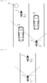
Fig. 3 is a view for explaining an example of a function of the comprehensive assistance system according to the embodiment of the present disclosure. - For example, as illustrated in
Fig. 3 , a case where the mounted straddle-type vehicle 100 travels behind the unmounted straddle-type vehicle 200 is assumed. The surroundingenvironment detector 11 of the rider-assistance system 10 detects position-related information of the unmounted straddle-type vehicle 200 as the target object with respect to a surroundingtravel vehicle 600 as the target object. For example, thetravel vehicle 600 is a vehicle that travels behind the unmounted straddle-type vehicle 200, a vehicle that travels on a side of the unmounted straddle-type vehicle 200, a vehicle that travels in front of the unmounted straddle-type vehicle 200, or the like. In such a case, in the case where it is determined that there is a high possibility of a collision or an approach between the unmounted straddle-type vehicle 200 and thetravel vehicle 600 based on the detection result of the surroundingenvironment detector 11, theexecution section 123 executes the rider-assistance operation to assist with therider 101. Instead of the possibility of the collision or the approach between the unmounted straddle-type vehicle 200 and thetravel vehicle 600, duration of the approach between the unmounted straddle-type vehicle 200 and thetravel vehicle 600 may be determined. Alternatively, instead of the possibility of the collision or the approach between the unmounted straddle-type vehicle 200 and thetravel vehicle 600, a possibility of a collision or an approach between the unmounted straddle-type vehicle 200 and anobstacle 700 may be determined. Examples of theobstacle 700 are a facility on a road (for example, a utility pole, a guardrail, or the like), a stopped vehicle, a pedestrian, an animal, a fallen object, and a defect of a road surface. AlthoughFig. 3 illustrates a case where the mounted straddle-type vehicle 100 travels in a different lane from a lane in which the unmounted straddle-type vehicle 200 travels, the mounted straddle-type vehicle 100 may travel in the same lane as the unmounted straddle-type vehicle 200. For example, theexecution section 123 outputs a control command to cause thenotification device 50 of the unmounted straddle-type vehicle 200 to output a warning so as to notify therider 101 of the collision or the approach. Instead of or in addition to such a warning, the acceleration/deceleration of the unmounted straddle-type vehicle 200 may be controlled so as to avoid the collision or the approach. That is, theexecution section 123 may output the control command to at least one of thebrake system 30 and thedrive system 40 so as to increase the acceleration or reduce the deceleration generated to the unmounted straddle-type vehicle 200. Here, the control of the acceleration/deceleration may be executed automatically in a state where none of the brake operation and the accelerator operation is not performed, or may automatically compensate for shortage of the operation in a state where at least one operation of the brake operation and the accelerator operation is performed. Theexecution section 22 may make the above-described determination, or theexecution section 123 may make the above-described determination. The detection result of thetravel state detector 12 in the rider-assistance system 110 may be taken into consideration for the determination. That is, the detection result of thetravel state detector 12 in the rider-assistance system 110 may be acquired by thecontroller 20 via thecommunication section 23. -
Fig. 4 is a view for explaining an example of the function of the comprehensive assistance system according to the embodiment of the present disclosure. - For example, as illustrated in
Fig. 4 , the case where the mounted straddle-type vehicle 100 travels behind the unmounted straddle-type vehicle 200 is assumed. The surroundingenvironment detector 11 of the rider-assistance system 10 detects the position-related information of the unmounted straddle-type vehicle 200 as the target object with respect to the mounted straddle-type vehicle 100. In such a case, in the case where it is determined that there is a high possibility of the collision or the approach between the mounted straddle-type vehicle 100 and the unmounted straddle-type vehicle 200 based on the detection result of the surroundingenvironment detector 11 and the detection result of thetravel state detector 12 in the rider-assistance system 10, theexecution section 123 executes the rider-assistance operation to assist with therider 101. Instead of the possibility of the collision or the approach between the mounted straddle-type vehicle 100 and the unmounted straddle-type vehicle 200, duration of the approach between the mounted straddle-type vehicle 100 and the unmounted straddle-type vehicle 200 may be determined. AlthoughFig. 4 illustrates a case where the mounted straddle-type vehicle 100 travels in the same lane as the unmounted straddle-type vehicle 200, the mounted straddle-type vehicle 100 may travel in the different lane from the lane in which the unmounted straddle-type vehicle 200 travels. For example, theexecution section 123 outputs the control command to cause thenotification device 50 of the unmounted straddle-type vehicle 200 to output the warning so as to notify therider 101 of the collision or the approach. In addition, theexecution section 22 may output a control command to cause thenotification device 50 of the mounted straddle-type vehicle 100 to output a warning so as to notify therider 1 of the collision or the approach. Instead of or in addition to such a warning, the acceleration/deceleration of at least one of the unmounted straddle-type vehicle 200 and the mounted straddle-type vehicle 100 may be controlled so as to avoid the collision or the approach. That is, theexecution section 123 may output the control command to at least one of thebrake system 30 and thedrive system 40 so as to increase the acceleration or reduce the deceleration generated to the unmounted straddle-type vehicle 200. In addition, theexecution section 22 may output the control command to at least one of thebrake system 30 and thedrive system 40 so as to reduce the acceleration or increase the deceleration generated to the mounted straddle-type vehicle 100. Here, the control of the acceleration/deceleration may be executed automatically in the state where none of the brake operation and the accelerator operation is not performed, or may automatically compensate for the shortage of the operation in the state where at least one operation of the brake operation and the accelerator operation is performed. Theexecution section 22 may make the above-described determination, or theexecution section 123 may make the above-described determination. The detection result of thetravel state detector 12 in the rider-assistance system 110 may be taken into consideration for the determination. That is, the detection result of thetravel state detector 12 in the rider-assistance system 110 may be acquired by thecontroller 20 via thecommunication section 23. -
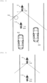
Fig. 5 is a view for explaining an example of the function of the comprehensive assistance system according to the embodiment of the present disclosure. - For example, as illustrated in
Fig. 5 , a case where the mounted straddle-type vehicle 100 travels in front of the unmounted straddle-type vehicle 200 is assumed. That is, the surroundingenvironment detector 11 of the rider-assistance system 10 detects the position-related information of the unmounted straddle-type vehicle 200 as the target object with respect to the surroundingtravel vehicle 600 as the target object. In such a case, in the case where it is determined that there is the high possibility of the collision or the approach between the unmounted straddle-type vehicle 200 and thetravel vehicle 600 based on the detection result of the surroundingenvironment detector 11, theexecution section 123 executes the rider-assistance operation to assist with therider 101. Instead of the possibility of the collision or the approach between the unmounted straddle-type vehicle 200 and thetravel vehicle 600, the duration of the approach between the unmounted straddle-type vehicle 200 and thetravel vehicle 600 may be determined. Alternatively, instead of the possibility of the collision or the approach between the unmounted straddle-type vehicle 200 and thetravel vehicle 600, the possibility of the collision or the approach between the unmounted straddle-type vehicle 200 and theobstacle 700 may be determined. Examples of theobstacle 700 are the facility on the road (for example, the utility pole, the guardrail, or the like), the stopped vehicle, the pedestrian, the animal, the fallen object, and the defect of the road surface. AlthoughFig. 5 illustrates the case where the mounted straddle-type vehicle 100 travels in the same lane as the unmounted straddle-type vehicle 200, the mounted straddle-type vehicle 100 may travel in the different lane from the lane in which the unmounted straddle-type vehicle 200 travels. That is, even when the mounted straddle-type vehicle 100 travels in front of or on a side of the unmounted straddle-type vehicle 200, similar to the case where the mounted straddle-type vehicle 100 travels behind the unmounted straddle-type vehicle 200, the rider-assistance system 110 can execute the rider-assistance operation to assist with therider 101. -
Fig. 6 is a view for explaining an example of the function of the comprehensive assistance system according to the embodiment of the present disclosure. - For example, as illustrated in
Fig. 6 , the case where the mounted straddle-type vehicle 100 travels in front of the unmounted straddle-type vehicle 200 is assumed. That is, the surroundingenvironment detector 11 of the rider-assistance system 10 detects the position-related information of the unmounted straddle-type vehicle 200 as the target object with respect to the mounted straddle-type vehicle 100. In such a case, in the case where it is determined that there is the high possibility of the collision or the approach between the mounted straddle-type vehicle 100 and the unmounted straddle-type vehicle 200 based on the detection result of the surroundingenvironment detector 11 and the detection result of thetravel state detector 12 in the rider-assistance system 10, theexecution section 123 executes the rider-assistance operation to assist with therider 101. Instead of the possibility of the collision or the approach between the mounted straddle-type vehicle 100 and the unmounted straddle-type vehicle 200, the duration of the approach between the mounted straddle-type vehicle 100 and the unmounted straddle-type vehicle 200 may be determined. AlthoughFig. 6 illustrates the case where the mounted straddle-type vehicle 100 travels in the same lane as the unmounted straddle-type vehicle 200, the mounted straddle-type vehicle 100 may travel in the different lane from the lane in which the unmounted straddle-type vehicle 200 travels. That is, even when the mounted straddle-type vehicle 100 travels in front of or on the side of the unmounted straddle-type vehicle 200, similar to the case where the mounted straddle-type vehicle 100 travels behind the unmounted straddle-type vehicle 200, the rider-assistance system 110 can execute the rider-assistance operation to assist with therider 101. - For example, as illustrated in
Fig. 6 , in a situation where the mounted straddle-type vehicle 100 travels in front of the unmounted straddle-type vehicle 200, the rider-assistance system 110 causes the unmounted straddle-type vehicle 200 to execute automatic cruise operation based on the position-related information of the unmounted straddle-type vehicle 200 with respect to the mounted straddle-type vehicle 100, which is acquired by using the surroundingenvironment detector 11. The automatic cruise operation is operation for automatically controlling the acceleration/deceleration of the unmounted straddle-type vehicle 200 without relying on an accelerating/decelerating operation by therider 101. The automatic cruise operation includes cruise control operation and adaptive cruise control operation. In the cruise control operation, the acceleration/deceleration of the unmounted straddle-type vehicle 200 is controlled by thecontroller 120 such that the unmounted straddle-type vehicle 200 travels at a set target speed. Meanwhile, in the adaptive cruise control operation, in addition to such control, an inter-vehicular distance from or collision avoidance performance with a preceding vehicle is maintained. That is, in the adaptive cruise control operation, in the case where the preceding vehicle is not present, the acceleration/deceleration of the unmounted straddle-type vehicle 200 is controlled by thecontroller 120 such that the unmounted straddle-type vehicle 200 travels at the set target speed. On the other hand, in the case where the preceding vehicle is present, the acceleration/deceleration of the unmounted straddle-type vehicle 200 is controlled by thecontroller 120 such that the unmounted straddle-type vehicle 200 travels at a speed that is equal to or lower than the target speed and that aims to maintain the inter-vehicular distance from or the collision avoidance performance with the preceding vehicle. For example, in the case where the mounted straddle-type vehicle 100 executes the cruise control operation, the surroundingenvironment detector 11 of the rider-assistance system 10 detects the position-related information of the unmounted straddle-type vehicle 200 as the target object with respect to the mounted straddle-type vehicle 100. Then, in order to maintain the inter-vehicular distance or the collision avoidance performance between the unmounted straddle-type vehicle 200 and the mounted straddle-type vehicle 100, theexecution section 123 outputs the control command to at least one of thebrake system 30 and thedrive system 40 of the unmounted straddle-type vehicle 200. Consequently, the rider-assistance system 110 executes the cruise control operation of the unmounted straddle-type vehicle 200. Meanwhile, in the case where the mounted straddle-type vehicle 100 does not execute the automatic cruise operation, or in the case where the mounted straddle-type vehicle 100 executes the adaptive cruise control operation based on the surrounding environment information of an area in front of the mounted straddle-type vehicle 100 acquired by using another surroundingenvironment detector 11, the surroundingenvironment detector 11 of the rider-assistance system 10 detects the position-related information of the unmounted straddle-type vehicle 200 as the target object with respect to the mounted straddle-type vehicle 100. Then, in order to maintain the inter-vehicular distance or the collision avoidance performance between the unmounted straddle-type vehicle 200 and the mounted straddle-type vehicle 100, theexecution section 123 outputs the control command to at least one of thebrake system 30 and thedrive system 40 of the unmounted straddle-type vehicle 200. Consequently, the rider-assistance system 110 executes the adaptive cruise control operation of the unmounted straddle-type vehicle 200. In the mounted straddle-type vehicle 100, therider 1 may be able to change at least one of on/off of the adaptive cruise control operation, the target speed, the inter-vehicular distance, and the collision avoidance performance of the unmounted straddle-type vehicle 200. Alternatively, in the unmounted straddle-type vehicle 200, therider 101 may be able to change at least one of those. Both of therider 1 and therider 101 may be able to change at least one of those. In the case where, in the mounted straddle-type vehicle 100, therider 1 can change at least one of the on/off, the target speed, the inter-vehicular distance, and the collision avoidance performance, a permission operation by therider 101 in the unmounted straddle-type vehicle 200 may be set as a change condition. In addition, in the unmounted straddle-type vehicle 200, therider 101 may be able to change at least one of on/off of the cruise control operation, on/off of the adaptive cruise control operation, the target speed, the inter-vehicular distance, and the collision avoidance performance of the mounted straddle-type vehicle 100. In the case where, in the unmounted straddle-type vehicle 200, therider 101 can change at least one of the on/off, the target speed, the inter-vehicular distance, and the collision avoidance performance, a permission operation by therider 1 in the mounted straddle-type vehicle 100 may be set as a change condition. -
Fig. 7 is a view for explaining an example of the function of the comprehensive assistance system according to the embodiment of the present disclosure. - For example, as illustrated in
Fig. 7 , in the situation where the mounted straddle-type vehicle 100 travels in front of the unmounted straddle-type vehicle 200, the rider-assistance system 110 causes the unmounted straddle-type vehicle 200 to execute the automatic cruise operation based on position-related information of a precedingvehicle 800 in front of the mounted straddle-type vehicle 100 with respect to the mounted straddle-type vehicle 100, which is acquired by using the surroundingenvironment detector 11. For example, in the case where the mounted straddle-type vehicle 100 executes the adaptive cruise control operation based on the surrounding environment information of the area in front, which is acquired by using the surroundingenvironment detector 11, theacquisition section 122 acquires the information on the speed of the mounted straddle-type vehicle 100, that is, the information based on the surrounding environment information of the mounted straddle-type vehicle 100 via thecommunication section 121. Then, in order to make the speed of the unmounted straddle-type vehicle 200 and the speed of the mounted straddle-type vehicle 100 match each other, theexecution section 123 outputs the control command to at least one of thebrake system 30 and thedrive system 40 of the unmounted straddle-type vehicle 200. Consequently, the rider-assistance system 110 executes the adaptive cruise control operation of the unmounted straddle-type vehicle 200. At the time, the information on the positions of the mounted straddle-type vehicle 100 and the unmounted straddle-type vehicle 200 may be acquired based on the detection results of thetravel state detectors 12, so as to maintain the inter-vehicular distance or the collision avoidance performance between the unmounted straddle-type vehicle 200 and the mounted straddle-type vehicle 100. In the mounted straddle-type vehicle 100, therider 1 may be able to change at least one of the on/off of the adaptive cruise control operation, the inter-vehicular distance, and the collision avoidance performance of the unmounted straddle-type vehicle 200. Alternatively, in the unmounted straddle-type vehicle 200, therider 101 may be able to change at least one of those. Both of therider 1 and therider 101 may be able to change at least one of those. In the case where, in the mounted straddle-type vehicle 100, therider 1 can change at least one of the on/off, the inter-vehicular distance, and the collision avoidance performance, the permission operation by therider 101 in the unmounted straddle-type vehicle 200 may be set as the change condition. In addition, in the unmounted straddle-type vehicle 200, therider 101 may be able to change at least one of the on/off of the adaptive cruise control operation, the target speed, the inter-vehicular distance, and the collision avoidance performance of the mounted straddle-type vehicle 100. In the case where, in the unmounted straddle-type vehicle 200, therider 101 can change at least one of the on/off, the target speed, the inter-vehicular distance, and the collision avoidance performance, the permission operation by therider 1 in the mounted straddle-type vehicle 100 may be set as the change condition. Here, when theexecution section 123 causes the unmounted straddle-type vehicle 200 to execute the adaptive cruise control operation based on the position-related information of the precedingvehicle 800 with respect to the mounted straddle-type vehicle 100, the position-related information of the unmounted straddle-type vehicle 200 as the target object with respect to the mounted straddle-type vehicle 100, which is acquired by using the othersurrounding environment detector 11 of the rider-assistance system 10, may be taken into consideration. In addition, in the case where the mounted straddle-type vehicle 100 executes the cruise control operation, theacquisition section 122 may acquire the information on the speed of the mounted straddle-type vehicle 100 via thecommunication section 121, and theexecution section 123 may thereby cause the rider-assistance system 110 to execute the cruise control operation. In the mounted straddle-type vehicle 100, therider 1 may be able to change the on/off of the cruise control operation of the unmounted straddle-type vehicle 200. Alternatively, in the unmounted straddle-type vehicle 200, therider 101 may be able to change such on/off. Both of therider 1 and therider 101 may be able to change such on/off. In the case where, in the mounted straddle-type vehicle 100, therider 1 can change the on/off, the permission operation by therider 101 in the unmounted straddle-type vehicle 200 may be set as the change condition. In addition, in the unmounted straddle-type vehicle 200, therider 101 may be able to change the on/off of the cruise control operation of the mounted straddle-type vehicle 100. In the case where, in the unmounted straddle-type vehicle 200, therider 101 can change the on/off, the permission operation by therider 1 in the mounted straddle-type vehicle 100 may be set as the change condition. - A description will be made on operation of the comprehensive assistance system according to the embodiment.
-
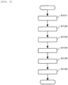
Fig. 8 is a chart for explaining an example of the operation of the comprehensive assistance system according to the embodiment of the present disclosure. An order of steps may appropriately be switched, any of the steps may appropriately be omitted, or an another step may appropriately be added. - The
comprehensive assistance system 500 executes the operation illustrated inFig. 8 during the travel of the mounted straddle-type vehicle 100 and the unmounted straddle-type vehicle 200. - In step S101, the
acquisition section 21 in thecontroller 20 of the rider-assistance system 10 acquires the surrounding environment information based on the output from the surroundingenvironment detector 11, and acquires the travel state information of the mounted straddle-type vehicle 100 based on the output from thetravel state detector 12 of the mounted straddle-type vehicle 100. - Next, in step S102, the
execution section 22 in thecontroller 20 of the rider-assistance system 10 outputs the signal to each of the various devices in the rider-assistance system 10 based on the various types of the information acquired in step S101, and executes the rider-assistance operation to assist with therider 1 of the mounted straddle-type vehicle 100. - Next, in step S103, the
communication section 23 in thecontroller 20 of the rider-assistance system 10 transmits, to the rider-assistance system 110 assisting therider 101 in driving the unmounted straddle-type vehicle 200, the information based on the surrounding environment information of the mounted straddle-type vehicle 100 by the wireless communication, and such information is used to execute the rider-assistance operation that assists with therider 101. - Next, in step S104, the
communication section 121 in thecontroller 120 of the rider-assistance system 110 receives, from the rider-assistance system 10 assisting therider 1 in driving the mounted straddle-type vehicle 100, the information based on the surrounding environment information of the mounted straddle-type vehicle 100 by the wireless communication. - Next, in step S105, the
acquisition section 122 in thecontroller 120 of the rider-assistance system 110 acquires the information, which is based on the surrounding environment information of the mounted straddle-type vehicle 100, based on the output from thecommunication section 121, and acquires the travel state information of the unmounted straddle-type vehicle 200 based on the output from thetravel state detector 12 of the unmounted straddle-type vehicle 200. - Next, in step S106, the
execution section 123 in thecontroller 120 of the rider-assistance system 110 outputs the signal to each of the various devices in the rider-assistance system 110 based on the various types of the information acquired in step S105, and executes the rider-assistance operation to assist with therider 101 of the unmounted straddle-type vehicle 200. - A description will be made on effects of the comprehensive assistance system according to the embodiment.
- In the
comprehensive assistance system 500, the information based on the surrounding environment information of the mounted straddle-type vehicle 100 is transmitted from the rider-assistance system 10, which assists therider 1 in driving the mounted straddle-type vehicle 100, to thecontroller 120 of the rider-assistance system 110, which assists therider 101 in driving the unmounted straddle-type vehicle 200. Thus, it is possible to assist therider 101 in driving the unmounted straddle-type vehicle 200. - Preferably, only in the case where the mounted straddle-
type vehicle 100 is the vehicle that is set in the unmounted straddle-type vehicle 200 as the vehicle traveling in the same group, and/or only in the case where the unmounted straddle-type vehicle 200 is the vehicle that is set in the mounted straddle-type vehicle 100 as the vehicle traveling in the same group, the rider-assistance system 110 may execute the rider-assistance operation using the information based on the surrounding environment information of the mounted straddle-type vehicle 100. With such a configuration, therider 101 can be assisted appropriately in driving the unmounted straddle-type vehicle 200. - The embodiment of the present disclosure is not limited to that in the above description. That is, the present disclosure includes modes in each of which the embodiment that has been described so far is modified. In addition, the present disclosure includes a mode in which the embodiment that has been described so far is only partially implemented or a mode in which the modes are combined.
-
- 1, 101: Rider
- 10, 110: Rider-assistance system
- 11: Surrounding environment detector
- 12: Travel state detector
- 20, 120: Controller
- 21, 122: Acquisition section
- 22, 123: Execution section
- 23, 121: Communication section
- 30: Brake system
- 40: Drive system
- 50: Notification device
- 100, 200: Straddle-type vehicle
- 500: Comprehensive assistance system
- 600: Travel vehicle
- 700: Obstacle
- 800: Preceding vehicle
Claims (12)
- A controller (120) for a first rider-assistance system (110) of a first straddle-type vehicle (200), the first rider-assistance system (110) configured to assist a first rider (101) in driving the first straddle-type vehicle (200), the controller (120) comprising:an execution section (123) that is configured to cause the first rider-assistance system (110) to execute a rider-assistance operation for assisting the first rider (101); anda communication section (121) that is configured to receive information from a second rider-assistance system (10) of a second straddle-type vehicle (100) directly or indirectly by wireless communication, the information being based on surrounding environment information of the second straddle-type vehicle (100), the second straddle-type vehicle (100) having the second rider-assistance system (10) that is configured to assist a second rider (1) in driving the second straddle-type vehicle (100) and a surrounding environment detector (11) that is configured to detect a position-related information of a surrounding target object near the second straddle-type vehicle (100), whereinthe execution section (123) causes the first rider-assistance system (110) to execute the rider-assistance operation in response to the information received by the communication section (121),characterized in thatthe second straddle-type vehicle (100) is a vehicle that is traveling behind or in front of the first straddle-type vehicle (200) in a group, andthe target object is a third traveling vehicle (600) near to the first straddle-type vehicle (200) and the second straddle-type vehicle (100) or the first straddle-type vehicle (200).
- The controller (120) according to claim 1, wherein
the rider-assistance operation outputs a warning to the first rider (101) in response to the information received by the communication section (121). - The controller (120) according to claim 2, wherein
the warning warns the first straddle-type vehicle (200) that the first straddle-type vehicle (200) possibly collides with the third vehicle (600) traveling near the first straddle-type vehicle (200) or that the first straddle-type vehicle (200) is approaching the third vehicle (600) traveling near the first straddle-type vehicle (200). - The controller (120) according to any one of claims 2 to 3, wherein
the warning warns the first straddle-type vehicle (200) that the first straddle-type vehicle (200) possibly collides with the second straddle-type vehicle (200) or that the first straddle-type vehicle (200) is approaching the second straddle-type vehicle (100). - The controller (120) according to any one of claims 1 to 4, wherein
the rider-assistance operation automatically controls a brake system (30) of the first straddle-type vehicle (200) in response to the information received by the communication section (121). - The controller (120) according to any one of claims 1 to 5, wherein
the rider-assistance operation automatically controls a drive system (40) of the first straddle-type vehicle (200) in response to the information received by the communication section (121). - The controller (120) according to any one of claims 1 to 6, wherein
the rider-assistance operation causes the first straddle-type vehicle (200) to execute an automatic cruise operation in response to the information received by the communication section (121). - The controller (120) according to claim 7, wherein
in the automatic cruise operation, acceleration/deceleration of the first straddle-type vehicle (200) is controlled based on relative position-related information between the second straddle-type vehicle (100) and the first straddle-type vehicle (200). - The controller (120) according to claim 7 or 8, whereinthe automatic cruise operation is adaptive cruise control operation, andin the adaptive cruise control operation, the acceleration/deceleration of the first straddle-type vehicle (200) is controlled based on relative position-related information between the second straddle-type vehicle (100) and a preceding vehicle (800) of the second straddle-type vehicle (100).
- A controller (20) for a second rider-assistance system (10) of a second straddle-type vehicle (100) that has a surrounding environment detector (11) configured to detect position-related information of a target object in surroundings, the second rider-assistance system (10) configured to assist a second rider (1) in driving the second straddle-type vehicle (100), the controller (20) comprising:
an acquisition section (21) that is configured to acquire surrounding environment information of the second straddle-type vehicle (100) based on output of the surrounding environment detector (11), and further comprising:a communication section (23) that is configured to transmit information, directly or indirectly by wireless communication, to a first rider-assistance system (110) of a first straddle-type vehicle (200) having no surrounding environment detector configured to detect position-related information of a target object in the surroundings, the information being based on the surrounding environment information of the second straddle-type vehicle (100) and being to be used to execute a rider-assistance operation assisting a first rider (101) in driving the first straddle-type vehicle (200),characterized in thatthe first straddle-type vehicle (200) is a vehicle that is traveling behind or in front of the second straddle-type vehicle (100) in a group, andthe target object is a third traveling vehicle (600) near to the first straddle-type vehicle (200) and the second straddle-type vehicle (100) or the first straddle-type vehicle (200). - A control method for a first rider-assistance system (110) of a first straddle-type vehicle (200), the first rider-assistance system (110) configured to assist a first rider (101) in driving the first straddle-type vehicle (200), the control method comprising:executing (S106) a rider-assistance operation that assists the first rider (101) in a manner that an execution section (123) of a controller (120) causes the first rider-assistance system (110) to execute the rider-assistance operation; andreceiving (S104) information from a second rider-assistance system (10) of the second straddle-type vehicle (100) in a manner that a communication section (121) of the controller (120) receives the information from the second rider-assistance system (10) directly or indirectly by wireless communication, the information being based on surrounding environment information of the second straddle-type vehicle (100), the second straddle-type vehicle (100) that has a surrounding environment detector (11) configured to detect a position-related information of a target object in the surroundings, the second rider-assistance system (10) configured to assists a second rider (1) in driving the second straddle-type vehicle (100),wherein the execution section (123) causes the first rider-assistance system (110) to execute the rider-assistance operation based on the information received by the communication section (121),characterized in thatthe second straddle-type vehicle (100) is a vehicle that is traveling behind or in front of the first straddle-type vehicle (200) in a group, andthe target object is a third traveling vehicle (600) near to the first straddle-type vehicle (200) and the second straddle-type vehicle (100) or the first straddle-type vehicle (200).
- A control method for a second rider-assistance system (10) of a second straddle-type vehicle (100) having a surrounding environment detector (11) that is configured to detect position-related information of a target object in surroundings, the second rider-assistance system (10) configured to assist a second rider (1) in driving the second straddle-type vehicle (100), the control method comprising:acquiring (S101), by using an acquisition section (21) of a controller (20), a surrounding environment information of the second straddle-type vehicle (100) in response to an output from the surrounding environment detector (11); andtransmitting (S103) information to a first rider-assistance system (110) of a first straddle-type vehicle (200) in a manner that a communication section (23) of the controller (20) transmits the information to the first rider-assistance system (110) directly or indirectly via wireless communication, the information being based on the surrounding environment information of the second straddle-type vehicle (100) and being to be used to execute, by the first rider-assistance system (110), a rider-assistance operation assisting a first rider (101) in driving the first straddle-type vehicle (200), the first straddle-type vehicle (200) having no surrounding environment detector that is configured to detect position-related information of a target object in the surroundings,characterized in thatthe first straddle-type vehicle (200) is a vehicle that is traveling behind or in front of the second straddle-type vehicle (100) in a group, andthe target object is a third traveling vehicle (600) near to the first straddle-type vehicle (200) and the second straddle-type vehicle (100) or the first straddle-type vehicle (200).
Applications Claiming Priority (3)
| Application Number | Priority Date | Filing Date | Title |
|---|---|---|---|
| JP2020214074A JP2022099973A (en) | 2020-12-23 | 2020-12-23 | Control device and control method of rider support system |
| PCT/IB2021/060298 WO2022136963A1 (en) | 2020-12-23 | 2021-11-08 | Control device and control method for rider assistance system |
| EP21819204.5A EP4269203B1 (en) | 2020-12-23 | 2021-11-08 | Control device and control method for rider assistance system |
Related Parent Applications (2)
| Application Number | Title | Priority Date | Filing Date |
|---|---|---|---|
| EP21819204.5A Division EP4269203B1 (en) | 2020-12-23 | 2021-11-08 | Control device and control method for rider assistance system |
| EP21819204.5A Division-Into EP4269203B1 (en) | 2020-12-23 | 2021-11-08 | Control device and control method for rider assistance system |
Publications (2)
| Publication Number | Publication Date |
|---|---|
| EP4397552A2 true EP4397552A2 (en) | 2024-07-10 |
| EP4397552A3 EP4397552A3 (en) | 2024-08-21 |
Family
ID=78820744
Family Applications (3)
| Application Number | Title | Priority Date | Filing Date |
|---|---|---|---|
| EP24155514.3A Pending EP4397552A3 (en) | 2020-12-23 | 2021-11-08 | Control device and control method for rider assistance system |
| EP24155513.5A Pending EP4397551A3 (en) | 2020-12-23 | 2021-11-08 | Control device and control method for rider assistance system |
| EP21819204.5A Active EP4269203B1 (en) | 2020-12-23 | 2021-11-08 | Control device and control method for rider assistance system |
Family Applications After (2)
| Application Number | Title | Priority Date | Filing Date |
|---|---|---|---|
| EP24155513.5A Pending EP4397551A3 (en) | 2020-12-23 | 2021-11-08 | Control device and control method for rider assistance system |
| EP21819204.5A Active EP4269203B1 (en) | 2020-12-23 | 2021-11-08 | Control device and control method for rider assistance system |
Country Status (4)
| Country | Link |
|---|---|
| US (1) | US20240116508A1 (en) |
| EP (3) | EP4397552A3 (en) |
| JP (2) | JP2022099973A (en) |
| WO (1) | WO2022136963A1 (en) |
Families Citing this family (1)
| Publication number | Priority date | Publication date | Assignee | Title |
|---|---|---|---|---|
| JP2024166036A (en) * | 2023-05-17 | 2024-11-28 | トヨタ自動車株式会社 | Calculation device |
Family Cites Families (41)
| Publication number | Priority date | Publication date | Assignee | Title |
|---|---|---|---|---|
| US7720580B2 (en) * | 2004-12-23 | 2010-05-18 | Donnelly Corporation | Object detection system for vehicle |
| US20110276216A1 (en) * | 2010-05-07 | 2011-11-10 | Texas Instruments Incorporated | Automotive cruise controls, circuits, systems and processes |
| JP2013007632A (en) * | 2011-06-23 | 2013-01-10 | Yupiteru Corp | Tooling auxiliary system and tooling auxiliary device |
| US10474166B2 (en) * | 2011-07-06 | 2019-11-12 | Peloton Technology, Inc. | System and method for implementing pre-cognition braking and/or avoiding or mitigation risks among platooning vehicles |
| WO2013148675A1 (en) * | 2012-03-26 | 2013-10-03 | Robert Bosch Gmbh | Multi-surface model-based tracking |
| US10417914B1 (en) * | 2014-05-30 | 2019-09-17 | State Farm Mutual Automobile Insurance Company | Systems and methods for determining a vehicle is at an elevated risk for an animal collision |
| JP2015228092A (en) * | 2014-05-30 | 2015-12-17 | 株式会社デンソー | Drive assist system and drive assist program |
| US10112609B2 (en) * | 2014-06-10 | 2018-10-30 | Denso Corporation | Collision avoidance apparatus |
| US10510256B2 (en) * | 2014-10-20 | 2019-12-17 | Robert Brandriff | Vehicle collision avoidance system and method |
| JP2016146041A (en) * | 2015-02-06 | 2016-08-12 | 住友電気工業株式会社 | Follow-up movement support system, mobile communication device, and control program |
| US9759574B2 (en) * | 2015-07-14 | 2017-09-12 | Ford Global Technologes, Llc | Vehicle emergency broadcast and relay |
| EP3335954A4 (en) * | 2015-08-17 | 2018-09-12 | Yamaha Hatsudoki Kabushiki Kaisha | Leaning vehicle |
| DE102015220902A1 (en) * | 2015-10-27 | 2017-04-27 | Robert Bosch Gmbh | Method for increasing the driving safety of a vehicle |
| JP6211043B2 (en) * | 2015-11-05 | 2017-10-11 | 三菱電機株式会社 | Vehicle collision prevention device |
| JP6477453B2 (en) * | 2015-12-17 | 2019-03-06 | 株式会社デンソー | Object detection device and object detection method |
| JP2017138887A (en) * | 2016-02-05 | 2017-08-10 | スズキ株式会社 | Automatic driving continuation propriety determination device in merging with lane, and method for determining automatic driving continuation propriety |
| US10332403B2 (en) * | 2017-01-04 | 2019-06-25 | Honda Motor Co., Ltd. | System and method for vehicle congestion estimation |
| US11276256B2 (en) * | 2016-08-25 | 2022-03-15 | Airbnb, Inc. | Traffic event recording and recreation |
| US10171953B2 (en) * | 2016-12-15 | 2019-01-01 | At&T Mobility Ii Llc | Vehicle event notification via cell broadcast |
| CN108282512B (en) * | 2017-01-04 | 2022-06-24 | 本田技研工业株式会社 | System and method for vehicle control using vehicle communication |
| IT201700050502A1 (en) * | 2017-05-10 | 2018-11-10 | Ducati Motor Holding Spa | MOTORCYCLE WITH A DETECTION DEVICE FOR A VEHICLE THAT OVERALLS FROM THE BACK |
| US10766489B2 (en) * | 2017-09-05 | 2020-09-08 | Arizona Board Of Regents On Behalf Of Arizona State University | Model predictive adaptive cruise control for reducing rear-end collision risk with follower vehicles |
| CA3079092A1 (en) * | 2017-11-02 | 2019-05-09 | Damon Motors Inc. | Anticipatory motorcycle safety system |
| EP3680137B1 (en) * | 2017-12-28 | 2021-09-01 | Honda Motor Co., Ltd. | Brake device for saddle-type vehicles |
| US20190208449A1 (en) * | 2017-12-29 | 2019-07-04 | Industrial Technology Research Institute | Mobile edge platform servers and device and message management methods of v2x service thereof |
| US11237555B1 (en) * | 2018-03-09 | 2022-02-01 | State Farm Mutual Automobile Insurance Company | Backup control systems and methods for autonomous vehicles |
| WO2020041188A1 (en) * | 2018-08-20 | 2020-02-27 | Indian Motorcycle International, LLC | Wheeled vehicle adaptive speed control method and system |
| US11866042B2 (en) * | 2018-08-20 | 2024-01-09 | Indian Motorcycle International, LLC | Wheeled vehicle adaptive speed control method and system |
| JP2020050220A (en) * | 2018-09-28 | 2020-04-02 | ロベルト・ボッシュ・ゲゼルシャフト・ミト・ベシュレンクテル・ハフツングRobert Bosch Gmbh | Control device and control method |
| DE102018219027A1 (en) * | 2018-11-08 | 2020-05-14 | Robert Bosch Gmbh | Method and device for the driver-independent temporary deactivation of a constant speed function for a single-track motor vehicle |
| US20200201356A1 (en) * | 2018-12-21 | 2020-06-25 | Peloton Technology, Inc. | Systems and methods for managing platooning behavior |
| US11505181B2 (en) * | 2019-01-04 | 2022-11-22 | Toyota Motor Engineering & Manufacturing North America, Inc. | System, method, and computer-readable storage medium for vehicle collision avoidance on the highway |
| CN113631470B (en) * | 2019-03-29 | 2023-02-03 | 本田技研工业株式会社 | Driving support device for saddle-ride type vehicle |
| KR102228881B1 (en) * | 2019-08-19 | 2021-03-18 | 엘지전자 주식회사 | Method and apparatus for receiving of driving data in platooning in autonomous driving system |
| KR20190104474A (en) * | 2019-08-20 | 2019-09-10 | 엘지전자 주식회사 | Apparatus and method for controlling the driving of a vehicle |
| JP7291231B2 (en) * | 2019-09-27 | 2023-06-14 | 本田技研工業株式会社 | Body posture detection device and saddle type vehicle |
| US20220383750A1 (en) * | 2020-01-06 | 2022-12-01 | Intel Corporation | Intelligent transport system vulnerable road user clustering, user profiles, and maneuver coordination mechanisms |
| US11708071B2 (en) * | 2020-03-30 | 2023-07-25 | Denso Corporation | Target-orientated navigation system for a vehicle using a generic navigation system and related method |
| US12187289B1 (en) * | 2020-04-07 | 2025-01-07 | State Farm Mutual Automobile Insurance Company | Systems and methods for generating refined risk models responsive to vehicle-based telematics data |
| US12122365B2 (en) * | 2020-07-01 | 2024-10-22 | The Regents Of The University Of Michigan | Contingent model predictive control incorporating online estimation of nominal and uncertain parameters |
| US11249195B1 (en) * | 2020-11-29 | 2022-02-15 | Kiomars Anvari | Exchange of time of day between two IoT devices |
-
2020
- 2020-12-23 JP JP2020214074A patent/JP2022099973A/en active Pending
-
2021
- 2021-11-08 WO PCT/IB2021/060298 patent/WO2022136963A1/en not_active Ceased
- 2021-11-08 EP EP24155514.3A patent/EP4397552A3/en active Pending
- 2021-11-08 EP EP24155513.5A patent/EP4397551A3/en active Pending
- 2021-11-08 EP EP21819204.5A patent/EP4269203B1/en active Active
- 2021-11-08 JP JP2022570754A patent/JP7553604B2/en active Active
- 2021-11-08 US US18/257,648 patent/US20240116508A1/en not_active Abandoned
Also Published As
| Publication number | Publication date |
|---|---|
| JP2022099973A (en) | 2022-07-05 |
| JPWO2022136963A1 (en) | 2022-06-30 |
| JP7553604B2 (en) | 2024-09-18 |
| US20240116508A1 (en) | 2024-04-11 |
| EP4269203A1 (en) | 2023-11-01 |
| EP4397551A2 (en) | 2024-07-10 |
| EP4269203B1 (en) | 2026-03-18 |
| EP4397552A3 (en) | 2024-08-21 |
| EP4397551A3 (en) | 2024-08-21 |
| WO2022136963A1 (en) | 2022-06-30 |
Similar Documents
| Publication | Publication Date | Title |
|---|---|---|
| JP6460008B2 (en) | Automatic driving device | |
| EP3950449B1 (en) | Control device for controlling operation of motorcycle, and control method | |
| EP4068242B1 (en) | Processor and processing method for rider-assistance system of straddle-type vehicle, rider-assistance system of straddle-type vehicle, and straddle-type vehicle | |
| EP3893218A1 (en) | Processing apparatus and processing method for saddle-type vehicle rider assistance system, saddle-type vehicle rider assistance system, and saddle-type vehicle | |
| EP4269203B1 (en) | Control device and control method for rider assistance system | |
| US12358504B2 (en) | Controller and control method for controlling operation of motorcycle | |
| EP4447019A1 (en) | Assistance system and control method thereof | |
| EP4234355B1 (en) | Control device and control method | |
| EP4737244A1 (en) | Control device and control method for rider assist system | |
| JP7561211B2 (en) | Control device and control method for controlling the operation of a motorcycle | |
| EP4549273A1 (en) | Control device and control method for motorcyclist assistance system | |
| EP4275976B1 (en) | Control device and control method | |
| WO2025233705A1 (en) | Control device for leaning vehicle and control method for leaning vehicle |
Legal Events
| Date | Code | Title | Description |
|---|---|---|---|
| PUAI | Public reference made under article 153(3) epc to a published international application that has entered the european phase |
Free format text: ORIGINAL CODE: 0009012 |
|
| STAA | Information on the status of an ep patent application or granted ep patent |
Free format text: STATUS: THE APPLICATION HAS BEEN PUBLISHED |
|
| AC | Divisional application: reference to earlier application |
Ref document number: 4269203 Country of ref document: EP Kind code of ref document: P |
|
| AK | Designated contracting states |
Kind code of ref document: A2 Designated state(s): AL AT BE BG CH CY CZ DE DK EE ES FI FR GB GR HR HU IE IS IT LI LT LU LV MC MK MT NL NO PL PT RO RS SE SI SK SM TR |
|
| REG | Reference to a national code |
Ref country code: DE Ref legal event code: R079 Free format text: PREVIOUS MAIN CLASS: B60W0010060000 Ipc: B60W0030165000 |
|
| PUAL | Search report despatched |
Free format text: ORIGINAL CODE: 0009013 |
|
| AK | Designated contracting states |
Kind code of ref document: A3 Designated state(s): AL AT BE BG CH CY CZ DE DK EE ES FI FR GB GR HR HU IE IS IT LI LT LU LV MC MK MT NL NO PL PT RO RS SE SI SK SM TR |
|
| RIC1 | Information provided on ipc code assigned before grant |
Ipc: B60W 10/06 20060101ALI20240717BHEP Ipc: B60W 50/14 20200101ALI20240717BHEP Ipc: H04W 4/46 20180101ALI20240717BHEP Ipc: B60W 30/18 20120101ALI20240717BHEP Ipc: B60W 30/09 20120101ALI20240717BHEP Ipc: B60W 10/184 20120101ALI20240717BHEP Ipc: B60W 30/165 20200101AFI20240717BHEP |
|
| STAA | Information on the status of an ep patent application or granted ep patent |
Free format text: STATUS: REQUEST FOR EXAMINATION WAS MADE |
|
| 17P | Request for examination filed |
Effective date: 20250221 |