EP4397535A1 - Seat rotation adjustment structure and child safety seat - Google Patents
Seat rotation adjustment structure and child safety seat Download PDFInfo
- Publication number
- EP4397535A1 EP4397535A1 EP22862829.3A EP22862829A EP4397535A1 EP 4397535 A1 EP4397535 A1 EP 4397535A1 EP 22862829 A EP22862829 A EP 22862829A EP 4397535 A1 EP4397535 A1 EP 4397535A1
- Authority
- EP
- European Patent Office
- Prior art keywords
- positioning plate
- handle body
- base
- positioning
- adjustment structure
- Prior art date
- Legal status (The legal status is an assumption and is not a legal conclusion. Google has not performed a legal analysis and makes no representation as to the accuracy of the status listed.)
- Granted
Links
Images






Classifications
-
- B—PERFORMING OPERATIONS; TRANSPORTING
- B60—VEHICLES IN GENERAL
- B60N—SEATS SPECIALLY ADAPTED FOR VEHICLES; VEHICLE PASSENGER ACCOMMODATION NOT OTHERWISE PROVIDED FOR
- B60N2/00—Seats specially adapted for vehicles; Arrangement or mounting of seats in vehicles
- B60N2/24—Seats specially adapted for vehicles; Arrangement or mounting of seats in vehicles for particular purposes or particular vehicles
- B60N2/26—Seats specially adapted for vehicles; Arrangement or mounting of seats in vehicles for particular purposes or particular vehicles for children
- B60N2/28—Seats readily mountable on, and dismountable from, existing seats or other parts of the vehicle
-
- B—PERFORMING OPERATIONS; TRANSPORTING
- B60—VEHICLES IN GENERAL
- B60N—SEATS SPECIALLY ADAPTED FOR VEHICLES; VEHICLE PASSENGER ACCOMMODATION NOT OTHERWISE PROVIDED FOR
- B60N2/00—Seats specially adapted for vehicles; Arrangement or mounting of seats in vehicles
- B60N2/24—Seats specially adapted for vehicles; Arrangement or mounting of seats in vehicles for particular purposes or particular vehicles
- B60N2/26—Seats specially adapted for vehicles; Arrangement or mounting of seats in vehicles for particular purposes or particular vehicles for children
- B60N2/28—Seats readily mountable on, and dismountable from, existing seats or other parts of the vehicle
- B60N2/2869—Seats readily mountable on, and dismountable from, existing seats or other parts of the vehicle rotatable about a vertical axis
-
- B—PERFORMING OPERATIONS; TRANSPORTING
- B60—VEHICLES IN GENERAL
- B60N—SEATS SPECIALLY ADAPTED FOR VEHICLES; VEHICLE PASSENGER ACCOMMODATION NOT OTHERWISE PROVIDED FOR
- B60N2205/00—General mechanical or structural details
- B60N2205/20—Measures for elimination or compensation of play or backlash
Definitions
- the present disclosure relates to the technical field of child safety seats, and particularly to a seat rotation adjustment structure, and a child safety seat including the same.
- Child safety seats specially designed for children can effectively restrain children and greatly improve the safety of children during driving.
- child safety seats are designed as rotatable structures in the prior art, so that the child safety seats can be rotated 90° or 180°.
- most of the existing seat rotation locking structures for child safety seats involve a complicated structure, high manufacturing costs, and inconvenient rotation operations.
- a recessed groove configured for mounting the positioning plate is provided on the handle body, and an upper end and a lower end of the first reset member are respectively pressed against the positioning plate and a bottom of the recessed groove.
- the release handle assembly further includes a rotating shaft, and the positioning plate is hingedly connected to the handle body through the rotating shaft.
- the protruding column is connected to a fastener configured for limiting a vertical movement of the handle body.
- a second reset member configured for pushing the handle body to move backward is arranged between the handle body and the base.
- a brim is arranged on a peripheral wall of the rotary disc, and the accommodating space is formed between the brim and the base.
- a distance between the brim and the base gradually decreases from a rear end to a front end.
- the child safety seat of the present disclosure has the same advantages as those of the seat rotation adjustment structure compared with the prior art, so no more details will be described herein.
- orientation or position relationships indicated by the terms such as “up” and “down” are orientation or position relationships based on the normal use of the product.
- a top of the positioning plate 32 is pressed against the rotary disc 2 all the time.
- a user pulls the handle body 31 to drive the positioning plate 32 to move forward.
- the positioning plate 32 is disengaged from the positioning groove 21, and the top of the positioning plate 32 receives a downward pressure, so that the rear end of the positioning plate 32 rotates downward about the front end of the positioning plate 32.
- the first reset member 33 is compressed by a pressure from the positioning plate 32.
- the handle body 31 moves backward toward an original position and drives the positioning plate 32 to move backward, and the rear end of the positioning plate 32 rotates upward about the front end of the positioning plate 32 under an elastic restoring force of the first reset member 33 to enter the positioning groove 21, and is locked to the positioning groove 21.
- a seat position switching operation is completed.
- a sliding groove 312 is provided on the handle body 31, and a protruding column 11 configured for engaging with the sliding groove 312 is arranged on the base 1.
- the length direction of the sliding groove 312 is consistent with the front-rear direction.
- the protruding column 11 is arranged to be perpendicular to the front-rear direction.
- the positioning plate 32 is locked to a positioning groove 21 of the positioning grooves 21.
- the protruding column 11 is pressed against a front end of the sliding groove 312.
- the protruding column 11 is pressed against a rear end of the sliding groove 312.
- a brim 22 is arranged on a peripheral wall of the rotary disc 2, and the accommodating space 4 is formed between the brim 22 and the base 1.
- the release handle assembly 3 is arranged on the base 1, the plurality of positioning grooves 21 configured for engaging with the positioning plate 32 of the release handle assembly 3 are arranged on the rotary disc 2, and through the movement of the handle body 31 and the restriction of the movement of the positioning plate 32 by the accommodating space 4, the positioning plate 32 can be locked to or disengaged from a positioning groove 21 of the positioning grooves 21, so that the position of the rotary disc 2 can be changed to achieve seat rotation and locking.
- Such a design involves a simple structure, a small number of parts, and low improvement costs, and is suitable for use in a wide range of applications for improvement.
- rotation and locking operations are convenient and stable, so that high operation efficiency is achieved, thereby improving user experience.
Landscapes
- Engineering & Computer Science (AREA)
- Health & Medical Sciences (AREA)
- Child & Adolescent Psychology (AREA)
- General Health & Medical Sciences (AREA)
- Aviation & Aerospace Engineering (AREA)
- Transportation (AREA)
- Mechanical Engineering (AREA)
- Seats For Vehicles (AREA)
Abstract
Description
- The present disclosure relates to the technical field of child safety seats, and particularly to a seat rotation adjustment structure, and a child safety seat including the same.
- With the improvement of people's awareness of driving safety, more attention is being paid to the safety of children during driving. Child safety seats specially designed for children can effectively restrain children and greatly improve the safety of children during driving. In order to adapt to children of more ages, child safety seats are designed as rotatable structures in the prior art, so that the child safety seats can be rotated 90° or 180°. However, most of the existing seat rotation locking structures for child safety seats involve a complicated structure, high manufacturing costs, and inconvenient rotation operations.
- To solve at least one of the above problems, the present disclosure first provides a seat rotation adjustment structure, including a base and a rotary disc rotatably connected to the base, where a release handle assembly is mounted on the base; the release handle assembly includes a handle body, a positioning plate, and a first reset member; the handle body is connected to the base in a forward and backward movable manner; a front end of the positioning plate is hingedly connected to the handle body, and a rear end of the positioning plate is connected to the first reset member; an accommodating space configured for restricting a movement of the positioning plate is formed between the rotary disc and the base; a plurality of positioning grooves configured for engaging with the positioning plate are provided on the rotary disc; when the positioning plate is aligned with a positioning groove of the positioning grooves, the positioning plate is pushed by the handle body and the first reset member to lock to the positioning groove; and after the handle body is pulled forward to allow the positioning plate to disengage from the positioning groove, the positioning plate completely enters the accommodating space, to achieve a rotation of the rotary disc relative to the base.
- Optionally, a recessed groove configured for mounting the positioning plate is provided on the handle body, and an upper end and a lower end of the first reset member are respectively pressed against the positioning plate and a bottom of the recessed groove.
- Optionally, the release handle assembly further includes a rotating shaft, and the positioning plate is hingedly connected to the handle body through the rotating shaft.
- Optionally, a sliding groove is provided on the handle body, and a protruding column configured for engaging with the sliding groove is arranged on the base.
- Optionally, the protruding column is connected to a fastener configured for limiting a vertical movement of the handle body.
- Optionally, a second reset member configured for pushing the handle body to move backward is arranged between the handle body and the base.
- Optionally, a handle groove is provided at a rear end of the handle body, and a window configured for exposing the handle groove is provided on the base.
- Optionally, a brim is arranged on a peripheral wall of the rotary disc, and the accommodating space is formed between the brim and the base.
- Optionally, a distance between the brim and the base gradually decreases from a rear end to a front end.
- Compared with the prior art, in the seat rotation adjustment structure of the present disclosure, the release handle assembly is arranged on the base, the plurality of positioning grooves configured for engaging with the positioning plate of the release handle assembly are arranged on the rotary disc, and through the movement of the handle body and the restriction of the movement of the positioning plate by the accommodating space, the positioning plate can be locked to or disengaged from a positioning groove of the positioning grooves, so that the position of the rotary disc can be changed to achieve seat rotation and locking. Such a design involves a simple structure, a small number of parts, and low improvement costs, and is suitable for use in a wide range of applications for improvement. In addition, rotation and locking operations are convenient and stable, so that high operation efficiency is achieved, thereby improving user experience.
- In addition, the present disclosure provides a child safety seat, including the seat rotation adjustment structure described above.
- Compared with the prior art, the child safety seat of the present disclosure has the same advantages as those of the seat rotation adjustment structure compared with the prior art, so no more details will be described herein.
-
-
FIG. 1 is a structural view of a release handle assembly according to an embodiment of the present disclosure. -
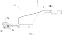
FIG. 2 is a cross-sectional view of a release handle assembly according to an embodiment of the present disclosure. -
FIG. 3 is a cross-sectional view of a child safety seat facing forward in a locked state according to an embodiment of the present disclosure. -
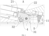
FIG. 4 is an enlarged view of part A inFIG. 3 . -
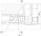
FIG. 5 is an enlarged view of part B inFIG. 3 . -
FIG. 6 is a cross-sectional view of a child safety seat with a positioning plate being disengaged from a positioning groove according to an embodiment of the present disclosure. -
FIG. 7 is an enlarged view of part C inFIG. 6 . -
FIG. 8 is a cross-sectional view of a child safety seat during rotation of a rotary disc according to an embodiment of the present disclosure. -
FIG. 9 is an enlarged view of part D inFIG. 8 . -
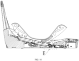
FIG. 10 is a cross-sectional view of a child safety seat facing backward in a locked state according to an embodiment of the present disclosure. -
FIG. 11 is an enlarged view of part E inFIG. 8 . -
FIG. 12 is a partial structural view of a child safety seat according to an embodiment of the present disclosure. - List of reference numerals:
1. base; 11. protruding column; 12. window; 2. rotary disc; 21. positioning groove; 22. brim; 3. release handle assembly; 31. handle body; 311. recessed groove; 312. sliding groove; 313. handle groove; 32. positioning plate; 33. first reset member; 34. rotating shaft; 4. accommodating space; 5. fastener; 6. second reset member. - To make the objectives, technical features, and advantages of the present disclosure more comprehensible, specific embodiments of the present disclosure will be described in detail below with reference to the accompanying drawings.
- In the description of the present disclosure, it should be understood that orientation or position relationships indicated by the terms such as "up" and "down" are orientation or position relationships based on the normal use of the product.
- The terms "first" and "second" are used herein for descriptive purposes, and are not intended to indicate or imply relative importance or implicitly point out the number of the indicated technical features. Therefore, the feature defined by "first" or "second" may explicitly or implicitly include at least one such feature. In the drawings of the embodiments of the present disclosure, a coordinate system YZ is provided, where the positive direction of the Y axis represents front, the negative direction of the Y axis represents rear, the positive direction of the Z axis represents up, and the negative direction of the Z axis represents down.
- An embodiment of the present disclosure provides a seat rotation adjustment structure. Referring to
FIG. 1 ,FIG. 2 ,FIG. 3 ,FIG. 4 , andFIG. 6 toFIG. 11 , the seat rotation adjustment structure includes abase 1 and arotary disc 2 rotatably connected to thebase 1. Arelease handle assembly 3 is mounted on thebase 1. Therelease handle assembly 3 includes ahandle body 31, apositioning plate 32, and afirst reset member 33. Thehandle body 31 is connected to thebase 1 in a forward and backward movable manner. A front end of thepositioning plate 32 is hingedly connected to thehandle body 31, and a rear end of thepositioning plate 32 is connected to thefirst reset member 33. Anaccommodating space 4 configured for restricting a movement of thepositioning plate 32 is formed between therotary disc 2 and thebase 1. A dimension of theaccommodating space 4 in a vertical direction gradually decreases from a rear end to a front end. A plurality ofpositioning grooves 21 configured for engaging with thepositioning plate 32 are provided on therotary disc 2. When thepositioning plate 32 is aligned with apositioning groove 21 of thepositioning grooves 21, thepositioning plate 32 is pushed by thehandle body 31 and thefirst reset member 33 to lock to thepositioning groove 21. After thehandle body 31 is pulled forward to allow thepositioning plate 32 to disengage from thepositioning groove 21, thepositioning plate 32 completely enters theaccommodating space 4, thus achieving a rotation of therotary disc 2 relative to thebase 1. - The
base 1 is configured to be fixedly connected to a seat in a vehicle. Therotary disc 2 is a round disc structure. Therotary disc 2 is configured to be connected to a bottom of a child safety seat. The plurality ofpositioning grooves 21 are circumferentially provided at intervals on therotary disc 2, so that therotary disc 2 can be locked at different positions. In this embodiment, twopositioning grooves 21 are provided, and the twopositioning grooves 21 are symmetrically arranged at a front end and a rear end of therotary disc 2, respectively, so that the child safety seat can be positioned at a position facing a forward direction of the vehicle or at a position facing away from the forward direction of the vehicle. Thepositioning grooves 21 are elongated rectangular grooves, and thepositioning plate 32 is a plate-like structure in the shape of a digit 7, to ensure that when thepositioning plate 32 is engaged with apositioning groove 21 of thepositioning grooves 21, thebase 1 and therotary disc 2 can be firmly fixed relative to each other. Thepositioning plate 32 has a certain thickness, so that thepositioning plate 32 has certain deformation resistance. The thickness of thepositioning plate 32 is slightly less than a width of each of thepositioning grooves 21, so that thepositioning plate 32 can be smoothly locked to or disengaged from thepositioning groove 21. - A top of the
positioning plate 32 is pressed against therotary disc 2 all the time. When therotary disc 2 needs to be unlocked for rotation, a user pulls thehandle body 31 to drive thepositioning plate 32 to move forward. In this process, thepositioning plate 32 is disengaged from thepositioning groove 21, and the top of thepositioning plate 32 receives a downward pressure, so that the rear end of thepositioning plate 32 rotates downward about the front end of thepositioning plate 32. Thefirst reset member 33 is compressed by a pressure from thepositioning plate 32. When the user rotates therotary disc 2, the user releases the force exerted on thehandle body 31. In this case, the rear end of thepositioning plate 32 is pressed against therotary disc 2 and is limited in theaccommodating space 4. When therotary disc 2 rotates until thenext positioning groove 21 is aligned with thepositioning plate 32, thehandle body 31 moves backward toward an original position and drives thepositioning plate 32 to move backward, and the rear end of thepositioning plate 32 rotates upward about the front end of thepositioning plate 32 under an elastic restoring force of thefirst reset member 33 to enter thepositioning groove 21, and is locked to thepositioning groove 21. Thus, a seat position switching operation is completed. - In the seat rotation adjustment structure of this embodiment, the
release handle assembly 3 is arranged on thebase 1, the plurality ofpositioning grooves 21 configured for engaging with thepositioning plate 32 of therelease handle assembly 3 are arranged on therotary disc 2, and through the movement of thehandle body 31 and the restriction of the movement of thepositioning plate 32 by theaccommodating space 4, thepositioning plate 32 can be locked to or disengaged from apositioning groove 21 of thepositioning grooves 21, so that the position of therotary disc 2 can be changed to achieve seat rotation and locking. Such a design involves a simple structure, a small number of parts, and low improvement costs, and is suitable for use in a wide range of applications for improvement. In addition, rotation and locking operations are convenient and stable, so that high operation efficiency is achieved, thereby improving user experience. - Optionally, as shown in
FIG. 1 andFIG. 2 , a recessedgroove 311 configured for mounting thepositioning plate 32 is provided on thehandle body 31, and an upper end and a lower end of thefirst reset member 33 are respectively pressed against thepositioning plate 32 and a bottom of the recessedgroove 311. - The thickness of the
positioning plate 32 is slightly less than a width of the recessedgroove 311, so that thepositioning plate 32 can freely move in the recessedgroove 311. The recessedgroove 311 is a structure with an opening facing upward, a rear end of the recessedgroove 311 is perforated, and the rear end of thepositioning plate 32 extends out of the rear end of the recessedgroove 311, so that the rear end of thepositioning plate 32 can be engaged with therotary disc 2. Thefirst reset member 33 is a compression restoring spring. The recessedgroove 311 is provided with a mounting hole configured for mounting thefirst reset member 33. A boss configured for engaging with thefirst reset member 33 is arranged on thepositioning plate 32. In this embodiment, the recessedgroove 311 is provided on thehandle body 31, and thefirst reset member 33 is mounted between the recessedgroove 311 and thepositioning plate 32, so that thefirst reset member 33 can always stably act on thepositioning plate 32 during the movement of therelease handle assembly 3, thereby ensuring the stability of position switching between the positioningplate 32 and therotary disc 2. - Optionally, as shown in
FIG. 1 andFIG. 2 , therelease handle assembly 3 further includes arotating shaft 34, and thepositioning plate 32 is hingedly connected to thehandle body 31 through the rotatingshaft 34. - Holes for mounting the rotating
shaft 34 are provided on a wall of the recessedgroove 311. A hole for therotating shaft 34 to pass through is also provided on thepositioning plate 32. The front end of thepositioning plate 32 is hingedly connected to thehandle body 31 through the rotatingshaft 34. Such a hinged connection structure is simple and achieves a stable and reliable operation of rotating thepositioning plate 32 relative to thehandle body 31. - Optionally, as shown in
FIG. 1 ,FIG. 2 ,FIG. 3 , andFIG. 4 , a slidinggroove 312 is provided on thehandle body 31, and a protrudingcolumn 11 configured for engaging with the slidinggroove 312 is arranged on thebase 1. - The length direction of the sliding
groove 312 is consistent with the front-rear direction. The protrudingcolumn 11 is arranged to be perpendicular to the front-rear direction. When thehandle body 31 does not receive an external force exerted by the user, thepositioning plate 32 is locked to apositioning groove 21 of thepositioning grooves 21. In this case, the protrudingcolumn 11 is pressed against a front end of the slidinggroove 312. When the user pulls thehandle body 31 to move forward to allow thepositioning plate 32 to disengage from thepositioning groove 21, the protrudingcolumn 11 is pressed against a rear end of the slidinggroove 312. In this embodiment, with the design of the protrudingcolumn 11 and the slidinggroove 312 that are slidably connected to each other, the slidable connection between thehandle body 31 and thebase 1 in the front-rear direction is realized, and thehandle body 31 will not tilt during the sliding process, thereby ensuring that thepositioning plate 32 can be accurately aligned and engaged with thepositioning groove 21 during the state switching of therotary disc 2. - Optionally, as shown in
FIG. 1 ,FIG. 2 ,FIG. 3 , andFIG. 4 , the protrudingcolumn 11 is connected to afastener 5 configured for limiting a vertical movement of thehandle body 31. - The
fastener 5 is configured to limit a vertical movement of the protrudingcolumn 11 relative to the slidinggroove 312, i.e., prevent thehandle body 31 from moving vertically relative to thebase 1. Thefastener 5 is preferably a screw having a threaded rod and a screw cap. A diameter of the screw cap is greater than a width of the slidinggroove 312. - Optionally, as shown in
FIG. 1 ,FIG. 2 ,FIG. 3 , andFIG. 5 , asecond reset member 6 configured for pushing thehandle body 31 to move backward is arranged between thehandle body 31 and thebase 1. - The
second reset member 6 is a compression restoring spring. When the user pulls thehandle body 31 to drive thepositioning plate 32 to move forward, thesecond reset member 6 is compressed by a forward thrust from thehandle body 31. When the user releases the force exerted on thehandle body 31, thehandle body 31 moves backward to the original position under an elastic restoring force of thesecond reset member 6, so that thepositioning plate 32 can enter and be locked to thepositioning groove 21. In this embodiment, with the additional arrangement of thesecond reset member 6 between thehandle body 31 and thebase 1, thehandle body 31 can automatically move back to the original position and push thepositioning plate 32 to lock to thepositioning groove 21 when not receiving an external force exerted by the user. Such a structure is simple and reliable. - Optionally, as shown in
FIG. 1 ,FIG. 2 , andFIG. 12 , ahandle groove 313 is provided at a rear end of thehandle body 31, and awindow 12 configured for exposing thehandle groove 313 is provided on thebase 1. - The
handle groove 313 is provided at a front end of thehandle body 31, and the correspondingwindow 12 is also provided at a front end of thebase 1, so as not to affect the user's operation on thehandle body 31 during the state switching of the child safety seat. Thehandle groove 313 provided also makes it convenient for the user to operate thehandle body 31. - Optionally, as shown in
FIG. 3 andFIG. 4 , abrim 22 is arranged on a peripheral wall of therotary disc 2, and theaccommodating space 4 is formed between thebrim 22 and thebase 1. - The
brim 22 is located outside thepositioning grooves 21. When thepositioning plate 32 is locked to apositioning groove 21 of thepositioning grooves 21, the top of thepositioning plate 32 is pressed against both thepositioning groove 21 and thebrim 22 under the elastic restoring force of thefirst reset member 33. When thepositioning plate 32 is disengaged from thepositioning groove 21 and therotary disc 2 is rotated, the top of thepositioning plate 32 is pressed against thebrim 22, and the rear end of thepositioning plate 32 is pressed against an edge of thepositioning groove 21. Through holes are evenly provided at intervals on thebrim 22 to reduce the overall weight of therotary disc 2, making it convenient for the user to rotate the child safety seat. - Optionally, as shown in
FIG. 3 andFIG. 4 , a distance between thebrim 22 and thebase 1 gradually decreases from a rear end to a front end. - The
accommodating space 4 gradually shrinks from a rear end to a front end, i.e., therotary disc 2 is inclined downward from a rear end to a front end relative to thebase 1. In this way, during thehandle body 31 driving thepositioning plate 32 to move forward, because space for vertical movement of thepositioning plate 32 in theaccommodating space 4 is becoming smaller, the rear end of thepositioning plate 32 can rotate downward about the front end of thepositioning plate 32 under a pressure from thebrim 22 until thepositioning plate 32 is completely disengaged from thepositioning groove 21, so that therotary disc 2 can rotate relative to thebase 1. In this embodiment, theaccommodating space 4 gradually shrinking from a rear end to a front end is designed by using the positional relationship between thebrim 22 and thebase 1, so that in the process of moving forward, thepositioning plate 32 can be rotated by a pressure from therotary disc 2 and limited in theaccommodating space 4, thereby ensuring a smooth rotation of therotary disc 2. Such a structure is simple and easy to operate. - Another embodiment of the present disclosure provides a child safety seat, including the seat rotation adjustment structure described above.
- A fixing hook configured for mounting an edge of the
rotary disc 2 and a positioning mechanism configured for rotatably connecting therotary disc 2 to thebase 1 are mounted in thebase 1. Therotary disc 2 is mounted with an axis center on the positioning mechanism as the center of circle. A slide rail fixing plate is fixed to therotary disc 2 through a fastening screw. The child safety seat is fixed to the slide rail fixing plate. When therotary disc 2 is rotated, the child safety seat can be driven to rotate through the slide rail fixing plate. - In the child safety seat of this embodiment, the
release handle assembly 3 is arranged on thebase 1, the plurality ofpositioning grooves 21 configured for engaging with thepositioning plate 32 of therelease handle assembly 3 are arranged on therotary disc 2, and through the movement of thehandle body 31 and the restriction of the movement of thepositioning plate 32 by theaccommodating space 4, thepositioning plate 32 can be locked to or disengaged from apositioning groove 21 of thepositioning grooves 21, so that the position of therotary disc 2 can be changed to achieve seat rotation and locking. Such a design involves a simple structure, a small number of parts, and low improvement costs, and is suitable for use in a wide range of applications for improvement. In addition, rotation and locking operations are convenient and stable, so that high operation efficiency is achieved, thereby improving user experience. - Although the present disclosure has been disclosed above, the scope of protection of the present disclosure is not limited thereto. Those skilled in the art can make various changes and modifications without departing from the spirit and scope of the present disclosure. Such changes and modifications also fall within the scope of protection of the present disclosure.
Claims (10)
- A seat rotation adjustment structure, characterized by comprising a base (1) and a rotary disc (2) rotatably connected to the base (1), wherein a release handle assembly (3) is mounted on the base (1); the release handle assembly (3) comprises a handle body (31), a positioning plate (32), and a first reset member (33); the handle body (31) is connected to the base (1) in a forward and backward movable manner; a front end of the positioning plate (32) is hingedly connected to the handle body (31), and a rear end of the positioning plate (32) is connected to the first reset member (33); an accommodating space (4) configured for restricting a movement of the positioning plate (32) is formed between the rotary disc (2) and the base (1); a plurality of positioning grooves (21) configured for engaging with the positioning plate (32) are provided on the rotary disc (2); when the positioning plate (32) is aligned with a positioning groove (21) of the positioning grooves (21), the positioning plate (32) is pushed by the handle body (31) and the first reset member (33) to lock to the positioning groove (21); and after the handle body (31) is pulled forward to allow the positioning plate (32) to disengage from the positioning groove (21), the positioning plate (32) completely enters the accommodating space (4), to achieve a rotation of the rotary disc (2) relative to the base (1).
- The seat rotation adjustment structure according to claim 1, characterized in that a recessed groove (311) configured for mounting the positioning plate (32) is provided on the handle body (31), and an upper end and a lower end of the first reset member (33) are respectively pressed against the positioning plate (32) and a bottom of the recessed groove (311).
- The seat rotation adjustment structure according to claim 1, characterized in that the release handle assembly (3) further comprises a rotating shaft (34), and the positioning plate (32) is hingedly connected to the handle body (31) through the rotating shaft (34).
- The seat rotation adjustment structure according to claim 1, characterized in that a sliding groove (312) is provided on the handle body (31), and a protruding column (11) configured for engaging with the sliding groove (312) is arranged on the base (1).
- The seat rotation adjustment structure according to claim 4, characterized in that the protruding column (11) is connected to a fastener (5) configured for limiting a vertical movement of the handle body (31).
- The seat rotation adjustment structure according to claim 1, characterized in that a second reset member (6) configured for pushing the handle body (31) to move backward is arranged between the handle body (31) and the base (1).
- The seat rotation adjustment structure according to claim 1, characterized in that a handle groove (313) is provided at a rear end of the handle body (31), and a window (12) configured for exposing the handle groove (313) is provided on the base (1).
- The seat rotation adjustment structure according to any one of claims 1 to 7, characterized in that a brim (22) is arranged on a peripheral wall of the rotary disc (2), and the accommodating space (4) is formed between the brim (22) and the base (1).
- The seat rotation adjustment structure according to claim 8, characterized in that a distance between the brim (22) and the base (1) gradually decreases from a rear end to a front end.
- A child safety seat, characterized by comprising the seat rotation adjustment structure according to any one of claims 1 to 9.
Applications Claiming Priority (2)
| Application Number | Priority Date | Filing Date | Title |
|---|---|---|---|
| CN202122108810.7U CN216153636U (en) | 2021-09-02 | 2021-09-02 | Seat rotation regulation structure and child safety seat |
| PCT/CN2022/101085 WO2023029688A1 (en) | 2021-09-02 | 2022-06-24 | Seat rotation adjustment structure and child safety seat |
Publications (3)
| Publication Number | Publication Date |
|---|---|
| EP4397535A1 true EP4397535A1 (en) | 2024-07-10 |
| EP4397535A4 EP4397535A4 (en) | 2025-02-19 |
| EP4397535B1 EP4397535B1 (en) | 2026-04-22 |
Family
ID=80841541
Family Applications (1)
| Application Number | Title | Priority Date | Filing Date |
|---|---|---|---|
| EP22862829.3A Active EP4397535B1 (en) | 2021-09-02 | 2022-06-24 | Seat rotation adjustment structure and child safety seat |
Country Status (3)
| Country | Link |
|---|---|
| EP (1) | EP4397535B1 (en) |
| CN (1) | CN216153636U (en) |
| WO (1) | WO2023029688A1 (en) |
Families Citing this family (7)
| Publication number | Priority date | Publication date | Assignee | Title |
|---|---|---|---|---|
| CN216153636U (en) * | 2021-09-02 | 2022-04-01 | 宁波宝贝第一母婴用品有限公司 | Seat rotation regulation structure and child safety seat |
| CN115556649B (en) * | 2022-10-20 | 2025-05-27 | 宁波宝贝第一母婴用品有限公司 | Child safety seat with linkage release function |
| CN218172061U (en) * | 2022-10-20 | 2022-12-30 | 宁波宝贝第一母婴用品有限公司 | Adjusting structure for realizing disassembly and rotary lock release of chair body and child safety seat |
| CN115556648B (en) * | 2022-10-20 | 2025-05-27 | 宁波宝贝第一母婴用品有限公司 | A child safety seat capable of being released in linkage with any rotation angle |
| CN116639029B (en) * | 2023-06-14 | 2025-12-23 | 宝钜(中国)儿童用品有限公司 | Child safety seats |
| CN220842286U (en) * | 2023-09-07 | 2024-04-26 | 麦克英孚(宁波)婴童用品有限公司 | Chair body rotating structure and child safety seat |
| CN117246202A (en) * | 2023-09-27 | 2023-12-19 | 麦克英孚(宁波)婴童用品有限公司 | A chair body angle adjustment structure and a child safety seat |
Family Cites Families (8)
| Publication number | Priority date | Publication date | Assignee | Title |
|---|---|---|---|---|
| JPH04124530U (en) * | 1991-04-26 | 1992-11-13 | 株式会社東海理化電機製作所 | child seat |
| JPH10229931A (en) * | 1996-12-19 | 1998-09-02 | Araco Corp | Child chair |
| US6199949B1 (en) * | 2000-07-31 | 2001-03-13 | Dasilva Eric S. | Child safety seat |
| WO2019046990A1 (en) * | 2017-09-07 | 2019-03-14 | 蒙祖胜 | Child's safety seat |
| CN209240929U (en) * | 2018-10-29 | 2019-08-13 | 宁波后乐婴童用品有限公司 | A kind of child safety seat rotating mechanism |
| CN210591512U (en) * | 2019-07-11 | 2020-05-22 | 宁波无忧婴童用品有限公司 | Child safety seat with chair back angle adjusting mechanism |
| CN214057313U (en) * | 2020-12-18 | 2021-08-27 | 宁波智贝儿童用品有限公司 | Rotating mechanism of child safety seat |
| CN216153636U (en) * | 2021-09-02 | 2022-04-01 | 宁波宝贝第一母婴用品有限公司 | Seat rotation regulation structure and child safety seat |
-
2021
- 2021-09-02 CN CN202122108810.7U patent/CN216153636U/en active Active
-
2022
- 2022-06-24 WO PCT/CN2022/101085 patent/WO2023029688A1/en not_active Ceased
- 2022-06-24 EP EP22862829.3A patent/EP4397535B1/en active Active
Also Published As
| Publication number | Publication date |
|---|---|
| WO2023029688A1 (en) | 2023-03-09 |
| EP4397535A4 (en) | 2025-02-19 |
| EP4397535B1 (en) | 2026-04-22 |
| CN216153636U (en) | 2022-04-01 |
Similar Documents
| Publication | Publication Date | Title |
|---|---|---|
| EP4397535A1 (en) | Seat rotation adjustment structure and child safety seat | |
| US20240133233A1 (en) | Locking seat and simple telescopic door fence with same | |
| US20230211709A1 (en) | Child safety seat and detachable side impact protection block | |
| TWI750820B (en) | Backrest locking mechanism and child safety seat therewith | |
| EP4328083A1 (en) | Supporting leg structure and child safety seat | |
| CN114801919A (en) | Baby carrier | |
| CN113619466B (en) | Cup stand assembly | |
| EP4227540A1 (en) | Storable fan | |
| EP4292876A1 (en) | Supporting leg positioning structure and child safety seat | |
| CN111900915B (en) | A solar panel support structure and solar module | |
| EP4596315A2 (en) | Angle adjustment structure and child carrier | |
| CN215332115U (en) | Movable automobile armrest unlocking mechanism | |
| CN220817131U (en) | Fast-assembling structure and fast-assembling seat | |
| CN114919475B (en) | One-key unlocking rotation adjusting structure of child safety seat | |
| CN217812877U (en) | Convenient to use's padlock | |
| CN110466398A (en) | Headrest and seat back connection mechanism and child safety seat | |
| CN215674544U (en) | Supporting mechanism and periscope | |
| JP4304044B2 (en) | Chair armrest equipment | |
| CN213297510U (en) | Puzzle lock | |
| CN209799634U (en) | Lock catch for safety lock | |
| CN216331620U (en) | Big handrail of vehicle back row | |
| CN218488460U (en) | Handrail device and mobile robot | |
| CN219466631U (en) | Locking device and pedal with same | |
| CN214304681U (en) | Locking mechanism and outdoor water heater | |
| CN221519852U (en) | Tilting mechanism and end bucket seatpad device |
Legal Events
| Date | Code | Title | Description |
|---|---|---|---|
| STAA | Information on the status of an ep patent application or granted ep patent |
Free format text: STATUS: THE INTERNATIONAL PUBLICATION HAS BEEN MADE |
|
| PUAI | Public reference made under article 153(3) epc to a published international application that has entered the european phase |
Free format text: ORIGINAL CODE: 0009012 |
|
| STAA | Information on the status of an ep patent application or granted ep patent |
Free format text: STATUS: REQUEST FOR EXAMINATION WAS MADE |
|
| 17P | Request for examination filed |
Effective date: 20240325 |
|
| AK | Designated contracting states |
Kind code of ref document: A1 Designated state(s): AL AT BE BG CH CY CZ DE DK EE ES FI FR GB GR HR HU IE IS IT LI LT LU LV MC MK MT NL NO PL PT RO RS SE SI SK SM TR |
|
| DAV | Request for validation of the european patent (deleted) | ||
| DAX | Request for extension of the european patent (deleted) | ||
| A4 | Supplementary search report drawn up and despatched |
Effective date: 20250120 |
|
| RIC1 | Information provided on ipc code assigned before grant |
Ipc: B60N 2/28 20060101AFI20250114BHEP |
|
| GRAP | Despatch of communication of intention to grant a patent |
Free format text: ORIGINAL CODE: EPIDOSNIGR1 |
|
| STAA | Information on the status of an ep patent application or granted ep patent |
Free format text: STATUS: GRANT OF PATENT IS INTENDED |
|
| INTG | Intention to grant announced |
Effective date: 20251117 |
|
| GRAS | Grant fee paid |
Free format text: ORIGINAL CODE: EPIDOSNIGR3 |
|
| GRAA | (expected) grant |
Free format text: ORIGINAL CODE: 0009210 |
|
| STAA | Information on the status of an ep patent application or granted ep patent |
Free format text: STATUS: THE PATENT HAS BEEN GRANTED |
|
| AK | Designated contracting states |
Kind code of ref document: B1 Designated state(s): AL AT BE BG CH CY CZ DE DK EE ES FI FR GB GR HR HU IE IS IT LI LT LU LV MC MK MT NL NO PL PT RO RS SE SI SK SM TR |
|
| REG | Reference to a national code |
Ref country code: CH Ref legal event code: F10 Free format text: ST27 STATUS EVENT CODE: U-0-0-F10-F00 (AS PROVIDED BY THE NATIONAL OFFICE) Effective date: 20260422 Ref country code: GB Ref legal event code: FG4D |