EP4397534A1 - Distributed-type power generation and power supply system for traction network, and control method - Google Patents
Distributed-type power generation and power supply system for traction network, and control method Download PDFInfo
- Publication number
- EP4397534A1 EP4397534A1 EP22866020.5A EP22866020A EP4397534A1 EP 4397534 A1 EP4397534 A1 EP 4397534A1 EP 22866020 A EP22866020 A EP 22866020A EP 4397534 A1 EP4397534 A1 EP 4397534A1
- Authority
- EP
- European Patent Office
- Prior art keywords
- power generation
- generation apparatus
- traction
- power
- traction network
- Prior art date
- Legal status (The legal status is an assumption and is not a legal conclusion. Google has not performed a legal analysis and makes no representation as to the accuracy of the status listed.)
- Pending
Links
Images


Classifications
-
- B—PERFORMING OPERATIONS; TRANSPORTING
- B60—VEHICLES IN GENERAL
- B60M—POWER SUPPLY LINES, AND DEVICES ALONG RAILS, FOR ELECTRICALLY- PROPELLED VEHICLES
- B60M3/00—Feeding power to supply lines in contact with collector on vehicles; Arrangements for consuming regenerative power
-
- B—PERFORMING OPERATIONS; TRANSPORTING
- B60—VEHICLES IN GENERAL
- B60M—POWER SUPPLY LINES, AND DEVICES ALONG RAILS, FOR ELECTRICALLY- PROPELLED VEHICLES
- B60M1/00—Power supply lines for contact with collector on vehicle
- B60M1/12—Trolley lines; Accessories therefor
- B60M1/13—Trolley wires
-
- B—PERFORMING OPERATIONS; TRANSPORTING
- B60—VEHICLES IN GENERAL
- B60M—POWER SUPPLY LINES, AND DEVICES ALONG RAILS, FOR ELECTRICALLY- PROPELLED VEHICLES
- B60M3/00—Feeding power to supply lines in contact with collector on vehicles; Arrangements for consuming regenerative power
- B60M3/06—Arrangements for consuming regenerative power
-
- H—ELECTRICITY
- H02—GENERATION; CONVERSION OR DISTRIBUTION OF ELECTRIC POWER
- H02J—ELECTRIC POWER NETWORKS; CIRCUIT ARRANGEMENTS OR SYSTEMS FOR SUPPLYING OR DISTRIBUTING ELECTRIC POWER; SYSTEMS FOR STORING ELECTRIC ENERGY
- H02J3/00—Circuit arrangements for AC mains or AC distribution networks
- H02J3/38—Arrangements for feeding a single network from two or more generators or sources in parallel; Arrangements for feeding already energised networks from additional generators or sources in parallel
Definitions
- the neutral section of the traction power supply system forms a non-electric region, which causes interruption of power supply, and is a bottleneck for restricting the development of electrified railways, and implementing long-distance co-phase power supply can reduce or even eliminate the neutral section to remove the non-electric region.
- the implementation of long-distance co-phase power supply can cross these difficult sections and solve the problem of traction power supply.
- the proposed solution for new energy and renewable energy to access electrified railways is to concentrate on one place to generate electricity, or generate electricity nearby, or generate electricity at one place far away from traction substation, then a traction bus is connected to the traction substation centrally.
- the problem solved is the consumption of new energy and renewable energy and the peak elimination and valley filling of traction load, without considering the linear distribution of railway lines and the coexistence of multiple power generation systems. Therefore, how to connect multiple distributed-type new energy and renewable energy power generation systems into the traction power supply system has become a problem worth studying.
- the distributed-type new energy and renewable energy power generation system When the distributed-type new energy and renewable energy power generation system is connected to the traction network, it will involve complex connection structures and control methods. When there are new energy generation power and traction substation power at the same time, how to control and use the new energy generation power and the traction substation power to meet the needs of new energy consumption nearby, reduce the phenomenon of "wind and light abandonment" and improve the utilization rate of new energy power generation is also an urgent problem to be solved after the new energy power generation system is connected to the grid.
- Chinese Patent No.: 202110028103.9 discloses "An co-phase traction power supply and remote power generation grid-connected system and control method", which involves a remote power generation system far away from a traction substation, and the power generation system is connected to the traction substation through power supply lines.
- this form is extended to many remote grid-connected power generation systems, it is characterized by a radial structure centered on a traction substation, and all power generation systems need to be connected to the traction substation through their own power supply lines, which is obviously not suitable for the connection of linear distributed power generation along the railway, otherwise the power supply lines will be too long and wasted.
- a distributed-type power generation and power supply system for a traction network includes a traction network and an co-phase traction substation TS connected with the traction network, a traction bus TBT of the co-phase traction substation TS is connected with a contact network T line of the traction network by a feeder line FP, a return line FN of the co-phase traction substation TS is connected with a rail R, the traction bus TBT is provided with a voltage transformer PT and the feeder line FP is provided with a current transformer CT, the traction network is provided with a switching station, and the distributed-type power generation and power supply system for the traction network further includes a power generation apparatus arranged along the railway direction, the power generation apparatus accesses the traction network through the switching station; a central coordinated controller CCC is provided at the co-phase traction substation TS, a measurement-control terminal of the central coordinated controller CCC is connected with a measurement-control terminal of the power generation apparatus
- the AC-DC conversion apparatus GCi when used alone, is present as a reactive generator.
- the specific conditions for distinguishing the power consumption state and the power generation state are: the instantaneous total power of the traction network is greater than 0, which is recorded as the power consumption state; when the sum of the energy generated by all the new energy generation apparatuses of the traction network and the regenerative energy of the train is greater than the sum of the traction energy of the train, the instantaneous total power of the traction network is less than 0, which is recorded as the power generation state.
- the working principle of the invention is that according to the distributed characteristics of new energy and renewable energy in the corridor along the railway line, a plurality of power generation apparatuses are accessed into the traction network in a distributed manner by using the switching station arranged along the traction network, and the active and reactive power output of the power generation apparatuses are distributed and controlled by detecting the superimposed power of the power generation apparatuses and electric locomotives, so as to realize the direct power supply of the new energy and renewable energy to the traction load, support the traction network voltage in real time, prolong the power supply distance, and improve the utilization rate of regenerated electric energy of trains and the utilization rate of power generation of new energy and renewable energy.
- the present embodiment provides a distributed-type power generation and power supply system for a traction network, including a traction network and an co-phase traction substation TS connected with the traction network, the traction network is erected above the running rail of the railway, a traction bus TBT of the co-phase traction substation TS is connected with a contact network T line of the traction network by a feeder line FP, a return line FN of the co-phase traction substation TS is connected with a rail R, the traction bus TBT is provided with a voltage transformer PT and the feeder line FP is provided with a current transformer CT, the traction network is provided with a switching station, and the distributed-type power generation and power supply system for the traction network further includes a power generation apparatus arranged in a corridor along the railway line, the power generation apparatus accesses the traction network through the switching station in a distributed manner.
- the combined co-phase power supply can be adopted to compensate the power quality within the national standard.
- Single and single-phase combined co-phase power supply is recommended, and single and three-phase combined co-phase power supply can be considered when existing conditions are used.
- the embodiment provides a control method of the distributed-type power generation and power supply system for the traction network based on Embodiment 1, which is applied to a central coordinated controller CCC, and is implemented by the following technical solution:
- the distributed-type power generation and power supply system for the traction network includes n power generation apparatuses, and specifically, the power generation apparatuses are denoted as a power generation apparatus SG1, a power generation apparatus SG2,..., a power generation apparatus SGi,..., a power generation apparatus SGn, and the method includes:
Landscapes
- Engineering & Computer Science (AREA)
- Mechanical Engineering (AREA)
- Power Engineering (AREA)
- Supply And Distribution Of Alternating Current (AREA)
Abstract
Description
- This application claims the benefit of
Chinese Patent Application 202111046377.7, filed on September 08, 2021 - The present invention relates to the technical field of alternating current gasification railway traction power supply, and relates to a distributed-type power generation and power supply system for a traction network.
- There have been a large number of successful application cases of new energy and renewable energy generation in power system, and the railway system has also been preliminarily studied. New energy and renewable energy power generation is promoted and applied along the railways according to the principles of adapting to local conditions and multi-energy complementation.
- The neutral section of the traction power supply system forms a non-electric region, which causes interruption of power supply, and is a bottleneck for restricting the development of electrified railways, and implementing long-distance co-phase power supply can reduce or even eliminate the neutral section to remove the non-electric region. Especially for difficult sections with weak external power sources and limited geographical conditions, such as the Sichuan-Tibet railway, the implementation of long-distance co-phase power supply can cross these difficult sections and solve the problem of traction power supply.
- Currently, the proposed solution for new energy and renewable energy to access electrified railways is to concentrate on one place to generate electricity, or generate electricity nearby, or generate electricity at one place far away from traction substation, then a traction bus is connected to the traction substation centrally. The problem solved is the consumption of new energy and renewable energy and the peak elimination and valley filling of traction load, without considering the linear distribution of railway lines and the coexistence of multiple power generation systems. Therefore, how to connect multiple distributed-type new energy and renewable energy power generation systems into the traction power supply system has become a problem worth studying.
- When the distributed-type new energy and renewable energy power generation system is connected to the traction network, it will involve complex connection structures and control methods. When there are new energy generation power and traction substation power at the same time, how to control and use the new energy generation power and the traction substation power to meet the needs of new energy consumption nearby, reduce the phenomenon of "wind and light abandonment" and improve the utilization rate of new energy power generation is also an urgent problem to be solved after the new energy power generation system is connected to the grid.
-
Chinese Patent No.: 202110028103.9 - It is an object of the present invention to provide a distributed-type power generation and power supply system for a traction network, and the system can effectively solve the technical problem of direct grid-connected access of distributed-type power generation apparatuses along railways to the traction network to participate in traction power supply and capacity distribution and control.
- The object of the present invention is achieved by the following technical solution:
A distributed-type power generation and power supply system for a traction network includes a traction network and an co-phase traction substation TS connected with the traction network, a traction bus TBT of the co-phase traction substation TS is connected with a contact network T line of the traction network by a feeder line FP, a return line FN of the co-phase traction substation TS is connected with a rail R, the traction bus TBT is provided with a voltage transformer PT and the feeder line FP is provided with a current transformer CT, the traction network is provided with a switching station, and the distributed-type power generation and power supply system for the traction network further includes a power generation apparatus arranged along the railway direction, the power generation apparatus accesses the traction network through the switching station; a central coordinated controller CCC is provided at the co-phase traction substation TS, a measurement-control terminal of the central coordinated controller CCC is connected with a measurement-control terminal of the power generation apparatus via an optical fiber pair, a measurement terminal of the voltage transformer PT and a measurement terminal of the current transformer CT are connected with an input terminal of the central coordinated controller CCC. - The number of the switching stations is n, and specifically, the switching stations are denoted as a switching station ST1, a switching station ST2,..., a switching station STi,..., a switching station STn, wherein n ≥ 1, i = 1, 2, 3,..., n; a sectionalizer SEi is connected in series with the contact network T line at an exit of the switching station STi to section the contact network T line; two sides of the sectionalizer SEi are connected with a sectionalized bus BSi via a connecting line Lli, and a connecting line L2i, respectively; the voltage of the sectionalized bus BSi of the switching station STi provides a support voltage for the power generation apparatus.
- The number of the power generation apparatuses is n, and specifically, the power generation apparatuses are denoted as a power generation apparatus SG1, a power generation apparatus SG2,..., a power generation apparatus SGi,..., a power generation apparatus SGn, wherein n ≥ 1, i = 1, 2, 3,..., n; the power generation apparatus SGi is connected with the sectionalized bus BSi of the switching state STi by a connection SPi; the sectionalized bus BSi is provided with a voltage transformer PTi; the measurement-control terminal of the central coordinated controller CCC is connected with the measurement-control terminals of the power generation apparatus SG1, the power generation apparatus SG2, the power generation apparatus SGi..., the power generation apparatus SGn via the optical fiber pair sS1, the optical fiber pair sS2,..., the optical fiber pair sSi,..., and the optical fiber pair sSn, respectively, measurement terminals of the voltage transformer PT1, the voltage transformer PT2,..., the voltage transformer PTi,..., the voltage transformer PTn are connected with the input terminal of the central coordinated controller CCC via an optical fiber s1, an optical fiber s2, an optical fiber si,..., and an optical fiber sn, respectively.
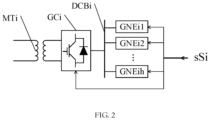
- The power generation apparatus SGi comprises a matching transformer MTi, an AC-DC conversion apparatus GCi and a new energy generation apparatus GNEi; the number of the new energy generation apparatuses GNEi is h, h ≥ 1, and specifically, the new energy generation apparatus are denoted as a new energy generation apparatus GNEi1, a new energy generation apparatus GNEi2,..., a new energy generation apparatus GNEih; DC sides of the new energy generation apparatus GNEi1, the new energy generation apparatus GNEi2,..., the new energy generation apparatus GNEih are connected in parallel with a DC bus DCBi, and then are connected with a DC port of the AC-DC conversion apparatus GCi; a secondary winding of the matching transformer MTi is connected with an AC port of the AC-DC conversion apparatus GCi, and one end of a primary winding of the matching transformer MTi is connected with the connection SPi and the other end is connected with the rail R, wherein the measurement-control terminal of the central coordinated controller CCC is connected with the measurement-control terminal of the AC-DC conversion apparatus GCi and the measurement-control terminals of the h new energy generation apparatuses GNEi via the optical fiber pair sSi.
- The AC-DC conversion apparatus GCi, when used alone, is present as a reactive generator.
- Installed capacities of the power generation apparatus SG1, the power generation apparatus SG2,..., the power generation apparatus SGi,..., the power generation apparatus SGn correspond to S1, S2,..., Si,..., Sn, respectively, maximum active power generation capacities correspond to E1, E2,..., Ei,..., En, respectively, and maximum reactive compensation capacities correspond to Q1, Q2,..., Qi,..., Qn, respectively, and

- The new energy generation apparatus GNEi is one or several of a photovoltaic power generation apparatus, a photothermal power generation apparatus, a hydrogen power generation apparatus, a wind power generation apparatus, or a biochemical energy power generation apparatus.
- Another object of the present invention is to provide a control method of a distributed-type power generation and power supply system for a traction network, which effectively solves the technical problem of controlling the grid-connection of a distributed-type new energy power generation apparatus with the traction network and supporting the voltage of the traction network.
- Another object of the present invention is achieved by the following technical solution:
a control method of a distributed-type power generation and power supply system for a traction network, the method including:
calculating, by a central coordinated controller CCC, a total installed capacity S of power generation apparatuses based on installed capacities S1, S2,..., Si,..., Sn of the power generation apparatus SG1, the power generation apparatus SG2,..., the power generation apparatus SGi,..., the power generation apparatus SGn which access the traction network by a switching station arranged in the traction network, wherein,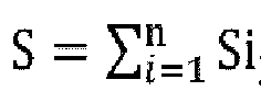
- Acquiring, by the central coordinated controller CCC, a voltage UPi of the switching station STi through a voltage transformer PTi; and controlling the power generating apparatus SGi to emit a reactive compensation capacity qi to compensate for a power factor of the traction network and the network voltage of the switching station based on the voltage UPi, wherein the absolute value of qi satisfies |qi|≤ Qi.
- Judging, by the central coordinated controller CCC, whether the power generation apparatus has a failure or has no power generation condition, when the power generation apparatus has a failure or does not have a power generation condition, causing the power generation apparatus to exit operation, wherein p power generation apparatuses among the power generation apparatus SG1, the power generation apparatus SG2,..., the power generation apparatus SGi,..., the power generation apparatus SGn fail or do not have a power generation condition, which are collectively referred to as a failed power generation apparatus SGkl, a failed power generation apparatus SGk2,..., a failed power generation apparatus SGkz,..., a failed power generation apparatus SGkp (
kzE f 
determining the total active power generation capacity Ea of the power generation apparatuses that do not exit operation based on the instantaneous total power of the traction network comprising n-p power generation apparatuses and the total installed capacity Sa of the power generation apparatuses, wherein Ea ≤ Sa; and controlling the active power generation capacity of the power generation apparatus SGi to be Eai, wherein Eai = Ea * Si/Sa; and when a power generation apparatus fails or does not have a power generation condition, then: reacquiring, by the central coordinated controller CCC, the voltage UPai of the switching station STi corresponding to the power generation apparatus SGi that has not exited operation through the voltage transformer PTi; controlling the power generation apparatus SGi to generate a reactive compensation capacity qai based on the voltage UPai to compensate for the power factor of the traction network and the network voltage of the switching station at this time, wherein the absolute value of qai satisfies |qai| ≤ Qi, and the power generation apparatus SGi is capable of controlling either the active power generation capacity or the reactive compensation capacity , respectively, or controlling both the active power generation capacity and the reactive compensation capacity simultaneously. - The specific conditions for distinguishing the power consumption state and the power generation state are: the instantaneous total power of the traction network is greater than 0, which is recorded as the power consumption state; when the sum of the energy generated by all the new energy generation apparatuses of the traction network and the regenerative energy of the train is greater than the sum of the traction energy of the train, the instantaneous total power of the traction network is less than 0, which is recorded as the power generation state.
- The working principle of the invention is that according to the distributed characteristics of new energy and renewable energy in the corridor along the railway line, a plurality of power generation apparatuses are accessed into the traction network in a distributed manner by using the switching station arranged along the traction network, and the active and reactive power output of the power generation apparatuses are distributed and controlled by detecting the superimposed power of the power generation apparatuses and electric locomotives, so as to realize the direct power supply of the new energy and renewable energy to the traction load, support the traction network voltage in real time, prolong the power supply distance, and improve the utilization rate of regenerated electric energy of trains and the utilization rate of power generation of new energy and renewable energy.
- Compared with the prior art, the beneficial effects of the present invention are:
- First, new energy and renewable energy can be connected to the traction network in a distributed manner, which is conducive to the direct integration of new energy and renewable energy along the railway into the traction network to participate in traction power supply, without connecting the new energy and renewable energy power generation system to the traction substation through their respective power supply lines;
- Second, it is conducive to supporting the traction network voltage along the railway line in real time and providing good power supply conditions for train traffic; and
- Third, it is conducive to extending the power supply distance, improving the utilization rate of new energy and renewable energy while improving the utilization rate of renewable energy, and reducing the phenomenon of "wind and light abandonment".
-
-
FIG. 1 is a schematic structural diagram of the present invention. -
FIG. 2 is a schematic structural diagram of the power generation apparatus of the present invention. -
FIG. 3 is a flowchart of the control method of the present invention. - In order for those skilled in the art to better understand the technical solutions of the present invention, the present invention is further described below with reference to the accompanying drawings and the detailed embodiments.
- As shown in
FIG. 1 , the present embodiment provides a distributed-type power generation and power supply system for a traction network, including a traction network and an co-phase traction substation TS connected with the traction network, the traction network is erected above the running rail of the railway, a traction bus TBT of the co-phase traction substation TS is connected with a contact network T line of the traction network by a feeder line FP, a return line FN of the co-phase traction substation TS is connected with a rail R, the traction bus TBT is provided with a voltage transformer PT and the feeder line FP is provided with a current transformer CT, the traction network is provided with a switching station, and the distributed-type power generation and power supply system for the traction network further includes a power generation apparatus arranged in a corridor along the railway line, the power generation apparatus accesses the traction network through the switching station in a distributed manner. - A central coordinated controller CCC is provided at the co-phase traction substation TS, a measurement-control terminal of the central coordinated controller CCC is connected with a measurement-control terminal of the power generation apparatus via an optical fiber pair, a measurement terminal of the voltage transformer PT and a measurement terminal of the current transformer CT are connected with an input terminal of the central coordinated controller CCC.
- In the embodiment, the co-phase traction substation can cancel the neutral section at the outlet of the substation to realize the co-phase power supply (the specific solution of the co-phase traction substation can refer to the patent application documents or non-patent documents related to the co-phase power supply). Since the power supply distance of the traction network will be increased after the neutral section is cancelled, in order to increase the power supply reliability, the embodiment is provided with a switching station, and the new energy power generation system in the embodiment accesses the traction network through the switching station in a distributed manner. On the one hand, nearby consumption is realized to promote the green development of the railway system, on the other hand, it can avoid the line loss problem caused by long-distance transmission to the substation in the solution of centralized access to the traction network through the substation, thus improving the utilization efficiency of new energy.
- Preferably, the number of the switching stations is n, and specifically, the switching stations are denoted as a switching station ST1, a switching station ST2,..., a switching station STi,..., a switching station STn; a sectionalizer SEi is connected in series with the contact network T line at an exit of the switching station STi to section the contact network T line and make the train pass through without power; two sides of the sectionalizer SEi are connected with a sectionalized bus BSi via a connecting line L1i, and a connecting line L2i, respectively, wherein n ≥ 1, i = 1, 2, 3,..., n; the voltage of the sectionalized bus BSi of the switching station provides a support voltage for the power generation apparatus.
- In the embodiment, the switching station is arranged on the line to ensure the reliability and flexibility of power supply and reduce the power failure range. Under normal operation, the switch of the switching station is in a connected state, and only under working conditions such as fault or maintenance, the switch of the switching station is in a disconnected state. The switching station is different from a section post provided with the neutral section. The section post is a facility that divides the traction network into different power supply sub-sections. Usually, the section post is set at the power supply boundary between two adjacent traction substations. When a traction substation loses power due to fault, the switch of the section post can be closed for cross-zone power supply. Under normal operation, the switch of the section post is in a disconnected state. In addition, in the double-track section, parallel operation at the ends of the uplink and downlink lines can be implemented in the section post.
- Preferably, the number of the power generation apparatuses is n, n ≥ 1, i = 1, 2, 3,..., n, and specifically, the power generation apparatuses are denoted as a power generation apparatus SG1, a power generation apparatus SG2,..., a power generation apparatus SGi,..., a power generation apparatus SGn; the power generation apparatus SGi is connected with the sectionalized bus BSi of the switching state STi by a connection SPi; the sectionalized bus BSi is provided with a voltage transformer PTi; the measurement-control terminal of the central coordinated controller CCC is connected with the measurement-control terminals of the power generation apparatus SG1, the power generation apparatus SG2, the power generation apparatus SGi..., the power generation apparatus SGn via the optical fiber pair sS1, the optical fiber pair sS2,..., the optical fiber pair sSi,..., and the optical fiber pair sSn, respectively, measurement terminals of the voltage transformer PT1, the voltage transformer PT2,..., the voltage transformer PTi,..., the voltage transformer PTn are connected with the input terminal of the central coordinated controller CCC via an optical fiber s1, an optical fiber s2, an optical fiber si,..., and an optical fiber sn, respectively.
- In implementing this embodiment, the power generation apparatus accesses the switching station nearby, so as to avoid the energy loss and implementation difficulties caused by the lead-in line being too long.
- Preferably, installed capacities of the power generation apparatus SG1, the power generation apparatus SG2,..., the power generation apparatus SGi,..., the power generation apparatus SGn correspond to S1, S2,..., Si,..., Sn, respectively, maximum active power generation capacities correspond to E1, E2,..., Ei,..., En, respectively, and maximum reactive compensation capacities correspond to Q1, Q2,..., Qi,..., Qn, respectively, and

- Preferably, in the double-track railway, the uplink and downlink contact networks are connected in parallel through the sectionalized bus of the switching station. In this example, the uplink and downlink traction networks are all connected in parallel, and the voltage loss and electric energy loss of the traction network are minimal, which is beneficial to improving the voltage level of the power grid. The switching station provides guarantee for reliable power supply and sectional protection of the traction network.
- When implementing this embodiment, the power supply distance is extended through the co-phase traction substation TS, and the utilization of renewable electric energy of trains is improved. At the same time, the power supply of new energy and renewable energy to traction load is increased, the utilization rate of new energy and renewable energy is improved, and the phenomenon of wind and light abandonment by new energy and renewable energy is reduced. It should also be noted that the setting of the co-phase traction substation TS is reasonably selected according to the external power supply. If the short-circuit capacity of the external power supply is large, the power quality requirements can be met by adopting the single-phase and co-phase power supply. If the short-circuit capacity of the external power supply is small and the single-phase and co-phase power supply cannot meet the requirements of power quality, the combined co-phase power supply can be adopted to compensate the power quality within the national standard. Single and single-phase combined co-phase power supply is recommended, and single and three-phase combined co-phase power supply can be considered when existing conditions are used.
- As shown in
FIG. 2 , which is the power generation apparatus of the distributed-type power generation and power supply system for the traction network, the power generation apparatus SGi includes a matching transformer MTi, an AC-DC conversion apparatus GCi and a new energy generation apparatus GNEi; the number of the new energy generation apparatuses GNEi is h, h ≥ 1, and specifically, the new energy generation apparatus are denoted as a new energy generation apparatus GNEi1, a new energy generation apparatus GNEi2,..., a new energy generation apparatus GNEih; DC sides of the new energy generation apparatus GNEi1, the new energy generation apparatus GNEi2,..., the new energy generation apparatus GNEih are connected in parallel with a DC bus DCBi, and then are connected with a DC port of the AC-DC conversion apparatus GCi; a secondary winding of the matching transformer MTi is connected with an AC port of the AC-DC conversion apparatus GCi, and one end of a primary winding of the matching transformer MTi is connected with the connection SPi and the other end is connected with the rail R (earth wire), n ≥ 1, i = 1, 2, 3,..., n, wherein the measurement-control terminal of the central coordinated controller CCC is connected with the measurement-control terminal of the AC-DC conversion apparatus GCi and the measurement-control terminals of the h new energy generation apparatuses GNEi via the fiber pair sSi. Preferably, the AC-DC conversion apparatus GCi, when used alone, is present as a reactive generator. - Preferably, the new energy generation apparatus GNEi is one or several of a photovoltaic power generation apparatus, a photothermal power generation apparatus, a hydrogen power generation apparatus, a wind power generation apparatus, or a biochemical energy power generation apparatus.
- When this embodiment is implemented, an energy storage apparatus can be selectively set according to the different requirements of the power department for the traction power supply system. The energy storage apparatus can be one or several of hydrogen production energy storage by electrolysis of water, super capacitor energy storage, flywheel energy storage, flow battery energy storage and lithium battery energy storage. If the power department allows the surplus power of the traction power supply system to be connected to the grid, the energy storage apparatus may not be set. If the power department restricts the surplus power of the traction power supply system to be connected to the grid, an energy storage apparatus shall be set on the traction bus TBT of the co-phase traction substation TS. Setting up the energy storage apparatus is not only beneficial to improving the utilization rate of new energy and renewable energy, but also can cut peaks and fill valleys of traction load and reduce basic electricity charges.
- As shown in
FIG. 3 , the embodiment provides a control method of the distributed-type power generation and power supply system for the traction network based onEmbodiment 1, which is applied to a central coordinated controller CCC, and is implemented by the following technical solution:
The distributed-type power generation and power supply system for the traction network includes n power generation apparatuses, and specifically, the power generation apparatuses are denoted as a power generation apparatus SG1, a power generation apparatus SG2,..., a power generation apparatus SGi,..., a power generation apparatus SGn, and the method includes: - calculating, by a central coordinated controller CCC, a total installed capacity S of power generation apparatuses based on installed capacities S1, S2,..., Si,..., Sn of the power generation apparatus SG1, the power generation apparatus SG2,..., the power generation apparatus SGi,..., the power generation apparatus SGn which access the traction network by a switching station arranged in the traction network, wherein,

- measuring, by the central coordinated controller CCC measures, the instantaneous total power of the traction network with n power generation apparatuses through a voltage transformer PT and a current transformer CT, and distinguishes a power consumption state and a power generation state;
- wherein there are three operating conditions that traction, regeneration and idle running in trains running on the line. Traction is equivalent to electricity consumption, regeneration is equivalent to electricity generation, and regeneration trains can provide electricity for traction trains. When the sum of the generated energy of all new energy power generation apparatuses in the traction network and the regenerated energy of the train is less than the sum of the traction energy of the train, the instantaneous total power of the traction network measured by the voltage transformer PT and the current transformer CT is greater than 0, which is recorded as the power consumption state. When the sum of the generated energy of all new energy power generation apparatuses in the traction network and the regenerated energy of the train is greater than the sum of the traction energy of the train, the instantaneous total power of the traction network is less than 0, which is recorded as the power generation state. The power generation state can be generated by regeneration trains or by new energy power generation apparatuses.
- determining the total active power generation capacity E of the n power generation apparatuses based on the instantaneous total power of the traction network including the n power generation apparatuses and the total installed capacity S of the power generation apparatuses, wherein E ≤ S; and
- controlling, by the central coordinated controller CCC, the active power generation capacity of the power generation apparatus SGi to be Ei, wherein Ei = E * Si/S.
- Preferably, the voltage UPi of the switching station STi is acquired by the voltage transformer PTi; and
the power generating apparatus SGi is controlled to emit a reactive compensation capacity qi, whose absolute value satisfies |qi| ≤ Qi, based on the voltage UPi to compensate for the power factor of the traction network and the network voltage of the switching station. - It should be noted that the total active power generation capacity E can be adjusted according to the different requirements of the power department for the traction power supply system. If the power department allows the surplus power of the traction power supply system to be connected to the grid, the total active power generation capacity E is increased, and the power generation apparatus is controlled to generate electricity according to the maximum power. If the power department restricts the surplus power of the traction power supply system to be connected to the grid, the total active power generation capacity E is adjusted to control the power generation (regeneration) of the instantaneous total power of the traction network within the allowable range of the power department. In addition, the control of the reactive compensation capacity qi is globally optimized according to the voltage UPi, and the power generation apparatus is controlled to emit the global reactive compensation capacity qi which meets the requirements of the voltage UPi.
- Preferably, the central coordinated controller CCC judges whether the power generation apparatus has a failure or has no power generation condition, when the power generation apparatus has a failure or does not have a power generation condition,
- the power generation apparatus exits operation, wherein p power generation apparatuses among the power generation apparatus SG1, the power generation apparatus SG2,..., the power generation apparatus SGi,..., the power generation apparatus SGn fail or do not have a power generation condition, which are referred to as a failed power generation apparatus SGk1, a failed power generation apparatus SGk2,..., a failed power generation apparatus SGkz,..., a failed power generation apparatus SGkp (kz ∈
f - the central coordinated controller CCC calculates the total installed capacity Sa of the power generation apparatuses not exiting operation,

- the central coordinated controller CCC measures the instantaneous total power of the traction network comprising n-p power generation apparatuses through the voltage transformers PT and the current transformers CT, and distinguishes a power consumption state and a power generation state;
- the central coordinated controller CCC determines the total active power generation capacity Ea of the power generation apparatuses that do not exit operation based on the instantaneous total power of the traction network comprising n-p power generation apparatuses and the total installed capacity Sa of the power generation apparatuses, Ea ≤Sa; and
- the central coordinated controller CCC controls the active power generation capacity from the power generation apparatus SGi to be Eai, Eai = Ea * Si/Sa.
- Preferably, when a power generation apparatus fails or does not have a power generation condition, then: the voltage UPai of the switching station STi corresponding to the power generation apparatus SGi that has not exited operation is reacquired through the voltage transformer PTi; and
the central coordinated controller CCC controls the power generation apparatus SGi to emit a reactive compensation capacity qai based on the voltage UPai to compensate for the power factor of the traction network and the grid voltage of the switching station, wherein the absolute value of qai satisfies |qai| ≤ Qi. - It should be noted that the total active power generation capacity Ea can be adjusted according to the different requirements of the power department for the traction power supply system. If the power department allows the surplus power of the traction power supply system to be connected to the grid, the total active power generation capacity Ea is increased, and the power generation apparatus with the power generation condition is controlled to generate electricity according to the maximum power. If the power department restricts the surplus power of the traction power supply system to be connected to the grid, the total active power generation capacity Ea is adjusted to control the power generation (regeneration) of the instantaneous total power of the traction network within the allowable range of the power department. In addition, the control of the reactive compensation capacity qai is globally optimized according to the voltage UPai, and the power generation apparatus with the power generation condition is controlled to emit the global reactive compensation capacity qai meeting the requirements of the voltage UPai.
- Preferably, the power generation device SGi is capable of controlling the active power generation capacity or the reactive power compensation capacity separately or controlling the active power generation capacity and the reactive power compensation capacity simultaneously.
- The above are only preferred embodiments of the present invention, and it should be noted that the above preferred embodiments should not be regarded as limiting the present invention, and the scope of protection of the present invention should be subject to the scope defined by the claims. For those skilled in the art, several improvements and modifications can be made without departing from the spirit and scope of the present invention, which should also be regarded as the scope of protection of the present invention.
Claims (10)
- A distributed-type power generation and power supply system for a traction network, comprising a traction network and an co-phase traction substation TS connected with the traction network, a traction bus TBT of the co-phase traction substation TS being connected with a contact network T line of the traction network by a feeder line FP, a return line FN of the co-phase traction substation TS being connected with a rail R, the traction bus TBT being provided with a voltage transformer PT and the feeder line FP being provided with a current transformer CT, characterized in that: the traction network is provided with a switching station, and the distributed-type power generation and power supply system for the traction network further comprises a power generation apparatus arranged along the railway direction, the power generation apparatus accesses the traction network through the switching station; a central coordinated controller CCC is provided at the co-phase traction substation TS, a measurement-control terminal of the central coordinated controller CCC is connected with a measurement-control terminal of the power generation apparatus via an optical fiber pair, a measurement terminal of the voltage transformer PT and a measurement terminal of the current transformer CT are connected with an input terminal of the central coordinated controller CCC.
- The distributed-type power generation and power supply system for a traction network according to claim 1, characterized in that the number of the switching stations is n, and specifically, the switching stations are denoted as a switching station ST1, a switching station ST2,..., a switching station STi,..., a switching station STn, wherein n ≥ 1, i = 1, 2, 3,..., n; a sectionalizer SEi is connected in series with the contact network T line at an exit of the switching station STi to section the contact network T line; two sides of the sectionalizer SEi are connected with a sectionalized bus BSi via a connecting line L1i, and a connecting line L2i, respectively; the voltage of the sectionalized bus BSi of the switching station STi provides a support voltage for the power generation apparatus.
- The distributed-type power generation and power supply system for a traction network according to claim 2, characterized in that the number of the power generation apparatuses is n, and specifically, the power generation apparatuses are denoted as a power generation apparatus SG1, a power generation apparatus SG2,..., a power generation apparatus SGi,..., a power generation apparatus SGn, wherein n ≥ 1, i = 1, 2, 3,..., n; the power generation apparatus SGi is connected with the sectionalized bus BSi of the switching state STi by a connection SPi; the sectionalized bus BSi is provided with a voltage transformer PTi; the measurement-control terminal of the central coordinated controller CCC is connected with the measurement-control terminals of the power generation apparatus SG1, the power generation apparatus SG2, the power generation apparatus SGi..., the power generation apparatus SGn via the optical fiber pair sS1, the optical fiber pair sS2,..., the optical fiber pair sSi,..., and the optical fiber pair sSn, respectively, measurement terminals of the voltage transformer PT1, the voltage transformer PT2,..., the voltage transformer PTi,..., the voltage transformer PTn are connected with the input terminal of the central coordinated controller CCC via an optical fiber s1, an optical fiber s2, an optical fiber si,..., and an optical fiber sn, respectively.
- The distributed-type power generation and power supply system for a traction network according to claim 3, characterized in that the power generation apparatus SGi comprises a matching transformer MTi, an AC-DC conversion apparatus GCi and a new energy generation apparatus GNEi; the number of the new energy generation apparatuses GNEi is h, h ≥ 1, and specifically, the new energy generation apparatus are denoted as a new energy generation apparatus GNEi1, a new energy generation apparatus GNEi2,..., a new energy generation apparatus GNEih; DC sides of the new energy generation apparatus GNEi1, the new energy generation apparatus GNEi2,..., the new energy generation apparatus GNEih are connected in parallel with a DC bus DCBi, and then are connected with a DC port of the AC-DC conversion apparatus GCi; a secondary winding of the matching transformer MTi is connected with an AC port of the AC-DC conversion apparatus GCi, and one end of a primary winding of the matching transformer MTi is connected with the connection SPi and the other end is connected with the rail R, wherein the measurement-control terminal of the central coordinated controller CCC is connected with the measurement-control terminal of the AC-DC conversion apparatus GCi and the measurement-control terminals of the h new energy generation apparatuses GNEi via the optical fiber pair sSi.
- The distributed-type power generation and power supply system for a traction network according to claim 4, characterized in that the AC-DC conversion apparatus GCi, when used alone, is present as a reactive generator.
- The distributed-type power generation and power supply system for a traction network according to claim 3, characterized in that installed capacities of the power generation apparatus SG1, the power generation apparatus SG2,..., the power generation apparatus SGi,..., the power generation apparatus SGn correspond to S1, S2,..., Si,..., Sn, respectively, maximum active power generation capacities correspond to E1, E2,..., Ei,..., En, respectively, and maximum reactive compensation capacities correspond to Q1, Q2,..., Qi,..., Qn, respectively, and

- The distributed-type power generation and power supply system for a traction network according to claim 4, characterized in that the new energy generation apparatus GNEi is one or several of a photovoltaic power generation apparatus, a photothermal power generation apparatus, a hydrogen power generation apparatus, a wind power generation apparatus, or a biochemical energy power generation apparatus.
- A control method of a distributed-type power generation and power supply system for a traction network, characterized by comprising: calculating, by a central coordinated controller CCC, a total installed capacity S of power generation apparatuses based on installed capacities S1, S2,..., Si,..., Sn of the power generation apparatus SG1, the power generation apparatus SG2,..., the power generation apparatus SGi,..., the power generation apparatus SGn which access the traction network by a switching station arranged in the traction network, wherein,
 measuring, by the central coordinated controller CCC, the instantaneous total power of the traction network comprising n power generation apparatuses through a voltage transformer PT and a current transformer CT, and distinguishing a power consumption state and a power generation state;determining, by the central coordinated controller CCC, the total active power generation capacity E of the n power generation apparatuses based on the instantaneous total power of the traction network comprising the n power generation apparatuses and the total installed capacity S of the power generation apparatuses, wherein E≤ S; andcontrolling, by the central coordinated controller CCC, the active power generation capacity of the power generation apparatus SGi to be Ei, wherein Ei = E * Si/S.
 - The control method of a distributed-type power generation and power supply system for a traction network according to claim 8, characterized by further comprising:acquiring, by the central coordinated controller CCC, a voltage UPi of the switching station STi through a voltage transformer PTi; andcontrolling the power generating apparatus SGi to emit a reactive compensation capacity qi to compensate for a power factor of the traction network and the network voltage of the switching station based on the voltage UPi, wherein the absolute value of qi satisfies |qi| ≤ Qi.
- The control method of a distributed-type power generation and power supply system for a traction network according to claim 8, characterized by further comprising:judging, by the central coordinated controller CCC, whether the power generation apparatus has a failure or has no power generation condition, when the power generation apparatus has a failure or does not have a power generation condition, causing the power generation apparatus to exit operation, calculating the total installed capacity Sa of the power generation apparatuses not exiting operation,
 measuring, by the central coordinated controller CCC, the instantaneous total power of the traction network comprising n-p power generation apparatuses through the voltage transformer PT and the current transformer CT, and distinguishing a power consumption state and a power generation state;determining, by the central coordinated controller CCC, the total active power generation capacity Ea of the power generation apparatuses that do not exit operation based on the instantaneous total power of the traction network comprising n-p power generation apparatuses and the total installed capacity Sa of the power generation apparatuses, wherein Ea ≤ Sa; andcontrolling, by the central coordinated controller CCC, the active power generation capacity of the power generation apparatus SGi to be Eai, wherein Eai = Ea * Si/Sa; andwhen a power generation apparatus fails or does not have a power generation condition, then: reacquiring, by the central coordinated controller CCC, the voltage UPai of the switching station STi corresponding to the power generation apparatus SGi that has not exited operation through the voltage transformer PTi; controlling the power generation apparatus SGi to generate a reactive compensation capacity qai based on the voltage UPai to compensate for the power factor of the traction network and the network voltage of the switching station at this time, wherein the absolute value of qai satisfies |qai|≤ Qi, and the power generation apparatus SGi is capable of controlling either the active power generation capacity or the reactive compensation capacity separately, or controlling both the active power generation capacity and the reactive compensation capacity simultaneously.
Applications Claiming Priority (2)
| Application Number | Priority Date | Filing Date | Title |
|---|---|---|---|
| CN202111046377.7A CN113492733B (en) | 2021-09-08 | 2021-09-08 | Traction network distributed power generation and supply system and control method |
| PCT/CN2022/072982 WO2023035540A1 (en) | 2021-09-08 | 2022-01-20 | Distributed-type power generation and power supply system for traction network, and control method |
Publications (2)
| Publication Number | Publication Date |
|---|---|
| EP4397534A1 true EP4397534A1 (en) | 2024-07-10 |
| EP4397534A4 EP4397534A4 (en) | 2025-01-15 |
Family
ID=77996997
Family Applications (1)
| Application Number | Title | Priority Date | Filing Date |
|---|---|---|---|
| EP22866020.5A Pending EP4397534A4 (en) | 2021-09-08 | 2022-01-20 | DISTRIBUTED POWER GENERATION AND POWER SUPPLY SYSTEM FOR TRACTION NETWORK AND CONTROL METHODS |
Country Status (3)
| Country | Link |
|---|---|
| EP (1) | EP4397534A4 (en) |
| CN (1) | CN113492733B (en) |
| WO (1) | WO2023035540A1 (en) |
Families Citing this family (3)
| Publication number | Priority date | Publication date | Assignee | Title |
|---|---|---|---|---|
| CN113492733B (en) * | 2021-09-08 | 2021-11-26 | 西南交通大学 | Traction network distributed power generation and supply system and control method |
| CN114675576B (en) * | 2022-03-17 | 2025-10-31 | 国网河北省电力有限公司超高压分公司 | Method and device for intelligent monitoring and fault diagnosis of control loop |
| CN115438522B (en) * | 2022-11-08 | 2023-03-24 | 清华大学 | Optimal Power Flow Modeling Method for Urban Rail Transit Hybrid DC Traction Power Supply System |
Family Cites Families (21)
| Publication number | Priority date | Publication date | Assignee | Title |
|---|---|---|---|---|
| SE9802889L (en) * | 1998-08-28 | 2000-02-29 | Daimler Chrysler Ag | Electric power transmission system |
| CN102963271B (en) * | 2012-11-26 | 2015-06-03 | 西南交通大学 | Section power supply and status measurement and control method of parallel-connected traction networks at tail end of double track railway |
| CN103434421B (en) * | 2013-07-29 | 2015-10-21 | 华北电力大学(保定) | A kind of mixing inter-act DC traction power-supply system based on new forms of energy |
| CN103448573B (en) * | 2013-07-29 | 2015-11-18 | 华北电力大学(保定) | A kind of inter-act electrified railway HVDC tractive power supply system |
| US9771001B2 (en) * | 2014-10-09 | 2017-09-26 | The Boeing Company | Hybrid electrically powered transportation system utilizing renewable energy stored in supercapacitors |
| CN206149148U (en) * | 2016-11-10 | 2017-05-03 | 西南交通大学 | A railway traction power supply system based on photovoltaic power generation |
| CN106451559B (en) * | 2016-11-29 | 2023-03-14 | 西南交通大学 | Two-phase SVC (static var compensator) optimization control method for photovoltaic inverter in traction power supply system |
| DE102017210616B4 (en) * | 2017-06-23 | 2021-08-12 | Audi Ag | Method for operating a plurality of utility units for a wear adjustment in an energy delivery device and energy delivery device |
| CN206977060U (en) * | 2017-07-05 | 2018-02-06 | 西南交通大学 | A kind of electric railway generating suppling device |
| CN107953803B (en) * | 2017-12-25 | 2023-04-18 | 西南交通大学 | Medium-voltage flexible direct-current traction power supply system and control method thereof |
| JP2020036502A (en) * | 2018-08-31 | 2020-03-05 | 株式会社日立製作所 | Power conversion device and power conversion method |
| CN109606208B (en) * | 2019-01-11 | 2023-11-03 | 西南交通大学 | Off-grid railway traction power supply system and regulation and control method |
| JP2020203647A (en) * | 2019-06-19 | 2020-12-24 | 西日本旅客鉄道株式会社 | Failure preventive detection system |
| CN210667412U (en) * | 2019-09-12 | 2020-06-02 | 西南交通大学 | An experimental platform for high-speed rail comprehensive energy utilization system |
| CN211335659U (en) * | 2019-12-31 | 2020-08-25 | 青海能高新能源有限公司 | Electrified railway traction power supply system based on hybrid energy storage |
| CN112339619B (en) * | 2021-01-11 | 2021-08-03 | 西南交通大学 | In-phase traction power supply and off-site power generation grid-connected system and control method |
| CN112350377B (en) * | 2021-01-11 | 2021-04-13 | 西南交通大学 | In-phase traction power supply power generation system and control method |
| CN112848976A (en) * | 2021-03-01 | 2021-05-28 | 中国铁路设计集团有限公司 | Networked traction power supply system based on integration of three networks |
| CN113492733B (en) * | 2021-09-08 | 2021-11-26 | 西南交通大学 | Traction network distributed power generation and supply system and control method |
| CN113492732B (en) * | 2021-09-08 | 2021-11-30 | 西南交通大学 | AT traction network distributed power generation and supply system and control method |
| CN113497461B (en) * | 2021-09-08 | 2021-11-23 | 西南交通大学 | Three-phase traction network distributed power generation and supply system and control method |
-
2021
- 2021-09-08 CN CN202111046377.7A patent/CN113492733B/en active Active
-
2022
- 2022-01-20 WO PCT/CN2022/072982 patent/WO2023035540A1/en not_active Ceased
- 2022-01-20 EP EP22866020.5A patent/EP4397534A4/en active Pending
Also Published As
| Publication number | Publication date |
|---|---|
| CN113492733B (en) | 2021-11-26 |
| EP4397534A4 (en) | 2025-01-15 |
| CN113492733A (en) | 2021-10-12 |
| WO2023035540A1 (en) | 2023-03-16 |
Similar Documents
| Publication | Publication Date | Title |
|---|---|---|
| EP4397534A1 (en) | Distributed-type power generation and power supply system for traction network, and control method | |
| EP4369549A1 (en) | Flexible direct-current traction power supply system connected with distributed external power supplies, and operating method therefor | |
| CN107394831B (en) | A port AC/DC hybrid distribution network and its comprehensive dispatching and control method | |
| CN109606208B (en) | Off-grid railway traction power supply system and regulation and control method | |
| CN103997046A (en) | Switching control method of energy storage unit of box-type energy storage substation | |
| CN104935073B (en) | Laminar dispersion is concentrated to coordinate the method that control improves stability of power system using Large Scale Wind Farm Integration STATCOM | |
| CN111775782A (en) | An electrified railway traction emergency guarantee power supply system and control method | |
| CN109687503B (en) | Isolated power supply system and method based on battery energy storage and multi-energy complementation | |
| JP7730604B2 (en) | Smart traction substation and its power flow control method | |
| CN115549196A (en) | An urban rail intelligent traction power supply system and its control method | |
| JP7721198B2 (en) | Bilateral power supply ride-through power utilization system and control method for traction network | |
| CN207753465U (en) | A kind of harbour alternating current-direct current series-parallel connection power distribution network | |
| CN113497461B (en) | Three-phase traction network distributed power generation and supply system and control method | |
| CN111342498A (en) | Maximum demand control system and method for railway traction substation | |
| CN108923440B (en) | Negative sequence compensation measurement and control device, system and method for traction substation group | |
| KR102768595B1 (en) | AC-DC Cooperation Linkage System and Power Transmission Network System with Cooperation Linkage of AC Power Transmission Network and DC Power Transmission Network | |
| CN113492732B (en) | AT traction network distributed power generation and supply system and control method | |
| CN218449504U (en) | Comprehensive energy power supply system based on light storage is straight gentle | |
| CN108321805A (en) | A kind of micro-grid system | |
| CN106394317A (en) | Energy-efficient railway traction power supply system | |
| CN110994605A (en) | Alternating current-direct current microgrid system | |
| CN112670979A (en) | Integrated railway power system power supply network architecture and cooperative control method thereof | |
| CN106411144B (en) | A kind of railway traction power supply system based on photovoltaic generation | |
| CN113497460B (en) | Distributed power generation system connected to traction substation and control method | |
| CN120566385B (en) | Full-link direct current power supply network and method |
Legal Events
| Date | Code | Title | Description |
|---|---|---|---|
| STAA | Information on the status of an ep patent application or granted ep patent |
Free format text: STATUS: THE INTERNATIONAL PUBLICATION HAS BEEN MADE |
|
| PUAI | Public reference made under article 153(3) epc to a published international application that has entered the european phase |
Free format text: ORIGINAL CODE: 0009012 |
|
| STAA | Information on the status of an ep patent application or granted ep patent |
Free format text: STATUS: REQUEST FOR EXAMINATION WAS MADE |
|
| 17P | Request for examination filed |
Effective date: 20240405 |
|
| AK | Designated contracting states |
Kind code of ref document: A1 Designated state(s): AL AT BE BG CH CY CZ DE DK EE ES FI FR GB GR HR HU IE IS IT LI LT LU LV MC MK MT NL NO PL PT RO RS SE SI SK SM TR |
|
| DAV | Request for validation of the european patent (deleted) | ||
| DAX | Request for extension of the european patent (deleted) | ||
| A4 | Supplementary search report drawn up and despatched |
Effective date: 20241216 |
|
| RIC1 | Information provided on ipc code assigned before grant |
Ipc: B60M 1/13 20060101ALI20241211BHEP Ipc: B60M 3/06 20060101ALI20241211BHEP Ipc: B60M 3/00 20060101AFI20241211BHEP |
|
| STAA | Information on the status of an ep patent application or granted ep patent |
Free format text: STATUS: EXAMINATION IS IN PROGRESS |
|
| 17Q | First examination report despatched |
Effective date: 20250724 |