EP4397524A1 - Electric vehicle - Google Patents
Electric vehicle Download PDFInfo
- Publication number
- EP4397524A1 EP4397524A1 EP22864690.7A EP22864690A EP4397524A1 EP 4397524 A1 EP4397524 A1 EP 4397524A1 EP 22864690 A EP22864690 A EP 22864690A EP 4397524 A1 EP4397524 A1 EP 4397524A1
- Authority
- EP
- European Patent Office
- Prior art keywords
- storage device
- power storage
- power
- switch
- motor
- Prior art date
- Legal status (The legal status is an assumption and is not a legal conclusion. Google has not performed a legal analysis and makes no representation as to the accuracy of the status listed.)
- Pending
Links
Images


Classifications
-
- H—ELECTRICITY
- H02—GENERATION; CONVERSION OR DISTRIBUTION OF ELECTRIC POWER
- H02M—APPARATUS FOR CONVERSION BETWEEN AC AND AC, BETWEEN AC AND DC, OR BETWEEN DC AND DC, AND FOR USE WITH MAINS OR SIMILAR POWER SUPPLY SYSTEMS; CONVERSION OF DC OR AC INPUT POWER INTO SURGE OUTPUT POWER; CONTROL OR REGULATION THEREOF
- H02M3/00—Conversion of DC power input into DC power output
- H02M3/02—Conversion of DC power input into DC power output without intermediate conversion into AC
- H02M3/04—Conversion of DC power input into DC power output without intermediate conversion into AC by static converters
- H02M3/10—Conversion of DC power input into DC power output without intermediate conversion into AC by static converters using discharge tubes with control electrode or semiconductor devices with control electrode
- H02M3/145—Conversion of DC power input into DC power output without intermediate conversion into AC by static converters using discharge tubes with control electrode or semiconductor devices with control electrode using devices of a triode or transistor type requiring continuous application of a control signal
- H02M3/155—Conversion of DC power input into DC power output without intermediate conversion into AC by static converters using discharge tubes with control electrode or semiconductor devices with control electrode using devices of a triode or transistor type requiring continuous application of a control signal using semiconductor devices only
-
- B—PERFORMING OPERATIONS; TRANSPORTING
- B60—VEHICLES IN GENERAL
- B60L—PROPULSION OF ELECTRICALLY-PROPELLED VEHICLES; SUPPLYING ELECTRIC POWER FOR AUXILIARY EQUIPMENT OF ELECTRICALLY-PROPELLED VEHICLES; ELECTRODYNAMIC BRAKE SYSTEMS FOR VEHICLES IN GENERAL; MAGNETIC SUSPENSION OR LEVITATION FOR VEHICLES; MONITORING OPERATING VARIABLES OF ELECTRICALLY-PROPELLED VEHICLES; ELECTRIC SAFETY DEVICES FOR ELECTRICALLY-PROPELLED VEHICLES
- B60L50/00—Electric propulsion with power supplied within the vehicle
- B60L50/40—Electric propulsion with power supplied within the vehicle using propulsion power supplied by capacitors
-
- B—PERFORMING OPERATIONS; TRANSPORTING
- B60—VEHICLES IN GENERAL
- B60L—PROPULSION OF ELECTRICALLY-PROPELLED VEHICLES; SUPPLYING ELECTRIC POWER FOR AUXILIARY EQUIPMENT OF ELECTRICALLY-PROPELLED VEHICLES; ELECTRODYNAMIC BRAKE SYSTEMS FOR VEHICLES IN GENERAL; MAGNETIC SUSPENSION OR LEVITATION FOR VEHICLES; MONITORING OPERATING VARIABLES OF ELECTRICALLY-PROPELLED VEHICLES; ELECTRIC SAFETY DEVICES FOR ELECTRICALLY-PROPELLED VEHICLES
- B60L50/00—Electric propulsion with power supplied within the vehicle
- B60L50/50—Electric propulsion with power supplied within the vehicle using propulsion power supplied by batteries or fuel cells
- B60L50/60—Electric propulsion with power supplied within the vehicle using propulsion power supplied by batteries or fuel cells using power supplied by batteries
-
- B—PERFORMING OPERATIONS; TRANSPORTING
- B60—VEHICLES IN GENERAL
- B60L—PROPULSION OF ELECTRICALLY-PROPELLED VEHICLES; SUPPLYING ELECTRIC POWER FOR AUXILIARY EQUIPMENT OF ELECTRICALLY-PROPELLED VEHICLES; ELECTRODYNAMIC BRAKE SYSTEMS FOR VEHICLES IN GENERAL; MAGNETIC SUSPENSION OR LEVITATION FOR VEHICLES; MONITORING OPERATING VARIABLES OF ELECTRICALLY-PROPELLED VEHICLES; ELECTRIC SAFETY DEVICES FOR ELECTRICALLY-PROPELLED VEHICLES
- B60L53/00—Methods of charging batteries, specially adapted for electric vehicles; Charging stations or on-board charging equipment therefor; Exchange of energy storage elements in electric vehicles
- B60L53/80—Exchanging energy storage elements, e.g. removable batteries
-
- B—PERFORMING OPERATIONS; TRANSPORTING
- B60—VEHICLES IN GENERAL
- B60L—PROPULSION OF ELECTRICALLY-PROPELLED VEHICLES; SUPPLYING ELECTRIC POWER FOR AUXILIARY EQUIPMENT OF ELECTRICALLY-PROPELLED VEHICLES; ELECTRODYNAMIC BRAKE SYSTEMS FOR VEHICLES IN GENERAL; MAGNETIC SUSPENSION OR LEVITATION FOR VEHICLES; MONITORING OPERATING VARIABLES OF ELECTRICALLY-PROPELLED VEHICLES; ELECTRIC SAFETY DEVICES FOR ELECTRICALLY-PROPELLED VEHICLES
- B60L58/00—Methods or circuit arrangements for monitoring or controlling batteries or fuel cells, specially adapted for electric vehicles
- B60L58/10—Methods or circuit arrangements for monitoring or controlling batteries or fuel cells, specially adapted for electric vehicles for monitoring or controlling batteries
- B60L58/12—Methods or circuit arrangements for monitoring or controlling batteries or fuel cells, specially adapted for electric vehicles for monitoring or controlling batteries responding to state of charge [SoC]
- B60L58/15—Preventing overcharging
-
- B—PERFORMING OPERATIONS; TRANSPORTING
- B60—VEHICLES IN GENERAL
- B60L—PROPULSION OF ELECTRICALLY-PROPELLED VEHICLES; SUPPLYING ELECTRIC POWER FOR AUXILIARY EQUIPMENT OF ELECTRICALLY-PROPELLED VEHICLES; ELECTRODYNAMIC BRAKE SYSTEMS FOR VEHICLES IN GENERAL; MAGNETIC SUSPENSION OR LEVITATION FOR VEHICLES; MONITORING OPERATING VARIABLES OF ELECTRICALLY-PROPELLED VEHICLES; ELECTRIC SAFETY DEVICES FOR ELECTRICALLY-PROPELLED VEHICLES
- B60L58/00—Methods or circuit arrangements for monitoring or controlling batteries or fuel cells, specially adapted for electric vehicles
- B60L58/10—Methods or circuit arrangements for monitoring or controlling batteries or fuel cells, specially adapted for electric vehicles for monitoring or controlling batteries
- B60L58/18—Methods or circuit arrangements for monitoring or controlling batteries or fuel cells, specially adapted for electric vehicles for monitoring or controlling batteries of two or more battery modules
- B60L58/20—Methods or circuit arrangements for monitoring or controlling batteries or fuel cells, specially adapted for electric vehicles for monitoring or controlling batteries of two or more battery modules having different nominal voltages
-
- B—PERFORMING OPERATIONS; TRANSPORTING
- B60—VEHICLES IN GENERAL
- B60L—PROPULSION OF ELECTRICALLY-PROPELLED VEHICLES; SUPPLYING ELECTRIC POWER FOR AUXILIARY EQUIPMENT OF ELECTRICALLY-PROPELLED VEHICLES; ELECTRODYNAMIC BRAKE SYSTEMS FOR VEHICLES IN GENERAL; MAGNETIC SUSPENSION OR LEVITATION FOR VEHICLES; MONITORING OPERATING VARIABLES OF ELECTRICALLY-PROPELLED VEHICLES; ELECTRIC SAFETY DEVICES FOR ELECTRICALLY-PROPELLED VEHICLES
- B60L58/00—Methods or circuit arrangements for monitoring or controlling batteries or fuel cells, specially adapted for electric vehicles
- B60L58/10—Methods or circuit arrangements for monitoring or controlling batteries or fuel cells, specially adapted for electric vehicles for monitoring or controlling batteries
- B60L58/24—Methods or circuit arrangements for monitoring or controlling batteries or fuel cells, specially adapted for electric vehicles for monitoring or controlling batteries for controlling the temperature of batteries
- B60L58/25—Methods or circuit arrangements for monitoring or controlling batteries or fuel cells, specially adapted for electric vehicles for monitoring or controlling batteries for controlling the temperature of batteries by controlling the electric load
-
- B—PERFORMING OPERATIONS; TRANSPORTING
- B60—VEHICLES IN GENERAL
- B60L—PROPULSION OF ELECTRICALLY-PROPELLED VEHICLES; SUPPLYING ELECTRIC POWER FOR AUXILIARY EQUIPMENT OF ELECTRICALLY-PROPELLED VEHICLES; ELECTRODYNAMIC BRAKE SYSTEMS FOR VEHICLES IN GENERAL; MAGNETIC SUSPENSION OR LEVITATION FOR VEHICLES; MONITORING OPERATING VARIABLES OF ELECTRICALLY-PROPELLED VEHICLES; ELECTRIC SAFETY DEVICES FOR ELECTRICALLY-PROPELLED VEHICLES
- B60L7/00—Electrodynamic brake systems for vehicles in general
- B60L7/10—Dynamic electric regenerative braking
- B60L7/14—Dynamic electric regenerative braking for vehicles propelled by AC motors
-
- B—PERFORMING OPERATIONS; TRANSPORTING
- B60—VEHICLES IN GENERAL
- B60L—PROPULSION OF ELECTRICALLY-PROPELLED VEHICLES; SUPPLYING ELECTRIC POWER FOR AUXILIARY EQUIPMENT OF ELECTRICALLY-PROPELLED VEHICLES; ELECTRODYNAMIC BRAKE SYSTEMS FOR VEHICLES IN GENERAL; MAGNETIC SUSPENSION OR LEVITATION FOR VEHICLES; MONITORING OPERATING VARIABLES OF ELECTRICALLY-PROPELLED VEHICLES; ELECTRIC SAFETY DEVICES FOR ELECTRICALLY-PROPELLED VEHICLES
- B60L7/00—Electrodynamic brake systems for vehicles in general
- B60L7/10—Dynamic electric regenerative braking
- B60L7/16—Dynamic electric regenerative braking for vehicles comprising converters between the power source and the motor
-
- B—PERFORMING OPERATIONS; TRANSPORTING
- B60—VEHICLES IN GENERAL
- B60L—PROPULSION OF ELECTRICALLY-PROPELLED VEHICLES; SUPPLYING ELECTRIC POWER FOR AUXILIARY EQUIPMENT OF ELECTRICALLY-PROPELLED VEHICLES; ELECTRODYNAMIC BRAKE SYSTEMS FOR VEHICLES IN GENERAL; MAGNETIC SUSPENSION OR LEVITATION FOR VEHICLES; MONITORING OPERATING VARIABLES OF ELECTRICALLY-PROPELLED VEHICLES; ELECTRIC SAFETY DEVICES FOR ELECTRICALLY-PROPELLED VEHICLES
- B60L7/00—Electrodynamic brake systems for vehicles in general
- B60L7/24—Electrodynamic brake systems for vehicles in general with additional mechanical or electromagnetic braking
-
- H—ELECTRICITY
- H02—GENERATION; CONVERSION OR DISTRIBUTION OF ELECTRIC POWER
- H02J—ELECTRIC POWER NETWORKS; CIRCUIT ARRANGEMENTS OR SYSTEMS FOR SUPPLYING OR DISTRIBUTING ELECTRIC POWER; SYSTEMS FOR STORING ELECTRIC ENERGY
- H02J7/00—Circuit arrangements for charging or discharging batteries or for supplying loads from batteries
- H02J7/14—Circuit arrangements for charging or discharging batteries or for supplying loads from batteries for charging batteries from dynamo-electric generators driven at varying speed, e.g. on vehicle
- H02J7/1423—Circuit arrangements for charging or discharging batteries or for supplying loads from batteries for charging batteries from dynamo-electric generators driven at varying speed, e.g. on vehicle with multiple batteries
-
- H—ELECTRICITY
- H02—GENERATION; CONVERSION OR DISTRIBUTION OF ELECTRIC POWER
- H02J—ELECTRIC POWER NETWORKS; CIRCUIT ARRANGEMENTS OR SYSTEMS FOR SUPPLYING OR DISTRIBUTING ELECTRIC POWER; SYSTEMS FOR STORING ELECTRIC ENERGY
- H02J7/00—Circuit arrangements for charging or discharging batteries or for supplying loads from batteries
- H02J7/14—Circuit arrangements for charging or discharging batteries or for supplying loads from batteries for charging batteries from dynamo-electric generators driven at varying speed, e.g. on vehicle
- H02J7/1438—Circuit arrangements for charging or discharging batteries or for supplying loads from batteries for charging batteries from dynamo-electric generators driven at varying speed, e.g. on vehicle in combination with power supplies for loads other than batteries
-
- H—ELECTRICITY
- H02—GENERATION; CONVERSION OR DISTRIBUTION OF ELECTRIC POWER
- H02J—ELECTRIC POWER NETWORKS; CIRCUIT ARRANGEMENTS OR SYSTEMS FOR SUPPLYING OR DISTRIBUTING ELECTRIC POWER; SYSTEMS FOR STORING ELECTRIC ENERGY
- H02J7/00—Circuit arrangements for charging or discharging batteries or for supplying loads from batteries
- H02J7/14—Circuit arrangements for charging or discharging batteries or for supplying loads from batteries for charging batteries from dynamo-electric generators driven at varying speed, e.g. on vehicle
- H02J7/1446—Circuit arrangements for charging or discharging batteries or for supplying loads from batteries for charging batteries from dynamo-electric generators driven at varying speed, e.g. on vehicle in response to parameters of a vehicle
-
- H—ELECTRICITY
- H02—GENERATION; CONVERSION OR DISTRIBUTION OF ELECTRIC POWER
- H02J—ELECTRIC POWER NETWORKS; CIRCUIT ARRANGEMENTS OR SYSTEMS FOR SUPPLYING OR DISTRIBUTING ELECTRIC POWER; SYSTEMS FOR STORING ELECTRIC ENERGY
- H02J7/00—Circuit arrangements for charging or discharging batteries or for supplying loads from batteries
- H02J7/14—Circuit arrangements for charging or discharging batteries or for supplying loads from batteries for charging batteries from dynamo-electric generators driven at varying speed, e.g. on vehicle
- H02J7/1469—Regulation of the charging current or voltage otherwise than by variation of field
- H02J7/1492—Regulation of the charging current or voltage otherwise than by variation of field by means of controlling devices between the generator output and the battery
-
- H—ELECTRICITY
- H02—GENERATION; CONVERSION OR DISTRIBUTION OF ELECTRIC POWER
- H02J—ELECTRIC POWER NETWORKS; CIRCUIT ARRANGEMENTS OR SYSTEMS FOR SUPPLYING OR DISTRIBUTING ELECTRIC POWER; SYSTEMS FOR STORING ELECTRIC ENERGY
- H02J7/00—Circuit arrangements for charging or discharging batteries or for supplying loads from batteries
- H02J7/34—Parallel operation in networks using both storage and other DC sources, e.g. providing buffering
- H02J7/342—The other DC source being a battery actively interacting with the first one, i.e. battery to battery charging
-
- H—ELECTRICITY
- H02—GENERATION; CONVERSION OR DISTRIBUTION OF ELECTRIC POWER
- H02M—APPARATUS FOR CONVERSION BETWEEN AC AND AC, BETWEEN AC AND DC, OR BETWEEN DC AND DC, AND FOR USE WITH MAINS OR SIMILAR POWER SUPPLY SYSTEMS; CONVERSION OF DC OR AC INPUT POWER INTO SURGE OUTPUT POWER; CONTROL OR REGULATION THEREOF
- H02M1/00—Details of apparatus for conversion
- H02M1/0067—Converter structures employing plural converter units, other than for parallel operation of the units on a single load
- H02M1/007—Plural converter units in cascade
-
- H—ELECTRICITY
- H02—GENERATION; CONVERSION OR DISTRIBUTION OF ELECTRIC POWER
- H02M—APPARATUS FOR CONVERSION BETWEEN AC AND AC, BETWEEN AC AND DC, OR BETWEEN DC AND DC, AND FOR USE WITH MAINS OR SIMILAR POWER SUPPLY SYSTEMS; CONVERSION OF DC OR AC INPUT POWER INTO SURGE OUTPUT POWER; CONTROL OR REGULATION THEREOF
- H02M1/00—Details of apparatus for conversion
- H02M1/36—Means for starting or stopping converters
-
- B—PERFORMING OPERATIONS; TRANSPORTING
- B60—VEHICLES IN GENERAL
- B60L—PROPULSION OF ELECTRICALLY-PROPELLED VEHICLES; SUPPLYING ELECTRIC POWER FOR AUXILIARY EQUIPMENT OF ELECTRICALLY-PROPELLED VEHICLES; ELECTRODYNAMIC BRAKE SYSTEMS FOR VEHICLES IN GENERAL; MAGNETIC SUSPENSION OR LEVITATION FOR VEHICLES; MONITORING OPERATING VARIABLES OF ELECTRICALLY-PROPELLED VEHICLES; ELECTRIC SAFETY DEVICES FOR ELECTRICALLY-PROPELLED VEHICLES
- B60L2200/00—Type of vehicles
- B60L2200/12—Bikes
-
- B—PERFORMING OPERATIONS; TRANSPORTING
- B60—VEHICLES IN GENERAL
- B60L—PROPULSION OF ELECTRICALLY-PROPELLED VEHICLES; SUPPLYING ELECTRIC POWER FOR AUXILIARY EQUIPMENT OF ELECTRICALLY-PROPELLED VEHICLES; ELECTRODYNAMIC BRAKE SYSTEMS FOR VEHICLES IN GENERAL; MAGNETIC SUSPENSION OR LEVITATION FOR VEHICLES; MONITORING OPERATING VARIABLES OF ELECTRICALLY-PROPELLED VEHICLES; ELECTRIC SAFETY DEVICES FOR ELECTRICALLY-PROPELLED VEHICLES
- B60L2210/00—Converter types
- B60L2210/10—DC to DC converters
- B60L2210/12—Buck converters
-
- B—PERFORMING OPERATIONS; TRANSPORTING
- B60—VEHICLES IN GENERAL
- B60L—PROPULSION OF ELECTRICALLY-PROPELLED VEHICLES; SUPPLYING ELECTRIC POWER FOR AUXILIARY EQUIPMENT OF ELECTRICALLY-PROPELLED VEHICLES; ELECTRODYNAMIC BRAKE SYSTEMS FOR VEHICLES IN GENERAL; MAGNETIC SUSPENSION OR LEVITATION FOR VEHICLES; MONITORING OPERATING VARIABLES OF ELECTRICALLY-PROPELLED VEHICLES; ELECTRIC SAFETY DEVICES FOR ELECTRICALLY-PROPELLED VEHICLES
- B60L2210/00—Converter types
- B60L2210/10—DC to DC converters
- B60L2210/14—Boost converters
-
- B—PERFORMING OPERATIONS; TRANSPORTING
- B60—VEHICLES IN GENERAL
- B60L—PROPULSION OF ELECTRICALLY-PROPELLED VEHICLES; SUPPLYING ELECTRIC POWER FOR AUXILIARY EQUIPMENT OF ELECTRICALLY-PROPELLED VEHICLES; ELECTRODYNAMIC BRAKE SYSTEMS FOR VEHICLES IN GENERAL; MAGNETIC SUSPENSION OR LEVITATION FOR VEHICLES; MONITORING OPERATING VARIABLES OF ELECTRICALLY-PROPELLED VEHICLES; ELECTRIC SAFETY DEVICES FOR ELECTRICALLY-PROPELLED VEHICLES
- B60L2240/00—Control parameters of input or output; Target parameters
- B60L2240/40—Drive Train control parameters
- B60L2240/42—Drive Train control parameters related to electric machines
- B60L2240/421—Speed
-
- B—PERFORMING OPERATIONS; TRANSPORTING
- B60—VEHICLES IN GENERAL
- B60L—PROPULSION OF ELECTRICALLY-PROPELLED VEHICLES; SUPPLYING ELECTRIC POWER FOR AUXILIARY EQUIPMENT OF ELECTRICALLY-PROPELLED VEHICLES; ELECTRODYNAMIC BRAKE SYSTEMS FOR VEHICLES IN GENERAL; MAGNETIC SUSPENSION OR LEVITATION FOR VEHICLES; MONITORING OPERATING VARIABLES OF ELECTRICALLY-PROPELLED VEHICLES; ELECTRIC SAFETY DEVICES FOR ELECTRICALLY-PROPELLED VEHICLES
- B60L2240/00—Control parameters of input or output; Target parameters
- B60L2240/40—Drive Train control parameters
- B60L2240/42—Drive Train control parameters related to electric machines
- B60L2240/423—Torque
-
- B—PERFORMING OPERATIONS; TRANSPORTING
- B60—VEHICLES IN GENERAL
- B60L—PROPULSION OF ELECTRICALLY-PROPELLED VEHICLES; SUPPLYING ELECTRIC POWER FOR AUXILIARY EQUIPMENT OF ELECTRICALLY-PROPELLED VEHICLES; ELECTRODYNAMIC BRAKE SYSTEMS FOR VEHICLES IN GENERAL; MAGNETIC SUSPENSION OR LEVITATION FOR VEHICLES; MONITORING OPERATING VARIABLES OF ELECTRICALLY-PROPELLED VEHICLES; ELECTRIC SAFETY DEVICES FOR ELECTRICALLY-PROPELLED VEHICLES
- B60L2240/00—Control parameters of input or output; Target parameters
- B60L2240/40—Drive Train control parameters
- B60L2240/54—Drive Train control parameters related to batteries
- B60L2240/545—Temperature
-
- B—PERFORMING OPERATIONS; TRANSPORTING
- B60—VEHICLES IN GENERAL
- B60L—PROPULSION OF ELECTRICALLY-PROPELLED VEHICLES; SUPPLYING ELECTRIC POWER FOR AUXILIARY EQUIPMENT OF ELECTRICALLY-PROPELLED VEHICLES; ELECTRODYNAMIC BRAKE SYSTEMS FOR VEHICLES IN GENERAL; MAGNETIC SUSPENSION OR LEVITATION FOR VEHICLES; MONITORING OPERATING VARIABLES OF ELECTRICALLY-PROPELLED VEHICLES; ELECTRIC SAFETY DEVICES FOR ELECTRICALLY-PROPELLED VEHICLES
- B60L2240/00—Control parameters of input or output; Target parameters
- B60L2240/40—Drive Train control parameters
- B60L2240/54—Drive Train control parameters related to batteries
- B60L2240/547—Voltage
-
- B—PERFORMING OPERATIONS; TRANSPORTING
- B60—VEHICLES IN GENERAL
- B60L—PROPULSION OF ELECTRICALLY-PROPELLED VEHICLES; SUPPLYING ELECTRIC POWER FOR AUXILIARY EQUIPMENT OF ELECTRICALLY-PROPELLED VEHICLES; ELECTRODYNAMIC BRAKE SYSTEMS FOR VEHICLES IN GENERAL; MAGNETIC SUSPENSION OR LEVITATION FOR VEHICLES; MONITORING OPERATING VARIABLES OF ELECTRICALLY-PROPELLED VEHICLES; ELECTRIC SAFETY DEVICES FOR ELECTRICALLY-PROPELLED VEHICLES
- B60L2250/00—Driver interactions
- B60L2250/26—Driver interactions by pedal actuation
-
- H—ELECTRICITY
- H02—GENERATION; CONVERSION OR DISTRIBUTION OF ELECTRIC POWER
- H02J—ELECTRIC POWER NETWORKS; CIRCUIT ARRANGEMENTS OR SYSTEMS FOR SUPPLYING OR DISTRIBUTING ELECTRIC POWER; SYSTEMS FOR STORING ELECTRIC ENERGY
- H02J2105/00—Networks for supplying or distributing electric power characterised by their spatial reach or by the load
- H02J2105/30—Networks for supplying or distributing electric power characterised by their spatial reach or by the load the load networks being external to vehicles, i.e. exchanging power with vehicles
- H02J2105/33—Networks for supplying or distributing electric power characterised by their spatial reach or by the load the load networks being external to vehicles, i.e. exchanging power with vehicles exchanging power with road vehicles
- H02J2105/37—Networks for supplying or distributing electric power characterised by their spatial reach or by the load the load networks being external to vehicles, i.e. exchanging power with vehicles exchanging power with road vehicles exchanging power with electric vehicles [EV] or with hybrid electric vehicles [HEV]
-
- Y—GENERAL TAGGING OF NEW TECHNOLOGICAL DEVELOPMENTS; GENERAL TAGGING OF CROSS-SECTIONAL TECHNOLOGIES SPANNING OVER SEVERAL SECTIONS OF THE IPC; TECHNICAL SUBJECTS COVERED BY FORMER USPC CROSS-REFERENCE ART COLLECTIONS [XRACs] AND DIGESTS
- Y02—TECHNOLOGIES OR APPLICATIONS FOR MITIGATION OR ADAPTATION AGAINST CLIMATE CHANGE
- Y02T—CLIMATE CHANGE MITIGATION TECHNOLOGIES RELATED TO TRANSPORTATION
- Y02T10/00—Road transport of goods or passengers
- Y02T10/60—Other road transportation technologies with climate change mitigation effect
- Y02T10/70—Energy storage systems for electromobility, e.g. batteries
Definitions
- the present invention relates to a motor vehicle including a motor capable of performing power driving and regeneration, and a power storage device capable of supplying energy to the motor.
- PTL 1 describes a motor vehicle that includes a motor capable of performing power driving and regeneration and a power storage device capable of supplying energy to the motor, obtains a thrust by a driving force of the motor, and can recover energy in the power storage device by adjusting a braking torque of driving wheels.
- energy can be supplied to an inverter at a given timing from each of a battery having a large-capacity characteristic and a capacitor having a high-power characteristic to drive the motor.
- the battery (first power storage device) and the capacitor (second power storage device) can share energy supply to drive the motor, when charging by regeneration is not in time and energy of the capacitor is insufficient, it is necessary to supply energy only from the battery. Even so, since rapid energy supply is necessary at the time of acceleration of the vehicle, for example, when energy is supplied only from the battery, there is a possibility that the battery generates heat due to the rapid energy supply and the life of the battery is shortened.
- a charger in advance
- the present invention has been made in view of such circumstances and provides a motor vehicle capable of suppressing shortage of energy of the second power storage device when the vehicle is traveling, while reducing the size of the second power storage device, and capable of improving the life of the first power storage device.
- An invention according to claim 1 is a motor vehicle including: a motor capable of performing power driving; and an inverter capable of converting a direct current into an alternating current, the motor vehicle including: a first power storage device having a large-capacity characteristic; a second power storage device having a high-power characteristic; a power converter having a function of stepping down a voltage during the power driving; a circuit in which the power converter having the function of stepping down the voltage during the power driving is connected to the first power storage device and in which the second power storage device is connected in series between a reactor of the power converter and the inverter; a first switch that forms a circuit connecting the power converter and the inverter not via the second power storage device; a second switch that forms a circuit connecting the power converter and the inverter via the second power storage device; and a third switch that forms a circuit connecting the second power storage device and a ground, in which, during stopping of the motor and/or during the power driving of the motor, the first switch is set to a connected state, the
- the motor vehicle according to claim 1 it is possible to determine a power storage status of the second power storage device, based on a voltage of the second power storage device, and, in a case where the power storage status of the second power storage device is less than or equal to a predetermined value, the energy is supplied to the second power storage device while the output voltage of the first power storage device is stepped down.
- the motor in the motor vehicle according to claim 1 or 2, the motor is capable of performing the power driving and regeneration, the power converter has the function of stepping down the voltage during the power driving and a function of stepping up the voltage during the regeneration, and during the regeneration of the motor, the first switch is set to a disconnected state, the second switch is set to a connected state, and the third switch is set to a disconnected state, and the energy is recovered in the first power storage device and the second power storage device while an output voltage of the second power storage device is stepped up.
- the first switch is set to a disconnected state
- the second switch is set to a disconnected state
- the third switch is set to a connected state, and the energy is supplied from the second power storage device to the inverter.
- the motor vehicle according to claim 5 it is possible to determine a temperature state of the first power storage device, based on a temperature of the first power storage device, and, during the power driving of the motor, in a case where the temperature of the first power storage device is greater than or equal to a predetermined value, the energy is supplied from the second power storage device to the inverter.
- the first power storage device has a higher voltage characteristic than the second power storage device.
- an energy amount of the first power storage device when fully charged is larger than an energy amount of the second power storage device when fully charged.
- the first power storage device includes a replaceable cassette-type power storage device.
- the first power storage device includes a large-capacity lithium ion battery or a large-capacity nickel-metal hydride battery
- the second power storage device includes any one of a high-power lithium ion battery, a high-power nickel-metal hydride battery, a lithium ion capacitor, and an electric double layer capacitor.
- the first switch is set to the connected state
- the second switch is set to the disconnected state
- the third switch is set to the connected state
- the energy is supplied from the first power storage device to the second power storage device while the output voltage of the first power storage device is stepped down. Accordingly, it is possible to suppress shortage of energy of the second power storage device when the vehicle is traveling, while reducing the size of the second power storage device, and improve the life of the first power storage device.
- a motor vehicle includes a saddle-type vehicle such as a motorcycle that can travel by a driving force of a motor.
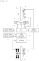
- the motor vehicle mainly includes a motor 1, an inverter 2, a mechanical brake (3a, 3b), a first power storage device 4, a second power storage device 5, an accelerator operation means 6, a mechanical brake operation means 7, a regenerative brake operation means 8, a power converter 10, an ECU 11, a start switch 12, and a monitor 13 (auxiliary device).
- the motor 1 includes an electromagnetic motor for obtaining a driving force by energy supply. As illustrated in Figs. 2 and 3 , the motor 1 can be electrically connected to the second power storage device 5, the power converter 10, and the first power storage device 4 via the inverter 2, and is capable of performing power driving and regeneration.
- the inverter 2 (DC-AC inverter) can convert a direct current into an alternating current. In this embodiment, the inverter 2 can convert a direct current of the first power storage device 4 and the second power storage device 5 into an alternating current and supply the alternating current to the motor 1.
- the mechanical brake includes a brake device capable of braking by releasing energy, such as a disc brake or a drum brake.
- the mechanical brake includes a driving-wheel mechanical brake 3a for braking by releasing kinetic energy of a driving wheel Ta and a driven-wheel mechanical brake 3b for braking by releasing kinetic energy of a driven wheel Tb.
- the driving-wheel mechanical brake 3a and the driven-wheel mechanical brake 3b are connected to the mechanical brake operation means 7 via a brake actuator 9.
- the regenerative brake operation means 8 includes a component capable of controlling the motor 1 to adjust a braking torque of the driving wheel Ta and recovering energy in the power storage device (first power storage device 4 and second power storage device 5) (in this embodiment, an operation lever attached to a left end portion of the handlebar).
- the regenerative brake operation means 8 is configured to cause the motor 1 to perform the regeneration in accordance with the operation amount to obtain a desired braking force. By the regeneration of the motor 1, energy can be recovered in the first power storage device 4 and the second power storage device 5.
- first switch S3 and the second switch S4 are configured by semiconductor switching elements (MOSFETs) 14 and 15 (including diodes as rectifiers as in the semiconductor switching elements 10a and 10b), and the third switch S5 is configured by a switch capable of switching on/off (connecting or disconnecting) the conduction of current.
- the first switch S3, the second switch S4, and the third switch S5 can be turned on/off (set to the connected state or the disconnected state) at a given timing under the control of a circuit control unit 17.
- the ECU 11 is for controlling the motor 1 and the like in accordance with a request input from a driver.
- the ECU 11 includes the inverter control unit 16, the circuit control unit 17, and the mechanical brake control unit 18, and is connected to the inverter 2, the power converter 10, the first power storage device 4, the second power storage device 5, and the brake actuator 9.
- the voltage detection sensor 4a is capable of detecting the voltage of the first power storage device 4
- the temperature detection sensor 4b is capable of detecting the temperature of the first power storage device 4
- the voltage detection sensor 5a is capable of detecting the voltage of the second power storage device 5.
- the motor vehicle according to this embodiment is also configured as follows. During the power driving of the motor 1, in a case where the power storage status of the second power storage device 5 is greater than or equal to a predetermined value (greater than or equal to the predetermined lower limit value in Fig. 26 ), the first switch S3 is set to the disconnected state, the second switch S4 is set to the connected state, and the third switch S5 is set to the disconnected state, and energy is supplied from the first power storage device 4 and the second power storage device 5 to the inverter 2 while the output voltage of the first power storage device 4 is stepped down.
- a predetermined value greater than or equal to the predetermined lower limit value in Fig. 26
- the first switch S3 is set to the disconnected state
- the second switch S4 is set to the disconnected state
- the third switch S5 is set to the connected state
- energy is supplied from the second power storage device 5 to the inverter 2.
- the temperature state of the first power storage device 4 can be determined by the temperature detection sensor 4b, based on the temperature of the first power storage device 4, and, during the power driving of the motor 1, in a case where the temperature of the first power storage device 4 is greater than or equal to a predetermined value, energy is supplied from the second power storage device 5 to the inverter 2 while energy supply from the first power storage device 4 is stopped.
- the start switch 12 includes an operation switch that allows the vehicle to travel. By operating the accelerator operation means 6 after the start switch 12 is operated, the motor 1 may be actuated for traveling.
- the monitor 13 includes an auxiliary device such as a liquid crystal monitor attached to the vehicle. For example, the monitor 13 may display conditions of the vehicle (speed, power storage status, or whether malfunction has occurred) or a map of a navigation system.
- this embodiment provides a detection means 19 including a sensor that detects the rotation speed of the motor 1.
- a predetermined braking torque in accordance with the operation amount of the regenerative brake operation means 8 is generated by regenerative braking (in particular, in this embodiment, the predetermined braking torque is generated only by the regenerative braking).
- the maximum value of the predetermined braking torque is a rated torque of the motor 1.
- Fig. 5 illustrates changes in parameters in a case where the accelerator operation means 6 and the regenerative brake operation means 8 are operated after the start switch 12 is turned on in the motor vehicle according to the above-described embodiment.
- charging is started and the second power storage device 5 is charged during the stopping of the motor 1 and during the power driving of the motor 1.
- FCCNO function circuit control number
- Fig. 9 The relationship between the braking torque at the driven wheel Tb and the vehicle speed has the characteristics as illustrated in Fig. 9
- Fig. 10 the relationship between the braking torque (mechanical braking torque (Tbmf)) at the driven wheel Tb and the rotation speed ( ⁇ ) of the motor 1 has the characteristics as illustrated in Fig. 10 . Since Figs. 9 and 10 illustrate the characteristics of the driven wheel Tb, only the characteristics (braking torque) on the negative side (lower half) of the vertical axis are illustrated.
- the process proceeds to S9, and a mechanical braking torque (Tbmr) in accordance with the operation amount of the regenerative brake operation means 8 is calculated based on Table 5 illustrated in Fig. 16 .
- the process proceeds to S13, and a mechanical braking torque (Tbmf) in accordance with the operation amount of the mechanical brake operation means 7 is calculated based on Table 6 illustrated in Fig. 17 .
- the mechanical braking torque (Tbmr) calculated in S9 is set as the braking torque of the driving wheel Ta
- the mechanical braking torque (Tbmf) calculated in S13 is set as the braking torque of the driven wheel Tb.
- the process proceeds to S6, and the motor torque (Tm) in accordance with the operation amount of the regenerative brake operation means 8 is calculated based on Table 2 illustrated in Fig. 13 .
- control of the motor vehicle according to this embodiment will be described based on the flowcharts in Figs. 18a and 18b .
- FCCNO 1
- Duty control is performed on the switches S1 and S2 of the semiconductor switching elements 10a and 10b during the power driving, the power converter 10 steps down the output voltage of the first power storage device 4, the first switch S3 is set to the connected state (on state), the second switch S4 is set to the disconnected state (off state), and the third switch S5 is set to the disconnected state (off state).
- FCCNO 1
- current control of the inverter 2 is performed based on Table A illustrated in Fig. 20 .
- FCCNO 3
- Duty control is performed on the switches S1 and S2 of the semiconductor switching elements 10a and 10b during the power driving and during charging, the power converter 10 steps down the output voltage of the first power storage device 4, the first switch S3 is set to the connected state (on state), the second switch S4 is set to the disconnected state (off state), and the third switch S5 is set to the connected state (on state).
- FCCNO 3
- the current control of the inverter 2 is performed based on Table C illustrated in Fig. 22 .
- the first switch S3 is set to the connected state
- the second switch S4 is set to the disconnected state
- the third switch S5 is set to the connected state
- energy is supplied from the first power storage device 4 to the second power storage device 5 while the output voltage (Vdc1) of the first power storage device 4 is stepped down.
- the second power storage device 5 can be charged. Accordingly, it is possible to suppress shortage of energy of the second power storage device 5 when the vehicle is traveling, while reducing the size of the second power storage device 5, and improve the life of the first power storage device 4.
- the motor vehicle it is possible to determine the power storage status of the second power storage device 5, based on the voltage of the second power storage device 5, and, in a case where the power storage status of the second power storage device 5 is less than or equal to the predetermined value, the energy is supplied to the second power storage device 5 while the output voltage of the first power storage device 4 is stepped down. Accordingly, the second power storage device 5 can be charged in accordance with the power storage status of the second power storage device 5.
- the first switch S3 is set to the disconnected state
- the second switch S4 is set to the connected state
- the third switch S5 is set to the disconnected state
- the first switch S3 is set to the disconnected state
- the second switch S4 is set to the connected state
- the third switch S5 is set to the disconnected state
- the energy is supplied from the first power storage device 4 and the second power storage device 5 to the inverter 2 while the output voltage of the first power storage device 4 is stepped down. Accordingly, the energy can be supplied from both the first power storage device 4 and the second power storage device 5 to the inverter 2, and the motor vehicle can travel.
- the first switch S3 is set to the disconnected state
- the second switch S4 is set to the disconnected state
- the third switch S5 is set to the connected state
- the energy is supplied from the second power storage device 5 to the inverter 2. Accordingly, the energy can be supplied from the second power storage device 5 while the first power storage device 4 is stopped, and the motor vehicle can travel.
- the power storage device includes the first power storage device 4 having a large-capacity characteristic and the second power storage device 5 having a high-power characteristic.
- the power storage device also includes a circuit in which the power converter 10 having the function of stepping down the voltage during the power driving is connected to the first power storage device 4 and in which the second power storage device 5 is connected in series between the reactor 10c of the power converter 10 and the inverter 2, and the energy is recovered in the first power storage device 4 and the second power storage device 5 using the circuit during the regeneration of the motor 1. Accordingly, during the regeneration of the motor 1, the rated torque can be generated only by the regenerative braking to a higher rotation than the motor rotation speed at which the rated torque can be generated only by the first power storage device 4.
- the output voltage of the first power storage device 4 is stepped down, and the energy is supplied from the first power storage device 4 and the second power storage device 5 to the inverter 2. Accordingly, the voltage can be stepped down and stepped up by using the stepping up function of the second power storage device 5 in combination. Therefore, since the output voltage of the first power storage device 4 can be stepped up and stepped down to be adjusted to match the direct current voltage setting of the inverter 2, a storage battery with a standard voltage can be used even when the direct current voltage setting value of the inverter 2 changes, and an increase in manufacturing cost can be prevented.
- the present invention is not limited thereto.
- the first switch S3, the second switch S4, and the third switch S5 may be switches of other forms, and a separately required switch may be added.
- the semiconductor switching element may be an IGBT instead of the MOSFET.
- the present invention may be applied to a vehicle not provided with the monitor 13, or a three-wheel vehicle or a four-wheel vehicle such as a buggy.
- the present invention can be applied to a motor vehicle having a different external shape or having other functions added thereto.
Landscapes
- Engineering & Computer Science (AREA)
- Power Engineering (AREA)
- Transportation (AREA)
- Mechanical Engineering (AREA)
- Life Sciences & Earth Sciences (AREA)
- Sustainable Development (AREA)
- Sustainable Energy (AREA)
- Physics & Mathematics (AREA)
- Electromagnetism (AREA)
- Electric Propulsion And Braking For Vehicles (AREA)
- Charge And Discharge Circuits For Batteries Or The Like (AREA)
- Dc-Dc Converters (AREA)
Abstract
Description
- The present invention relates to a motor vehicle including a motor capable of performing power driving and regeneration, and a power storage device capable of supplying energy to the motor.
- For example, PTL 1 describes a motor vehicle that includes a motor capable of performing power driving and regeneration and a power storage device capable of supplying energy to the motor, obtains a thrust by a driving force of the motor, and can recover energy in the power storage device by adjusting a braking torque of driving wheels. According to such a motor vehicle, energy can be supplied to an inverter at a given timing from each of a battery having a large-capacity characteristic and a capacitor having a high-power characteristic to drive the motor.
- PTL 1:
Japanese Unexamined Patent Application Publication No. 2018-166367 - However, in the above-described related art, although the battery (first power storage device) and the capacitor (second power storage device) can share energy supply to drive the motor, when charging by regeneration is not in time and energy of the capacitor is insufficient, it is necessary to supply energy only from the battery. Even so, since rapid energy supply is necessary at the time of acceleration of the vehicle, for example, when energy is supplied only from the battery, there is a possibility that the battery generates heat due to the rapid energy supply and the life of the battery is shortened. In addition, in order to prevent shortage of energy of the capacitor when the vehicle is traveling, it is conceivable to charge the capacitor with a large amount of energy by using a charger in advance, for example, when the vehicle is not in use. However, in this case, there is a problem in that the size of the capacitor is increased.
- The present invention has been made in view of such circumstances and provides a motor vehicle capable of suppressing shortage of energy of the second power storage device when the vehicle is traveling, while reducing the size of the second power storage device, and capable of improving the life of the first power storage device.
- An invention according to
claim 1 is a motor vehicle including: a motor capable of performing power driving; and an inverter capable of converting a direct current into an alternating current, the motor vehicle including: a first power storage device having a large-capacity characteristic; a second power storage device having a high-power characteristic; a power converter having a function of stepping down a voltage during the power driving; a circuit in which the power converter having the function of stepping down the voltage during the power driving is connected to the first power storage device and in which the second power storage device is connected in series between a reactor of the power converter and the inverter; a first switch that forms a circuit connecting the power converter and the inverter not via the second power storage device; a second switch that forms a circuit connecting the power converter and the inverter via the second power storage device; and a third switch that forms a circuit connecting the second power storage device and a ground, in which, during stopping of the motor and/or during the power driving of the motor, the first switch is set to a connected state, the second switch is set to a disconnected state, and the third switch is set to a connected state, and energy is supplied from the first power storage device to the second power storage device while an output voltage of the first power storage device is stepped down. - According to an invention according to
claim 2, in the motor vehicle according toclaim 1, it is possible to determine a power storage status of the second power storage device, based on a voltage of the second power storage device, and, in a case where the power storage status of the second power storage device is less than or equal to a predetermined value, the energy is supplied to the second power storage device while the output voltage of the first power storage device is stepped down. - According to an invention according to
claim 3, in the motor vehicle according toclaim - According to an invention according to
claim 4, in the motor vehicle according to any one ofclaims 1 to 3, during the power driving of the motor, the first switch is set to a disconnected state, the second switch is set to a connected state, and the third switch is set to a disconnected state, and the energy is supplied from the first power storage device and the second power storage device to the inverter while the output voltage of the first power storage device is stepped down. - According to an invention according to
claim 5, in the motor vehicle according to any one ofclaims 1 to 4, during the power driving of the motor, the first switch is set to a disconnected state, the second switch is set to a disconnected state, and the third switch is set to a connected state, and the energy is supplied from the second power storage device to the inverter. - According to an invention according to
claim 6, in the motor vehicle according toclaim 5, it is possible to determine a temperature state of the first power storage device, based on a temperature of the first power storage device, and, during the power driving of the motor, in a case where the temperature of the first power storage device is greater than or equal to a predetermined value, the energy is supplied from the second power storage device to the inverter. - According to an invention according to
claim 7, in the motor vehicle according to any one ofclaims 1 to 6, the first power storage device has a higher voltage characteristic than the second power storage device. - According to an invention according to
claim 8, in the motor vehicle according to any one ofclaims 1 to 7, an energy amount of the first power storage device when fully charged is larger than an energy amount of the second power storage device when fully charged. - According to an invention according to
claim 9, in the motor vehicle according to any one ofclaims 1 to 8, the first power storage device includes a replaceable cassette-type power storage device. - According to an invention according to
claim 10, in the motor vehicle according to any one ofclaims 1 to 9, the first power storage device includes a large-capacity lithium ion battery or a large-capacity nickel-metal hydride battery, and the second power storage device includes any one of a high-power lithium ion battery, a high-power nickel-metal hydride battery, a lithium ion capacitor, and an electric double layer capacitor. - According to the present invention, during the stopping of the motor and/or during the power driving of the motor, the first switch is set to the connected state, the second switch is set to the disconnected state, and the third switch is set to the connected state, and the energy is supplied from the first power storage device to the second power storage device while the output voltage of the first power storage device is stepped down. Accordingly, it is possible to suppress shortage of energy of the second power storage device when the vehicle is traveling, while reducing the size of the second power storage device, and improve the life of the first power storage device.
-
- [
Fig. 1] Fig. 1 is a schematic diagram illustrating a motor vehicle according to an embodiment of the present invention. - [
Fig. 2] Fig. 2 is a circuit diagram illustrating a power converter of the motor vehicle. - [
Fig. 3] Fig. 3 is a conceptual diagram illustrating the power converter of the motor vehicle. - [
Fig. 4] Fig. 4 is a schematic diagram illustrating a control relationship of the motor vehicle. - [
Fig. 5] Fig. 5 is a time chart illustrating power control of the motor vehicle. - [
Fig. 6] Fig. 6 is a flowchart illustrating the entirety of the power control of the motor vehicle. - [
Fig. 7] Fig. 7 is a graph illustrating request characteristics (vehicle request of a driving wheel) of the motor vehicle. - [
Fig. 8] Fig. 8 is a graph illustrating request characteristics (motor request of the driving wheel) of the motor vehicle. - [
Fig. 9] Fig. 9 is a graph illustrating request characteristics (vehicle request of a driven wheel) of the motor vehicle. - [
Fig. 10] Fig. 10 is a graph illustrating request characteristics (brake request of the driven wheel) of the motor vehicle. - [
Fig. 11] Fig. 11 is a flowchart illustrating request process control of the power control of the motor vehicle. - [
Fig. 12] Fig. 12 is a graph illustrating a driver request table (Table 1) of the motor vehicle. - [
Fig. 13] Fig. 13 is a graph illustrating a driver request table (Table 2) of the motor vehicle. - [
Fig. 14] Fig. 14 is a graph illustrating a driver request table (Table 3) of the motor vehicle. - [
Fig. 15] Fig. 15 is a graph illustrating a driver request table (Table 4) of the motor vehicle. - [
Fig. 16] Fig. 16 is a graph illustrating a driver request table (Table 5) of the motor vehicle. - [
Fig. 17] Fig. 17 is a graph illustrating a driver request table (Table 6) of the motor vehicle. - [
Fig. 18a] Fig. 18a is a flowchart illustrating motor control of the power control of the motor vehicle. - [
Fig. 18b] Fig. 18b is a flowchart illustrating the motor control of the power control of the motor vehicle. - [
Fig. 19] Fig. 19 is a table illustrating power conversion circuit control of the motor vehicle. - [
Fig. 20] Fig. 20 is a graph illustrating a voltage request table (Table A) of the motor vehicle. - [
Fig. 21] Fig. 21 is a graph illustrating a voltage request table (Table B) of the motor vehicle. - [
Fig. 22] Fig. 22 is a graph illustrating a voltage request table (Table C) of the motor vehicle. - [
Fig. 23] Fig. 23 is a graph illustrating a voltage request table (Table D) of the motor vehicle. - [
Fig. 24] Fig. 24 is a graph illustrating a voltage request table (Table E) of the motor vehicle. - [
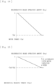
Fig. 25] Fig. 25 is a graph illustrating a power storage status of a first power storage device of the motor vehicle. - [
Fig. 26] Fig. 26 is a graph illustrating a power storage status of a second power storage device of the motor vehicle. - [
Fig. 27] Fig. 27 is a table illustrating combinations of the power storage devices of the motor vehicle. - Hereinafter, an embodiment of the present invention will be described in detail with reference to the drawings.
- A motor vehicle according to this embodiment includes a saddle-type vehicle such as a motorcycle that can travel by a driving force of a motor. As illustrated in
Figs. 1 to 4 , the motor vehicle mainly includes amotor 1, aninverter 2, a mechanical brake (3a, 3b), a firstpower storage device 4, a secondpower storage device 5, an accelerator operation means 6, a mechanical brake operation means 7, a regenerative brake operation means 8, apower converter 10, anECU 11, astart switch 12, and a monitor 13 (auxiliary device). - The motor 1 (Motor) includes an electromagnetic motor for obtaining a driving force by energy supply. As illustrated in
Figs. 2 and3 , themotor 1 can be electrically connected to the secondpower storage device 5, thepower converter 10, and the firstpower storage device 4 via theinverter 2, and is capable of performing power driving and regeneration. The inverter 2 (DC-AC inverter) can convert a direct current into an alternating current. In this embodiment, theinverter 2 can convert a direct current of the firstpower storage device 4 and the secondpower storage device 5 into an alternating current and supply the alternating current to themotor 1. - The mechanical brake includes a brake device capable of braking by releasing energy, such as a disc brake or a drum brake. The mechanical brake includes a driving-wheel
mechanical brake 3a for braking by releasing kinetic energy of a driving wheel Ta and a driven-wheelmechanical brake 3b for braking by releasing kinetic energy of a driven wheel Tb. The driving-wheelmechanical brake 3a and the driven-wheelmechanical brake 3b are connected to the mechanical brake operation means 7 via abrake actuator 9. - The mechanical brake operation means 7 includes a component capable of controlling the mechanical brake (driven-wheel
mechanical brake 3b) to adjust a braking torque (in this embodiment, an operation lever attached to a right end portion of a handlebar). The mechanical brake operation means 7 is configured such that a mechanical brake control unit 18 (seeFig. 4 ) can actuate thebrake actuator 9 in accordance with the operation amount to operate the driven-wheelmechanical brake 3b. - The accelerator operation means 6 includes a component capable of controlling the
motor 1 to adjust a driving torque of the driving wheel Ta (in this embodiment, an accelerator grip attached to a right end portion of the handlebar). As illustrated inFig. 4 , the accelerator operation means 6 is configured to estimate a torque request by using aninverter control unit 16 in accordance with the operation amount and actuates themotor 1 to obtain a desired driving force. Note that theinverter control unit 16 is one of control units formed in theECU 11. - A power storage device is capable of supplying energy to the
motor 1. In this embodiment, the power storage device includes the firstpower storage device 4 and the secondpower storage device 5. The firstpower storage device 4 includes a storage battery having a large-capacity characteristic. As illustrated inFig. 27 , for example, a large-capacity lithium ion battery or a large-capacity nickel-metal hydride battery can be used for the firstpower storage device 4. The secondpower storage device 5 includes a storage battery having a high-power characteristic. As illustrated inFig. 27 , for example, any one of high-power lithium ion battery, a high-power nickel-metal hydride battery, a lithium ion capacitor, and an electric double layer capacitor can be used for the secondpower storage device 5. - More specifically, the first
power storage device 4 has a higher voltage characteristic than the secondpower storage device 5, and in addition, an energy amount of the firstpower storage device 4 when fully charged is larger than an energy amount of the secondpower storage device 5 when fully charged. In addition, the firstpower storage device 4 according to this embodiment includes a replaceable cassette-type power storage device that can be removed from the vehicle. In accordance with a power storage status of the firstpower storage device 4, the firstpower storage device 4 can be replaced with a firstpower storage device 4 in a fully charged state. - The regenerative brake operation means 8 includes a component capable of controlling the
motor 1 to adjust a braking torque of the driving wheel Ta and recovering energy in the power storage device (firstpower storage device 4 and second power storage device 5) (in this embodiment, an operation lever attached to a left end portion of the handlebar). The regenerative brake operation means 8 is configured to cause themotor 1 to perform the regeneration in accordance with the operation amount to obtain a desired braking force. By the regeneration of themotor 1, energy can be recovered in the firstpower storage device 4 and the secondpower storage device 5. - The
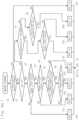
power converter 10 has a function of stepping down the voltage during the power driving of the motor 1 (when energy is supplied to the motor 1) and a function of stepping up the voltage during the regeneration of the motor 1 (when energy is recovered from the motor 1). As illustrated inFigs. 2 and3 , thepower converter 10 is connected between the firstpower storage device 4 and the secondpower storage device 5 in an electric circuit. More specifically, as illustrated inFig. 2 , thepower converter 10 includes two semiconductor switching elements (MOSFETs) 10a and 10b and areactor 10c (coil). The two semiconductor switching elements (MOSFETs) 10a and 10b include switches S1 and S2 and diodes as rectifiers. - According to the
power converter 10 according to this embodiment, by rapidly switching (performing duty control of) the switches S1 and S2 of thesemiconductor switching elements reactor 10c is positioned downstream of thesemiconductor switching elements Fig. 3 ), and the voltage can be stepped up because thereactor 10c is positioned upstream of thesemiconductor switching elements Fig. 3 ). - More specifically, as illustrated in
Figs. 2 and3 , this embodiment provides a circuit in which thepower converter 10 having a function of stepping down the voltage during the power driving is connected to the firstpower storage device 4 and in which the secondpower storage device 5 is connected in series between thereactor 10c of thepower converter 10 and theinverter 2. Thus, during the power driving of themotor 1, thepower converter 10 steps down an output voltage (Vdc1) of the firstpower storage device 4 to supply energy from the firstpower storage device 4 and the secondpower storage device 5 to theinverter 2, and in addition, during the regeneration of themotor 1, thepower converter 10 steps up an output voltage (Vinv - Vdc2) of the secondpower storage device 5 to recover energy in the firstpower storage device 4 and the secondpower storage device 5. - This embodiment also provides a first switch S3, a second switch S4, and a third switch S5. As illustrated in
Fig. 2 , the first switch S3 forms a circuit connecting thepower converter 10 and theinverter 2 not via the secondpower storage device 5, the second switch S4 forms a circuit connecting thepower converter 10 and theinverter 2 via the secondpower storage device 5, and the third switch S5 forms a circuit connecting the secondpower storage device 5 and the ground (ground connection). Note that capacitors Ca and Cb for stabilization are connected to the circuit according to this embodiment. - Furthermore, the first switch S3 and the second switch S4 according to this embodiment are configured by semiconductor switching elements (MOSFETs) 14 and 15 (including diodes as rectifiers as in the
semiconductor switching elements circuit control unit 17. - The
ECU 11 is for controlling themotor 1 and the like in accordance with a request input from a driver. As illustrated inFig. 4 , theECU 11 includes theinverter control unit 16, thecircuit control unit 17, and the mechanicalbrake control unit 18, and is connected to theinverter 2, thepower converter 10, the firstpower storage device 4, the secondpower storage device 5, and thebrake actuator 9. There are also provided avoltage detection sensor 4a and atemperature detection sensor 4b and also avoltage detection sensor 5a. Thevoltage detection sensor 4a is capable of detecting the voltage of the firstpower storage device 4, thetemperature detection sensor 4b is capable of detecting the temperature of the firstpower storage device 4, and thevoltage detection sensor 5a is capable of detecting the voltage of the secondpower storage device 5. - However, the
voltage detection sensor 4a, thetemperature detection sensor 4b, and thevoltage detection sensor 5a are electrically connected to thecircuit control unit 17. Thus, the power storage statuses of the firstpower storage device 4 and the secondpower storage device 5 can be determined based on the voltages detected by thevoltage detection sensor 4a and thevoltage detection sensor 5a, and the temperature of the firstpower storage device 4 can be detected by thetemperature detection sensor 4b. Note that the power storage status of the firstpower storage device 4 is illustrated inFig. 25 , and the power storage status of the secondpower storage device 5 is illustrated inFig. 26 . - During the power driving of the
motor 1, in a case where the power storage status of the secondpower storage device 5 is less than or equal to a charging determination value (less than or equal to the charging determination value inFig. 26 ), the first switch S3 is set to the connected state (ON state), the second switch S4 is set to the disconnected state (OFF state), and the third switch S5 is set to the connected state (ON state), and energy is supplied from the firstpower storage device 4 to theinverter 2 and the secondpower storage device 5 while the output voltage (Vdc1) of the firstpower storage device 4 is stepped down. - That is, during the power driving of the
motor 1, by setting the first switch S3 to the connected state (ON state), the second switch S4 to the disconnected state (OFF state), and the third switch S5 to the connected state (ON state), energy is supplied from the firstpower storage device 4 to theinverter 2 and also to the secondpower storage device 5 so that the secondpower storage device 5 can be charged. Similarly, during stopping of themotor 1, by setting the first switch S3 to the connected state (ON state), the second switch S4 to the disconnected state (OFF state), and the third switch S5 to the connected state (ON state), energy is supplied from the firstpower storage device 4 to the secondpower storage device 5 while the output voltage (Vdc1) of the firstpower storage device 4 is stepped down. - In this manner, in the motor vehicle according to the present embodiment, during the stopping of the
motor 1 and/or during the power driving of themotor 1, the first switch S3 is set to the connected state, the second switch S4 is set to the disconnected state, and the third switch S5 is set to the connected state, and energy is supplied from the firstpower storage device 4 to the secondpower storage device 5 so that the secondpower storage device 5 can be charged while the output voltage of the firstpower storage device 4 is stepped down. Furthermore, in the motor vehicle according to this embodiment, during the regeneration of themotor 1, the first switch S3 is set to the disconnected state, the second switch S4 is set to the connected state, and the third switch S5 is set to the disconnected state, and energy can be recovered (regenerative energy can be accumulated) in the firstpower storage device 4 and the secondpower storage device 5 while the output voltage (Vinv - Vdc2) of the secondpower storage device 5 is stepped up. - The motor vehicle according to this embodiment is also configured as follows. During the power driving of the
motor 1, in a case where the power storage status of the secondpower storage device 5 is greater than or equal to a predetermined value (greater than or equal to the predetermined lower limit value inFig. 26 ), the first switch S3 is set to the disconnected state, the second switch S4 is set to the connected state, and the third switch S5 is set to the disconnected state, and energy is supplied from the firstpower storage device 4 and the secondpower storage device 5 to theinverter 2 while the output voltage of the firstpower storage device 4 is stepped down. - Furthermore, during the power driving of the
motor 1, the first switch S3 is set to the disconnected state, the second switch S4 is set to the disconnected state, and the third switch S5 is set to the connected state, and energy is supplied from the secondpower storage device 5 to theinverter 2. Specifically, the temperature state of the firstpower storage device 4 can be determined by thetemperature detection sensor 4b, based on the temperature of the firstpower storage device 4, and, during the power driving of themotor 1, in a case where the temperature of the firstpower storage device 4 is greater than or equal to a predetermined value, energy is supplied from the secondpower storage device 5 to theinverter 2 while energy supply from the firstpower storage device 4 is stopped. - The
start switch 12 includes an operation switch that allows the vehicle to travel. By operating the accelerator operation means 6 after thestart switch 12 is operated, themotor 1 may be actuated for traveling. Themonitor 13 includes an auxiliary device such as a liquid crystal monitor attached to the vehicle. For example, themonitor 13 may display conditions of the vehicle (speed, power storage status, or whether malfunction has occurred) or a map of a navigation system. - Here, as illustrated in
Fig. 4 , this embodiment provides a detection means 19 including a sensor that detects the rotation speed of themotor 1. When the rotation speed of themotor 1 detected by the detection means 19 is greater than or equal to a predetermined value, a predetermined braking torque in accordance with the operation amount of the regenerative brake operation means 8 is generated by regenerative braking (in particular, in this embodiment, the predetermined braking torque is generated only by the regenerative braking). In addition, during the regeneration of themotor 1, the maximum value of the predetermined braking torque is a rated torque of themotor 1. - Furthermore, when the rotation speed of the
motor 1 detected by the detection means 19 is less than the predetermined value, the braking torque is generated by the mechanical brake (driving-wheelmechanical brake 3a) in accordance with the operation amount of the regenerative brake operation means 8. In addition, when a charge level of the firstpower storage device 4 is greater than or equal to a predetermined value, the braking torque is generated by the mechanical brake (driving-wheelmechanical brake 3a) in accordance with the operation amount of the regenerative brake operation means 8. -
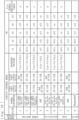
Fig. 5 illustrates changes in parameters in a case where the accelerator operation means 6 and the regenerative brake operation means 8 are operated after thestart switch 12 is turned on in the motor vehicle according to the above-described embodiment. In this embodiment, after thestart switch 12 is turned on, charging is started and the secondpower storage device 5 is charged during the stopping of themotor 1 and during the power driving of themotor 1. Note that "FCCNO" (function circuit control number) in the table inFig. 5 corresponds to "FCCNO" illustrated inFigs. 4 ,18b , and19 . - Next, control (main control) of the motor vehicle according to this embodiment will be described with reference to the flowchart in
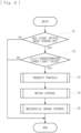
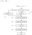
Fig. 6 . - First, it is determined in S1 whether the
start switch 12 has been turned on. If it is determined that thestart switch 12 has been turned on, it is determined in S2 whether the power storage status (Soc1) of the firstpower storage device 4 is greater than a predetermined lower limit value (seeFig. 25 ). If it is determined that the power storage status (Soc1) is greater than the predetermined lower limit value, a request process (S3), motor control (S4), and mechanical brake control (S5) are sequentially performed. - Next, request characteristics of the motor vehicle according to this embodiment will be described with reference to
Figs. 7 to 10 . - The relationship between each of the driving torque and the braking torque at the driving wheel Ta and a vehicle speed has characteristics as illustrated in
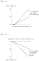
Fig. 7 , and the relationship between a motor torque at the driving wheel Ta and the rotation speed (ω) of themotor 1 has characteristics as illustrated inFig. 8 . In particular, inFig. 7 , in a case of high-speed traveling, the driving torque gradually decreases relative to the vehicle speed, whereas the braking torque is constant. InFig. 8 , the positive side (upper half) of the vertical axis indicates the driving torque in accordance with the operation amount of the accelerator operation means 6, and the negative side (lower half) of the vertical axis indicates the braking torque in accordance with the operation amount of the regenerative brake operation means 8. A reference sign Tml inFig. 8 indicates the rated torque of themotor 1. - The relationship between the braking torque at the driven wheel Tb and the vehicle speed has the characteristics as illustrated in
Fig. 9 , and the relationship between the braking torque (mechanical braking torque (Tbmf)) at the driven wheel Tb and the rotation speed (ω) of themotor 1 has the characteristics as illustrated inFig. 10 . SinceFigs. 9 and 10 illustrate the characteristics of the driven wheel Tb, only the characteristics (braking torque) on the negative side (lower half) of the vertical axis are illustrated. - Next, control (request process control) of the motor vehicle according to this embodiment will be described with reference to on the flowchart in
Fig. 11 . - First, it is determined in S1 whether a regeneration system is normal based on the presence or absence of a malfunction signal. If it is determined that there is no malfunction signal, it is determined in S2 whether the accelerator operation means 6 is operated (whether an accelerator operation amount Ap is greater than 0). If it is determined that the accelerator operation means 6 is operated, the process proceeds to S5, and a motor torque (Tm) in accordance with the operation amount of the accelerator operation means 6 is calculated based on Table 1 illustrated in
Fig. 12 . - After the calculation in S5, the process proceeds to S9, and a mechanical braking torque (Tbmr) in accordance with the operation amount of the regenerative brake operation means 8 is calculated based on Table 5 illustrated in
Fig. 16 . Subsequently, the process proceeds to S13, and a mechanical braking torque (Tbmf) in accordance with the operation amount of the mechanical brake operation means 7 is calculated based on Table 6 illustrated inFig. 17 . Note that the mechanical braking torque (Tbmr) calculated in S9 is set as the braking torque of the driving wheel Ta, and the mechanical braking torque (Tbmf) calculated in S13 is set as the braking torque of the driven wheel Tb. - If it is determined in S2 that the accelerator operation means 6 is not operated, it is determined in S3 whether the regeneration of the
motor 1 is possible. In this determination, in a case where the power storage status (Soc1) of the firstpower storage device 4 is less than or equal to a predetermined upper limit value (seeFig. 25 ) and the rotation speed of themotor 1 is greater than or equal to ω1 (seeFig. 8 ), it is determined that the regeneration of themotor 1 is possible. If it is determined that the regeneration of themotor 1 is possible, it is determined in S4 whether the power storage status (Soc2) of the secondpower storage device 5 is greater than a predetermined upper limit value (seeFig. 26 ). - If it is determined in S4 that the power storage status (Soc2) of the second
power storage device 5 is greater than the predetermined upper limit value (seeFig. 26 ), the process proceeds to S6, and the motor torque (Tm) in accordance with the operation amount of the regenerative brake operation means 8 is calculated based on Table 2 illustrated inFig. 13 . Here, in the calculation of the motor torque (Tm) based on Table 2, in a case where the rotation speed of themotor 1 is less than or equal to a predetermined rotation speed (ω2) illustrated inFig. 8 , correction of Tm = Tm(ω - ω1)/(ω2 - ω1) is performed. After the calculation in S6, the process proceeds to S10, and the mechanical braking torque (Tbmr) in accordance with the operation amount of the regenerative brake operation means 8 is calculated based on Table 4 illustrated inFig. 15 . Subsequently, the above-described S13 is sequentially performed. - If it is determined in S4 that the power storage status (Soc2) of the second
power storage device 5 is not greater than the predetermined upper limit value (seeFig. 26 ), the process proceeds to S7, and the motor torque (Tm) in accordance with the operation amount of the regenerative brake operation means 8 is calculated based on Table 3 illustrated inFig. 14 . Here, in the calculation of the motor torque (Tm) based on Table 3, as in the case of Table 2, in a case where the rotation speed of themotor 1 is less than or equal to the predetermined rotation speed (ω2) illustrated inFig. 8 , correction of Tm = Tm(ω - ω1)/(ω2 - ω1) is performed. After the calculation in S7, the mechanical braking torque (Tbmr) is set to 0 in S11. Subsequently, the above-described S13 is performed. - On the other hand, if it is determined in S1 that there is a malfunction signal or if it is determined in S3 that the regeneration is not possible, the process proceeds to S8, and the motor torque (Tm) is set to 0. Subsequently, the process proceeds to S12, and the mechanical braking torque (Tbmr) in accordance with the operation amount of the regenerative brake operation means 8 is calculated based on Table 5 illustrated in
Fig. 16 . Thus, if it is determined that malfunction has occurred in the regeneration system or if it is determined that the regeneration is not possible, the braking torque can be generated by the mechanical brake (driving-wheelmechanical brake 3a) in accordance with the operation amount of the regenerative brake operation means 8. After the calculation in S12, the above-described S13 is performed. - Next, control (motor control) of the motor vehicle according to this embodiment will be described based on the flowcharts in
Figs. 18a and18b . - First, it is determined in S1 whether the regeneration system is normal based on the presence or absence of a malfunction signal. If it is determined that there is no malfunction signal, it is determined in S2 whether the accelerator operation means 6 is operated (whether the accelerator operation amount Ap is greater than 0). If it is determined that the accelerator operation means 6 is operated, it is determined in S3 whether the power storage status (Soc2) of the second
power storage device 5 is greater than the predetermined lower limit value (seeFig. 26 ). - If it is determined in S3 that the power storage status (Soc2) of the second
power storage device 5 is not greater than the predetermined lower limit value (seeFig. 26 ), the process proceeds to S10, and FCC (function circuit control) is set to 1. If it is determined in S3 that the power storage status (Soc2) of the secondpower storage device 5 is greater than the predetermined lower limit value (seeFig. 26 ), the process proceeds to S4, and it is determined whether the rotation speed (ω) of themotor 1 is less than ω3. - If it is determined in S4 that the rotation speed (ω) of the
motor 1 is not less than ω3, the process proceeds to S11, and FCC is set to 2. If it is determined in S4 that the rotation speed (ω) of themotor 1 is less than ω3, the process proceeds to S5, and it is determined whether the temperature of the firstpower storage device 4 is less than the predetermined value. If it is determined in S5 that the temperature of the firstpower storage device 4 is not less than the predetermined value, the process proceeds to S13, and FCC is set to 4. If it is determined in S5 that the temperature of the firstpower storage device 4 is less than the predetermined value, the process proceeds to S6, and it is determined whether the accelerator operation amount Ap is less than a predetermined value. - Subsequently, if it is determined in S6 that the accelerator operation amount Ap is not less than the predetermined value, the process proceeds to S11, and FCC is set to 2. If it is determined in S6 that the accelerator operation amount Ap is less than the predetermined value, the process proceeds to S12, and FCC is set to 3. On the other hand, if it is determined in S2 that the accelerator operation means 6 is not operated, the process proceeds to S7, and it is determined whether the regeneration of the
motor 1 is possible. If it is determined that the regeneration is possible, the process proceeds to S8, and it is determined whether the power storage status (Soc2) of the secondpower storage device 5 is greater than the predetermined upper limit value. - If it is determined in S8 that the power storage status (Soc2) of the second
power storage device 5 is greater than the predetermined upper limit value, the process proceeds to S14, and FCC is set to 5. If it is determined in S8 that the power storage status (Soc2) of the secondpower storage device 5 is not greater than the predetermined upper limit value, the process proceeds to S15, and FCC is set to 6. If it is determined in S7 that the regeneration of themotor 1 is not possible, the process proceeds to S9, and it is determined whether the power storage status (Soc2) of the secondpower storage device 5 is less than or equal to the charging determination value. - If it is determined in S9 that the power storage status (Soc2) of the second
power storage device 5 is less than or equal to the charging determination value, the process proceeds to S16, and FCC is set to 7. If it is determined in S9 that the power storage status (Soc2) of the secondpower storage device 5 is greater than the charging determination value, the process proceeds to S17, and FCC is set to 8. Also, if it is determined in S1 that there is a malfunction signal, the process proceeds to S17, and FCC is set to 8. - After the modes (FCC) 1 to 8 are determined as described above, it is determined in S18 whether the mode (FCC) determined in the current process is changed from a mode (FCCO) determined in the previous process. If it is determined that the mode is not changed, the process proceeds to S19, and FCC determined in S10 to 17 is maintained. If it is determined that the mode is changed, the process proceeds to S20, and FCCNO is set to 8. Subsequently, in S21, circuit control in accordance with FCCNO is performed, and in S22, charging control in accordance with FCCNO is performed. Subsequently, in S23, the mode (FCC) determined at the current process is stored as FCCO, and in S24, inverter control is performed.
- Here, the control in S21 is performed based on the control table in
Fig. 19 . Details of the control based on the control table will be described below. - If FCCNO = 1, Duty control is performed on the switches S1 and S2 of the
semiconductor switching elements power converter 10 steps down the output voltage of the firstpower storage device 4, the first switch S3 is set to the connected state (on state), the second switch S4 is set to the disconnected state (off state), and the third switch S5 is set to the disconnected state (off state). In addition, if FCCNO = 1, current control of theinverter 2 is performed based on Table A illustrated inFig. 20 . - According to Table A, on the assumption that the current control of the
inverter 2 is performed by PWM control (pulse width modulation), as illustrated inFig. 20 , the direct current voltage of theinverter 2 can be controlled in accordance with the rotation speed (ω) of themotor 1. As for Tables B to E to be described later, it is also assumed that the current control of theinverter 2 is performed by PWM control. - If FCCNO = 2, Duty control is performed on the switches S1 and S2 of the
semiconductor switching elements power converter 10 steps down the output voltage of the firstpower storage device 4, the first switch S3 is set to the disconnected state (off state), the second switch S4 is set to the connected state (on state), and the third switch S5 is set to the disconnected state (off state). In addition, if FCCNO = 2, the current control of theinverter 2 is performed based on Table B illustrated inFig. 21 . - If FCCNO = 3, Duty control is performed on the switches S1 and S2 of the
semiconductor switching elements power converter 10 steps down the output voltage of the firstpower storage device 4, the first switch S3 is set to the connected state (on state), the second switch S4 is set to the disconnected state (off state), and the third switch S5 is set to the connected state (on state). In addition, if FCCNO = 3, the current control of theinverter 2 is performed based on Table C illustrated inFig. 22 . - If FCCNO = 4, the switches S1 and S2 of the
semiconductor switching elements power converter 10 is set to the off state), the first switch S3 and the second switch S4 are set to the disconnected state (off state), and the third switch S5 is set to the connected state (on state). In addition, if FCCNO = 4, the current control of theinverter 2 is performed based on Table C illustrated inFig. 22 . - If FCCNO = 5, Duty control is performed on the switches S1 and S2 of the
semiconductor switching elements inverter 2 is performed based on Table D illustrated inFig. 23 . - If FCCNO = 6, Duty control is performed on the switches S1 and S2 of the
semiconductor switching elements inverter 2 is performed based on Table E illustrated inFig. 24 . - If FCCNO = 7, Duty control is performed on the switches S1 and S2 of the
semiconductor switching elements inverter 2 is performed based on Table C illustrated inFig. 22 . - If FCCNO = 8, the switches S1 and S2 of the
semiconductor switching elements power converter 10 is set to the off state), the first switch S3, the second switch S4, and the third switch S5 are set to the off state. If FCCNO = 9, Duty control is performed on the switches S1 and S2 of thesemiconductor switching elements - According to the motor vehicle according to the above-described embodiment, during the stopping of the
motor 1 and/or during the power driving of themotor 1, the first switch S3 is set to the connected state, the second switch S4 is set to the disconnected state, and the third switch S5 is set to the connected state, and energy is supplied from the firstpower storage device 4 to the secondpower storage device 5 while the output voltage (Vdc1) of the firstpower storage device 4 is stepped down. Thus, during the stopping of themotor 1 and/or during the power driving of themotor 1, the secondpower storage device 5 can be charged. Accordingly, it is possible to suppress shortage of energy of the secondpower storage device 5 when the vehicle is traveling, while reducing the size of the secondpower storage device 5, and improve the life of the firstpower storage device 4. - In particular, in the motor vehicle according to this embodiment, it is possible to determine the power storage status of the second
power storage device 5, based on the voltage of the secondpower storage device 5, and, in a case where the power storage status of the secondpower storage device 5 is less than or equal to the predetermined value, the energy is supplied to the secondpower storage device 5 while the output voltage of the firstpower storage device 4 is stepped down. Accordingly, the secondpower storage device 5 can be charged in accordance with the power storage status of the secondpower storage device 5. In addition, during the regeneration of themotor 1, the first switch S3 is set to the disconnected state, the second switch S4 is set to the connected state, and the third switch S5 is set to the disconnected state, and the energy (regenerative energy) is recovered in the firstpower storage device 4 and the secondpower storage device 5. Accordingly, the regenerative energy can be efficiently recovered. - Furthermore, during the power driving of the
motor 1, the first switch S3 is set to the disconnected state, the second switch S4 is set to the connected state, and the third switch S5 is set to the disconnected state, and the energy is supplied from the firstpower storage device 4 and the secondpower storage device 5 to theinverter 2 while the output voltage of the firstpower storage device 4 is stepped down. Accordingly, the energy can be supplied from both the firstpower storage device 4 and the secondpower storage device 5 to theinverter 2, and the motor vehicle can travel. - Furthermore, during the power driving of the
motor 1, the first switch S3 is set to the disconnected state, the second switch S4 is set to the disconnected state, and the third switch S5 is set to the connected state, and the energy is supplied from the secondpower storage device 5 to theinverter 2. Accordingly, the energy can be supplied from the secondpower storage device 5 while the firstpower storage device 4 is stopped, and the motor vehicle can travel. In particular, it is possible to determine the temperature state of the firstpower storage device 4, based on the temperature of the firstpower storage device 4, and, during the power driving of themotor 1, in a case where the temperature of the firstpower storage device 4 is greater than or equal to the predetermined value, the energy is supplied from the secondpower storage device 5 to theinverter 2. Accordingly, the energy can be supplied from the secondpower storage device 5 while avoiding overheating of the firstpower storage device 4, and the motor vehicle can travel. - In addition, the power storage device includes the first
power storage device 4 having a large-capacity characteristic and the secondpower storage device 5 having a high-power characteristic. The power storage device also includes a circuit in which thepower converter 10 having the function of stepping down the voltage during the power driving is connected to the firstpower storage device 4 and in which the secondpower storage device 5 is connected in series between thereactor 10c of thepower converter 10 and theinverter 2, and the energy is recovered in the firstpower storage device 4 and the secondpower storage device 5 using the circuit during the regeneration of themotor 1. Accordingly, during the regeneration of themotor 1, the rated torque can be generated only by the regenerative braking to a higher rotation than the motor rotation speed at which the rated torque can be generated only by the firstpower storage device 4. - Furthermore, during the power driving of the motor, the output voltage of the first
power storage device 4 is stepped down, and the energy is supplied from the firstpower storage device 4 and the secondpower storage device 5 to theinverter 2. Accordingly, the voltage can be stepped down and stepped up by using the stepping up function of the secondpower storage device 5 in combination. Therefore, since the output voltage of the firstpower storage device 4 can be stepped up and stepped down to be adjusted to match the direct current voltage setting of theinverter 2, a storage battery with a standard voltage can be used even when the direct current voltage setting value of theinverter 2 changes, and an increase in manufacturing cost can be prevented. - In particular, according to this embodiment, during the power driving, duty control is performed on the switches S1 and S2 of the
semiconductor switching elements power converter 10. Accordingly, stepping up/down control of the inverter direct current voltage of themotor 1 with respect to the voltage of the firstpower storage device 4 can be optimally performed. In addition, since the firstpower storage device 4 and the secondpower storage device 5 share energy supply for the power driving, the current of the firstpower storage device 4 is reduced as compared with the case where only the firstpower storage device 4 supplies the same amount of energy for the power driving. Thus, even in a case where the energy for the power driving is large, the current of the firstpower storage device 4 can be reduced, and the life of the firstpower storage device 4 can be improved. - However, since the first
power storage device 4 has a higher voltage characteristic than the secondpower storage device 5, the output voltage of the firstpower storage device 4 can be stepped down to supply the energy to the secondpower storage device 5. In addition, the energy amount of the firstpower storage device 4 when fully charged is greater than the energy amount of the secondpower storage device 5 when fully charged. Accordingly, the energy can be smoothly supplied from the firstpower storage device 4 to the secondpower storage device 5. Furthermore, since the firstpower storage device 4 includes a replaceable cassette-type power storage device, the firstpower storage device 4 can be replaced in a short time when necessary, and the energy can be stably supplied from the firstpower storage device 4 to the secondpower storage device 5. - Although this embodiment has been described above, the present invention is not limited thereto. For example, the first switch S3, the second switch S4, and the third switch S5 may be switches of other forms, and a separately required switch may be added. In addition, the semiconductor switching element may be an IGBT instead of the MOSFET. Furthermore, the present invention may be applied to a vehicle not provided with the
monitor 13, or a three-wheel vehicle or a four-wheel vehicle such as a buggy. - As long as the motor vehicle is a motor vehicle in which, during the stopping of the motor and/or during the power driving of the motor, the first switch is set to the connected state, the second switch is set to the disconnected state, and the third switch is set to the connected state, and the energy is supplied from the first power storage device to the second power storage device while the output voltage of the first power storage device is stepped down, the present invention can be applied to a motor vehicle having a different external shape or having other functions added thereto.
-
- 1
- motor
- 2
- inverter
- 3a
- driving-wheel mechanical brake
- 3b
- driven-wheel mechanical brake
- 4
- first power storage device
- 4a
- voltage detection sensor
- 4b
- temperature detection sensor
- 5
- second power storage device
- 5a
- voltage detection sensor
- 6
- accelerator operation means
- 7
- mechanical brake operation means
- 8
- regenerative brake operation means
- 9
- brake actuator
- 10
- power converter
- 10a, 10b
- semiconductor switching element (MOSFET)
- 10c
- reactor (coil)
- 11
- ECU
- 12
- start switch
- 13
- monitor (auxiliary device)
- 14, 15
- semiconductor switching element (MOSFET)
- 16
- inverter control unit
- 17
- circuit control unit
- 18
- mechanical brake control unit
- 19
- detection means
- Ta
- driving wheel
- Tb
- driven wheel
- S3
- first switch
- S4
- second switch
- S5
- third switch
- Ca
- smoothing capacitor
- Cb
- smoothing capacitor
- Vdc1
- first power storage device (battery) voltage
- Vdc2
- second power storage device (capacitor) voltage
- Vinv
- inverter direct current voltage
- V1
- S2 terminal average voltage
Claims (10)
- A motor vehicle comprising:a motor capable of performing power driving; andan inverter capable of converting a direct current into an alternating current, the motor vehicle comprising:a first power storage device having a large-capacity characteristic;a second power storage device having a high-power characteristic;a power converter having a function of stepping down a voltage during the power driving;a circuit in which the power converter having the function of stepping down the voltage during the power driving is connected to the first power storage device and in which the second power storage device is connected in series between a reactor of the power converter and the inverter;a first switch that forms a circuit connecting the power converter and the inverter not via the second power storage device;a second switch that forms a circuit connecting the power converter and the inverter via the second power storage device; anda third switch that forms a circuit connecting the second power storage device and a ground, whereinduring stopping of the motor and/or during the power driving of the motor, the first switch is set to a connected state, the second switch is set to a disconnected state, and the third switch is set to a connected state, and energy is supplied from the first power storage device to the second power storage device while an output voltage of the first power storage device is stepped down.
- The motor vehicle according to claim 1, wherein it is possible to determine a power storage status of the second power storage device, based on a voltage of the second power storage device, and, in a case where the power storage status of the second power storage device is less than or equal to a predetermined value, the energy is supplied to the second power storage device while the output voltage of the first power storage device is stepped down.
- The motor vehicle according to claim 1 or 2, wherein the motor is capable of performing the power driving and regeneration, the power converter has the function of stepping down the voltage during the power driving and a function of stepping up the voltage during the regeneration, and during the regeneration of the motor, the first switch is set to a disconnected state, the second switch is set to a connected state, and the third switch is set to a disconnected state, and the energy is recovered in the first power storage device and the second power storage device while an output voltage of the second power storage device is stepped up.
- The motor vehicle according to any one of claims 1 to 3, wherein, during the power driving of the motor, the first switch is set to a disconnected state, the second switch is set to a connected state, and the third switch is set to a disconnected state, and the energy is supplied from the first power storage device and the second power storage device to the inverter while the output voltage of the first power storage device is stepped down.
- The motor vehicle according to any one of claims 1 to 4, wherein, during the power driving of the motor, the first switch is set to a disconnected state, the second switch is set to a disconnected state, and the third switch is set to a connected state, and the energy is supplied from the second power storage device to the inverter.
- The motor vehicle according to claim 5, wherein, it is possible to determine a temperature state of the first power storage device, based on a temperature of the first power storage device, and, during the power driving of the motor, in a case where the temperature of the first power storage device is greater than or equal to a predetermined value, the energy is supplied from the second power storage device to the inverter.
- The motor vehicle according to any one of claims 1 to 6, wherein the first power storage device has a higher voltage characteristic than the second power storage device.
- The motor vehicle according to any one of claims 1 to 7, wherein an energy amount of the first power storage device when fully charged is larger than an energy amount of the second power storage device when fully charged.
- The motor vehicle according to any one of claims 1 to 8, wherein the first power storage device comprises a replaceable cassette-type power storage device.
- The motor vehicle according to any one of claims 1 to 9, wherein the first power storage device comprises a large-capacity lithium ion battery or a large-capacity nickel-metal hydride battery, and the second power storage device comprises any one of a high-power lithium ion battery, a high-power nickel-metal hydride battery, a lithium ion capacitor, and an electric double layer capacitor.
Applications Claiming Priority (2)
| Application Number | Priority Date | Filing Date | Title |
|---|---|---|---|
| JP2021143529A JP7774998B2 (en) | 2021-09-02 | 2021-09-02 | Electric vehicles |
| PCT/JP2022/032956 WO2023033108A1 (en) | 2021-09-02 | 2022-09-01 | Electric vehicle |
Publications (2)
| Publication Number | Publication Date |
|---|---|
| EP4397524A1 true EP4397524A1 (en) | 2024-07-10 |
| EP4397524A4 EP4397524A4 (en) | 2025-09-17 |
Family
ID=85412354
Family Applications (1)
| Application Number | Title | Priority Date | Filing Date |
|---|---|---|---|
| EP22864690.7A Pending EP4397524A4 (en) | 2021-09-02 | 2022-09-01 | ELECTRIC VEHICLE |
Country Status (6)
| Country | Link |
|---|---|
| US (1) | US20240198806A1 (en) |
| EP (1) | EP4397524A4 (en) |
| JP (1) | JP7774998B2 (en) |
| CN (1) | CN117897301A (en) |
| TW (1) | TW202327907A (en) |
| WO (1) | WO2023033108A1 (en) |
Family Cites Families (11)
| Publication number | Priority date | Publication date | Assignee | Title |
|---|---|---|---|---|
| JP2002330545A (en) * | 2001-04-27 | 2002-11-15 | Nissan Motor Co Ltd | Power supply |
| JP2007336715A (en) | 2006-06-15 | 2007-12-27 | Toyota Motor Corp | Power supply device for vehicle |
| JP5326706B2 (en) | 2008-04-03 | 2013-10-30 | パナソニック株式会社 | Power supply |
| JP5887077B2 (en) * | 2011-07-21 | 2016-03-16 | 本田技研工業株式会社 | Power supply system and fuel cell vehicle |
| US9461341B2 (en) * | 2012-12-26 | 2016-10-04 | Semiconductor Energy Laboratory Co., Ltd. | Power storage device and method for charging the same |
| JP5941084B2 (en) * | 2014-03-18 | 2016-06-29 | トヨタ自動車株式会社 | Power system |
| JP6497209B2 (en) * | 2014-07-23 | 2019-04-10 | トヨタ自動車株式会社 | Electric vehicle |
| JP6240649B2 (en) | 2015-11-28 | 2017-11-29 | 本田技研工業株式会社 | Power supply system |
| JP6645407B2 (en) * | 2016-12-05 | 2020-02-14 | 株式会社デンソー | Drive system |
| JP2018166367A (en) | 2017-03-28 | 2018-10-25 | トヨタ自動車株式会社 | Motor controller |
| JP6641334B2 (en) * | 2017-09-29 | 2020-02-05 | 本田技研工業株式会社 | Battery capacity estimation device, method and program |
-
2021
- 2021-09-02 JP JP2021143529A patent/JP7774998B2/en active Active
-
2022
- 2022-08-17 TW TW111131001A patent/TW202327907A/en unknown
- 2022-09-01 CN CN202280059223.8A patent/CN117897301A/en active Pending
- 2022-09-01 EP EP22864690.7A patent/EP4397524A4/en active Pending
- 2022-09-01 WO PCT/JP2022/032956 patent/WO2023033108A1/en not_active Ceased
-
2024
- 2024-02-27 US US18/588,422 patent/US20240198806A1/en not_active Abandoned
Also Published As
| Publication number | Publication date |
|---|---|
| US20240198806A1 (en) | 2024-06-20 |
| EP4397524A4 (en) | 2025-09-17 |
| WO2023033108A1 (en) | 2023-03-09 |
| CN117897301A (en) | 2024-04-16 |
| JP2023036464A (en) | 2023-03-14 |
| JP7774998B2 (en) | 2025-11-25 |
| TW202327907A (en) | 2023-07-16 |
Similar Documents
| Publication | Publication Date | Title |
|---|---|---|
| EP2669131B1 (en) | Hybrid vehicle | |
| JP5333573B2 (en) | Vehicle control apparatus and control method | |
| CN110315998A (en) | Vehicular power supply system | |
| CN110315988A (en) | Vehicular power supply system | |
| JP2014131404A (en) | Vehicle charger | |
| WO2010044132A1 (en) | Hybrid vehicle control device and control method | |
| CN110316018A (en) | Vehicular power supply system | |
| JP2009033830A (en) | Control device for electric system, control method, program for realizing the method, and recording medium recording the program | |
| US12208692B2 (en) | Motor vehicle | |
| CN110316019A (en) | Vehicular power supply system | |
| JP7719472B2 (en) | Electric vehicles | |
| US11718201B2 (en) | Motor vehicle | |
| US11654792B2 (en) | Motor vehicle | |
| JP2018012355A (en) | Hybrid vehicle battery control system | |
| JP2010215106A (en) | Control system for hybrid vehicle | |
| JP2006187160A (en) | Hybrid car | |
| EP4397524A1 (en) | Electric vehicle | |
| JP2013133061A (en) | Hybrid vehicle | |
| JP2013133062A (en) | Hybrid vehicle | |
| JP6874652B2 (en) | Battery system | |
| JP2013244875A (en) | Vehicle | |
| JP2023159787A (en) | electric vehicle | |
| JP2012186898A (en) | Power conversion device system | |
| KR20050048009A (en) | Braking control method for 4 wheel hybrid electric vehicle | |
| JP2019176650A (en) | Power supply system of vehicle |
Legal Events
| Date | Code | Title | Description |
|---|---|---|---|
| STAA | Information on the status of an ep patent application or granted ep patent |
Free format text: STATUS: THE INTERNATIONAL PUBLICATION HAS BEEN MADE |
|
| PUAI | Public reference made under article 153(3) epc to a published international application that has entered the european phase |
Free format text: ORIGINAL CODE: 0009012 |
|
| STAA | Information on the status of an ep patent application or granted ep patent |
Free format text: STATUS: REQUEST FOR EXAMINATION WAS MADE |
|
| 17P | Request for examination filed |
Effective date: 20240321 |
|
| AK | Designated contracting states |
Kind code of ref document: A1 Designated state(s): AL AT BE BG CH CY CZ DE DK EE ES FI FR GB GR HR HU IE IS IT LI LT LU LV MC MK MT NL NO PL PT RO RS SE SI SK SM TR |
|
| DAV | Request for validation of the european patent (deleted) | ||
| DAX | Request for extension of the european patent (deleted) | ||
| A4 | Supplementary search report drawn up and despatched |
Effective date: 20250819 |
|
| RIC1 | Information provided on ipc code assigned before grant |
Ipc: B60L 9/18 20060101AFI20250812BHEP Ipc: H02J 7/00 20060101ALI20250812BHEP Ipc: B60L 50/60 20190101ALI20250812BHEP Ipc: B60L 58/12 20190101ALI20250812BHEP Ipc: B60L 58/18 20190101ALI20250812BHEP Ipc: B60L 53/80 20190101ALI20250812BHEP Ipc: H02M 3/155 20060101ALI20250812BHEP Ipc: B60L 7/14 20060101ALI20250812BHEP Ipc: B60L 7/24 20060101ALI20250812BHEP |