EP4397518A1 - In-wheel motor - Google Patents
In-wheel motor Download PDFInfo
- Publication number
- EP4397518A1 EP4397518A1 EP22864035.5A EP22864035A EP4397518A1 EP 4397518 A1 EP4397518 A1 EP 4397518A1 EP 22864035 A EP22864035 A EP 22864035A EP 4397518 A1 EP4397518 A1 EP 4397518A1
- Authority
- EP
- European Patent Office
- Prior art keywords
- housing
- stator
- wheel
- wheel motor
- rotor
- Prior art date
- Legal status (The legal status is an assumption and is not a legal conclusion. Google has not performed a legal analysis and makes no representation as to the accuracy of the status listed.)
- Pending
Links
Images



Classifications
-
- B—PERFORMING OPERATIONS; TRANSPORTING
- B60—VEHICLES IN GENERAL
- B60K—ARRANGEMENT OR MOUNTING OF PROPULSION UNITS OR OF TRANSMISSIONS IN VEHICLES; ARRANGEMENT OR MOUNTING OF PLURAL DIVERSE PRIME-MOVERS IN VEHICLES; AUXILIARY DRIVES FOR VEHICLES; INSTRUMENTATION OR DASHBOARDS FOR VEHICLES; ARRANGEMENTS IN CONNECTION WITH COOLING, AIR INTAKE, GAS EXHAUST OR FUEL SUPPLY OF PROPULSION UNITS IN VEHICLES
- B60K7/00—Disposition of motor in, or adjacent to, traction wheel
- B60K7/0007—Disposition of motor in, or adjacent to, traction wheel the motor being electric
-
- H—ELECTRICITY
- H02—GENERATION; CONVERSION OR DISTRIBUTION OF ELECTRIC POWER
- H02K—DYNAMO-ELECTRIC MACHINES
- H02K11/00—Structural association of dynamo-electric machines with electric components or with devices for shielding, monitoring or protection
- H02K11/30—Structural association with control circuits or drive circuits
- H02K11/33—Drive circuits, e.g. power electronics
-
- H—ELECTRICITY
- H02—GENERATION; CONVERSION OR DISTRIBUTION OF ELECTRIC POWER
- H02K—DYNAMO-ELECTRIC MACHINES
- H02K21/00—Synchronous motors having permanent magnets; Synchronous generators having permanent magnets
- H02K21/12—Synchronous motors having permanent magnets; Synchronous generators having permanent magnets with stationary armatures and rotating magnets
- H02K21/14—Synchronous motors having permanent magnets; Synchronous generators having permanent magnets with stationary armatures and rotating magnets with magnets rotating within the armatures
-
- H—ELECTRICITY
- H02—GENERATION; CONVERSION OR DISTRIBUTION OF ELECTRIC POWER
- H02K—DYNAMO-ELECTRIC MACHINES
- H02K5/00—Casings; Enclosures; Supports
- H02K5/04—Casings or enclosures characterised by the shape, form or construction thereof
- H02K5/16—Means for supporting bearings, e.g. insulating supports or means for fitting bearings in the bearing-shields
- H02K5/173—Means for supporting bearings, e.g. insulating supports or means for fitting bearings in the bearing-shields using bearings with rolling contact, e.g. ball bearings
- H02K5/1737—Means for supporting bearings, e.g. insulating supports or means for fitting bearings in the bearing-shields using bearings with rolling contact, e.g. ball bearings radially supporting the rotor around a fixed spindle; radially supporting the rotor directly
-
- H—ELECTRICITY
- H02—GENERATION; CONVERSION OR DISTRIBUTION OF ELECTRIC POWER
- H02K—DYNAMO-ELECTRIC MACHINES
- H02K7/00—Arrangements for handling mechanical energy structurally associated with dynamo-electric machines, e.g. structural association with mechanical driving motors or auxiliary dynamo-electric machines
- H02K7/08—Structural association with bearings
- H02K7/086—Structural association with bearings radially supporting the rotor around a fixed spindle; radially supporting the rotor directly
- H02K7/088—Structural association with bearings radially supporting the rotor around a fixed spindle; radially supporting the rotor directly radially supporting the rotor directly
-
- H—ELECTRICITY
- H02—GENERATION; CONVERSION OR DISTRIBUTION OF ELECTRIC POWER
- H02K—DYNAMO-ELECTRIC MACHINES
- H02K7/00—Arrangements for handling mechanical energy structurally associated with dynamo-electric machines, e.g. structural association with mechanical driving motors or auxiliary dynamo-electric machines
- H02K7/10—Structural association with clutches, brakes, gears, pulleys or mechanical starters
- H02K7/102—Structural association with clutches, brakes, gears, pulleys or mechanical starters with friction brakes
-
- B—PERFORMING OPERATIONS; TRANSPORTING
- B60—VEHICLES IN GENERAL
- B60G—VEHICLE SUSPENSION ARRANGEMENTS
- B60G2204/00—Indexing codes related to suspensions per se or to auxiliary parts
- B60G2204/10—Mounting of suspension elements
- B60G2204/14—Mounting of suspension arms
- B60G2204/148—Mounting of suspension arms on the unsprung part of the vehicle, e.g. wheel knuckle or rigid axle
-
- B—PERFORMING OPERATIONS; TRANSPORTING
- B60—VEHICLES IN GENERAL
- B60G—VEHICLE SUSPENSION ARRANGEMENTS
- B60G7/00—Pivoted suspension arms; Accessories thereof
- B60G7/008—Attaching arms to unsprung part of vehicle
-
- B—PERFORMING OPERATIONS; TRANSPORTING
- B60—VEHICLES IN GENERAL
- B60K—ARRANGEMENT OR MOUNTING OF PROPULSION UNITS OR OF TRANSMISSIONS IN VEHICLES; ARRANGEMENT OR MOUNTING OF PLURAL DIVERSE PRIME-MOVERS IN VEHICLES; AUXILIARY DRIVES FOR VEHICLES; INSTRUMENTATION OR DASHBOARDS FOR VEHICLES; ARRANGEMENTS IN CONNECTION WITH COOLING, AIR INTAKE, GAS EXHAUST OR FUEL SUPPLY OF PROPULSION UNITS IN VEHICLES
- B60K7/00—Disposition of motor in, or adjacent to, traction wheel
- B60K2007/0038—Disposition of motor in, or adjacent to, traction wheel the motor moving together with the wheel axle
-
- B—PERFORMING OPERATIONS; TRANSPORTING
- B60—VEHICLES IN GENERAL
- B60K—ARRANGEMENT OR MOUNTING OF PROPULSION UNITS OR OF TRANSMISSIONS IN VEHICLES; ARRANGEMENT OR MOUNTING OF PLURAL DIVERSE PRIME-MOVERS IN VEHICLES; AUXILIARY DRIVES FOR VEHICLES; INSTRUMENTATION OR DASHBOARDS FOR VEHICLES; ARRANGEMENTS IN CONNECTION WITH COOLING, AIR INTAKE, GAS EXHAUST OR FUEL SUPPLY OF PROPULSION UNITS IN VEHICLES
- B60K7/00—Disposition of motor in, or adjacent to, traction wheel
- B60K2007/0092—Disposition of motor in, or adjacent to, traction wheel the motor axle being coaxial to the wheel axle
-
- Y—GENERAL TAGGING OF NEW TECHNOLOGICAL DEVELOPMENTS; GENERAL TAGGING OF CROSS-SECTIONAL TECHNOLOGIES SPANNING OVER SEVERAL SECTIONS OF THE IPC; TECHNICAL SUBJECTS COVERED BY FORMER USPC CROSS-REFERENCE ART COLLECTIONS [XRACs] AND DIGESTS
- Y02—TECHNOLOGIES OR APPLICATIONS FOR MITIGATION OR ADAPTATION AGAINST CLIMATE CHANGE
- Y02T—CLIMATE CHANGE MITIGATION TECHNOLOGIES RELATED TO TRANSPORTATION
- Y02T10/00—Road transport of goods or passengers
- Y02T10/60—Other road transportation technologies with climate change mitigation effect
- Y02T10/64—Electric machine technologies in electromobility
Definitions
- the present invention relates to an in-wheel motor that drives a vehicle wheel of a vehicle or the like.
- PTL 1 discloses an in-wheel motor including a wheel to which a tire is mounted and a motor that is disposed coaxially with the wheel via an axle and drives the wheel.
- the motor that drives the wheel is accommodated inside a motor case.
- a stator is fixed to the motor case, and a rotor is provided inside the stator.
- a planetary gear type speed reducer is accommodated inside the rotor. The rotation of the rotor is decelerated by the speed reducer and then transmitted to the axle to drive the wheel.
- a steering wheel that is a vehicle wheel that changes a direction of a vehicle body, it is preferable to reduce an interval (scrubbing radius) between an intersection of a tire ground contact surface and a king-pin shaft that is a rotation center of steering and a center line in a width direction of the tire when viewed from a vehicle traveling direction.
- the in-wheel motor is disposed so as to protrude toward the vehicle side from the center line in the width direction of the wheel to which the tire is attached.
- a steering mechanism is mounted to the in-wheel motor, it is necessary to mount the steering mechanism to a motor case located on the vehicle body side.
- the technique described in PTL 1 has a problem that the scrubbing radius increases, a large reaction force is applied to the steering mechanism at the time of steering operation, and steering is easily taken by undulation or a step on a rough road surface when the vehicle travels on the rough road surface.
- the technique described in PTL 1 since the driving force of the drive wheel becomes a rotational moment around the king-pin shaft, there is a problem that controllability and ride comfort deteriorate.
- the present invention provides an in-wheel motor including a motor at least a part of which is disposed inside a wheel and which transmits power to the wheel, the in-wheel motor being supported by a vehicle by using a suspension device, in which the motor includes a stator and a rotor, the rotor being disposed inside the stator and including a rotation shaft, the stator includes a stator housing opened on one side and a stator housing cover closing an open portion of the stator housing, the stator housing includes a housing annular portion having a cylindrical shape and extending in an axial direction, a housing flat plate portion extending in a radial direction orthogonal to the axial direction, a folded portion extending in the axial direction and having one end connected to the housing flat plate portion, and a flange portion extending in the radial direction orthogonal to the axial direction, and having one end connected to the other end of the folded portion and an other end connected to the housing annular portion, a housing recess is formed
- an in-wheel motor capable of improving steering operability and ride comfort of a vehicle.
- FIGS. 1 to 4 only one wheel is shown.
- an in-wheel motor on at least one vehicle wheel.
- the vehicle wheel 10 includes a wheel 11 and a tire 12 mounted to the outer periphery of the wheel 11.
- the wheel 11 includes a plurality of spokes 13 radially extending radially outward from a central portion, and a rim 14 joined to the spokes 13.
- the tire 12 is mounted to the outer periphery of the rim 14.
- the spokes 13 are disposed offset so as to be located outside the vehicle with respect to the width direction of the rim 14.
- the in-wheel motor 20 of the present embodiment refers to a driving means of a vehicle wheel housed in the wheel 11.
- the in-wheel motor 20 includes an inner rotor type and an outer rotor type, and further includes one including a reduction gear and one not including a reduction gear, and can be roughly classified into four types.
- an inner rotor type including no reduction gear (direct drive) will be described as an example, but an outer rotor type may be used.
- the hub bearing 26 is fixed to a hub bearing mounting portion 216 formed in a central portion of the stator housing 21a.
- the hub bearing 26 includes a plurality of (five in the present embodiment) hub bolts 261.
- the hub bolt 261 penetrates the brake disc 251.
- the vehicle wheel 10 is fixed to the hub bearing 26 by inserting the hub bolt 261 into a through hole of the wheel 11 and screwing a nut 262 ( FIG. 8 ) .
- stator 21 (the stator housing 21a and the stator housing cover 21b) and the rotor 22 disposed inside the stator 21 constitute a motor that drives the wheel 11 (vehicle wheel 10).
- the inverter device 24 supplies power to the motor.
- the stator housing 21a includes a cylindrical housing annular portion 21a1 extending in the axial direction, a housing flat plate portion 21a2 extending in the radial direction orthogonal to the axial direction, a folded portion 21a3 extending in the axial direction and having one end connected to the housing flat plate portion 21a2, and a flange portion 21a4 extending in the radial direction orthogonal to the axial direction and having one end connected to the other end of the folded portion 21a3 and having the other end connected to the housing annular portion 21a1.
- the housing cover flat plate portion 21b2 is formed to be positioned on the opposite open portion side (the vehicle wheel side in the present embodiment) from the position of the housing cover flange portion 21b4 in a state where the stator housing cover 21b closes the open side of the stator housing 21a.
- the housing cover flat plate portion 21b2 is disposed to be recessed from the position of the housing cover flange portion 21b4 toward the opposite open portion side (the vehicle wheel side in the present embodiment).
- a housing cover recess 215 recessed from the position of the housing cover flange portion 21b4 (end portion on the open portion side) toward the opposite open portion side is formed, and a rib 21b3 is disposed in the housing cover recess 215.
- the brake device 25 operates in the same direction as the axial direction of the rotation shaft 223 of the motor.
- a brake device for a vehicle which drives vehicle wheels by a motor is mainly an electric brake such as a regenerative brake or a waste electric brake, but it is also necessary to provide a mechanical brake in preparation for an electric brake failure at the time of sudden braking or full charge.
- the mechanical brake include a drum brake and a disc brake.
- a disc brake is used as a mechanical brake in the present embodiment.
- the housing recess 211 of the stator housing 21a is provided with a plurality of ribs 214 (reinforcing members) connecting the folded portion 21a3 and the hub bearing mounting portion 216.
- the plurality of ribs 214 are radially disposed vertically from the hub bearing mounting portion 216.
- a rib 214a is disposed at a position in the vertical direction (90 degrees) from the horizontal position.
- a rib 214b is disposed in a direction opening from the rib 214a by 20 degrees, that is, at a position 110 degrees from the horizontal position.
- a rib 214c is disposed in a direction opening from the rib 214a by 40 degrees, that is, at a position 130 degrees from the horizontal position.
- a rib 214d is disposed in a direction closing 20 degrees from the rib 214a, that is, at a position 70 degrees from the horizontal position.
- a rib 214e is disposed in a direction closing 40 degrees from the rib 214a, that is, at a position 50 degrees from the horizontal position.
- FIG. 8 is a cross-sectional view taken along line VIII-VIII of FIG. 4 .
Landscapes
- Engineering & Computer Science (AREA)
- Power Engineering (AREA)
- Chemical & Material Sciences (AREA)
- Combustion & Propulsion (AREA)
- Transportation (AREA)
- Mechanical Engineering (AREA)
- Microelectronics & Electronic Packaging (AREA)
- Arrangement Or Mounting Of Propulsion Units For Vehicles (AREA)
Abstract
Description
- The present invention relates to an in-wheel motor that drives a vehicle wheel of a vehicle or the like.
- As an in-wheel motor in which a driving motor is incorporated in a vehicle wheel, for example, there is a technique described in PTL 1: PTL 1 discloses an in-wheel motor including a wheel to which a tire is mounted and a motor that is disposed coaxially with the wheel via an axle and drives the wheel. The motor that drives the wheel is accommodated inside a motor case. A stator is fixed to the motor case, and a rotor is provided inside the stator. A planetary gear type speed reducer is accommodated inside the rotor. The rotation of the rotor is decelerated by the speed reducer and then transmitted to the axle to drive the wheel.
- PTL 1:
JP 2002-58228 A - In a steering wheel that is a vehicle wheel that changes a direction of a vehicle body, it is preferable to reduce an interval (scrubbing radius) between an intersection of a tire ground contact surface and a king-pin shaft that is a rotation center of steering and a center line in a width direction of the tire when viewed from a vehicle traveling direction.
- In the technique described in PTL 1, the in-wheel motor is disposed so as to protrude toward the vehicle side from the center line in the width direction of the wheel to which the tire is attached. When a steering mechanism is mounted to the in-wheel motor, it is necessary to mount the steering mechanism to a motor case located on the vehicle body side.
- For this reason, the technique described in PTL 1 has a problem that the scrubbing radius increases, a large reaction force is applied to the steering mechanism at the time of steering operation, and steering is easily taken by undulation or a step on a rough road surface when the vehicle travels on the rough road surface. In addition, in the technique described in PTL 1, since the driving force of the drive wheel becomes a rotational moment around the king-pin shaft, there is a problem that controllability and ride comfort deteriorate.
- An object of the present invention is to solve the above problems and to provide an in-wheel motor capable of improving steering operability and ride comfort of a vehicle.
- In order to achieve the above object, the present invention provides an in-wheel motor including a motor at least a part of which is disposed inside a wheel and which transmits power to the wheel, the in-wheel motor being supported by a vehicle by using a suspension device, in which the motor includes a stator and a rotor, the rotor being disposed inside the stator and including a rotation shaft, the stator includes a stator housing opened on one side and a stator housing cover closing an open portion of the stator housing, the stator housing includes a housing annular portion having a cylindrical shape and extending in an axial direction, a housing flat plate portion extending in a radial direction orthogonal to the axial direction, a folded portion extending in the axial direction and having one end connected to the housing flat plate portion, and a flange portion extending in the radial direction orthogonal to the axial direction, and having one end connected to the other end of the folded portion and an other end connected to the housing annular portion, a housing recess is formed in the stator housing by the housing flat plate portion and the folded portion, a hub bearing mounting portion which is fixed to the housing flat plate portion and to which a hub bearing is mounted is provided at a radially central portion of the housing recess, the wheel is fixed to the hub bearing via a hub bolt, and the stator housing cover includes an upper arm mounting portion to which an upper arm of the suspension device is mounted and a lower arm mounting portion to which a lower arm is mounted.
- According to the present invention, it is possible to provide an in-wheel motor capable of improving steering operability and ride comfort of a vehicle.
- .
- [
FIG. 1] FIG. 1 is an exploded perspective view of a suspension device, an in-wheel motor, and a vehicle wheel according to an embodiment of the present invention. - [
FIG. 2] FIG. 2 is an exploded perspective view of the suspension device, the in-wheel motor, and the vehicle wheel in a state where the suspension device and the in-wheel motor according to the embodiment of the present invention are assembled. - [
FIG. 3] FIG. 3 is a perspective view in a state where the suspension device and the in-wheel motor according to the embodiment of the present invention are assembled. - [
FIG. 4] FIG. 4 is a perspective view in a state where the suspension device, the in-wheel motor, and the vehicle wheel according to the embodiment of the present invention are assembled. - [
FIG. 5] FIG. 5 is a front view of the in-wheel motor according to the embodiment of the present invention as viewed from the vehicle wheel side. - [
FIG. 6] FIG. 6 is a cross-sectional view taken along line VI-VI ofFIG. 5 . - [
FIG. 7] FIG. 7 is a cross-sectional perspective view of a part of the in-wheel motor according to the embodiment of the present invention as viewed obliquely from below on the vehicle wheel side. - [
FIG. 8] FIG. 8 is a cross-sectional view taken along line VIII-VIII ofFIG. 4 . - Hereinafter, an embodiment of the present invention will be described with reference to the accompanying drawings. The same components are denoted by the same reference numerals, and the same description will not be repeated.
- The various components of the present invention do not necessarily need to be independent and allow one component to be composed of a plurality of members, a plurality of components to be composed of one member, a certain component to be a part of another component, a part of one component and a part of another component to overlap, and the like.
-
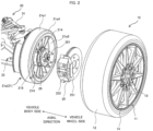
FIG. 1 is an exploded perspective view of a suspension device, an in-wheel motor, and a vehicle wheel according to an embodiment of the present invention.FIG. 2 is an exploded perspective view of the suspension device, the in-wheel motor, and the vehicle wheel in a state where the suspension device and the in-wheel motor according to the embodiment of the present invention are assembled.FIG. 3 is a perspective view in a state where the suspension device and the in-wheel motor according to the embodiment of the present invention are assembled.FIG. 4 is a perspective view in a state where the suspension device, the in-wheel motor, and the vehicle wheel according to the embodiment of the present invention are assembled. - In
FIGS. 1 to 4 , only one wheel is shown. When a vehicle has four vehicle wheels, it is possible to provide an in-wheel motor on at least one vehicle wheel. - The
vehicle wheel 10 includes awheel 11 and atire 12 mounted to the outer periphery of thewheel 11. Thewheel 11 includes a plurality ofspokes 13 radially extending radially outward from a central portion, and arim 14 joined to thespokes 13. Thetire 12 is mounted to the outer periphery of therim 14. Thespokes 13 are disposed offset so as to be located outside the vehicle with respect to the width direction of therim 14. - An in-
wheel motor 20 that rotationally drives thewheel 11 is connected to thevehicle wheel 10. At least a part of the in-wheel motor 20 is disposed inside thewheel 11. - The in-
wheel motor 20 of the present embodiment refers to a driving means of a vehicle wheel housed in thewheel 11. The in-wheel motor 20 includes an inner rotor type and an outer rotor type, and further includes one including a reduction gear and one not including a reduction gear, and can be roughly classified into four types. In the present embodiment, an inner rotor type including no reduction gear (direct drive) will be described as an example, but an outer rotor type may be used. - The in-
wheel motor 20 includes astator housing 21a that is open on one side in the axial direction, arotor 22 that is inserted into thestator housing 21a from the open side of thestator housing 21a and rotates inside thestator housing 21a, astator housing cover 21b that closes the open side of thestator 21, aninverter device 24 fixed to thestator housing cover 21b, abrake device 25 fixed to the opposite open side of thestator housing 21a, and a hub bearing 26 that is rotatably supported by thestator housing 21a and rotates together with abrake disc 251 and thevehicle wheel 10. - The hub bearing 26 is fixed to a hub bearing
mounting portion 216 formed in a central portion of thestator housing 21a. The hub bearing 26 includes a plurality of (five in the present embodiment)hub bolts 261. Thehub bolt 261 penetrates thebrake disc 251. Thevehicle wheel 10 is fixed to the hub bearing 26 by inserting thehub bolt 261 into a through hole of thewheel 11 and screwing a nut 262 (FIG. 8 ) . - In the present embodiment, the stator housing 21a and the
stator housing cover 21b constitute thestator 21. Thestator 21 supports theinverter device 24, thebrake device 25, the hub bearing 26, and the like, and is mounted to thesuspension device 30 on the vehicle body side. As a result, the in-wheel motor 20 is supported by the vehicle body via thesuspension device 30. Thesuspension device 30 of the present embodiment is an independent suspension installed in each vehicle wheel. The in-wheel motor 20 is supported by the vehicle body by the independent suspension. The independent suspension can improve followability to unevenness of a road surface, and can improve ride comfort and steering operability. - In the in-
wheel motor 20, the stator 21 (the stator housing 21a and thestator housing cover 21b) and therotor 22 disposed inside thestator 21 constitute a motor that drives the wheel 11 (vehicle wheel 10). Theinverter device 24 supplies power to the motor. - In a steering wheel that is a vehicle wheel that changes a direction of a vehicle body, it is preferable to reduce an interval (scrubbing radius) between an intersection of a tire ground contact surface and a king-pin shaft that is a rotation center of steering and a center line in a width direction of the tire when viewed from a vehicle traveling direction. When the in-wheel motor is attached to the wheel, the axial direction of the in-wheel motor protrudes toward the vehicle body, the king-pin shaft is separated from the center position of the tire, and the scrubbing radius tends to be large. When the scrubbing radius increases, a large reaction force is applied to a steering mechanism at the time of steering operation, and the steering is easily taken by undulation or a step on a rough road surface when the vehicle travels on the rough road surface. In addition, when the steering wheel also serves as the drive wheel, the driving force becomes a rotational moment around the king-pin shaft, and thus there is a concern about deterioration in controllability and ride comfort. Therefore, it is preferable to reduce the length of the in-wheel motor in the axial direction. On the other hand, in order to improve the drive torque of the motor, it is preferable to increase the outer diameter of the motor. Means for solving these problems will be described below.
-
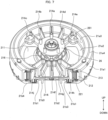
FIG. 5 is a front view of the in-wheel motor according to the embodiment of the present invention as viewed from the vehicle wheel side.FIG. 6 is a cross-sectional view taken along line VI-VI ofFIG. 5 .FIG. 7 is a cross-sectional perspective view of a part of the in-wheel motor according to the embodiment of the present invention when viewed obliquely downward on the vehicle wheel side. - One side (the vehicle body side in the present embodiment) of the
stator housing 21a in the axial direction is opened. Thestator housing 21a includes a cylindrical housing annular portion 21a1 extending in the axial direction, a housing flat plate portion 21a2 extending in the radial direction orthogonal to the axial direction, a folded portion 21a3 extending in the axial direction and having one end connected to the housing flat plate portion 21a2, and a flange portion 21a4 extending in the radial direction orthogonal to the axial direction and having one end connected to the other end of the folded portion 21a3 and having the other end connected to the housing annular portion 21a1. - The housing flat plate portion 21a2 is disposed on the open portion side (the vehicle body side in the present embodiment) from the position of the flange portion 21a4 (end portion of the housing annular portion 21a1 on the opposite open portion side) via the folded portion 21a3. In other words, the housing flat plate portion 21a2 is disposed to be recessed from the position of the flange portion 21a4 (end portion of the housing annular portion 21a1 on the opposite open portion side) toward the open portion side (the vehicle body side in the present embodiment). That is, the
stator housing 21a is formed with ahousing recess 211 that is recessed from the position of the flange portion 21a4 (end portion on the opposite open portion side) toward the open portion side. Thehousing recess 211 is formed by the housing flat plate portion 21a2 and the folded portion 21a3. - The housing flat plate portion 21a2 is located on the open portion side (the vehicle body side in the present embodiment) with respect to the center position of the housing annular portion 21a1 in the axial direction. In addition, a plurality of
stator cores 212 are disposed radially inside the housing annular . portion 21a1 of thestator housing 21a, and thestator coil 213 is attached to thestator core 212. - The hub
bearing mounting portion 216 fixed to the housing flat plate portion 21a2 is provided in a radially central portion of thehousing recess 211. Thehub bearing 26 is mounted to the inner periphery of the hubbearing mounting portion 216. Since a part of the hub bearing 26 is positioned in thehousing recess 211, when thewheel 11 is mounted to the in-wheel motor 20, the in-wheel motor 20 is accommodated in thewheel 11. - The
stator housing cover 21b is disposed so as to close the open side of thestator housing 21a. Thestator housing cover 21b includes a ring-shaped housing cover flange portion 21b4 extending in the radial direction orthogonal to the axial direction and located on the outer peripheral side, a cylindrical housing cover annular portion 21b1 extending in the axial direction and having one end connected to the housing cover flange portion 21b4, a housing cover flat plate portion 21b2 connected to the other end of the housing cover annular portion 21b1 and extending in the radial direction orthogonal to the axial direction, and a rib 21b3 as a reinforcing member provided in the housing cover flat plate portion 21b2. The housing cover flange portion 21b4 is connected to and fixed to the housing annular portion 21a1 of thestator housing 21a. - The housing cover flat plate portion 21b2 is formed to be positioned on the opposite open portion side (the vehicle wheel side in the present embodiment) from the position of the housing cover flange portion 21b4 in a state where the
stator housing cover 21b closes the open side of thestator housing 21a. In other words, the housing cover flat plate portion 21b2 is disposed to be recessed from the position of the housing cover flange portion 21b4 toward the opposite open portion side (the vehicle wheel side in the present embodiment). In thestator housing cover 21b, ahousing cover recess 215 recessed from the position of the housing cover flange portion 21b4 (end portion on the open portion side) toward the opposite open portion side is formed, and a rib 21b3 is disposed in thehousing cover recess 215. - The housing cover flange portion 21b4 is connected to and fixed to the housing annular portion 21a1 of the
stator housing 21a. A space is formed inside thestator 21. - In the space inside the
stator 21, therotor 22 for rotationally driving the vehicle wheel is disposed. Therotor 22 includes arotation shaft 223. Therotor 22 includes acylindrical rotor housing 22a extending in the axial direction and a rotorflat plate portion 22b extending in the radial direction orthogonal to the axial direction and including therotation shaft 223. The rotorflat plate portion 22b is disposed closer to the vehicle body side from the center position of therotor housing 22a in the axial direction. Therefore, therotor housing 22a is disposed at a position overlapping thehousing recess 211 in the radial direction. At least a part of the hub bearing 26 is disposed at a position overlapping therotor housing 22a in the radial direction. - On the radially outer side of the
rotor housing 22a, twosupport portions 22c protruding radially outward are formed. - In addition, a plurality of
permanent magnets 221 are provided on the radially outer side of therotor housing 22a so as to be sandwiched by thesupport portions 22c. Thepermanent magnets 221 are disposed so as to face thestator core 212 with a predetermined gap. Furthermore, on the radially outer side of therotor housing 22a, afirst bearing 222a and asecond bearing 222b asmotor bearings 222 that rotatably support therotor 22 with respect to thestator 21 are provided. Thefirst bearing 222a is disposed on the vehicle body side, and thesecond bearing 222b is disposed on the vehicle wheel side opposite to the vehicle body side. Themotor bearing 222 has rolling elements between the outer ring portion and the inner ring portion. - The
brake device 25 is mounted to thestator housing 21a. Thebrake device 25 includes abrake disc 251 that rotates together with therotor 22, the hub bearing 26, and thewheel 11, and abrake caliper 252 that applies a frictional force to thebrake disc 251 to apply a brake to the wheel. - The
brake device 25 operates in the same direction as the axial direction of therotation shaft 223 of the motor. - A brake device for a vehicle which drives vehicle wheels by a motor is mainly an electric brake such as a regenerative brake or a waste electric brake, but it is also necessary to provide a mechanical brake in preparation for an electric brake failure at the time of sudden braking or full charge. Examples of the mechanical brake include a drum brake and a disc brake. In order to improve controllability of the brake device, a disc brake is used as a mechanical brake in the present embodiment.
- As illustrated in
FIG. 6 , a part of thebrake device 25 is accommodated in thehousing recess 211 of thestator housing 21a. As a result, the overall length of the in-wheel motor 20 in the axial direction can be shortened. - The
housing recess 211 of thestator housing 21a is provided with a plurality of ribs 214 (reinforcing members) connecting the folded portion 21a3 and the hubbearing mounting portion 216. - As shown in
FIGS. 5 and7 , the plurality ofribs 214 are radially disposed vertically from the hubbearing mounting portion 216. Among the plurality ofribs 214 disposed on the upper side, arib 214a is disposed at a position in the vertical direction (90 degrees) from the horizontal position. Arib 214b is disposed in a direction opening from therib 214a by 20 degrees, that is, at a position 110 degrees from the horizontal position. Arib 214c is disposed in a direction opening from therib 214a by 40 degrees, that is, at a position 130 degrees from the horizontal position. Arib 214d is disposed in a direction closing 20 degrees from therib 214a, that is, at a position 70 degrees from the horizontal position. Arib 214e is disposed in a direction closing 40 degrees from therib 214a, that is, at a position 50 degrees from the horizontal position. - On the other hand, among the plurality of
ribs 214 disposed on the lower side, a rib 214f. is disposed at a position in the vertical direction (270 degrees). Arib 214g is disposed in a direction opening from therib 214g by 20 degrees, that is, at a position 290 degrees from the horizontal position. Arib 214h is disposed in a direction opening from therib 214f by 40 degrees, that is, at a position 310 degrees from the horizontal position. Arib 214i is disposed in a direction closing 20 degrees from therib 214f, that is, at a position 250 degrees from the horizontal position. Arib 214j is disposed in a direction closing 40 degrees from therib 214a, that is, at a position 230 degrees from the horizontal position. - In the present embodiment, a part of the
brake device 25 is disposed to be accommodated in thehousing recess 211 of thestator housing 21a. In order to avoid interference between therib 214 and thebrake device 25, no rib is formed between therib 214c and therib 214i and between therib 214e and therib 214h in the present embodiment. In the present embodiment, thebrake device 25 is disposed in thehousing recess 211 in which norib 214 is formed. - A part of the
brake caliper 252 is disposed at a position overlapping the stator 21 (stator housing 21a) in the radial direction. Thebrake caliper 252 is disposed on the inner diameter side of thestator core 212. The axial end surface (part of the axial end portion) of the brake caliper 252 (brake device 25) is in contact with the housing flat plate portion 21a2 (stator 21). In other words, the axial end surface of the brake caliper 252 (brake device 25) and the housing flat plate portion 21a2 (stator 21) are in surface contact with each other. - The
rib 214 functions as a reinforcing member of thestator 21, and the strength between therib 214c and therib 214i and between therib 214e and therib 214h decreases. The travelingvehicle wheel 10 receives a load in the up-down direction due to the unevenness of the road surface. The in-wheel motor 20 provided in thevehicle wheel 10 receives a load in the up-down direction similarly to thevehicle wheel 10. Therefore, therib 214 disposed in thestator housing 21a may be disposed so as to receive a load in the up-down direction, and even when therib 214 is not disposed between therib 214c and therib 214i and between therib 214e and therib 214h, the strength of thestator 21 can be ensured. In the present embodiment, since therib 214 is not disposed between therib 214c and therib 214i and between therib 214e and therib 214h, the in-wheel motor 20 can be reduced in weight, and the underspring mass can be reduced. In the present embodiment, the followability of thesuspension device 30 to the unevenness of the road surface is improved by reducing the underspring mass, and the ride comfort of the vehicle can be improved. - In order to ensure the strength of the
stator 21 in the vertical direction, therib 214 may be provided in a range of 45 degrees in the opening direction and the closing direction from the vertical position, that is, in a range of 45 degrees to 135 degrees from the horizontal position in the upper portion and in a range of 225 degrees to 315 degrees from the horizontal position in the lower portion. - Furthermore, in the present embodiment, the
brake caliper 252 is disposed such that the longitudinal direction thereof is the up-down direction (vertical direction). Both end portions of thebrake caliper 252 are fixed to the stator 21 (stator housing 21a) by fixingbolts 255a and 255b. That is, the upper portion of thebrake caliper 252 is fixed to thestator housing 21a by the fixingbolt 255a, and the lower portion of thebrake caliper 252 is fixed to thestator housing 21a by the fixing bolt 255b. In the present embodiment, since thebrake caliper 252 is disposed such that the longitudinal direction thereof is the up-down direction (vertical direction), a load in the up-down direction can be received by thebrake caliper 252 itself, and the strength of thestator 21 can be improved. In addition, since thebrake caliper 252 is fixed to thestator housing 21a from the vehicle wheel 10 (wheel 11) side, it is easy to approach thebrakecaliper 252, and workability such as replacement of thebrake pad 254 attached to thebrake caliper 252 can be improved. - The
brake caliper 252 includespistons brake disc 251 interposed therebetween, and abrake pad 254 that is pressed against thebrake disc 251 by thepistons brake pad 254 generates a braking force so as to sandwich thebrake disc 251. Thebrake disc 251 is installed between the hub bearing 26 and thewheel 11. Thebrake disc 251 may be a ventilated disc or a solid disc. The material of thebrake disc 251 is cast iron or the like. - Since the braking force increases and the heat generation decreases as the brake device increases in size, it is preferable that the brake device increases in size (increases in diameter). On the other hand, in order to improve the torque of the motor, it is preferable to increase the diameter of the motor. When the diameters of both the brake device and the motor are increased, the brake device and the motor overlap in the axial direction, and the axial length of the in-wheel motor (brake device + motor) increases.
- In the present embodiment, the brake device is downsized, and a part thereof is accommodated in the
housing recess 211 of thestator housing 21a. As a result, the overall length of the in-wheel motor 20 in the axial direction can be shortened. - Next, a connection relationship between the in-
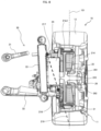
wheel motor 20 and thesuspension device 30 will be described.FIG. 8 is a cross-sectional view taken along line VIII-VIII ofFIG. 4 . - The suspension device includes an
upper arm 31 located at an upper portion, a lower arm located at a lower portion, and ashock absorber 33 that attenuates vibration. - The
stator housing cover 21b includes an upperarm mounting portion 217 to which theupper arm 31 is mounted and a lowerarm mounting portion 218 to which thelower arm 32 is mounted. - The lower
arm mounting portion 218 is disposed at a position closer to therotation shaft 223 than therotor housing 22a. The lowerarm mounting portion 218 is located closer to the vehicle wheel 10 (wheel 11) than the upperarm mounting portion 217 is. In thestator housing cover 21b of the present embodiment, thehousing cover recess 215 recessed from the position of the housing cover flange portion 21b4 (end portion on the open portion side) toward the opposite open portion side is formed, and the lowerarm mounting portion 218 is provided in thehousing cover recess 215. Therefore, the position of the lowerarm mounting portion 218 can be brought close to thewheel 11. The king-pin shaft 219 connecting the upperarm mounting portion 217 and the lowerarm mounting portion 218 is inclined so as to descend from the vehicle body side toward thevehicle wheel 10. In the present embodiment, since the position of the lowerarm mounting portion 218 is made close to thewheel 11 side, the king-pin shaft 219 and acenter line 101 of the vehicle wheel 10 (tire 12) can be made substantially coincident with each other on the ground contact surface of thetire 12. That is, in the present embodiment, the scrubbing radius can be set to zero. - The
inverter device 24 is disposed between the upperarm mounting portion 217 and the lowerarm mounting portion 218. In the present embodiment, since theinverter device 24 is disposed between the upperarm mounting portion 217 and the lowerarm mounting portion 218, theinverter device 24 can be mounted to thestator housing cover 21b without moving the king-pin shaft 219. Furthermore, since the casing of theinverter device 24 can increase the rigidity of thestator housing cover 21b, the height of the rib 21b3 in the axial direction formed in thehousing cover recess 215 of the steering 1b can be reduced, and the length of the in-wheel motor 20 in the axial direction can be reduced. - As described above, according to the present embodiment, since the
housing recess 211 is formed in thestator housing 21a and a part of the hub bearing 26 is positioned in thehousing recess 211, when thewheel 11 is mounted to the in-wheel motor 20, the in-wheel motor 20 is accommodated in thewheel 11. As a result, the length of the in-wheel motor 20 in the axial direction can be shortened, and when thesuspension device 30 is mounted to the in-wheel motor 20, the king-pin shaft 219 and the center line of thetire 12 on the ground contact surface of thetire 12 can coincide with each other. In the present embodiment, the scrubbing radius can be made zero, the reaction force at the time of the steering operation can be suppressed, and the steering can be suppressed from being taken by undulation or a step on a rough road surface when the vehicle travels on the rough road surface. - In the present embodiment, since the
housing recess 211 includes the plurality ofribs 214 as reinforcing members, the strength of thestator 21 can be ensured. - Furthermore, in the present embodiment, since the
brake device 25 is provided in thehousing recess 211, the length of the in-wheel motor 20 in the axial direction can be shortened. In addition, thebrake caliper 252 is disposed so that the longitudinal direction of thebrake caliper 252 of thebrake device 25 is the up-down direction (vertical direction) of thestator housing 21a, a load in the up-down direction can be received by thebrake caliper 252 itself, and the strength of thestator 21 can be improved. - The present invention is not limited to the embodiments described above, but includes various modifications. For example, the embodiment described above has been described in detail for easy understanding of the present invention, and is not necessarily limited to that having all the configurations described.
-
- 10
- vehicle wheel
- 11
- wheel
- 12
- tire
- 13
- spoke
- 14
- rim
- 20
- in-wheel motor
- 21
- stator
- 21a
- stator housing
- 21a1
- housing annular portion
- 21a2
- housing flat plate portion
- 21a3
- folded portion
- 21a4
- flange portion
- 21b
- stator housing cover
- 21b1
- housing cover annular portion
- 21b2
- housing cover flat plate portion
- 21b3
- rib
- 21b4
- housing cover flange portion, housing cover flange portion
- 21b422
- rotor
- 22a
- rotor housing
- 22b
- rotor flat plate portion
- 22c
- support portion
- 24
- inverter device
- 25
- brake device
- 26
- hub bearing
- 30
- suspension device
- 31
- upper arm
- 32
- lower arm
- 33
- shock absorber
- 101
- center line
- 211
- housing recess
- 212
- stator core
- 213
- stator coil
- 214, 214a to 214j
- rib
- 215
- housing cover recess
- 216
- hub bearing mounting portion
- 217
- upper arm mounting portion
- 218
- lower arm mounting portion
- 219
- king-pin shaft
- 221
- permanent magnet
- 222
- motor bearing
- 222a
- first bearing
- 222b
- second bearing
- 223
- rotation shaft
- 251
- brake disc
- 252
- brake caliper
- 253a,
- 253b piston
- 254
- brake pad
- 255a, 255b
- fixing bolt
- 261
- hub bolt
- 262
- nut
Claims (10)
- An in-wheel motor comprising a motor at least a part of which is disposed inside a wheel and which transmits power to the wheel, the in-wheel motor being supported by a vehicle by using a suspension device,.wherein the motor includes a stator and a rotor, the rotor being disposed inside the stator and including a rotation shaft,the stator includes a stator housing opened on one side and a stator housing cover closing an open portion of the stator housing,the stator housing includes a housing annular portion having a cylindrical shape and extending in an axial direction, a housing flat plate portion extending in a radial direction orthogonal to the axial direction, a folded portion extending in the axial direction and having one end connected to the housing flat plate portion, and a flange portion extending in the radial direction orthogonal to the axial direction, and having one end connected to the other end of the folded portion and an other end connected to the housing annular portion,a housing recess is formed in the stator housing by the housing flat plate portion and the folded portion,a hub bearing mounting portion which is fixed to the housing flat plate portion and to which a hub bearing is mounted is provided at a radially central portion of the housing recess,the wheel is fixed to the hub bearing via a hub bolt, andthe stator housing cover includes an upper arm mounting portion to which an upper arm of the suspension device is mounted and a lower arm mounting portion to which a lower arm is mounted.
- The in-wheel motor according to claim 1, wherein the housing recess includes a plurality of reinforcing members each connecting the housing annular portion and the hub bearing mounting portion.
- The in-wheel motor according to claim 2, wherein each of the reinforcing members is provided in a range of 45 degrees to 135 degrees from a horizontal position and in a range of 225 degrees to 315 degrees from a horizontal position.
- The in-wheel motor according to claim 1, wherein a brake device is disposed in the housing recess.
- The in-wheel motor according to any one of claims 1 to 4, whereinthe rotor includes a rotor housing having a cylindrical shape and extending in the axial direction, and a rotor flat plate portion extending in the radial direction orthogonal to the axial direction and including the rotation shaft, andthe rotor flat plate portion is disposed closer to a vehicle body side from a center position of the rotor housing in the axial direction.
- The in-wheel motor according to claim 5, wherein at least a part of the hub bearing is disposed at a position overlapping the rotor housing in the radial direction.
- The in-wheel motor according to claim 5, wherein the lower arm mounting portion is disposed at a position closer to the rotation shaft than the rotor housing.
- The in-wheel motor according to claim 7, whereinthe stator housing cover includes a housing cover recess recessed toward an opposite open portion side of the stator housing, andthe lower arm mounting portion is provided in the housing cover recess.
- The in-wheel motor according to claim 8, whereinthe stator housing cover includes an inverter device that supplies power to the motor, andthe inverter device is disposed between the upper arm mounting portion and the lower arm mounting portion.
- The in-wheel motor according to any one of claims 1 to 9, wherein the in-wheel motor is supported by a vehicle body by using an independent suspension.
Applications Claiming Priority (2)
| Application Number | Priority Date | Filing Date | Title |
|---|---|---|---|
| JP2021140876A JP7557443B2 (en) | 2021-08-31 | 2021-08-31 | In-wheel motor |
| PCT/JP2022/026017 WO2023032447A1 (en) | 2021-08-31 | 2022-06-29 | In-wheel motor |
Publications (2)
| Publication Number | Publication Date |
|---|---|
| EP4397518A1 true EP4397518A1 (en) | 2024-07-10 |
| EP4397518A4 EP4397518A4 (en) | 2025-07-16 |
Family
ID=85412073
Family Applications (1)
| Application Number | Title | Priority Date | Filing Date |
|---|---|---|---|
| EP22864035.5A Pending EP4397518A4 (en) | 2021-08-31 | 2022-06-29 | IN-WHEEL MOTOR |
Country Status (5)
| Country | Link |
|---|---|
| US (1) | US12533944B2 (en) |
| EP (1) | EP4397518A4 (en) |
| JP (1) | JP7557443B2 (en) |
| CN (1) | CN117769499A (en) |
| WO (1) | WO2023032447A1 (en) |
Families Citing this family (3)
| Publication number | Priority date | Publication date | Assignee | Title |
|---|---|---|---|---|
| JP7583691B2 (en) * | 2021-08-31 | 2024-11-14 | 株式会社日立製作所 | In-wheel motor |
| IT202200008270A1 (en) * | 2022-04-27 | 2023-10-27 | Ferrari Spa | WHEEL DEVICE WITH INTEGRATED ELECTRIC MOTOR FOR A MOTOR VEHICLE |
| JP2025054155A (en) | 2023-09-25 | 2025-04-07 | ジーケーエヌ オートモーティブ リミテッド | In-wheel motor |
Family Cites Families (12)
| Publication number | Priority date | Publication date | Assignee | Title |
|---|---|---|---|---|
| US6566779B2 (en) | 2000-06-02 | 2003-05-20 | Kabushiki Kaisha Moric | Coil winding for DC machine |
| JP4437375B2 (en) | 2000-06-02 | 2010-03-24 | ヤマハモーターエレクトロニクス株式会社 | Brushless DC motor |
| JP3638586B2 (en) | 2001-04-16 | 2005-04-13 | 株式会社ブリヂストン | In-wheel motor mounting method and in-wheel motor system |
| DE102011081120A1 (en) | 2011-07-07 | 2013-01-10 | Schaeffler Technologies AG & Co. KG | Sealed drive system |
| CN102673380B (en) | 2012-01-18 | 2014-12-31 | 华南理工大学 | A built-in suspension integrated hub motor drives electric wheels |
| JP6136903B2 (en) | 2013-12-06 | 2017-05-31 | トヨタ自動車株式会社 | Wheel drive device |
| WO2016170807A1 (en) | 2015-04-20 | 2016-10-27 | 株式会社Fomm | Vehicle suspension structure |
| CN105270161B (en) | 2015-10-28 | 2018-10-02 | 湖北航天技术研究院特种车辆技术中心 | A kind of wheel motor driving device |
| CN107487175B (en) | 2017-07-25 | 2019-12-31 | 东风汽车公司 | An integrated hub motor drive unit |
| CN107599824B (en) * | 2017-08-15 | 2019-07-26 | 湖北航天技术研究院特种车辆技术中心 | A low-speed high-torque single-stage reducer electric wheel |
| CN209505431U (en) | 2018-12-18 | 2019-10-18 | 深圳市大富科技股份有限公司 | A kind of hub motor, wheel and vehicle |
| CN111030350B (en) | 2019-12-30 | 2020-12-25 | 东风汽车集团有限公司 | Integrated central charging and discharging electric hub |
-
2021
- 2021-08-31 JP JP2021140876A patent/JP7557443B2/en active Active
-
2022
- 2022-06-29 EP EP22864035.5A patent/EP4397518A4/en active Pending
- 2022-06-29 WO PCT/JP2022/026017 patent/WO2023032447A1/en not_active Ceased
- 2022-06-29 CN CN202280052531.8A patent/CN117769499A/en active Pending
- 2022-06-29 US US18/580,134 patent/US12533944B2/en active Active
Also Published As
| Publication number | Publication date |
|---|---|
| WO2023032447A1 (en) | 2023-03-09 |
| CN117769499A (en) | 2024-03-26 |
| US20250033459A1 (en) | 2025-01-30 |
| US12533944B2 (en) | 2026-01-27 |
| JP7557443B2 (en) | 2024-09-27 |
| JP2023034574A (en) | 2023-03-13 |
| EP4397518A4 (en) | 2025-07-16 |
Similar Documents
| Publication | Publication Date | Title |
|---|---|---|
| EP4397518A1 (en) | In-wheel motor | |
| US7528518B2 (en) | In-wheel motor | |
| KR101004598B1 (en) | Wheel structure for in-wheel motor mounting | |
| KR102708798B1 (en) | In-wheel working device | |
| EP2543531B1 (en) | In-wheel motor driven device | |
| US9340103B2 (en) | In-wheel motor drive device | |
| CN104691304B (en) | Hub assembly and the vehicle for possessing above-mentioned hub assembly | |
| JP5704043B2 (en) | Wheel braking drive | |
| KR101841009B1 (en) | In-wheel working device | |
| JP5461580B2 (en) | Electric motor wheel structure | |
| WO2011058844A1 (en) | In-wheel motor driving device | |
| KR20140081351A (en) | In-wheel motor assembly | |
| US20220048317A1 (en) | Braking structure for in-wheel motor drive device | |
| JP5292626B2 (en) | In-wheel motor drive device and casing for in-wheel motor drive device | |
| JP4730078B2 (en) | In-wheel motor | |
| JP5374326B2 (en) | In-wheel motor drive device | |
| JP2013147177A (en) | Driving device, and in-wheel motor drive device | |
| JP2008273406A (en) | Wheel drive device | |
| EP4397519A1 (en) | In-wheel motor | |
| JP5736069B2 (en) | In-wheel motor drive device | |
| KR102466954B1 (en) | Wheel Assembly Mounting Inwheel Motor | |
| CN112912265A (en) | Combination structure of hub motor driving device and brake caliper | |
| JP5523860B2 (en) | In-wheel motor drive device | |
| JP2014206193A (en) | Drive unit | |
| JP2006117124A (en) | Wheel structure |
Legal Events
| Date | Code | Title | Description |
|---|---|---|---|
| STAA | Information on the status of an ep patent application or granted ep patent |
Free format text: STATUS: THE INTERNATIONAL PUBLICATION HAS BEEN MADE |
|
| PUAI | Public reference made under article 153(3) epc to a published international application that has entered the european phase |
Free format text: ORIGINAL CODE: 0009012 |
|
| STAA | Information on the status of an ep patent application or granted ep patent |
Free format text: STATUS: REQUEST FOR EXAMINATION WAS MADE |
|
| 17P | Request for examination filed |
Effective date: 20240331 |
|
| AK | Designated contracting states |
Kind code of ref document: A1 Designated state(s): AL AT BE BG CH CY CZ DE DK EE ES FI FR GB GR HR HU IE IS IT LI LT LU LV MC MK MT NL NO PL PT RO RS SE SI SK SM TR |
|
| DAV | Request for validation of the european patent (deleted) | ||
| DAX | Request for extension of the european patent (deleted) | ||
| A4 | Supplementary search report drawn up and despatched |
Effective date: 20250616 |
|
| RIC1 | Information provided on ipc code assigned before grant |
Ipc: B60K 7/00 20060101AFI20250610BHEP |
|
| STAA | Information on the status of an ep patent application or granted ep patent |
Free format text: STATUS: EXAMINATION IS IN PROGRESS |
|
| 17Q | First examination report despatched |
Effective date: 20260108 |