EP4397478A2 - Straw corrugating unit and method - Google Patents
Straw corrugating unit and method Download PDFInfo
- Publication number
- EP4397478A2 EP4397478A2 EP24174784.9A EP24174784A EP4397478A2 EP 4397478 A2 EP4397478 A2 EP 4397478A2 EP 24174784 A EP24174784 A EP 24174784A EP 4397478 A2 EP4397478 A2 EP 4397478A2
- Authority
- EP
- European Patent Office
- Prior art keywords
- straw
- processing path
- blades
- corrugating
- seat
- Prior art date
- Legal status (The legal status is an assumption and is not a legal conclusion. Google has not performed a legal analysis and makes no representation as to the accuracy of the status listed.)
- Granted
Links
Images

Classifications
-
- B—PERFORMING OPERATIONS; TRANSPORTING
- B31—MAKING ARTICLES OF PAPER, CARDBOARD OR MATERIAL WORKED IN A MANNER ANALOGOUS TO PAPER; WORKING PAPER, CARDBOARD OR MATERIAL WORKED IN A MANNER ANALOGOUS TO PAPER
- B31F—MECHANICAL WORKING OR DEFORMATION OF PAPER, CARDBOARD OR MATERIAL WORKED IN A MANNER ANALOGOUS TO PAPER
- B31F1/00—Mechanical deformation without removing material, e.g. in combination with laminating
- B31F1/20—Corrugating; Corrugating combined with laminating to other layers
- B31F1/205—Corrugating tubes
-
- B—PERFORMING OPERATIONS; TRANSPORTING
- B31—MAKING ARTICLES OF PAPER, CARDBOARD OR MATERIAL WORKED IN A MANNER ANALOGOUS TO PAPER; WORKING PAPER, CARDBOARD OR MATERIAL WORKED IN A MANNER ANALOGOUS TO PAPER
- B31D—MAKING ARTICLES OF PAPER, CARDBOARD OR MATERIAL WORKED IN A MANNER ANALOGOUS TO PAPER, NOT PROVIDED FOR IN SUBCLASSES B31B OR B31C
- B31D5/00—Multiple-step processes for making three-dimensional [3D] articles
- B31D5/0095—Making drinking straws
-
- A—HUMAN NECESSITIES
- A47—FURNITURE; DOMESTIC ARTICLES OR APPLIANCES; COFFEE MILLS; SPICE MILLS; SUCTION CLEANERS IN GENERAL
- A47G—HOUSEHOLD OR TABLE EQUIPMENT
- A47G21/00—Table-ware
- A47G21/18—Drinking straws or the like
- A47G21/186—Details of bendable straws
Definitions
- the present invention finds advantageous application to the packing of straws, to which the following disclosure will explicitly refer without thereby losing generality.
- Straws are known which provide an intermediate corrugated portion aimed to allow the bending of the straw in order to assume, in use, the most suitable shape to satisfy the user.
- a known packing machine for straws comprises a corrugating unit provided with a conveyor which moves a series of gripping heads (each suitable to engage and hold a corresponding straw) along a processing path and between an input station in which each gripping head receives a smooth straw and an output station in which each gripping head releases a corrugated straw.
- Each gripping head comprises a support needle which is axially and perpendicularly oriented relative to the processing path and is movable between an exchange position in which the support needle is arranged on the outside of a straw and a holding position in which the support needle is at least partially arranged inside the straw.
- Each support needle has an intermediate corrugated portion which reproduces the corrugated shape that must be impressed on the straws.
- each support needle in addition to being mounted axially movable, is also mounted so as to rotate on itself around a central symmetry axis.
- the corrugating unit comprises a plurality of corrugating blades which are arranged parallel to one another and spaced apart in a fixed position along the working path so that each straw moving along the working path is held by a corresponding support needle (which in the meantime is made to rotate on itself to set the straw in rotation as well) comes into contact with the corrugating blades which, by cooperating on the opposite side of the straw with the intermediate corrugated portion of the needle, permanently deform the straw thus forming in the straw the desired intermediate corrugated portion.
- the intermediate corrugated portion of each straw has an irregular (non-uniform) shape, namely, the rings of the corrugation have different depths; this defect, although not so evident to the naked eye, is particularly negative since, when the straw is bent or compressed at the intermediate corrugated portion, the straw loses its initial circular cross section to assume a cross section markedly (and completely unwanted) elliptical-shaped.
- US10524599B1 describes a corrugating machine for imparting a series of annular corrugations to a paper straw.
- the object of the present invention is to provide a corrugating unit and method for a straw which allow to obtain an intermediate corrugated portion of a perfectly regular (uniform) shape, namely, in which all the rings of the corrugation have exactly the same depth.
- the reference number 1 indicates as a whole a straw (made of paper or plastic material) which is applied to a beverage package.
- the straw 1 has a flat end 2 (which is held by the lips of the user) and a pointed end 3 (to more effectively break through the cap that seals a dispensing opening of the package).
- the corrugating station S3 extends over a relatively extended section of the processing path P (namely, for more than 90° of angular extension of the processing path P which corresponds to more than half of the entire extension of the processing path P) and comprises a plurality of blades 12 (better illustrated in Figure 5 ), each having the shape of an arc of a circle.
- the rest position of the support arm 13 is used above all when it is necessary to test the corrugating unit 6 "on empty” , that is, when it is necessary to operate the corrugating unit 6 without straws 1 (a rather frequent operating mode during assembly, maintenance and adjustment steps of the corrugating unit 6) to ensure that the blades 12 do not accidentally come into contact with the metal parts of the seats 9 without the interposition of the straws 1 (which are not present when the corrugating unit 6 works "on empty ").
- each adjustment device 14 comprises a screw 23 which can be rotated in both directions, and a mechanical transmission 24 which transforms the rotation movement of the screw 23 into a radial translation movement of the corresponding blade 12 in both directions.
- the corrugating unit 6 described above has numerous advantages.
Landscapes
- Engineering & Computer Science (AREA)
- Mechanical Engineering (AREA)
- Making Paper Articles (AREA)
- Separation, Sorting, Adjustment, Or Bending Of Sheets To Be Conveyed (AREA)
- Auxiliary Devices For And Details Of Packaging Control (AREA)
- Ceramic Capacitors (AREA)
- Sheet Holders (AREA)
- Walking Sticks, Umbrellas, And Fans (AREA)
Abstract
Description
- The present invention relates to a corrugating unit and method for a straw.
- The present invention finds advantageous application to the packing of straws, to which the following disclosure will explicitly refer without thereby losing generality.
- Straws are known which provide an intermediate corrugated portion aimed to allow the bending of the straw in order to assume, in use, the most suitable shape to satisfy the user.
- A known packing machine for straws comprises a corrugating unit provided with a conveyor which moves a series of gripping heads (each suitable to engage and hold a corresponding straw) along a processing path and between an input station in which each gripping head receives a smooth straw and an output station in which each gripping head releases a corrugated straw. Each gripping head comprises a support needle which is axially and perpendicularly oriented relative to the processing path and is movable between an exchange position in which the support needle is arranged on the outside of a straw and a holding position in which the support needle is at least partially arranged inside the straw. Each support needle has an intermediate corrugated portion which reproduces the corrugated shape that must be impressed on the straws. Furthermore, each support needle, in addition to being mounted axially movable, is also mounted so as to rotate on itself around a central symmetry axis.
- The corrugating unit comprises a plurality of corrugating blades which are arranged parallel to one another and spaced apart in a fixed position along the working path so that each straw moving along the working path is held by a corresponding support needle (which in the meantime is made to rotate on itself to set the straw in rotation as well) comes into contact with the corrugating blades which, by cooperating on the opposite side of the straw with the intermediate corrugated portion of the needle, permanently deform the straw thus forming in the straw the desired intermediate corrugated portion.
- It has been observed that by using a known corrugating unit of the type described above, the intermediate corrugated portion of each straw has an irregular (non-uniform) shape, namely, the rings of the corrugation have different depths; this defect, although not so evident to the naked eye, is particularly negative since, when the straw is bent or compressed at the intermediate corrugated portion, the straw loses its initial circular cross section to assume a cross section markedly (and completely unwanted) elliptical-shaped.
-
US10524599B1 - The object of the present invention is to provide a corrugating unit and method for a straw which allow to obtain an intermediate corrugated portion of a perfectly regular (uniform) shape, namely, in which all the rings of the corrugation have exactly the same depth.
- According to the present invention, a corrugating unit and method for a straw are provided, according to what is established in the attached claims.
- The claims describe preferred embodiments of the present invention forming an integral part of the present description.
- The present invention will now be described with reference to the attached drawings, which illustrate a non-limiting embodiment thereof, wherein:
-
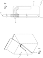
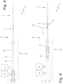
Figure 1 is a perspective view of a straw applied to a beverage package; -
Figure 2 is an enlarged scale view of the straw ofFigure 1 ; -
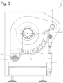
Figure 3 is a front view of a corrugating unit which forms an intermediate corrugated portion in the straw ofFigure 1 ; -
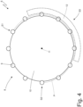
Figure 4 is a schematic view of part of the corrugating unit ofFigure 3 ; -
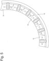
Figure 5 is an enlarged scale view of a series of blades of the corrugating unit ofFigure 3 ; -
Figures 6 and 7 are two different views of a device for adjusting the blades ofFigure 5 ; and -
Figures 8 and 9 are two views of a part of the corrugating unit ofFigure 3 in two different instants of operation. - In
Figure 1 , thereference number 1 indicates as a whole a straw (made of paper or plastic material) which is applied to a beverage package. Thestraw 1 has a flat end 2 (which is held by the lips of the user) and a pointed end 3 (to more effectively break through the cap that seals a dispensing opening of the package). - In addition, the
straw 1 has an intermediatecorrugated portion 4 in the area of which thestraw 1 can be easily bent/compressed/expanded and without breaking (namely, in an elastic manner) so as to assume, in use, the most suitable shape in order to satisfy the user. - The
straw 1 is individually packaged (namely, it has been inserted singularly in itsown wrap 5 not illustrated inFigure 1 and illustrated inFigure 2 ) after being bent in a "U" shape (i.e., by 180°) in the area of the intermediate corrugated portion 4 (the purpose of the "U" bending is to reduce the overall dimensions of thestraw 1 to remain within the dimensions of the rear or front wall of the package to which thestraw 1 is applied). - In
Figure 3 ,number 6 denotes as a whole a corrugating unit which forms the corresponding intermediatecorrugated portion 4 in eachstraw 1 and is part of a packing machine that receives thestraws 1 from a processing machine, performs the corrugation of thestraws 1, if necessary, folds thestraws 1 into a "U" shape, and inserts thestraws 1 intocorresponding wraps 5. - The
corrugating unit 6 comprises aframe 7 which rests on the ground by means of a series of feet and supports all the various components of thecorrugating unit 6. According to what is better illustrated inFigure 4 , thecorrugating unit 6 comprises aconveyor 8 which is mounted on theframe 7 and has a plurality ofseats 9, each adapted to house acorresponding straw 1; theconveyor 8 moves eachseat 9 along a processing path P which extends between an input station S1 in which theseat 9 receives asmooth straw 1 and an output station S2 in which theseat 9 releases acorrugated straw 2. Between the input station S1 and the output station S2 a corrugating station S3 is provided, along which the intermediatecorrugated portion 4 on eachstraw 1 carried by aseat 9 is formed. - In the preferred embodiment illustrated in the attached figures, the
conveyor 8 comprises adrum 10 which supports theseats 9 and is mounted on theframe 7 so as to rotate around acentral rotation axis 11; consequently, in this embodiment the processing path P is circular. According to a different and not illustrated embodiment, theconveyor 8 comprises a conveyor belt which supports theseats 9 and is wound in a ring-like manner around two end pulleys; consequently, in this embodiment the processing path P is straight. - The corrugating station S3 extends over a relatively extended section of the processing path P (namely, for more than 90° of angular extension of the processing path P which corresponds to more than half of the entire extension of the processing path P) and comprises a plurality of blades 12 (better illustrated in
Figure 5 ), each having the shape of an arc of a circle. As illustrated inFigure 5 , all theblades 12 are arranged along the processing path P, they are all oriented parallel to the processing path P (therefore they are all parallel to one another), and are mounted (indirectly) on theframe 7 so as to remain, in use, still relative to theconveyor 8 so that eachseat 9 moving along the processing path P causes thecorresponding straw 1 to come into contact with theblades 12, thus determining a deformation of thestraw 1 in the area of each blade 12 (namely, determining the formation of the intermediate corrugated portion 4). - According to a preferred embodiment, the
blades 12 are at least partially staggered along the processing path P so that not all theblades 12 can simultaneously come into contact with thestraw 1 carried by eachseat 9 moving along the processing path P. In particular, all theblades 12 are arranged staggered along the processing path P so that eachseat 9, while moving along the processing path P, causes thestraw 1 to come into contact with no more than twoblades 12 at a time and, preferably, with onesingle blade 12 at a time. In this way, the intermediatecorrugated portion 4 of eachstraw 1 is not formed all together, but a small piece (one ring) at a time. - According to what is illustrated in
Figures 3 and5 , thecorrugating unit 6 comprises asupport arm 13 which is mounted on theframe 7, is shaped like an arc of a circle in order to have the same conformation as the processing path P, and supports all theblades 12 by interposing corresponding adjustment devices 14 (better illustrated inFigures 6 and 7 ). In particular, for each blade 12 acorresponding adjustment device 14 is provided which is separate and independent of theother adjustment devices 14 and is configured to keep, in use, (namely, when thecorrugating unit 6 is in operation for normal production) itsblade 12 in a fixed work position relative to the frame 7 (therefore relative to the conveyor 8), and is configured to change, during an adjustment step with theconveyor 8 still (namely, when thecorrugating unit 6 is still for maintenance/adjustment), the work position of theblade 12 in order to move theblade 12 close to/away from the processing path P in a separate manner and independently of the work position of theother blades 12. Obviously, given the circular shape of the processing path P, eachadjustment device 14 is configured to change radially (namely, perpendicularly to therotation axis 11 of the drum 10) the work position of thecorresponding blade 12 in order to move theblade 12 close to/away from therotation axis 11 of thedrum 10. - In other words, each
adjustment device 14 is interposed between the frame 7 (namely, thearm 14 mounted on the frame 7) and acorresponding blade 12 and is configured to change the work position of thecorresponding blade 12 in order to move theblade 12 close to/away from the processing path P (namely, to theconveyor 8 which moves theseats 9 along the processing path P) in a separate manner and independently of the work position of theother blades 12. Furthermore, eachadjustment device 14 is configured to maintain, in use, thecorresponding blade 12 in a fixed work position relative to the frame 7 (namely, theconveyor 8 that moves theseats 9 along the processing path P). - Obviously, by moving the
blade 12 close to/away from the processing path P (namely, by moving theblade 12 close to/away from therotation axis 11 of the drum 10) a depth of a corrugation made by theblade 12 on thestraw 1 is increased or decreased; therefore the purpose of moving eachblade 12 close to/away from the processing path P (namely, to move ablade 12 close to/away from therotation axis 11 of the drum 10) is to change (adjust) the depth of the corrugation made byblade 12 on thestraw 1. According to what is illustrated inFigure 3 , thesupport arm 13 which supports all theadjustment devices 14 carrying theblades 12 is mounted in a movable manner on theframe 7 to move between a work position (illustrated in the attached figures) in which theblades 12 are in the area of the processing path P in order to be able to interact with thestraws 1 which move along the processing path P and therefore carry out the corrugation of thestraws 1, and a rest position, (not illustrated) in which theblades 12 are (relatively) away (actually a few centimetres) from the processing path P so as not to interact with thestraws 1 which move along or the processing path P. The rest position of thesupport arm 13 is used above all when it is necessary to test thecorrugating unit 6 "on empty", that is, when it is necessary to operate thecorrugating unit 6 without straws 1 (a rather frequent operating mode during assembly, maintenance and adjustment steps of the corrugating unit 6) to ensure that theblades 12 do not accidentally come into contact with the metal parts of theseats 9 without the interposition of the straws 1 (which are not present when thecorrugating unit 6 works "on empty"). - Preferably, the
support arm 13 is hinged so as to rotate around arotation axis 15 parallel to therotation axis 11 of thedrum 10 between the work position and the rest position. Preferably, anabutment body 16 is provided which is fixed directly on theframe 7 and forms an end stop for thesupport arm 13 to establish the work position so that, in the work position, thesupport arm 13 abuts against theabutment body 16; namely, theabutment body 16 allows to establish in a given and repeatable way the exact location of the work position of thesupport arm 13 so that the work position is certain (namely, always the same) and therefore repeatable (namely, obtainable again each time thesupport arm 13 is moved). Anactuator device 17 is preferably provided, which moves thesupport arm 13 between the work position and the rest position. In the embodiment illustrated in the attached figures, theactuator device 17 is linear (namely, it produces a linear movement) and has one end fixed (hinged) to theframe 7 and an opposite end fixed (hinged) to thesupport arm 13 at a given distance from therotation axis 15 of the support arm 13 (actually on the opposite side relative to the rotation axis 15). By way of example, theactuator device 17 has a single-acting pneumatic actuation and can assume only two positions; preferably, an elastic element of theactuator device 17 pushes thesupport arm 13 against theabutment body 16 and therefore into the work position. - As illustrated in
Figures 8 and 9 , eachseat 9 comprises asupport needle 18 which is arranged parallel to therotation axis 11 of thedrum 10 and is mounted in an axially movable manner on the conveyor 8 (namely, on the drum 10) to move perpendicular to the processing path P (i.e. parallel to the rotation axis 11) between an exchange position (illustrated inFigure 8 ) in which thesupport needle 18 is arranged outside a corresponding straw 1 (and therefore leaves thestraw 1 free) and a holding position (illustrated inFigure 9 ) in which thesupport needle 18 is at least partially arranged inside the straw 1 (and therefore engages the straw while holding the straw 1) . - The
conveyor 8 comprises anactuator device 19 which axially moves eachsupport needle 18, places thesupport needle 18 in the exchange position when theseat 9 is in the input station S1 or in the output station S2 at the two ends of the processing path P, and places thesupport needle 18 in the holding position when theseat 9 is between the input station S1 and the output station S2. In other words, when astraw 1 has to be gripped by the corresponding seat 9 (namely, in the input station S1), theactuator device 19 axially moves the support needle from the exchange position to the holding position to internally engage thestraw 1 which is arranged in the input station S1; on the other hand, when astraw 1 has to be released from the corresponding seat 9 (namely, in the output station S2), theactuator device 19 axially moves the support needle from the holding position to the exchange position to disengage thestraw 1 which is in the output station S2. Obviously, between the input station S1 and the output station S2, theactuator device 19 keeps eachsupport needle 18 in the holding position to engage thecorresponding straw 1. - It is important to note that between the input station S1 and the output station S2 (and in particular downstream of the corrugating station S3), the
actuator device 19 can modify the holding position by axially sliding thesupport needle 18 while keeping, in any case, thesupport needle 18 inside thestraw 1 to keep thestraw 1 internally engaged by thesupport needle 18; this movement of eachsupport needle 18 is meant to allow axial compression of thestraw 1 downstream of the corrugating station S3 and in the area of theintermediate portion 4. - Each
support needle 18 is mounted on theconveyor 8 in a rotary manner so as to rotate on itself around a central rotation axis 20 (parallel to therotation axis 11 of the drum 10). Theconveyor 8 comprises anactuator device 21 which rotates eachsupport needle 18 on itself and around therotation axis 20 when theseat 9 is in the corrugating station S3 (namely, when theseat 9 passes through the corrugating station S3). The rotation of eachsupport needle 18 in the area of the corrugating station S3 causes a corresponding rotation of thestraw 1 internally engaged by thesupport needle 18 and therefore allows theblades 12 to deform thestraw 1 by 360°, namely, along the entire circumferential extension of the straw 1 (hence the corrugation of thestraw 1 has a series of adjacent circular deformations). - The
actuator devices support needles 18 are preferably provided by means of cams; that is, fixed cams are provided which are arranged around therotation axis 11 of thedrum 10 and which generate the motion necessary for theactuator devices drum 10 around therotation axis 11. - Each
support needle 18 has an intermediate indented portion 22 (namely, presenting an alternation of valleys and peaks) which is arranged in the area of the intermediatecorrugated portion 4 of a straw carried by thesupport needle 18 and is configured to cooperate with theblades 12 to form the intermediatecorrugated portion 4. In other words, the intermediate indentedportion 22 of eachsupport needle 18 forms a matrix (mould) which reproduces in negative the shape of the intermediatecorrugated portion 4 of thestraw 1 whereas theblades 12 form the punches which deform thestraw 1 against the matrix (the intermediate indented portion 22). - Once the intermediate
corrugated portion 4 has been made along the corrugating station S3, eachstraw 1 could be subjected to an axial compression of the intermediatecorrugated portion 4 between the corrugating station S3 and the output station S2; for this purpose, immediately downstream of the corrugating station S3, theactuator device 19 modifies the holding position by axially sliding thesupport needle 18 so as to withdraw the intermediate indentedportion 22 of thesupport needle 18 from the intermediatecorrugated portion 4 of thestraw 1 and thus allowing the intermediatecorrugated portion 4 to be compressed without hindrance. - According to a preferred embodiment illustrated in
Figures 6 and 7 , eachadjustment device 14 comprises ascrew 23 which can be rotated in both directions, and amechanical transmission 24 which transforms the rotation movement of thescrew 23 into a radial translation movement of thecorresponding blade 12 in both directions. - According to a preferred embodiment, the
corrugating unit 6 operates on a double line, namely, treats twostraws 1 fed head on, arranged side by side (that is, axially aligned to one another) at a time. In other words, theconveyor 8 has a series of pairs of seats 9 (axially aligned to one another) to pick up twosmooth straws 1 at a time in the input station S1 and then release twocorrugated straws 1 at a time in the output station S2. According to a different embodiment, thecorrugating unit 6 operates on a single line, namely treats only onestraw 1 at a time. - Each
support needle 18 being mounted on one side only (namely, being mounted in a cantilevered manner) inevitably tends to flex when loaded and shows a bending that increases progressively while moving away from the fixing point of thesupport needle 18 to the conveyor 8 (namely, to the drum 10); consequently, as moving away from the fixing point of eachsupport needle 18 to the conveyor 8 (namely, to the drum 10), theblades 12 must be progressively closer to the processing path P (namely, to therotation axis 11 of the drum 10) to compensate for the increasingly greater bending of thesupport needle 18 and therefore create corrugations of constant depth (if instead theblades 12 were all arranged at the same distance from the processing path P then they would produce, in a completely desired way, corrugations of progressively decreasing depth due to the bending of each support needle 18). - It is important to note that the support needles 18 must have a reduced diameter in order to slip inside the corresponding
straws 1 and therefore it is impossible to make the support needles 18 rigid enough to avoid, in use, a significant bending of the same. - In other words, the
blades 12 are arranged at different distances from the processing path P (namely, from therotation axis 11 of the drum 10) and in particular theblades 12 are arranged at progressively decreasing distances from the processing path P (namely, from therotation axis 11 of the drum 10). Therefore, theblades 12 are arranged at progressively decreasing distances from the processing path P (namely, from therotation axis 11 of the drum 10) as the distance of theblades 12 increases from a cantilever mounting point of each seat 9 (namely, of the corresponding support needle 18) on theconveyor 8. The embodiments described here can be combined with one another without departing from the scope of the present invention. - The
corrugating unit 6 described above has numerous advantages. - Firstly, the
corrugating unit 6 described above allows to obtain an intermediatecorrugated portion 4 having a perfectly regular (uniform) shape, namely, in which all the rings of the corrugation have exactly the same depth. This result is essentially obtained due to the fact that the position of eachblade 12 is adjustable in a completely independent way of the position of theother blades 12 and consequently it is possible to give eachblade 12 the optimal position to obtain the optimal deformation (that is, having the desired depth) of thestraw 1 which impacts against theblade 12, compensating for all the negative effects that would determine a non-optimal deformation (that is, not having the desired depth); in particular, the adjustment of the position of eachblade 12 allows to compensate for the flexions of eachsupport needle 18 which increase as moving away from the end where thesupport needle 18 is mounted in cantilevered manner. This result is also obtained due to the fact that theblades 12 are arranged staggered along the processing path P, since only oneblade 12 at a time deforms thestraw 1 and therefore its action (not being influenced by the action of the other blades 12) is very well controllable only and solely by suitably adjusting the position of theblade 12. - Furthermore, the
corrugating unit 6 described above is simple, inexpensive and compact to manufacture.
Claims (14)
- A corrugating unit (6) for a straw (1) comprising:a frame (7);at least one seat (9) which is designed to house the straw (1); a conveyor (8), which is configured to move the seat (9) carrying the straw (1) along a processing path (P); anda corrugating station (S3), which is arranged along the processing path (P) and comprises a plurality of blades (12), which are all arranged parallel to the processing path (P) and are mounted on a frame (7) so as to remain, in use, still relative to the conveyor (8) so that the seat (9), while moving along the processing path (P), causes the straw (1) to come into contact with the blades (12), thus determining a deformation of the straw (1) in the area of each blade (12);the corrugating unit (6) is characterized in that it comprises a support arm (13), which supports all the blades (12) and is mounted in a movable manner on the frame (7), so as to move between a work position, in which the blades (12) are in the area of the processing path (P), and a rest position, in which the blades (12) are far from the processing path (P).
- The corrugating unit (6) according to claim 1, wherein the support arm (13) is hinged so as to rotate around a first rotation axis (15) between the work position and the rest position.
- The corrugating unit (6) according to claim 1 or 2 and comprising an abutment body (16) which forms an end stop for the support arm (13) in order to establish the work position so that, in the work position, the support arm (13) is in abutment against the abutment body (16).
- The corrugating unit (6) according to claim 1, 2 or 3 and comprising an actuator device (17), which moves the support arm (13) between the work position and the rest position.
- The corrugating unit (6) according to one of the claims from 1 to 4, wherein:the conveyor (8) comprises a drum (10), which supports the seat (9) and is mounted to rotate around a first central rotation axis (11);the processing path (P) is circular; andeach blade (12) has the shape of an arc of a circle.
- The corrugating unit (6) according to one of the claims from 1 to 5, wherein:the seat (9) comprises a support needle (18), which is mounted on the conveyor (8) in an axially movable manner so as to move perpendicularly to the processing path (P) between an exchange position, in which the support needle (18) is arranged on the outside of the straw (1), and a holding position, in which the support needle (18) is at least partially arranged inside the straw (1); andan actuator device (19) is provided, which axially moves the support needle (18), places the support needle (18) in the exchange position when the seat (9) is in an input station (S1) or in an output station (S2) at the two ends of the processing path (P), and places the support needle (18) in the holding position when the seat (9) is between the input station (S1) and the output station (S2).
- The corrugating unit (6) according to claim 6, wherein:the support needle (18) is mounted on the conveyor (8) in a rotary manner to rotate on itself around a second central rotation axis (20); anda third actuator device (21) is provided, which rotates the support needle (18) on itself and around the second rotation axis (20) when the seat (9) is in the corrugating station (S3).
- The corrugating unit (6) according to claim 7, wherein each adjustment device (14) is configured to radically change the work position of the corresponding blade (12) in order to move the blade (12) close to/away from the third rotation axis (11).
- The corrugating unit (6) according to one of the claims from 1 to 8, wherein the blades (12) are arranged at different distances from the processing path (P).
- The corrugating unit (6) according to claim 9, wherein the blades (12) are arranged at progressively decreasing distances from the processing path (P).
- The corrugating unit (6) according to claim 10, wherein:the seat (9) is mounted in a cantilevered manner on the conveyor (8); andthe blades (12) are arranged at progressively decreasing distances from the processing path (P) as the distance of the blades (12) increases from a cantilevered mounting point of the seat (9) on the conveyor (8).
- The corrugating unit (6) according to one of the claims from 1 to 11 and comprising a plurality of adjustment devices (14), each configured to change the work position of the blade (12) in order to move the blade (12) close to/away from the processing path (P) in a separate manner and independently of the work position of the other blades (12).
- The corrugating unit (6) according to claim 12, wherein each adjustment device (14) is configured to change the work position of the corresponding blade (12) in order to move the blade (12) close to/away from the processing path (P) in a separate manner and independently of the work position of the other blades (12) so as to increase or decrease a depth of a corrugation made by the blade (12) on the straw (1).
- A method to corrugate a straw (1) comprising the steps of: moving, by means of a conveyor (8), a seat (9) designed to house the straw (1) along a processing path (P); andcausing, by means of the seat (9) moving along the processing path (P), the straw (1) to come into contact with a plurality of blades (12), which are all arranged, in a corrugating station (S3), parallel to the processing path (P), and are mounted so as to remain, in use, still relative to the conveyor (8) in order to determine a deformation of the straw (1) in the area of each blade (12);the corrugating method is characterized in that it is provided a support arm (13), which supports all the blades (12) and is mounted in a movable manner on the frame (7), so as to move between a work position, in which the blades (12) are in the area of the processing path (P), and a rest position, in which the blades (12) are far from the processing path (P).
Applications Claiming Priority (3)
| Application Number | Priority Date | Filing Date | Title |
|---|---|---|---|
| IT102021000015836A IT202100015836A1 (en) | 2021-06-17 | 2021-06-17 | Unit and method of corrugation of a straw |
| PCT/IB2022/055583 WO2022264079A1 (en) | 2021-06-17 | 2022-06-16 | Straw corrugating unit and method |
| EP22735613.6A EP4355568A1 (en) | 2021-06-17 | 2022-06-16 | Straw corrugating unit and method |
Related Parent Applications (1)
| Application Number | Title | Priority Date | Filing Date |
|---|---|---|---|
| EP22735613.6A Division EP4355568A1 (en) | 2021-06-17 | 2022-06-16 | Straw corrugating unit and method |
Publications (3)
| Publication Number | Publication Date |
|---|---|
| EP4397478A2 true EP4397478A2 (en) | 2024-07-10 |
| EP4397478A3 EP4397478A3 (en) | 2024-10-02 |
| EP4397478B1 EP4397478B1 (en) | 2025-12-17 |
Family
ID=77801908
Family Applications (2)
| Application Number | Title | Priority Date | Filing Date |
|---|---|---|---|
| EP22735613.6A Pending EP4355568A1 (en) | 2021-06-17 | 2022-06-16 | Straw corrugating unit and method |
| EP24174784.9A Active EP4397478B1 (en) | 2021-06-17 | 2022-06-16 | Straw corrugating unit and method |
Family Applications Before (1)
| Application Number | Title | Priority Date | Filing Date |
|---|---|---|---|
| EP22735613.6A Pending EP4355568A1 (en) | 2021-06-17 | 2022-06-16 | Straw corrugating unit and method |
Country Status (3)
| Country | Link |
|---|---|
| EP (2) | EP4355568A1 (en) |
| IT (1) | IT202100015836A1 (en) |
| WO (1) | WO2022264079A1 (en) |
Families Citing this family (1)
| Publication number | Priority date | Publication date | Assignee | Title |
|---|---|---|---|---|
| EP4442448B1 (en) | 2023-04-03 | 2025-12-17 | G.D S.p.A. | Straw corrugating unit and method |
Citations (1)
| Publication number | Priority date | Publication date | Assignee | Title |
|---|---|---|---|---|
| US10524599B1 (en) | 2014-05-07 | 2020-01-07 | Hoffmaster Group, Inc. | Flexible straw and system and method of manufacturing the same |
Family Cites Families (4)
| Publication number | Priority date | Publication date | Assignee | Title |
|---|---|---|---|---|
| US3122977A (en) * | 1964-03-03 | Graham | ||
| US2985077A (en) * | 1957-12-04 | 1961-05-23 | Sidney G Graham | Machine for convoluting soda straws or the like |
| US3641884A (en) * | 1969-07-07 | 1972-02-15 | Anton Jivoin | Manufacturing flexible drinking straws |
| ES8608395A1 (en) * | 1985-08-02 | 1986-07-16 | Perfils Tecnics S A | Corrugating machine for drinking straws |
-
2021
- 2021-06-17 IT IT102021000015836A patent/IT202100015836A1/en unknown
-
2022
- 2022-06-16 EP EP22735613.6A patent/EP4355568A1/en active Pending
- 2022-06-16 WO PCT/IB2022/055583 patent/WO2022264079A1/en not_active Ceased
- 2022-06-16 EP EP24174784.9A patent/EP4397478B1/en active Active
Patent Citations (1)
| Publication number | Priority date | Publication date | Assignee | Title |
|---|---|---|---|---|
| US10524599B1 (en) | 2014-05-07 | 2020-01-07 | Hoffmaster Group, Inc. | Flexible straw and system and method of manufacturing the same |
Also Published As
| Publication number | Publication date |
|---|---|
| IT202100015836A1 (en) | 2022-12-17 |
| EP4397478A3 (en) | 2024-10-02 |
| EP4397478B1 (en) | 2025-12-17 |
| WO2022264079A1 (en) | 2022-12-22 |
| EP4355568A1 (en) | 2024-04-24 |
Similar Documents
| Publication | Publication Date | Title |
|---|---|---|
| US10299613B2 (en) | Flexible straw and system and method of manufacturing the same | |
| JP6381627B2 (en) | Actuating mechanism for vertically oriented bodymakers | |
| JP6389234B2 (en) | Tool pack for vertical body makers | |
| US20240150145A1 (en) | Surface Rewinder with Center Assist and Belt and Winding Drum Forming a Winding Nest | |
| US11643294B2 (en) | Flexible drive and core engagement members for a rewinding machine | |
| US8070472B2 (en) | Apparatus for rolling and forming food dough | |
| JP6284618B2 (en) | Can body removal mechanism for vertical body makers | |
| JP6381626B2 (en) | Cup supply mechanism for vertical body makers | |
| EP4397478B1 (en) | Straw corrugating unit and method | |
| KR101000303B1 (en) | Molding shutter device and the shutter piece | |
| RU96108263A (en) | DEVICE FOR FOLDING CARDBOARD FOR MANUFACTURE OF WRAPPING CARDBOARD BOXES | |
| EP4164875B1 (en) | Apparatus and method for shaping tubular elements | |
| US6098372A (en) | Packaging machine with movable members | |
| EP4442448B1 (en) | Straw corrugating unit and method | |
| EP4149749B1 (en) | Apparatus and method for making flexible shaped portions on tubular elements | |
| IT8247960A1 (en) | APPARATUS FOR PRODUCING A FOLDED WRAPPER IN THE SHAPE OF A PLUME, ESPECIALLY AROUND SWEETS | |
| WO2024081788A1 (en) | System for dynamically adjusting positioning of a toolpack of a can bodymaker and can bodymaker including same |
Legal Events
| Date | Code | Title | Description |
|---|---|---|---|
| PUAI | Public reference made under article 153(3) epc to a published international application that has entered the european phase |
Free format text: ORIGINAL CODE: 0009012 |
|
| STAA | Information on the status of an ep patent application or granted ep patent |
Free format text: STATUS: THE APPLICATION HAS BEEN PUBLISHED |
|
| AC | Divisional application: reference to earlier application |
Ref document number: 4355568 Country of ref document: EP Kind code of ref document: P |
|
| AK | Designated contracting states |
Kind code of ref document: A2 Designated state(s): AL AT BE BG CH CY CZ DE DK EE ES FI FR GB GR HR HU IE IS IT LI LT LU LV MC MK MT NL NO PL PT RO RS SE SI SK SM TR |
|
| PUAL | Search report despatched |
Free format text: ORIGINAL CODE: 0009013 |
|
| AK | Designated contracting states |
Kind code of ref document: A3 Designated state(s): AL AT BE BG CH CY CZ DE DK EE ES FI FR GB GR HR HU IE IS IT LI LT LU LV MC MK MT NL NO PL PT RO RS SE SI SK SM TR |
|
| RIC1 | Information provided on ipc code assigned before grant |
Ipc: A47G 21/18 20060101ALN20240829BHEP Ipc: B31D 5/00 20170101ALI20240829BHEP Ipc: B31F 1/20 20060101AFI20240829BHEP |
|
| STAA | Information on the status of an ep patent application or granted ep patent |
Free format text: STATUS: REQUEST FOR EXAMINATION WAS MADE |
|
| 17P | Request for examination filed |
Effective date: 20241003 |
|
| RBV | Designated contracting states (corrected) |
Designated state(s): AL AT BE BG CH CY CZ DE DK EE ES FI FR GB GR HR HU IE IS IT LI LT LU LV MC MK MT NL NO PL PT RO RS SE SI SK SM TR |
|
| GRAP | Despatch of communication of intention to grant a patent |
Free format text: ORIGINAL CODE: EPIDOSNIGR1 |
|
| RIC1 | Information provided on ipc code assigned before grant |
Ipc: A47G 21/18 20060101ALN20250602BHEP Ipc: B31D 5/00 20170101ALI20250602BHEP Ipc: B31F 1/20 20060101AFI20250602BHEP |
|
| STAA | Information on the status of an ep patent application or granted ep patent |
Free format text: STATUS: GRANT OF PATENT IS INTENDED |
|
| INTG | Intention to grant announced |
Effective date: 20250709 |
|
| GRAS | Grant fee paid |
Free format text: ORIGINAL CODE: EPIDOSNIGR3 |
|
| GRAA | (expected) grant |
Free format text: ORIGINAL CODE: 0009210 |
|
| STAA | Information on the status of an ep patent application or granted ep patent |
Free format text: STATUS: THE PATENT HAS BEEN GRANTED |
|
| P01 | Opt-out of the competence of the unified patent court (upc) registered |
Free format text: CASE NUMBER: UPC_APP_0011432_4397478/2025 Effective date: 20251029 |
|
| AC | Divisional application: reference to earlier application |
Ref document number: 4355568 Country of ref document: EP Kind code of ref document: P |
|
| AK | Designated contracting states |
Kind code of ref document: B1 Designated state(s): AL AT BE BG CH CY CZ DE DK EE ES FI FR GB GR HR HU IE IS IT LI LT LU LV MC MK MT NL NO PL PT RO RS SE SI SK SM TR |
|
| REG | Reference to a national code |
Ref country code: CH Ref legal event code: F10 Free format text: ST27 STATUS EVENT CODE: U-0-0-F10-F00 (AS PROVIDED BY THE NATIONAL OFFICE) Effective date: 20251217 Ref country code: GB Ref legal event code: FG4D |
|
| REG | Reference to a national code |
Ref country code: DE Ref legal event code: R096 Ref document number: 602022027245 Country of ref document: DE |
|
| REG | Reference to a national code |
Ref country code: LT Ref legal event code: MG9D |
|
| PG25 | Lapsed in a contracting state [announced via postgrant information from national office to epo] |
Ref country code: NO Free format text: LAPSE BECAUSE OF FAILURE TO SUBMIT A TRANSLATION OF THE DESCRIPTION OR TO PAY THE FEE WITHIN THE PRESCRIBED TIME-LIMIT Effective date: 20260317 |
|
| PG25 | Lapsed in a contracting state [announced via postgrant information from national office to epo] |
Ref country code: FI Free format text: LAPSE BECAUSE OF FAILURE TO SUBMIT A TRANSLATION OF THE DESCRIPTION OR TO PAY THE FEE WITHIN THE PRESCRIBED TIME-LIMIT Effective date: 20251217 Ref country code: HR Free format text: LAPSE BECAUSE OF FAILURE TO SUBMIT A TRANSLATION OF THE DESCRIPTION OR TO PAY THE FEE WITHIN THE PRESCRIBED TIME-LIMIT Effective date: 20251217 |
|
| PG25 | Lapsed in a contracting state [announced via postgrant information from national office to epo] |
Ref country code: RS Free format text: LAPSE BECAUSE OF FAILURE TO SUBMIT A TRANSLATION OF THE DESCRIPTION OR TO PAY THE FEE WITHIN THE PRESCRIBED TIME-LIMIT Effective date: 20260317 |
|
| REG | Reference to a national code |
Ref country code: NL Ref legal event code: MP Effective date: 20251217 |
|
| PG25 | Lapsed in a contracting state [announced via postgrant information from national office to epo] |
Ref country code: LV Free format text: LAPSE BECAUSE OF FAILURE TO SUBMIT A TRANSLATION OF THE DESCRIPTION OR TO PAY THE FEE WITHIN THE PRESCRIBED TIME-LIMIT Effective date: 20251217 |
|
| PG25 | Lapsed in a contracting state [announced via postgrant information from national office to epo] |
Ref country code: BG Free format text: LAPSE BECAUSE OF FAILURE TO SUBMIT A TRANSLATION OF THE DESCRIPTION OR TO PAY THE FEE WITHIN THE PRESCRIBED TIME-LIMIT Effective date: 20251217 |