EP4397462A1 - Pole chain saw - Google Patents
Pole chain saw Download PDFInfo
- Publication number
- EP4397462A1 EP4397462A1 EP23211341.5A EP23211341A EP4397462A1 EP 4397462 A1 EP4397462 A1 EP 4397462A1 EP 23211341 A EP23211341 A EP 23211341A EP 4397462 A1 EP4397462 A1 EP 4397462A1
- Authority
- EP
- European Patent Office
- Prior art keywords
- gearbox
- chain saw
- housing
- transmission gear
- pole chain
- Prior art date
- Legal status (The legal status is an assumption and is not a legal conclusion. Google has not performed a legal analysis and makes no representation as to the accuracy of the status listed.)
- Granted
Links
Images

Classifications
-
- B—PERFORMING OPERATIONS; TRANSPORTING
- B27—WORKING OR PRESERVING WOOD OR SIMILAR MATERIAL; NAILING OR STAPLING MACHINES IN GENERAL
- B27B—SAWS FOR WOOD OR SIMILAR MATERIAL; COMPONENTS OR ACCESSORIES THEREFOR
- B27B17/00—Chain saws; Equipment therefor
- B27B17/08—Drives or gearings; Devices for swivelling or tilting the chain saw
-
- B—PERFORMING OPERATIONS; TRANSPORTING
- B25—HAND TOOLS; PORTABLE POWER-DRIVEN TOOLS; MANIPULATORS
- B25F—COMBINATION OR MULTI-PURPOSE TOOLS NOT OTHERWISE PROVIDED FOR; DETAILS OR COMPONENTS OF PORTABLE POWER-DRIVEN TOOLS NOT PARTICULARLY RELATED TO THE OPERATIONS PERFORMED AND NOT OTHERWISE PROVIDED FOR
- B25F5/00—Details or components of portable power-driven tools not particularly related to the operations performed and not otherwise provided for
- B25F5/008—Cooling means
-
- B—PERFORMING OPERATIONS; TRANSPORTING
- B27—WORKING OR PRESERVING WOOD OR SIMILAR MATERIAL; NAILING OR STAPLING MACHINES IN GENERAL
- B27B—SAWS FOR WOOD OR SIMILAR MATERIAL; COMPONENTS OR ACCESSORIES THEREFOR
- B27B17/00—Chain saws; Equipment therefor
- B27B17/0008—Means for carrying the chain saw, e.g. handles
-
- B—PERFORMING OPERATIONS; TRANSPORTING
- B27—WORKING OR PRESERVING WOOD OR SIMILAR MATERIAL; NAILING OR STAPLING MACHINES IN GENERAL
- B27B—SAWS FOR WOOD OR SIMILAR MATERIAL; COMPONENTS OR ACCESSORIES THEREFOR
- B27B17/00—Chain saws; Equipment therefor
- B27B17/12—Lubricating devices specially designed for chain saws
-
- A—HUMAN NECESSITIES
- A01—AGRICULTURE; FORESTRY; ANIMAL HUSBANDRY; HUNTING; TRAPPING; FISHING
- A01G—HORTICULTURE; CULTIVATION OF VEGETABLES, FLOWERS, RICE, FRUIT, VINES, HOPS OR SEAWEED; FORESTRY; WATERING
- A01G3/00—Cutting implements specially adapted for horticultural purposes; Delimbing standing trees
- A01G3/08—Other tools for pruning, branching or delimbing standing trees
- A01G3/085—Motor-driven saws for pruning or branching
- A01G3/086—Chain saws
-
- B—PERFORMING OPERATIONS; TRANSPORTING
- B27—WORKING OR PRESERVING WOOD OR SIMILAR MATERIAL; NAILING OR STAPLING MACHINES IN GENERAL
- B27B—SAWS FOR WOOD OR SIMILAR MATERIAL; COMPONENTS OR ACCESSORIES THEREFOR
- B27B17/00—Chain saws; Equipment therefor
- B27B17/08—Drives or gearings; Devices for swivelling or tilting the chain saw
- B27B17/083—Devices for arresting movement of the saw chain
Definitions
- the present application relates to garden tools and, in particular, to a pole chain saw.
- a pole chain saw can be used for trimming branches and performing a cutting operation on an object at a high or distant position.
- the connecting rod of the chain saw is usually designed to be longer, and an electric motor, a chain, a guide plate, and the like are disposed at the front end of the connecting rod.
- most pole chain saws use plastic gearboxes and have a poor heat dissipation effect and low assembly accuracy, greatly shortening the service life of the gearbox and the transmission mechanism.
- the present application provides a pole chain saw.
- the pole chain saw includes a connecting rod and a front end assembly disposed at the front end of the connecting rod.
- the front end assembly includes an electric motor; an output device including a guide plate and a chain wound around the guide plate, where the electric motor drives the chain to rotate; a transmission assembly connecting the electric motor to the output device; and a gearbox supporting and accommodating the transmission assembly, where at least part of the gearbox is made of metal.
- the front end assembly further includes a front end housing for supporting the connecting rod, where the front end housing includes a first housing and a second housing, where a first accommodation chamber and a second accommodation chamber are formed between the first housing and the second housing.
- a transmission mechanism includes a first transmission gear, a second transmission gear, an output shaft, and a chainwheel, where a motor shaft of the electric motor drives the first transmission gear to rotate, the first transmission gear meshes with the second transmission gear to drive the second transmission gear to rotate, the second transmission gear drives the output shaft to rotate, and the output shaft drives the chainwheel to rotate to drive the chain to rotate.
- a function performed by an assembly may be performed by one assembly, multiple assemblies, one member, or multiple members.
- a function performed by a member may be performed by one member, an assembly, or a combination of members.
- the terms “computing”, “judging”, “controlling”, “determining”, “recognizing” and the like refer to the operations and processes of a computer system or similar electronic computing device (e.g., controller, processor, etc.).
- a pole chain saw 100 disclosed in the present application is a commonly used garden tool, may be a chain saw or a pole chain saw, and may be used for trimming branches and the like.
- the pole chain saw 100 may be operated and controlled by a user to trim branches.
- a front and rear direction, a left and right direction, and an up and down direction are described as directions shown in FIG. 1 .
- an oil fill hole 1453 is disposed on the front end housing. Specifically, the oil fill hole 1453 is disposed on the gearbox 145. Lubricating oil is injected through the oil fill hole 1453 into the meshing point of the first transmission gear 141 and the second transmission gear 142, so as to reduce the friction between the first transmission gear 141 and the second transmission gear 142 and improve the service life of the first transmission gear 141 and the second transmission gear 142. Specifically, the oil fill hole 1453 may be closed by a bolt.
- the pole chain saw 100 further includes a chain tensioning assembly 16.
- the chain tensioning assembly 16 can automatically adjust a gap between the chain 122 and the guide plate 121, thereby improving the adaptability of the chain 122 and the guide plate 121 and improving the cutting efficiency. It is to be understood that during daily use of the pole chain saw 100, the chain 122 is prone to loosening due to work wear. The user adjusts the distance between the guide plate 121 and the chainwheel 144 through the chain tensioning assembly 16 to tension the chain 122. Next, the structure and working principle of the chain tensioning assembly 16 are introduced in detail.
- the chain tensioning assembly 16 includes at least a transmission component and a tensioning nut 163.
- the tensioning nut 163 can drive the transmission component to rotate synchronously.
- the transmission component includes a first gear 1621, a second gear 1622, and a transmission shaft 1623.
- the first gear 1621 is formed or sleeved on the tensioning nut 163, the second gear 1622 is sleeved on an end of the transmission shaft 1623, and the other end of the transmission shaft 1623 is connected to the guide plate 121.
- the first gear 1621 meshes with the second gear 1622.
- the pole chain saw 100 further includes an oil supply assembly.
- the oil supply assembly includes an oil pot 171, an oil pump 172, and an oil pipe 173.
- the oil pot 17 is used for storing engine oil for lubricating the chain 122 or the guide plate 121.
- the front end housing 13 further includes a fixing portion 135 for fixing the oil pot 171.
- the oil pipe 173 connects the oil pot 171 to the oil pump 172. Through the oil pipe 173, the oil pump 172 pumps the engine oil in the oil pot 171 and transports the engine oil to the chain 122 or the guide plate 121, so as to lubricate the chain 122 and the guide plate 121.
Landscapes
- Life Sciences & Earth Sciences (AREA)
- Engineering & Computer Science (AREA)
- Mechanical Engineering (AREA)
- Forests & Forestry (AREA)
- Wood Science & Technology (AREA)
- Biodiversity & Conservation Biology (AREA)
- Ecology (AREA)
- Environmental Sciences (AREA)
- Sawing (AREA)
Abstract
Description
- The present application relates to garden tools and, in particular, to a pole chain saw.
- As a garden tool, a pole chain saw can be used for trimming branches and performing a cutting operation on an object at a high or distant position. The connecting rod of the chain saw is usually designed to be longer, and an electric motor, a chain, a guide plate, and the like are disposed at the front end of the connecting rod. On the market, most pole chain saws use plastic gearboxes and have a poor heat dissipation effect and low assembly accuracy, greatly shortening the service life of the gearbox and the transmission mechanism.
- An object of the present application is to solve or at least alleviate some or all of the preceding problems. For this reason, an object of the present application is to provide a pole chain saw that can enhance the heat dissipation effect of a gearbox and increase the service life of a transmission mechanism.
- To achieve the preceding object, the present application provides a pole chain saw. The pole chain saw includes a connecting rod and a front end assembly disposed at the front end of the connecting rod. The front end assembly includes an electric motor; an output device including a guide plate and a chain wound around the guide plate, where the electric motor drives the chain to rotate; a transmission assembly connecting the electric motor to the output device; and a gearbox supporting and accommodating the transmission assembly, where at least part of the gearbox is made of metal.
- In some examples, the front end assembly further includes a front end housing for supporting the connecting rod, where the front end housing includes a first housing and a second housing, where a first accommodation chamber and a second accommodation chamber are formed between the first housing and the second housing.
- In some examples, the first accommodation chamber is used for accommodating the electric motor, and the second accommodation chamber is used for accommodating the gearbox.
- In some examples, a front end housing is formed with at least one air inlet and at least one air outlet, and an airflow flowing into the front end housing from the at least one air inlet flows through the gearbox and the electric motor in sequence and then flows out from the at least one air outlet.
- In some examples, the at least one air inlet is located at the rear side of the gearbox, and the at least one air outlet is located radially outside a fan.
- In some examples, an air hole is formed on a front end housing at a position relative to the gearbox.
- In some examples, the gearbox includes a first box lid and a second box lid, where after being mounted, the first box lid and the second box lid form an accommodation space to accommodate at least part of the transmission assembly.
- In some examples, a transmission mechanism includes a first transmission gear, a second transmission gear, an output shaft, and a chainwheel, where a motor shaft of the electric motor drives the first transmission gear to rotate, the first transmission gear meshes with the second transmission gear to drive the second transmission gear to rotate, the second transmission gear drives the output shaft to rotate, and the output shaft drives the chainwheel to rotate to drive the chain to rotate.
- In some examples, the extension direction of the motor shaft is perpendicular to the extension direction of the output shaft.
- In some examples, an oil fill hole is further formed on a front end housing, where the oil fill hole extends from the front end housing to a meshing point of the first transmission gear and the second transmission gear.
- In some examples, an oil fill hole is formed on the gearbox.
- In some examples, a transmission mechanism further includes a bearing sleeved on an output shaft, and an outer race of the bearing has an interference fit with the gearbox.
- In some examples, an inner race of the bearing has a clearance fit with the output shaft.
- In some examples, at least part of the gearbox is integrally formed with a front end housing.
- To achieve the preceding object, the present application further provides a pole chain saw. The pole chain saw includes a connecting rod and a front end assembly disposed at the front end of the connecting rod. The front end assembly includes an electric motor; an output device including a guide plate and a chain wound around the guide plate, where the electric motor drives the chain to rotate; a transmission assembly connecting the electric motor to the output device; and a front end housing for supporting the electric motor and the transmission assembly, where part of the front end housing for supporting the transmission assembly is made of metal.
- In some examples, the front end housing includes a first housing and a second housing, where a first accommodation chamber and a second accommodation chamber are formed between the first housing and the second housing.
- In some examples, the first accommodation chamber is used for accommodating the electric motor, and the second accommodation chamber is used for accommodating at least part of the transmission assembly.
- To achieve the preceding object, the present application further provides a pole chain saw. The pole chain saw includes a connecting rod and a front end assembly disposed at the front end of the connecting rod. The front end assembly includes a front end housing; an electric motor disposed in the front end housing; an output device including a guide plate and a chain wound around the guide plate, where the electric motor drives the chain to rotate; a transmission assembly connecting the electric motor to the output device; and a gearbox supporting and accommodating the transmission assembly, where at least part of the gearbox is made of metal. An air hole is formed on the front end housing and is opposite to the gearbox.
- In some examples, the front end housing is formed with at least one air inlet and at least one air outlet, and an airflow flowing into the front end housing from the at least one air inlet flows through the gearbox and the electric motor in sequence and then flows out from the at least one air outlet.
- In some examples, the at least one air inlet is located at the rear side of the gearbox, and the at least one air outlet is located radially outside a fan.
-
-
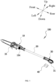
FIG. 1 is a perspective view illustrating the structure of a pole chain saw as an example of the present application; -
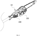
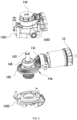
FIG. 2 is a perspective view illustrating the structure of a front end assembly of the pole chain saw inFIG. 1 ; -
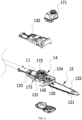
FIG. 3 is an exploded view illustrating the structure of the front end assembly inFIG. 2 ; -
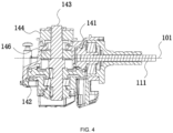
FIG. 4 is a sectional view of a transmission mechanism in the front end assembly inFIG. 2 ; -
FIG. 5 is an exploded view illustrating the structures of a transmission mechanism and an electric motor in the front end assembly inFIG. 2 ; and -
FIG. 6 is an exploded view illustrating the structure of the front end assembly inFIG. 2 from another perspective. - Before any examples of this application are explained in detail, it is to be understood that this application is not limited to its application to the structural details and the arrangement of components set forth in the following description or illustrated in the above drawings.
- In this application, the terms "comprising", "including", "having" or any other variation thereof are intended to cover an inclusive inclusion such that a process, method, article or device comprising a series of elements includes not only those series of elements, but also other elements not expressly listed, or elements inherent in the process, method, article, or device. Without further limitations, an element defined by the phrase "comprising a ..." does not preclude the presence of additional identical elements in the process, method, article, or device comprising that element.
- In this application, the term "and/or" is a kind of association relationship describing the relationship between associated objects, which means that there can be three kinds of relationships. For example, A and/or B can indicate that A exists alone, A and B exist simultaneously, and B exists alone. In addition, the character "/" in this application generally indicates that the contextual associated objects belong to an "and/or" relationship.
- In this application, the terms "connection", "combination", "coupling" and "installation" may be direct connection, combination, coupling or installation, and may also be indirect connection, combination, coupling or installation. Among them, for example, direct connection means that two members or assemblies are connected together without intermediaries, and indirect connection means that two members or assemblies are respectively connected with at least one intermediate members and the two members or assemblies are connected by the at least one intermediate members. In addition, "connection" and "coupling" are not limited to physical or mechanical connections or couplings, and may include electrical connections or couplings.
- In this application, it is to be understood by those skilled in the art that a relative term (such as "about", "approximately", and "substantially") used in conjunction with quantity or condition includes a stated value and has a meaning dictated by the context. For example, the relative term includes at least a degree of error associated with the measurement of a particular value, a tolerance caused by manufacturing, assembly, and use associated with the particular value, and the like. Such relative term should also be considered as disclosing the range defined by the absolute values of the two endpoints. The relative term may refer to plus or minus of a certain percentage (such as 1%, 5%, 10%, or more) of an indicated value. A value that did not use the relative term should also be disclosed as a particular value with a tolerance. In addition, "substantially" when expressing a relative angular position relationship (for example, substantially parallel, substantially perpendicular), may refer to adding or subtracting a certain degree (such as 1 degree, 5 degrees, 10 degrees or more) to the indicated angle.
- In this application, those skilled in the art will understand that a function performed by an assembly may be performed by one assembly, multiple assemblies, one member, or multiple members. Likewise, a function performed by a member may be performed by one member, an assembly, or a combination of members.
- In this application, the terms "up", "down", "left", "right", "front", and "rear" " and other directional words are described based on the orientation or positional relationship shown in the drawings, and should not be understood as limitations to the examples of this application. In addition, in this context, it also needs to be understood that when it is mentioned that an element is connected "above" or "under" another element, it can not only be directly connected "above" or "under" the other element, but can also be indirectly connected "above" or "under" the other element through an intermediate element. It should also be understood that orientation words such as upper side, lower side, left side, right side, front side, and rear side do not only represent perfect orientations, but can also be understood as lateral orientations. For example, lower side may include directly below, bottom left, bottom right, front bottom, and rear bottom.
- In this application, the terms "controller", "processor", "central processor", "CPU" and "MCU" are interchangeable. Where a unit "controller", "processor", "central processing", "CPU", or "MCU" is used to perform a specific function, the specific function may be implemented by a single aforementioned unit or a plurality of the aforementioned unit.
- In this application, the term "device", "module" or "unit" may be implemented in the form of hardware or software to achieve specific functions.
- In this application, the terms "computing", "judging", "controlling", "determining", "recognizing" and the like refer to the operations and processes of a computer system or similar electronic computing device (e.g., controller, processor, etc.).
- As shown in
FIG. 1 , a pole chain saw 100 disclosed in the present application is a commonly used garden tool, may be a chain saw or a pole chain saw, and may be used for trimming branches and the like. The pole chain saw 100 may be operated and controlled by a user to trim branches. In this specification, a front and rear direction, a left and right direction, and an up and down direction are described as directions shown inFIG. 1 . Specifically, when the user operates the pole chain saw 100, it is defined that a direction which the user faces is the front, a direction which the user faces away from is the rear, a direction on the left-hand side of the user is the left, a direction on the right-hand side of the user is the right, a direction facing the ground is the down, and a direction facing away from the ground is the up. - As shown in
FIGS. 1 to 6 , the pole chain saw is used as an example. The pole chain saw 100 includes afront end assembly 10 and a connectingrod 20. Thefront end assembly 10 is used for outputting and operating and is disposed at the front end of the connectingrod 20. - The
front end assembly 10 includes anelectric motor 11, anoutput device 12, and afront end housing 13. Theoutput device 12 includes aguide plate 121 and achain 122 wound around theguide plate 121. Theelectric motor 11 includes amotor shaft 111 rotatable about afirst axis 101, and the rotational output of themotor shaft 111 drives thechain 122 to rotate, thereby performing a cutting operation. Thefront end housing 13 is disposed at the front end of the connectingrod 20 and is used for supporting theelectric motor 11 and theoutput device 12. The connectingrod 20 is a long rod with a certain length so that the user can send thechain 122 to a branch or other remote positions to perform the cutting operation. - The connecting
rod 20 is fixed in thefront end housing 13 and extends into arear end housing 30. Therear end housing 30 is formed with or connected to acoupling portion 31, and apower supply device 40 is detachably connected to thecoupling portion 31 to supply electrical energy to at least theelectric motor 11. - The pole chain saw 100 further includes a
transmission mechanism 14, and thetransmission mechanism 14 connects theelectric motor 11 to theoutput device 12. Thefront end housing 13 includes afirst housing 131 and asecond housing 132. Afirst accommodation chamber 133 and asecond accommodation chamber 134 are formed between thefirst housing 131 and thesecond housing 132. Thefirst accommodation chamber 133 is used for accommodating theelectric motor 11, and thesecond accommodation chamber 134 is used for accommodating thetransmission mechanism 14. Specifically, thefirst housing 131 and thesecond housing 132 form a two-half housing structure of thefront end housing 13, and thefirst housing 131 engages with thesecond housing 132, so as to limit the positions of theelectric motor 11 and thetransmission mechanism 14. - Specifically, the
transmission mechanism 14 includes atransmission assembly 14a. Specifically, thetransmission assembly 14a includes afirst transmission gear 141, asecond transmission gear 142, anoutput shaft 143, and achainwheel 144. Thefirst transmission gear 141 and thesecond transmission gear 142 may be configured to be bevel gears. In some examples, the end of themotor shaft 111 is connected to thefirst transmission gear 141. In some examples, themotor shaft 111 and thefirst transmission gear 141 are integrally formed. Themotor shaft 111 drives thefirst transmission gear 141 to rotate, thefirst transmission gear 141 drives thesecond transmission gear 142 to rotate, thesecond transmission gear 142 drives theoutput shaft 143 to rotate synchronously, theoutput shaft 143 drives thechainwheel 144 to rotate, and thechain 122 is driven by thechainwheel 144 to move on theguide plate 121. Of course, in some examples, themotor shaft 111 and thefirst transmission gear 141 are designed as separate parts, and thefirst transmission gear 141 is sleeved on the end of themotor shaft 111. - In some examples, the
transmission mechanism 14 further includes agearbox 145. Thegearbox 145 includes afirst box lid 1451 and asecond box lid 1452. After being mounted, thefirst box lid 1451 and thesecond box lid 1452 form an accommodation space (not shown in the figure). Thefirst transmission gear 141, thesecond transmission gear 142, and theoutput shaft 143 are disposed in the preceding accommodation space. Specifically, thegearbox 145 in this example is made of metal. Thetransmission mechanism 14 further includes abearing 146 sleeved on theoutput shaft 143. Specifically, an outer race of thebearing 146 abuts against and has an interference fit with thegearbox 145. An inner ring of thebearing 146 has a clearance fit with theoutput shaft 143, thereby ensuring that theoutput shaft 143 is rotatable relative to thebearing 146. - In this manner, on the one hand, a gearbox made of metal is used so that the machining accuracy can be improved and the fit between the bearing, the front end housing, and the output shaft can be ensured. On the other hand, the preceding metal gearbox is used so that the heat dissipation effect can be enhanced and the service life of the gearbox can be increased.
- To verify the technical effect of the technical solution adopted by the chain saw in the present application, a comparison test is conducted between the chain saw in the present application and a chain saw using a traditional plastic gearbox. The test method is: to remove the chain and the guide plate, connect the machine to a 50.4V voltage regulator, and apply resistance to the output shaft of the machine through a load device to simulate the actual cutting condition of the machine. The actual test process is: to run with no load for 10s, run with a 15A load for 10s, run with a 20A load for 15s, run with a 15A load for 10s, and run with no load for 15s. The preceding process is repeated. Table 1 below is the data of the comparison test between the service life of the transmission mechanism of the chain saw in the present application and the service life of the transmission mechanism of the chain saw using the plastic gearbox.
Table 1 Test Result Table of the Service Life of the Transmission Mechanism The present application Comparison 1 Comparison 2 Comparison 3 Service life/h 340h 250h 255h 252h - The chain saw in the present application uses the metal gearbox, while Comparison 1, Comparison 2, and Comparison 3 use plastic gearboxes. As can be seen from Table 1 above, the service life of the transmission mechanism of the chain saw in the present application can be increased by at least 33% compared to the service life of the transmission mechanism of the chain saw using the plastic gearbox.
- Of course, at least part of the preceding
gearbox 145 is integrally formed with thefront end housing 13. It is to be understood that part of the front end housing for supporting thetransmission mechanism 14 is made of metal. - In some examples, the
first box lid 1451 of thegearbox 145 and thefirst housing 131 of thefront end housing 13 are integrally formed. Thesecond box lid 1452 of thegearbox 145 and thesecond housing 132 of thefront end housing 13 are integrally formed. In this manner, after thefirst housing 131 and thesecond housing 132 are assembled, the gearbox accommodating thetransmission mechanism 14 is formed. Specifically, thefirst housing 131 and thesecond housing 132 are made of metal. - In some examples, the
first box lid 1451 of thegearbox 145 and thefirst housing 131 of thefront end housing 13 are integrally formed. Thesecond box lid 1452 of thegearbox 145 and thesecond housing 132 of thefront end housing 13 are provided separately. Specifically, thefirst housing 131 and thesecond box lid 1452 are made of metal. - In some examples, the
first box lid 1451 of thegearbox 145 and thefirst housing 131 of thefront end housing 13 are provided separately. Thesecond box lid 1452 of thegearbox 145 and thesecond housing 132 of thefront end housing 13 are integrally formed. Thefirst box lid 1451 and thesecond housing 132 are made of metal. - In this manner, at least part of the
gearbox 145 is integrally formed with thefront end housing 13 so that while the service life of thetransmission mechanism 14 can be increased, the number of components can be reduced and the assembly difficulty can be reduced. - In some examples, as shown in
FIG. 5 , to lubricate thetransmission mechanism 14, anoil fill hole 1453 is disposed on the front end housing. Specifically, theoil fill hole 1453 is disposed on thegearbox 145. Lubricating oil is injected through theoil fill hole 1453 into the meshing point of thefirst transmission gear 141 and thesecond transmission gear 142, so as to reduce the friction between thefirst transmission gear 141 and thesecond transmission gear 142 and improve the service life of thefirst transmission gear 141 and thesecond transmission gear 142. Specifically, theoil fill hole 1453 may be closed by a bolt. - In this examples, the
oil fill hole 1453 is disposed on thegearbox 145. Thegearbox 145 is provided with a pillar forming theoil fill hole 1453, and the post extends to thefront end housing 13 to enable a user to input lubricating oil into theoil fill hole 1453. - In other examples, an oil fill hole may be provided on the front end housing. The front end housing is formed with a pillar, which provides the oil fill hole. The pillar extends into the meshing point of the first transmission gear and the second transmission gear so that the oil fill hole extends to the meshing point of the first transmission gear and the second transmission gear.
- Referring to
FIGS. 1 ,2 , and5 , the pole chain saw 100 further includes afan 15 disposed behind theelectric motor 11, and thefan 15 rotates about a fan axis. Thefront end housing 13 of the pole chain saw 100 is further formed with an air inlet and an air outlet. Thefan 15 is used for generating a heat dissipation airflow that enters from the air inlet and flows out from the air outlet. In this example, the air inlet includes afirst air inlet 151 disposed in front of thegearbox 145. The air outlet includes afirst air outlet 153 and asecond air outlet 154. Specifically, thefirst air outlet 153 and thesecond air outlet 154 are disposed radially outside thefan 15. In this manner, when theelectric motor 11 is started, thefan 15 is driven to rotate, and the airflow enters thefront end housing 13 from thefirst air inlet 151, flows through thegearbox 145 and theelectric motor 11, and then flows out from thefirst air outlet 153 and thesecond air outlet 154, thereby taking away the heat generated on theelectric motor 11 and thegearbox 145. - In this manner, the positions and number of the air inlets and air outlets are reasonably set, and the heat from the
gearbox 145 is effectively dissipated through the airflow, thereby improving the service life of the gearbox. - In some examples, as shown in
FIG. 6 , to further dissipate the heat from thegearbox 145, anair hole 1311 is formed on thefirst housing 131. Theair hole 1311 is opposite to thegearbox 145. In this manner, in the working process of the pole chain saw 100, the heat generated on thegearbox 145 can be dissipated from the precedingair hole 1311. - As shown in
FIGS. 1 and6 , the pole chain saw 100 further includes achain tensioning assembly 16. Thechain tensioning assembly 16 can automatically adjust a gap between thechain 122 and theguide plate 121, thereby improving the adaptability of thechain 122 and theguide plate 121 and improving the cutting efficiency. It is to be understood that during daily use of the pole chain saw 100, thechain 122 is prone to loosening due to work wear. The user adjusts the distance between theguide plate 121 and thechainwheel 144 through thechain tensioning assembly 16 to tension thechain 122. Next, the structure and working principle of thechain tensioning assembly 16 are introduced in detail. - Specifically, the
chain tensioning assembly 16 includes at least a transmission component and atensioning nut 163. Thetensioning nut 163 can drive the transmission component to rotate synchronously. The transmission component includes afirst gear 1621, asecond gear 1622, and atransmission shaft 1623. Thefirst gear 1621 is formed or sleeved on thetensioning nut 163, thesecond gear 1622 is sleeved on an end of thetransmission shaft 1623, and the other end of thetransmission shaft 1623 is connected to theguide plate 121. Thefirst gear 1621 meshes with thesecond gear 1622. When the user rotates thetensioning nut 163, thetensioning nut 163 drives thefirst gear 1621 to rotate, thefirst gear 1621 drives thesecond gear 1622 to rotate, and thesecond gear 1622 drives thetransmission shaft 1623 to move along the extension direction of theguide plate 121, thereby driving theguide plate 121 to move along the extension direction to adjust the tension of thechain 122. - As shown in
FIG. 3 , the pole chain saw 100 further includes an oil supply assembly. The oil supply assembly includes anoil pot 171, anoil pump 172, and anoil pipe 173. The oil pot 17 is used for storing engine oil for lubricating thechain 122 or theguide plate 121. Thefront end housing 13 further includes a fixingportion 135 for fixing theoil pot 171. Theoil pipe 173 connects theoil pot 171 to theoil pump 172. Through theoil pipe 173, theoil pump 172 pumps the engine oil in theoil pot 171 and transports the engine oil to thechain 122 or theguide plate 121, so as to lubricate thechain 122 and theguide plate 121. - The basic principles, main features, and advantages of this application are shown and described above. It is to be understood by those skilled in the art that the aforementioned examples do not limit the present application in any form, and all technical solutions obtained through equivalent substitutions or equivalent transformations fall within the scope of the present application.
Claims (14)
- A pole chain saw (100), comprising:a connecting rod (20); anda front end assembly (10) disposed at a front end of the connecting rod;wherein the front end assembly comprises:an electric motor (11);an output device (12) comprising a guide plate (121) and a chain (122) wound around the guide plate;a transmission assembly (14a) connecting the electric motor to the output device; anda gearbox (145) supporting and accommodating at least part of the transmission assembly, wherein at least part of the gearbox is made of metal.
- The pole chain saw of claim 1, wherein the front end assembly further comprises a front end housing (13) for supporting the connecting rod, the front end housing comprises a first housing (131) and a second housing (132), a first accommodation chamber (133) and a second accommodation chamber (134) are formed between the first housing and the second housing.
- The pole chain saw of claim 2, wherein the first accommodation chamber is used for accommodating the electric motor, and the second accommodation chamber is used for accommodating the gearbox.
- The pole chain saw of claim 2, wherein the front end housing is formed with at least one air inlet (151) and at least one air outlet (153), and an airflow flowing into the front end housing from the at least one air inlet flows through the gearbox and the electric motor in sequence and then flows out from the at least one air outlet.
- The pole chain saw of claim 4, wherein the at least one air inlet is located at a rear side of the gearbox, and the at least one air outlet is located radially outside a fan (15).
- The pole chain saw of claim 2, wherein an air hole (1311) is formed on the front end housing at a position relative to the gearbox.
- The pole chain saw of claim 1, wherein the gearbox comprises a first box lid (1451) and a second box lid (1452), wherein after being mounted, the first box lid and the second box lid form an accommodation space to accommodate at least part of the transmission assembly.
- The pole chain saw of claim 7, wherein the transmission assembly comprises a first transmission gear (141), a second transmission gear (142), an output shaft (143), and a chainwheel (144), a motor shaft (111) of the electric motor drives the first transmission gear to rotate, the first transmission gear meshes with the second transmission gear to drive the second transmission gear to rotate, the second transmission gear drives the output shaft to rotate, and the output shaft drives the chainwheel to rotate to drive the chain to rotate.
- The pole chain saw of claim 8, wherein an extension direction of the motor shaft is perpendicular to an extension direction of the output shaft.
- The pole chain saw of claim 8, wherein the front end assembly further comprises a front end housing (13) for supporting the connecting rod, an oil fill hole (1453) is further formed on the front end housing, and the oil fill hole extends from the front end housing to a meshing point of the first transmission gear and the second transmission gear.
- The pole chain saw of claim 8, wherein an oil fill hole is formed on the gearbox.
- The pole chain saw of claim 8, wherein the transmission assembly further comprises a bearing (146) sleeved on the output shaft, and an outer race of the bearing has an interference fit with the gearbox.
- The pole chain saw of claim 12, wherein an inner race of the bearing has a clearance fit with the output shaft.
- The pole chain saw of claim 1, wherein the front end assembly further comprises a front end housing (13) for supporting the connecting rod, and at least part of the gearbox is integrally formed with a front end housing.
Applications Claiming Priority (1)
| Application Number | Priority Date | Filing Date | Title |
|---|---|---|---|
| CN202320061334.4U CN219660455U (en) | 2023-01-09 | 2023-01-09 | Long rod chain saw |
Publications (2)
| Publication Number | Publication Date |
|---|---|
| EP4397462A1 true EP4397462A1 (en) | 2024-07-10 |
| EP4397462B1 EP4397462B1 (en) | 2025-04-02 |
Family
ID=87922273
Family Applications (1)
| Application Number | Title | Priority Date | Filing Date |
|---|---|---|---|
| EP23211341.5A Active EP4397462B1 (en) | 2023-01-09 | 2023-11-22 | Pole chain saw |
Country Status (3)
| Country | Link |
|---|---|
| US (1) | US20240227232A1 (en) |
| EP (1) | EP4397462B1 (en) |
| CN (1) | CN219660455U (en) |
Families Citing this family (3)
| Publication number | Priority date | Publication date | Assignee | Title |
|---|---|---|---|---|
| CN117697894A (en) * | 2024-01-12 | 2024-03-15 | 浙江马特工具有限公司 | electric chain saw |
| USD1123552S1 (en) * | 2024-04-23 | 2026-04-28 | Robert Bosch Gmbh | Chainsaw |
| EP4670491A1 (en) * | 2024-06-28 | 2025-12-31 | Zanon S.R.L. | Engine arrangement for garden equipment in general and garden equipment with such an engine arrangement |
Citations (6)
| Publication number | Priority date | Publication date | Assignee | Title |
|---|---|---|---|---|
| WO2004087385A1 (en) * | 2003-04-04 | 2004-10-14 | Aktiebolaget Electrolux | Device for a pole saw |
| US20100083513A1 (en) * | 2007-02-26 | 2010-04-08 | Roger Pellenc | Static cooling electric chain saw and method used to achieve said cooling |
| CN214430378U (en) * | 2020-08-14 | 2021-10-22 | 南京德朔实业有限公司 | Long-rod chain saw |
| CN114073201A (en) * | 2020-08-14 | 2022-02-22 | 南京德朔实业有限公司 | Long-rod chain saw |
| US20220134592A1 (en) * | 2020-10-29 | 2022-05-05 | Nanjing Chervon Industry Co., Ltd. | Chain saw |
| WO2022242525A1 (en) * | 2021-05-21 | 2022-11-24 | 格力博(江苏)股份有限公司 | Electric tool |
Family Cites Families (1)
| Publication number | Priority date | Publication date | Assignee | Title |
|---|---|---|---|---|
| CN211729513U (en) * | 2018-12-28 | 2020-10-23 | 南京德朔实业有限公司 | Chain saw |
-
2023
- 2023-01-09 CN CN202320061334.4U patent/CN219660455U/en active Active
- 2023-11-22 EP EP23211341.5A patent/EP4397462B1/en active Active
- 2023-11-27 US US18/519,466 patent/US20240227232A1/en active Pending
Patent Citations (6)
| Publication number | Priority date | Publication date | Assignee | Title |
|---|---|---|---|---|
| WO2004087385A1 (en) * | 2003-04-04 | 2004-10-14 | Aktiebolaget Electrolux | Device for a pole saw |
| US20100083513A1 (en) * | 2007-02-26 | 2010-04-08 | Roger Pellenc | Static cooling electric chain saw and method used to achieve said cooling |
| CN214430378U (en) * | 2020-08-14 | 2021-10-22 | 南京德朔实业有限公司 | Long-rod chain saw |
| CN114073201A (en) * | 2020-08-14 | 2022-02-22 | 南京德朔实业有限公司 | Long-rod chain saw |
| US20220134592A1 (en) * | 2020-10-29 | 2022-05-05 | Nanjing Chervon Industry Co., Ltd. | Chain saw |
| WO2022242525A1 (en) * | 2021-05-21 | 2022-11-24 | 格力博(江苏)股份有限公司 | Electric tool |
Also Published As
| Publication number | Publication date |
|---|---|
| US20240227232A1 (en) | 2024-07-11 |
| EP4397462B1 (en) | 2025-04-02 |
| CN219660455U (en) | 2023-09-12 |
Similar Documents
| Publication | Publication Date | Title |
|---|---|---|
| EP4397462B1 (en) | Pole chain saw | |
| DE102014109490B4 (en) | Wrist construction for an industrial robot | |
| DE112022005093T5 (en) | ROTARY IMPACT TOOL | |
| CN207827344U (en) | Automatic loading and unloading device and forging equipment with it | |
| CN203448763U (en) | Taper hole keyway broaching device and guide shaft sleeve thereof | |
| CN214430378U (en) | Long-rod chain saw | |
| EP4578271A1 (en) | Hedge trimmer | |
| CN107088664B (en) | A kind of numerical control gang drill device | |
| CN206981794U (en) | Numerical control gang drill device | |
| CN214321974U (en) | Shearing angle adjusting device of numerical control plate shearing machine | |
| CN201161346Y (en) | Cutter head power source positioning structure of drilling and tapping machine | |
| CN216478798U (en) | A gear box device for pruner | |
| CN110447408A (en) | A kind of chain saw Modularized installing structure | |
| DE102023135279A1 (en) | Fluid pump and housing with stator holder and cooling for motor and electronics | |
| CN214720871U (en) | Cutting device is used in fin processing | |
| CN219234541U (en) | AC double-shaft vertical and horizontal head | |
| CN212287973U (en) | Smart Woodworking Workbench | |
| CN210755273U (en) | Drilling equipment of machine parts processing | |
| CN214920637U (en) | Horizontal boring and milling machine tool | |
| CN223511885U (en) | Oiling machine equipment | |
| CN208163074U (en) | Numerical control cutting machine y-axis motor increases torquer | |
| FR3110939B1 (en) | TURBOMACHINE EQUIPPED WITH ELECTRIC MACHINES COUPLED TO A COUPLING SURFACE | |
| CN112548549A (en) | Intelligent screw twisting mechanism | |
| CN213827356U (en) | Multi-shaft tapping machine | |
| CN219598100U (en) | High-stability transmission structure |
Legal Events
| Date | Code | Title | Description |
|---|---|---|---|
| PUAI | Public reference made under article 153(3) epc to a published international application that has entered the european phase |
Free format text: ORIGINAL CODE: 0009012 |
|
| STAA | Information on the status of an ep patent application or granted ep patent |
Free format text: STATUS: THE APPLICATION HAS BEEN PUBLISHED |
|
| AK | Designated contracting states |
Kind code of ref document: A1 Designated state(s): AL AT BE BG CH CY CZ DE DK EE ES FI FR GB GR HR HU IE IS IT LI LT LU LV MC ME MK MT NL NO PL PT RO RS SE SI SK SM TR |
|
| STAA | Information on the status of an ep patent application or granted ep patent |
Free format text: STATUS: REQUEST FOR EXAMINATION WAS MADE |
|
| 17P | Request for examination filed |
Effective date: 20241206 |
|
| GRAP | Despatch of communication of intention to grant a patent |
Free format text: ORIGINAL CODE: EPIDOSNIGR1 |
|
| STAA | Information on the status of an ep patent application or granted ep patent |
Free format text: STATUS: GRANT OF PATENT IS INTENDED |
|
| GRAS | Grant fee paid |
Free format text: ORIGINAL CODE: EPIDOSNIGR3 |
|
| GRAA | (expected) grant |
Free format text: ORIGINAL CODE: 0009210 |
|
| STAA | Information on the status of an ep patent application or granted ep patent |
Free format text: STATUS: THE PATENT HAS BEEN GRANTED |
|
| INTG | Intention to grant announced |
Effective date: 20250211 |
|
| RIC1 | Information provided on ipc code assigned before grant |
Ipc: B27B 17/00 20060101ALN20250204BHEP Ipc: B27B 17/12 20060101ALI20250204BHEP Ipc: B25F 5/00 20060101ALI20250204BHEP Ipc: A01G 3/08 20060101ALI20250204BHEP Ipc: B27B 17/08 20060101AFI20250204BHEP |
|
| AK | Designated contracting states |
Kind code of ref document: B1 Designated state(s): AL AT BE BG CH CY CZ DE DK EE ES FI FR GB GR HR HU IE IS IT LI LT LU LV MC ME MK MT NL NO PL PT RO RS SE SI SK SM TR |
|
| REG | Reference to a national code |
Ref country code: GB Ref legal event code: FG4D |
|
| REG | Reference to a national code |
Ref country code: CH Ref legal event code: EP |
|
| REG | Reference to a national code |
Ref country code: IE Ref legal event code: FG4D |
|
| REG | Reference to a national code |
Ref country code: DE Ref legal event code: R096 Ref document number: 602023002726 Country of ref document: DE |
|
| REG | Reference to a national code |
Ref country code: NL Ref legal event code: MP Effective date: 20250402 |
|
| PG25 | Lapsed in a contracting state [announced via postgrant information from national office to epo] |
Ref country code: NL Free format text: LAPSE BECAUSE OF FAILURE TO SUBMIT A TRANSLATION OF THE DESCRIPTION OR TO PAY THE FEE WITHIN THE PRESCRIBED TIME-LIMIT Effective date: 20250402 |
|
| REG | Reference to a national code |
Ref country code: AT Ref legal event code: MK05 Ref document number: 1780871 Country of ref document: AT Kind code of ref document: T Effective date: 20250402 |
|
| PG25 | Lapsed in a contracting state [announced via postgrant information from national office to epo] |
Ref country code: FI Free format text: LAPSE BECAUSE OF FAILURE TO SUBMIT A TRANSLATION OF THE DESCRIPTION OR TO PAY THE FEE WITHIN THE PRESCRIBED TIME-LIMIT Effective date: 20250402 Ref country code: ES Free format text: LAPSE BECAUSE OF FAILURE TO SUBMIT A TRANSLATION OF THE DESCRIPTION OR TO PAY THE FEE WITHIN THE PRESCRIBED TIME-LIMIT Effective date: 20250402 Ref country code: PT Free format text: LAPSE BECAUSE OF FAILURE TO SUBMIT A TRANSLATION OF THE DESCRIPTION OR TO PAY THE FEE WITHIN THE PRESCRIBED TIME-LIMIT Effective date: 20250804 |
|
| REG | Reference to a national code |
Ref country code: LT Ref legal event code: MG9D |
|
| PG25 | Lapsed in a contracting state [announced via postgrant information from national office to epo] |
Ref country code: NO Free format text: LAPSE BECAUSE OF FAILURE TO SUBMIT A TRANSLATION OF THE DESCRIPTION OR TO PAY THE FEE WITHIN THE PRESCRIBED TIME-LIMIT Effective date: 20250702 Ref country code: GR Free format text: LAPSE BECAUSE OF FAILURE TO SUBMIT A TRANSLATION OF THE DESCRIPTION OR TO PAY THE FEE WITHIN THE PRESCRIBED TIME-LIMIT Effective date: 20250703 |
|
| PG25 | Lapsed in a contracting state [announced via postgrant information from national office to epo] |
Ref country code: PL Free format text: LAPSE BECAUSE OF FAILURE TO SUBMIT A TRANSLATION OF THE DESCRIPTION OR TO PAY THE FEE WITHIN THE PRESCRIBED TIME-LIMIT Effective date: 20250402 |
|
| PG25 | Lapsed in a contracting state [announced via postgrant information from national office to epo] |
Ref country code: BG Free format text: LAPSE BECAUSE OF FAILURE TO SUBMIT A TRANSLATION OF THE DESCRIPTION OR TO PAY THE FEE WITHIN THE PRESCRIBED TIME-LIMIT Effective date: 20250402 |
|
| PG25 | Lapsed in a contracting state [announced via postgrant information from national office to epo] |
Ref country code: HR Free format text: LAPSE BECAUSE OF FAILURE TO SUBMIT A TRANSLATION OF THE DESCRIPTION OR TO PAY THE FEE WITHIN THE PRESCRIBED TIME-LIMIT Effective date: 20250402 |
|
| PG25 | Lapsed in a contracting state [announced via postgrant information from national office to epo] |
Ref country code: AT Free format text: LAPSE BECAUSE OF FAILURE TO SUBMIT A TRANSLATION OF THE DESCRIPTION OR TO PAY THE FEE WITHIN THE PRESCRIBED TIME-LIMIT Effective date: 20250402 |
|
| PG25 | Lapsed in a contracting state [announced via postgrant information from national office to epo] |
Ref country code: RS Free format text: LAPSE BECAUSE OF FAILURE TO SUBMIT A TRANSLATION OF THE DESCRIPTION OR TO PAY THE FEE WITHIN THE PRESCRIBED TIME-LIMIT Effective date: 20250702 |
|
| PG25 | Lapsed in a contracting state [announced via postgrant information from national office to epo] |
Ref country code: IS Free format text: LAPSE BECAUSE OF FAILURE TO SUBMIT A TRANSLATION OF THE DESCRIPTION OR TO PAY THE FEE WITHIN THE PRESCRIBED TIME-LIMIT Effective date: 20250802 |
|
| PG25 | Lapsed in a contracting state [announced via postgrant information from national office to epo] |
Ref country code: LV Free format text: LAPSE BECAUSE OF FAILURE TO SUBMIT A TRANSLATION OF THE DESCRIPTION OR TO PAY THE FEE WITHIN THE PRESCRIBED TIME-LIMIT Effective date: 20250402 |
|
| REG | Reference to a national code |
Ref country code: DE Ref legal event code: R097 Ref document number: 602023002726 Country of ref document: DE |
|
| PGFP | Annual fee paid to national office [announced via postgrant information from national office to epo] |
Ref country code: DE Payment date: 20251028 Year of fee payment: 3 |
|
| PG25 | Lapsed in a contracting state [announced via postgrant information from national office to epo] |
Ref country code: DK Free format text: LAPSE BECAUSE OF FAILURE TO SUBMIT A TRANSLATION OF THE DESCRIPTION OR TO PAY THE FEE WITHIN THE PRESCRIBED TIME-LIMIT Effective date: 20250402 Ref country code: SM Free format text: LAPSE BECAUSE OF FAILURE TO SUBMIT A TRANSLATION OF THE DESCRIPTION OR TO PAY THE FEE WITHIN THE PRESCRIBED TIME-LIMIT Effective date: 20250402 |
|
| PGFP | Annual fee paid to national office [announced via postgrant information from national office to epo] |
Ref country code: FR Payment date: 20251117 Year of fee payment: 3 |
|
| PG25 | Lapsed in a contracting state [announced via postgrant information from national office to epo] |
Ref country code: CZ Free format text: LAPSE BECAUSE OF FAILURE TO SUBMIT A TRANSLATION OF THE DESCRIPTION OR TO PAY THE FEE WITHIN THE PRESCRIBED TIME-LIMIT Effective date: 20250402 |
|
| PG25 | Lapsed in a contracting state [announced via postgrant information from national office to epo] |
Ref country code: EE Free format text: LAPSE BECAUSE OF FAILURE TO SUBMIT A TRANSLATION OF THE DESCRIPTION OR TO PAY THE FEE WITHIN THE PRESCRIBED TIME-LIMIT Effective date: 20250402 |
|
| PG25 | Lapsed in a contracting state [announced via postgrant information from national office to epo] |
Ref country code: SK Free format text: LAPSE BECAUSE OF FAILURE TO SUBMIT A TRANSLATION OF THE DESCRIPTION OR TO PAY THE FEE WITHIN THE PRESCRIBED TIME-LIMIT Effective date: 20250402 |
|
| PG25 | Lapsed in a contracting state [announced via postgrant information from national office to epo] |
Ref country code: IT Free format text: LAPSE BECAUSE OF FAILURE TO SUBMIT A TRANSLATION OF THE DESCRIPTION OR TO PAY THE FEE WITHIN THE PRESCRIBED TIME-LIMIT Effective date: 20250402 |
|
| PLBE | No opposition filed within time limit |
Free format text: ORIGINAL CODE: 0009261 |
|
| STAA | Information on the status of an ep patent application or granted ep patent |
Free format text: STATUS: NO OPPOSITION FILED WITHIN TIME LIMIT |
|
| REG | Reference to a national code |
Ref country code: CH Ref legal event code: L10 Free format text: ST27 STATUS EVENT CODE: U-0-0-L10-L00 (AS PROVIDED BY THE NATIONAL OFFICE) Effective date: 20260211 |
|
| PG25 | Lapsed in a contracting state [announced via postgrant information from national office to epo] |
Ref country code: RO Free format text: LAPSE BECAUSE OF FAILURE TO SUBMIT A TRANSLATION OF THE DESCRIPTION OR TO PAY THE FEE WITHIN THE PRESCRIBED TIME-LIMIT Effective date: 20250402 |
|
| 26N | No opposition filed |
Effective date: 20260105 |