EP4397457A1 - Workpiece supply robot and workpiece supply system - Google Patents
Workpiece supply robot and workpiece supply system Download PDFInfo
- Publication number
- EP4397457A1 EP4397457A1 EP22864206.2A EP22864206A EP4397457A1 EP 4397457 A1 EP4397457 A1 EP 4397457A1 EP 22864206 A EP22864206 A EP 22864206A EP 4397457 A1 EP4397457 A1 EP 4397457A1
- Authority
- EP
- European Patent Office
- Prior art keywords
- unit
- extending
- workpiece
- robot
- hand
- Prior art date
- Legal status (The legal status is an assumption and is not a legal conclusion. Google has not performed a legal analysis and makes no representation as to the accuracy of the status listed.)
- Pending
Links
Images





Classifications
-
- B—PERFORMING OPERATIONS; TRANSPORTING
- B25—HAND TOOLS; PORTABLE POWER-DRIVEN TOOLS; MANIPULATORS
- B25J—MANIPULATORS; CHAMBERS PROVIDED WITH MANIPULATION DEVICES
- B25J15/00—Gripping heads and other end effectors
- B25J15/04—Gripping heads and other end effectors with provision for the remote detachment or exchange of the head or parts thereof
- B25J15/0491—Gripping heads and other end effectors with provision for the remote detachment or exchange of the head or parts thereof comprising end-effector racks
-
- B—PERFORMING OPERATIONS; TRANSPORTING
- B25—HAND TOOLS; PORTABLE POWER-DRIVEN TOOLS; MANIPULATORS
- B25J—MANIPULATORS; CHAMBERS PROVIDED WITH MANIPULATION DEVICES
- B25J13/00—Controls for manipulators
- B25J13/08—Controls for manipulators by means of sensing devices, e.g. viewing or touching devices
- B25J13/081—Touching devices, e.g. pressure-sensitive
- B25J13/084—Tactile sensors
-
- B—PERFORMING OPERATIONS; TRANSPORTING
- B25—HAND TOOLS; PORTABLE POWER-DRIVEN TOOLS; MANIPULATORS
- B25J—MANIPULATORS; CHAMBERS PROVIDED WITH MANIPULATION DEVICES
- B25J15/00—Gripping heads and other end effectors
- B25J15/0052—Gripping heads and other end effectors multiple gripper units or multiple end effectors
- B25J15/0061—Gripping heads and other end effectors multiple gripper units or multiple end effectors mounted on a modular gripping structure
-
- B—PERFORMING OPERATIONS; TRANSPORTING
- B25—HAND TOOLS; PORTABLE POWER-DRIVEN TOOLS; MANIPULATORS
- B25J—MANIPULATORS; CHAMBERS PROVIDED WITH MANIPULATION DEVICES
- B25J15/00—Gripping heads and other end effectors
- B25J15/04—Gripping heads and other end effectors with provision for the remote detachment or exchange of the head or parts thereof
Definitions
- the present invention relates to a workpiece supply robot and a workpiece supply system.
- the robot hand by including the extending robot hand configured to be removable, the robot hand can be partially extended without being subject to a restriction due to a common configuration of the robot hands.
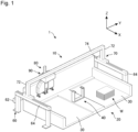
- Figure 1 is a schematic diagram showing a workpiece supply system according to an embodiment of the present invention.
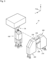
- FIGS 2 and 3 are schematic diagrams showing the workpiece supply robot of the present embodiment.
- Figure 4 is a bottom view showing the workpiece supply robot of the present embodiment.
- the workpiece supply robot 10 includes a support arm 50, a permanent robot hand 100 fixedly provided to the support arm 50 and configured to hold the workpiece W, and an extending robot hand 200 configured to hold the workpiece W together with the permanent robot hand 100.
- the extending robot hand 200 is configured to be removable.
- the workpiece supply robot 10 is configured such that the permanent robot hand 100 and the extending robot hand 200 are aligned in a straight line in a state in which the extending robot hand 200 is installed.
- the workpiece placement platform 20 includes a storage unit 40 for storing the extending robot hand 200.
- the workpiece supply system 1 is a workpiece supply system provided with an AGC (Auto Gripper Changer).
- the workpiece supply robot 10 further includes a base frame 60, a gate-shaped movable frame 70, a carriage 80, and a core unit 90.
- the base frame 60 includes a first frame unit 62 extending in a longitudinal direction of the workpiece placement platform 20 at a back of the workpiece placement platform 20, and a pair of gate-shaped second frame units 64 respectively attached to both ends of the first frame unit 62.
- the base frame 60 having such a configuration is provided so as to surround the workpiece placement platform 20 in a U-shape.
- the core unit 90 is configured such that the support arm 50 can be attached to a bottom part thereof. Further, the core unit 90 includes a rotation motor (not shown) for rotating the support arm 50 around the Z-axis. Further, the core unit 90 is configured to be able to control the X-axis motor, the Y-axis motor, the Z-axis motor, and the rotation motor. In other words, the core unit 90 is configured to be able to control movements of the movable frame 70 and the carriage 80. With such a configuration, the core unit 90 can cause the support arm 50 and the permanent robot hand 100 fixed to the support arm 50 to move in the X-, Y-, and Z-axis directions and rotate around the Z axis.
- the core unit 90 having the above configuration is configured to control the permanent robot hand 100 and the extending robot hand 200 such that the permanent robot hand 100 and the extending robot hand 200 hold the workpiece W when the permanent robot hand 100 of the workpiece supply robot 10 reaches the workpiece W placed on a workpiece placement unit 30, which will be described later, of the workpiece placement platform 20 and a surface detection unit 170, which will be described later, of the permanent robot hand 100 detects contact between the permanent robot hand 100 and the workpiece W. Further, the core unit 90 is configured to control the movable frame 70 and the carriage 80 so as to transport the held workpiece W toward a transport destination such as a working machine.
- the support arm 50 is provided in a hanging condition to the bottom part of the core unit 90 so as to be rotatable around the Z-axis.
- the permanent robot hand 100 is attached to a lower end of the support arm 50.
- the support arm 50 includes a permanent side removable unit 110 from which the extending robot hand 200 is removable.
- the support arm 50 is formed in a rectangular shape. Inside the support arm 50, there is provided a space into which wiring for supplying electric power to the permanent robot hand 100 and the permanent side removable unit 110 and piping connected to an air suctioning source, which will be described later, can be inserted.
- the permanent side removable unit 110 is configured to be able to be connected to the extending side removable unit 240, and to be able to supply the electric power to the extending robot hand 200 and supply air to the extending robot hand 200.
- Figure 6 is a schematic diagram showing the permanent robot hand of the present embodiment.
- the permanent robot hand 100 includes a permanent hand unit 120 capable of holding the workpiece W, the surface detection unit 170, a material detection unit 180, a stroke control mechanism 190, and a permanent cover 102 that covers the surface detection unit 170, the material detection unit 180, and the stroke control mechanism 190.
- the permanent hand unit 120 includes a plurality of (three in the present embodiment) air cylinders 130 and suction units 140 respectively attached to the air cylinders 130 and configured to be able to hold the workpiece W. Further, the permanent hand unit 120 includes an air cylinder for lifting-up 150 and a suction unit for lifting-up 160 attached to the air cylinder for lifting-up 150 and configured to be able to hold the workpiece W.
- the air cylinder 130 is a single-acting air cylinder that includes a piston (not shown), a piston rod 132, a cylinder tube 134, a head cover 136 attached to one end of the cylinder tube 134, a surface detection rod (not shown), and an air pressure supply port (not shown).
- the piston rod 132 is attached to one surface of the piston, and the surface detection rod is attached to a surface on an opposite side thereof.
- the piston is housed in the cylinder tube 134.
- the surface of the piston to which the surface detection rod is attached faces a side of the head cover 136 of the cylinder tube 134.
- the air pressure supply port is connected via a pipe to an air supplying source (not shown) that supplies the air.
- the suction unit 140 is attached to a distal end of the piston rod 132 of the air cylinder 130.
- the suction unit 140 is connected via a pipe to the air suctioning source (not shown) that suctions the air.
- the suction unit 140 includes a flat suction pad 142 that can suction (that can come into contact with) the surface of the workpiece W.
- the suction unit 140 is configured to suction the surface of the workpiece W placed on the workpiece placement platform 20 by a suction force of the air by the air suctioning source.
- the surface of the piston for lifting-up to which the stroke control rod is attached faces a side of the head cover for lifting-up 156 of the cylinder tube for lifting-up 154.
- the air pressure supply port for lifting-up is connected to the air supplying source via a pipe.
- the head cover for lifting-up 156 includes a rectangular portion 156a and a cylindrical portion 156b that passes through a center of the rectangular portion 156a, and configured such that a distal end of the stroke control rod is exposed from the cylindrical portion 156b when the air cylinder for lifting-up 150 contracts.
- the workpiece supply robot 10 is configured such that the respective air cylinders of the permanent robot hand 100 and the respective spring-loaded shafts of the extending robot hand 200 independently expand and contract. With such a configuration, even when the workpiece W is stacked with an inclination, the workpiece W can be held as the respective air cylinders and the respective spring-loaded shafts expand and contract in accordance with the inclination.
- the permanent robot hand 100 is configured to lift up the one end of the uppermost workpiece W from among the plurality of the workpieces W stacked on the workpiece placement platform 20.
- the workpiece supply robot 10 has an advantage that the one end of the uppermost workpiece W can be lifted up regardless of whether or not the extending robot hand 200 is installed.
- the workpiece supply system 1 includes the workpiece supply robot 10 described above and the workpiece placement platform 20, and the workpiece placement platform 20 includes the storage unit 40 for storing the extending robot hand 200.
- the workpiece supply robot 10 has an advantage that there is no need to make a movable range of the workpiece supply robot 10 larger than that of a conventional one because it is possible to install and remove the extending robot hand 200 on the workpiece placement platform 20.
- the workpiece supply robot 10 has an advantage that the extending robot hand 200 can be installed and removed in a working space that is not different from the conventional one.
- the workpiece placement platform 20 includes the plurality of the workpiece placement units 30, and the storage unit 40 is arranged in the gap between the plurality of the workpiece placement units 30.
- the workpiece supply robot 10 has an advantage that the workpiece placement platform 20 can be prevented from becoming large.
- the storage unit 40 includes the support column 42 that extends in the direction intersecting with the workpiece placement platform 20 and the hanging unit 44 that extends in the direction intersecting with the extending direction of the support column 42.
- the workpiece supply robot 10 has an advantage that the storage unit 40 can be made smaller as it is possible to hang the extending robot hand 200 for storage.
- the support arm 50 includes the permanent side removable unit 110 from which the extending robot hand 200 is removable
- the extending robot hand 200 includes the extending side removable unit 240 capable of being connected to the permanent side removable unit 110, and the electric power is supplied from the permanent robot hand 100 via the extending side removable unit 240.
- the present invention is not limited to this.
- Various arbitrary configurations can be adopted as long as the extending robot hand 200 is configured to be removable.
- the extending robot hand 200 may be configured to be removable between the support arm 50 and the permanent robot hand 100.
- the extending robot hand 200 may be configured to be removable from the permanent robot hand 100.
- the extending robot hand 200 may be configured to be removable from the core unit 90.
- the extending robot hand 200 has been described as the one being arranged substantially in a bilaterally symmetrical manner with the extending side removable unit 240 as the center.
- the present invention is not limited to this.
- the extending robot hand 200 may be arranged in a bilaterally asymmetrical manner with respect to the extending side removable unit 240.
- the permanent robot hand 100 includes the surface detection unit 170 and the surface detection unit 170 is configured to be able to detect the surface of the workpiece W.
- the present invention is not limited to this.
- the permanent robot hand 100 may not include the surface detection unit 170.
- the permanent robot hand 100 includes the material detection unit 180 and the material detection unit 180 is configured to be able to detect whether or not the workpiece W is placed on the workpiece placement platform 20.
- the present invention is not limited to this.
- the permanent robot hand 100 may not include the material detection unit 180.
- the permanent robot hand 100 is configured to lift up the one end of the uppermost workpiece W from among the plurality of the workpieces W stacked on the workpiece placement platform 20.
- the present invention is not limited to this.
- the permanent robot hand 100 may not be configured to lift up the one end of the uppermost workpiece W from among the plurality of the workpieces W stacked on the workpiece placement platform 20.
- the workpiece placement platform 20 includes the plurality of the workpiece placement units 30 and the storage unit 40 is arranged in the gap between the plurality of the workpiece placement units 30.
- the present invention is not limited to this.
- Various arbitrary configurations can be adopted such as the one in which the storage unit 40 is provided adjacent to an outside of the workpiece placement unit 30.
- the storage unit 40 has been described as the one including the support column 42 that extends in the direction intersecting with the workpiece placement platform 20 and the hanging unit 44 that extends in the direction intersecting with the extending direction of the support column 42.
- the present invention is not limited to this.
- Various arbitrary configurations can be adopted as long as the storage unit 40 is configured to be able to store the extending robot hand 200.
- the storage unit 40 may be a wall surface or a floor board.
- the hanging unit 44 has been described as the one configured to be able to hang the connection unit 230 of the extending robot hand 200.
- the present invention is not limited to this.
- the hanging unit 44 may be configured to be able to hang the first extending hand unit 210 or the second extending hand unit 220 of the extending robot hand 200.
- the workpiece supply robot 10 has been described on the assumption that it is a gantry type robot.
- the workpiece supply robot 10 may be, for example, a six-axis articulated robot or the like. If the workpiece supply robot 10 is the six-axis articulated robot, the support arm 50 corresponds to an arm unit that constitutes a robot arm of the six-axis articulated robot.
- the suction pad 142 of the suction unit 140 and the suction pad for lifting-up 162 of the suction unit for lifting-up 160 of the permanent robot hand 100 have been described as different suction pads.
- the suction pad 142 and the suction pad for lifting-up 162 may be the same suction pad.
- the suction pad 252 of the suction unit 250 and the suction pad for lifting-up 262 of the suction unit for lifting-up 260 of the extending robot hand 200 may be the same suction pad.
- the second extending hand unit 220 of the extending robot hand 200 has been described as having a different configuration from the first extending hand unit 210 thereof.
- the present invention is not limited to this.
- the second extending hand unit 220 may have the same configuration as the first extending hand unit 210.
- the air cylinder 130 and the air cylinder for lifting-up 150 of the permanent robot hand 100 and the buffer air cylinder 272 of the extending robot hand 200 have been described as the single-acting air cylinders. However, the present invention is not limited to this. These air cylinders may be, for example, double-acting air cylinders.
Landscapes
- Engineering & Computer Science (AREA)
- Robotics (AREA)
- Mechanical Engineering (AREA)
- Human Computer Interaction (AREA)
- Manipulator (AREA)
Abstract
Description
- The present invention relates to a workpiece supply robot and a workpiece supply system.
- Conventionally, a bending robot has been used in a sheet metal bending machine to automatically handle a workpiece (Patent Literature 1 and the like). The bending robot includes a robot arm, and a gripper for gripping the workpiece in a robot head unit at a tip of the robot arm. When a product to be bent is subject to a plurality of bending steps, a size, a shape, and the like of the workpiece to be clamped by the gripper are different for each of the steps. Thus, it may not be possible to clamp the workpiece with a single type of gripper. Therefore, an auto gripper changer provided with a table that includes a plurality of grippers for change has been conventionally used. The auto gripper changer is arranged in proximity to a press brake. In the auto gripper changer, the robot is configured to change a gripper to a required gripper.
- Patent Literature 1:
Japanese Patent Application Laid-Open Publication No. 8-112620 - However, in the bending robot of Patent Literature 1, it is necessary to change the gripper as a whole. Therefore, there is a problem in that a sensor necessary to detect the workpiece, a mechanism necessary to hold the workpiece, and the like need to be mounted on all the grippers for change. Further, in the bending robot of Patent Literature 1, since it is necessary to mount the sensors and the necessary mechanism, a configuration of the gripper for change is restricted. As a result, there is a problem in that expendability is limited.
- One aspect of the present invention is a workpiece supply robot and a workpiece supply system in which a robot hand can be partially extended.
- A workpiece supply robot according to one aspect of the present invention includes a support arm, a permanent robot hand fixedly provided to the support arm and configured to hold a workpiece placed on a workpiece placement platform, and an extending robot hand configured to hold the workpiece together with the permanent robot hand, in which the workpiece supply robot is configured to be able to transport the workpiece from the workpiece placement platform, and the extending robot hand is configured to be removable.
- A workpiece supply system according to one aspect of the present invention includes the workpiece supply robot and the workpiece placement platform described above, in which the workpiece placement platform includes a storage unit for storing the extending robot hand.
- According to the workpiece supply robot and the workpiece supply system according to one aspect of the present invention, by including the extending robot hand configured to be removable, the robot hand can be partially extended without being subject to a restriction due to a common configuration of the robot hands.
- According to a workpiece supply robot and a workpiece supply system according to one aspect of the present invention, a robot hand can be partially extended.
-
- [
Figure 1] Figure 1 is a schematic diagram showing a workpiece supply system according to an embodiment of the present invention. - [
Figure 2] Figure 2 is a schematic diagram showing a workpiece supply robot of the present embodiment. - [
Figure 3] Figure 3 is a schematic diagram showing the workpiece supply robot of the present embodiment. - [
Figure 4] Figure 4 is a bottom view showing the workpiece supply robot of the present embodiment. - [
Figure 5] Figure 5 is a schematic diagram showing a permanent robot hand of the present embodiment. - [
Figure 6] Figure 6 is a schematic diagram showing the permanent robot hand of the present embodiment. - [
Figure 7] Figure 7 is a side view showing the permanent robot hand of the present embodiment. - [
Figure 8] Figure 8 is a schematic diagram showing an extending robot hand of the present embodiment. - [
Figure 9] Figure 9 is a cross-sectional view showing the extending robot hand of the present embodiment. - [
Figure 10] Figure 10 is a schematic diagram showing a storage unit of the present embodiment. - [
Figure 11] Figure 11 is a side view showing the storage unit of the present embodiment. - [
Figure 12] Figure 12 is a schematic diagram showing the workpiece supply system of the present embodiment. - The best mode for carrying out the present invention will be described below by using the drawings. It should be noted that the following embodiment does not limit the invention according to each claim, and not all combinations of features described in the embodiment are essential for the solution of the invention.
-
Figure 1 is a schematic diagram showing a workpiece supply system according to an embodiment of the present invention. - First, referring to
Figure 1 , a workpiece supply system 1 according to the embodiment of the present invention will be outlined. As shown inFigure 1 , the workpiece supply system 1 according to the present embodiment roughly includes aworkpiece placement platform 20, and aworkpiece supply robot 10 configured to be able to transport, from theworkpiece placement platform 20, a workpiece W placed on theworkpiece placement platform 20. -
Figures 2 and3 are schematic diagrams showing the workpiece supply robot of the present embodiment. -
Figure 4 is a bottom view showing the workpiece supply robot of the present embodiment. - As shown in
Figure 2 , theworkpiece supply robot 10 includes asupport arm 50, apermanent robot hand 100 fixedly provided to thesupport arm 50 and configured to hold the workpiece W, and an extendingrobot hand 200 configured to hold the workpiece W together with thepermanent robot hand 100. As shown inFigure 3 , the extendingrobot hand 200 is configured to be removable. As shown inFigure 4 , theworkpiece supply robot 10 is configured such that thepermanent robot hand 100 and the extendingrobot hand 200 are aligned in a straight line in a state in which the extendingrobot hand 200 is installed. As shown inFigure 1 , theworkpiece placement platform 20 includes astorage unit 40 for storing the extendingrobot hand 200. In other words, the workpiece supply system 1 is a workpiece supply system provided with an AGC (Auto Gripper Changer). - It should be noted that in the present specification, "holding" means a generic term for holding actions including gripping and suction of the workpiece W.
- Next, details of each component of the
workpiece supply robot 10 will be described. - As shown in
Figure 1 , theworkpiece supply robot 10 further includes abase frame 60, a gate-shapedmovable frame 70, acarriage 80, and acore unit 90. Thebase frame 60 includes afirst frame unit 62 extending in a longitudinal direction of theworkpiece placement platform 20 at a back of theworkpiece placement platform 20, and a pair of gate-shapedsecond frame units 64 respectively attached to both ends of thefirst frame unit 62. Thebase frame 60 having such a configuration is provided so as to surround theworkpiece placement platform 20 in a U-shape. - As shown in
Figure 1 , themovable frame 70 includes a set ofthird frame units 72 respectively provided on thesecond frame units 64 of thebase frame 60 and extending in a vertical direction, and afourth frame unit 74 extending in the longitudinal direction of theworkpiece placement platform 20 so as to straddle above theworkpiece placement platform 20 and connected to thethird frame units 72 on both sides. Themovable frame 70 is configured to be movable on thebase frame 60 in an extending direction of thesecond frame unit 64. - Specifically, a linear motion mechanism (not shown) is provided at an upper part of the
second frame unit 64 of thebase frame 60. Further, themovable frame 70 is arranged at an upper part of the linear motion mechanism so as to be movable along the linear motion mechanism. Themovable frame 70 moves in an X-axis direction by driving of an X-axis motor (not shown) provided at an appropriate position of thethird frame unit 72. Further, thecarriage 80 is provided to thefourth frame unit 74 of themovable frame 70 so as to be movable in a Y-axis direction. - The
carriage 80 moves in the Y-axis direction by driving of a Y-axis motor (not shown) provided at an appropriate position of themovable frame 70. Further, thecarriage 80 moves in a Z-axis direction by driving of a Z-axis motor (not shown) provided at an appropriate position of thecarriage 80. Furthermore, thecore unit 90 is attached to thecarriage 80. With such a configuration, thecore unit 90 can move in the X-axis direction, the Y-axis direction, and the Z-axis direction above theworkpiece placement platform 20 via thecarriage 80 and themovable frame 70. - As shown in
Figures 1 and2 , thecore unit 90 is configured such that thesupport arm 50 can be attached to a bottom part thereof. Further, thecore unit 90 includes a rotation motor (not shown) for rotating thesupport arm 50 around the Z-axis. Further, thecore unit 90 is configured to be able to control the X-axis motor, the Y-axis motor, the Z-axis motor, and the rotation motor. In other words, thecore unit 90 is configured to be able to control movements of themovable frame 70 and thecarriage 80. With such a configuration, thecore unit 90 can cause thesupport arm 50 and thepermanent robot hand 100 fixed to thesupport arm 50 to move in the X-, Y-, and Z-axis directions and rotate around the Z axis. - The
core unit 90 having the above configuration is configured to control thepermanent robot hand 100 and the extendingrobot hand 200 such that thepermanent robot hand 100 and the extendingrobot hand 200 hold the workpiece W when thepermanent robot hand 100 of theworkpiece supply robot 10 reaches the workpiece W placed on aworkpiece placement unit 30, which will be described later, of theworkpiece placement platform 20 and asurface detection unit 170, which will be described later, of thepermanent robot hand 100 detects contact between thepermanent robot hand 100 and the workpiece W. Further, thecore unit 90 is configured to control themovable frame 70 and thecarriage 80 so as to transport the held workpiece W toward a transport destination such as a working machine. -
Figure 5 is a schematic diagram showing the permanent robot hand of the present embodiment. - As shown in
Figure 5 , thesupport arm 50 is provided in a hanging condition to the bottom part of thecore unit 90 so as to be rotatable around the Z-axis. Thepermanent robot hand 100 is attached to a lower end of thesupport arm 50. Further, thesupport arm 50 includes a permanent sideremovable unit 110 from which the extendingrobot hand 200 is removable. Furthermore, thesupport arm 50 is formed in a rectangular shape. Inside thesupport arm 50, there is provided a space into which wiring for supplying electric power to thepermanent robot hand 100 and the permanent sideremovable unit 110 and piping connected to an air suctioning source, which will be described later, can be inserted. - As shown in
Figure 5 , the permanent sideremovable unit 110 includes apermanent side pedestal 112 formed in a columnar prism shape and a convex type connection unit 114 extending from a center of a surface of thepermanent side pedestal 112. The permanent sideremovable unit 110 is provided on aside surface 52 of thesupport arm 50. Thepermanent side pedestal 112 includes a permanent side electric contact point (not shown) and a permanent side air supply port (not shown) on a peripheral part of the surface. The convex type connection unit 114 is configured to be able to engage with a concavetype connection unit 244, which will be described later, of an extending sideremovable unit 240, which will be described later, of the extendingrobot hand 200. - With such a configuration, the permanent side
removable unit 110 is configured to be able to be connected to the extending sideremovable unit 240, and to be able to supply the electric power to the extendingrobot hand 200 and supply air to the extendingrobot hand 200. -
Figure 6 is a schematic diagram showing the permanent robot hand of the present embodiment. - As shown in
Figures 5 and6 , thepermanent robot hand 100 includes apermanent hand unit 120 capable of holding the workpiece W, thesurface detection unit 170, amaterial detection unit 180, astroke control mechanism 190, and apermanent cover 102 that covers thesurface detection unit 170, thematerial detection unit 180, and thestroke control mechanism 190. - As shown in
Figures 5 and6 , thepermanent hand unit 120 includes a plurality of (three in the present embodiment)air cylinders 130 andsuction units 140 respectively attached to theair cylinders 130 and configured to be able to hold the workpiece W. Further, thepermanent hand unit 120 includes an air cylinder for lifting-up 150 and a suction unit for lifting-up 160 attached to the air cylinder for lifting-up 150 and configured to be able to hold the workpiece W. - As shown in
Figure 6 , theair cylinder 130 is a single-acting air cylinder that includes a piston (not shown), apiston rod 132, acylinder tube 134, ahead cover 136 attached to one end of thecylinder tube 134, a surface detection rod (not shown), and an air pressure supply port (not shown). Thepiston rod 132 is attached to one surface of the piston, and the surface detection rod is attached to a surface on an opposite side thereof. The piston is housed in thecylinder tube 134. The surface of the piston to which the surface detection rod is attached faces a side of thehead cover 136 of thecylinder tube 134. The air pressure supply port is connected via a pipe to an air supplying source (not shown) that supplies the air. - The
air cylinder 130 is configured such that a cylinder and thepiston rod 132 are pushed out by supplying the air from the air pressure supply port into thecylinder tube 134. Further, theair cylinder 130 is configured such that the cylinder and thepiston rod 132 are pulled in by exhausting the air from the air pressure supply port. Furthermore, theair cylinder 130 is configured to contract when thesuction unit 140 is brought into contact with the surface of the workpiece W in a state in which the air is not supplied or exhausted. Thehead cover 136 includes arectangular portion 136a and acylindrical portion 136b that passes through a center of therectangular portion 136a. Thehead cover 136 is configured such that a distal end of the surface detection rod is exposed from thecylindrical portion 136b when theair cylinder 130 contracts. - As shown in
Figure 6 , thesuction unit 140 is attached to a distal end of thepiston rod 132 of theair cylinder 130. Thesuction unit 140 is connected via a pipe to the air suctioning source (not shown) that suctions the air. At a lower end thereof, thesuction unit 140 includes aflat suction pad 142 that can suction (that can come into contact with) the surface of the workpiece W. Thesuction unit 140 is configured to suction the surface of the workpiece W placed on theworkpiece placement platform 20 by a suction force of the air by the air suctioning source. - As shown in
Figure 6 , the air cylinder for lifting-up 150 is a single-acting air cylinder that includes a piston for lifting-up (not shown), a piston rod for lifting-up 152, a cylinder tube for lifting-up 154, a head cover for lifting-up 156 attached to one end of the cylinder tube for lifting-up 154, a stroke control rod (not shown), and an air pressure supply port (not shown). The piston rod for lifting-up 152 is attached to one surface of the piston for lifting-up, and the stroke control rod is attached to a surface on an opposite side thereof. The piston for lifting-up is housed in the cylinder tube for lifting-up 154. The surface of the piston for lifting-up to which the stroke control rod is attached faces a side of the head cover for lifting-up 156 of the cylinder tube for lifting-up 154. The air pressure supply port for lifting-up is connected to the air supplying source via a pipe. -
Figure 7 is a side view showing the permanent robot hand of the present embodiment. - The air cylinder for lifting-
up 150 is configured such that the cylinder for lifting-up and the piston rod for lifting-up 152 are pushed out by supplying the air from the air pressure supply port for lifting-up into the cylinder tube for lifting-up 154, and the cylinder for lifting-up and the piston rod for lifting-up 152 are pulled in by exhausting the air from the air pressure supply port for lifting-up. Further, the air cylinder for lifting-up 150 is configured to contract when the suction unit for lifting-up 160 is brought into contact with the surface of the workpiece W in the state in which the air is not supplied or exhausted. As shown inFigure 7 , the head cover for lifting-up 156 includes arectangular portion 156a and acylindrical portion 156b that passes through a center of therectangular portion 156a, and configured such that a distal end of the stroke control rod is exposed from thecylindrical portion 156b when the air cylinder for lifting-up 150 contracts. - As shown in
Figures 6 and7 , the suction unit for lifting-up 160 is attached to a distal end of the piston rod for lifting-up 152 of the air cylinder for lifting-up 150. The suction unit for lifting-up 160 is connected to the air suctioning source via a pipe. At a lower end thereof, the suction unit for lifting-up 160 includes a flat suction pad for lifting-up 162 that can suction (that can come into contact with) the surface of the workpiece W. The suction unit for lifting-up 160 is configured to suction the surface of the workpiece W placed on theworkpiece placement platform 20 by the suction force of the air by the air suctioning source. - The suction pad for lifting-
up 162 is a suction pad having a larger pad diameter than that of thesuction pad 142. With such a configuration, the suction force thereof to the workpiece W is improved as compared to that of thesuction pad 142, and a user can more easily identify the suction pad for lifting-up 162. - The
surface detection unit 170 is configured to be able to detect the surface of the workpiece W. Thesurface detection unit 170 includes a surface detection sensor (not shown). As shown inFigures 6 and7 , thesurface detection unit 170 is attached to an arbitrary position of thesupport arm 50. The surface detection sensor is configured to be able to detect that thesuction pad 142 of thesuction unit 140 has been brought into contact with the surface of the workpiece W. In the present specification, it is assumed that "brought into contact with the surface of the workpiece W" includes not only a case of being brought into complete contact with the surface of the workpiece W but also a case of being close enough to be evaluated as being brought into contact with the surface of the workpiece W. - Specifically, the surface detection sensor is a reflection type photoelectric sensor. The surface detection sensor is arranged at an upper part of the
head cover 136 of theair cylinder 130. The surface detection sensor is attached in a direction intersecting the surface detection rod of theair cylinder 130. A beam emitted from a beam projecting element of the photoelectric sensor is reflected by the distal end of the surface detection rod of theair cylinder 130 exposed from thecylindrical portion 136b of thehead cover 136 of theair cylinder 130, and the reflected beam is received by a beam receiving element of the photoelectric sensor, so that the surface detection unit sensor detects the contraction of theair cylinder 130. - The
surface detection unit 170 having the above configuration is configured to detect the surface of the workpiece W when the surface detection sensor detects the contraction of theair cylinder 130. It should be noted that thesurface detection unit 170 is not limited to the configuration described above, and a variety of publicly known configurations can be arbitrarily adopted including contact type sensors such as a photoreflector, a proximity sensor, and a force sensor as long as it is configured to be able to detect the surface of the workpiece W. - The
material detection unit 180 is configured to be able to detect whether or not the workpiece W is placed on theworkpiece placement platform 20. Specifically, as shown inFigure 6 , thematerial detection unit 180 is attached to thesupport arm 50 and includes a pressure sensor (not shown). The pressure sensor is connected to the air suctioning source and thesuction unit 140 by pipes, respectively, and is configured to be able to detect that thesuction pad 142 of thesuction unit 140 has suctioned the workpiece W. - With such a configuration, the
material detection unit 180 detects that the pressure sensor is in a vacuum state when thesuction unit 140 suctions the workpiece W on the workpiece placement platform, thereby detecting that the workpiece W is placed on the workpiece placement platform. Further, since thesuction unit 140 does not suction a surface of theworkpiece placement platform 20, thematerial detection unit 180 does not erroneously detect theworkpiece placement platform 20 as the workpiece W when the workpiece W is not placed on theworkpiece placement platform 20. - The
stroke control mechanism 190 includes a piston (not shown) and a stopper pin (not shown) that is pushed out by the piston. As shown inFigures 6 and7 , thestroke control mechanism 190 is arranged at an upper part of the head cover for lifting-up 156 of the air cylinder for lifting-up 150. Thestroke control mechanism 190 is attached such that the stopper pin protrudes from a direction intersecting with the stroke control rod of the air cylinder for lifting-up 150. In thestroke control mechanism 190, the piston expands and contracts in accordance with expansion and contraction of the air cylinder for lifting-up 150 so that the stopper pin moves. Specifically, in thestroke control mechanism 190, when the air cylinder for lifting-up 150 expands, the piston contracts and the stopper pin is pulled in. Further, in thestroke control mechanism 190, when the air cylinder for lifting-up 150 contracts, the piston expands and the stopper pin is pushed out. - The
stroke control mechanism 190 having the above configuration is configured such that the stopper pin interferes with the distal end of the stroke control rod of the air cylinder for lifting-up 150 exposed from thecylindrical portion 156b of the head cover for lifting-up 156 of the air cylinder for lifting-up 150 so as to limit a stroke of the air cylinder for lifting-up 150 when the air cylinder for lifting-up 150 contracts, that is, when the workpiece W is lifted up. With such a configuration, it is possible to prevent the workpiece W from being deformed due to excessive stroke of the air cylinder for lifting-up 150 when the workpiece W made of a thin plate material is lifted up. - The
permanent robot hand 100 having the above configuration is configured to lift up one end of the uppermost workpiece W from among a plurality of the workpieces W stacked on theworkpiece placement platform 20. Specifically, in a state in which theair cylinder 130 is expanded to the maximum, thepermanent robot hand 100 causes thesuction unit 140 and the suction unit for lifting-up 160 to suction the stacked workpiece W and contract the air cylinder for lifting-up 150, thereby lifting up the uppermost workpiece W. -
Figure 8 is a schematic diagram showing the extending robot hand of the present embodiment. - As shown in
Figures 2 and3 , the extendingrobot hand 200 includes a first extendinghand unit 210 and a second extendinghand unit 220 that are opposed to each other with thepermanent robot hand 100 therebetween, and aconnection unit 230 that connects the first extendinghand unit 210 and the second extendinghand unit 220. Further, as shown inFigure 8 , the extendingrobot hand 200 includes the extending sideremovable unit 240 capable of being connected to the permanent sideremovable unit 110. The extending sideremovable unit 240 is provided to theconnection unit 230. The extendingrobot hand 200 is arranged substantially in a bilaterally symmetrical manner with the extending sideremovable unit 240 as the center. - As shown in
Figure 8 , the extending sideremovable unit 240 includes an extendingside pedestal 242 formed in a columnar prism shape and a concavetype connection unit 244 provided in a center of a surface of the extendingside pedestal 242. The extendingside pedestal 242 includes an extending side electric contact point (not shown) and an extending side air supply port (not shown) on a peripheral part of the surface, at positions respectively corresponding to the permanent side electric contact point and the permanent side air supply port of the permanent sideremovable unit 110 of thesupport arm 50. The concavetype connection unit 244 is configured to be able to engage with the convex type connection unit 114 of the permanent sideremovable unit 110 of thesupport arm 50. - In the extending side
removable unit 240 having such a configuration, the extendingside pedestal 242 is attached to asurface 233, which will be described later, of theconnection unit 230, and is configured to be connected to the permanent sideremovable unit 110 from a horizontal direction. With such a configuration, the extendingrobot hand 200 is configured such that the electric power and the air from thepermanent robot hand 100 are supplied via the extending sideremovable unit 240. -
Figure 9 is a cross-sectional view showing the extending robot hand of the present embodiment. - As shown in
Figures 8 and9 , the first extendinghand unit 210 includes a spring-loadedshaft 280, a spring-loaded shaft for lifting-up 290, asuction unit 250, a suction unit for lifting-up 260, abuffer mechanism 270, and a first extendinghand cover 212. The second extendinghand unit 220 includes a plurality of (two in the present embodiment) the spring-loadedshafts 280, thesuction units 250, and a second extendinghand cover 222. - As shown in
Figure 9 , the spring-loadedshaft 280 and the spring-loaded shaft for lifting-up 290 respectively includeshaft units spring units shaft units spring units 284 are attached to the first extendinghand cover 212 and the second extendinghand cover 222 and thespring unit 294 is attached to the first extendinghand cover 212. Theshaft units hand cover 212 and the second extendinghand cover 222, respectively. - Further, the
suction unit 250 is attached to a distal end of theshaft unit 282 of the spring-loadedshaft 280. The suction unit for lifting-up 260 is attached to a distal end of theshaft unit 292 of the spring-loaded shaft for lifting-up 290. The spring-loadedshaft 280 and the spring-loaded shaft for lifting-up 290 having the above configuration are configured to contract when thesuction unit 250 and the suction unit for lifting-up 260 come into contact with the surface of the workpiece W, respectively. Further, the spring-loadedshaft 280 and the spring-loaded shaft for lifting-up 290 are configured to expand when thesuction unit 250 and the suction unit for lifting-up 260 are separated from the surface of the workpiece W, respectively. - As shown in
Figure 9 , thesuction unit 250 is attached to the distal end of theshaft unit 282 of the spring-loadedshaft 280. Thesuction unit 250 is connected to the extending side air supply port of the extending sideremovable unit 240 via a pipe. At a lower end thereof, thesuction unit 250 includes aflat suction pad 252 that can suction (that can come into contact with) the surface of the workpiece W. Thesuction unit 250 is configured to suction the surface of the workpiece W placed on theworkpiece placement platform 20 by the suction force of the air by the air suctioning source. It should be noted that in the present embodiment, thesuction pad 252 is a suction pad similar to thesuction pad 142 of thesuction unit 140 of thepermanent hand unit 120 of thepermanent robot hand 100, but is not limited to this. Other suction pads may be used. - As shown in
Figure 9 , the suction unit for lifting-up 260 is attached to the distal end of theshaft unit 292 of the spring-loaded shaft for lifting-up 290. The suction unit for lifting-up 260 is connected to the extending side air supply port of the extending sideremovable unit 240 via a pipe. At a lower end thereof, the suction unit for lifting-up 260 includes a flat suction pad for lifting-up 262 that can suction (that can come into contact with) the surface of the workpiece W. The suction unit for lifting-up 260 is configured to suction the surface of the workpiece W placed on theworkpiece placement platform 20 by the suction force of the air by the air suctioning source. It should be noted that in the present embodiment, the suction pad for lifting-up 262 is a suction pad similar to the suction pad for lifting-up 162 of the suction unit for lifting-up 160 of thepermanent hand unit 120 of thepermanent robot hand 100, but is not limited to this. Other suction pads may be used. - As shown in
Figure 9 , thebuffer mechanism 270 includes abuffer air cylinder 272 and aconnection fitting 276. Thebuffer air cylinder 272 is a single-acting air cylinder that includes a buffer piston (not shown), a buffer piston rod (not shown) attached to the buffer piston, a buffer cylinder tube (not shown), a buffer head cover (not shown) attached to one end of the buffer cylinder tube, and a buffer air pressure supply port (not shown). A distal end of the buffer piston rod is attached to one end of theconnection fitting 276. The buffer air pressure supply port is connected to the extending side air supply port of the extending sideremovable unit 240 via a pipe. - The
buffer air cylinder 272 is configured such that the buffer cylinder and the buffer piston rod is pushed out by supplying the air from the buffer air pressure supply port into the buffer cylinder tube. Further, thebuffer air cylinder 272 is configured such that the buffer cylinder and the buffer piston rod are pulled in by exhausting the air from the buffer air pressure supply port. One end of the connection fitting 276 is connected to the buffer piston rod, and the other end thereof is connected to theshaft unit 292 of the spring-loaded shaft for lifting-up 290. - With such a configuration, the
buffer mechanism 270 can cause the spring-loaded shaft for lifting-up 290 to expand by pushing out the buffer piston rod of thebuffer air cylinder 272. Further, thebuffer mechanism 270 can cause the spring-loaded shaft for lifting-up 290 to contract by pulling in the buffer piston rod of thebuffer air cylinder 272. -
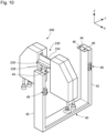
Figure 10 is a schematic diagram showing the storage unit of the present embodiment. - As shown in
Figure 3 , theconnection unit 230 includes abase unit 232 in a rectangular shape and a hangingunit 236. One end of thebase unit 232 is connected to the first extendinghand unit 210. The other end of thebase unit 232 is connected to the second extendinghand unit 220. As shown inFigure 8 , the extending sideremovable unit 240 is attached to a center of thesurface 233 of thebase unit 232. As shown inFigure 10 , the hangingunit 236 extends from arear surface 234 of thebase unit 232 so as to be orthogonal to thebase unit 232. Apositioning pin 238 is provided to the hangingunit 236. Theconnection unit 230 having such a configuration is configured to be able to be hanged from thestorage unit 40 of theworkpiece placement platform 20. - The extending
robot hand 200 having the above configuration is configured to lift up one end of the uppermost workpiece W from among the plurality of the workpieces W stacked on theworkpiece placement platform 20. Specifically, the extendingrobot hand 200 is configured to lift up the one end of the uppermost workpiece W by causing the respective suction units of thepermanent robot hand 100 and the extendingrobot hand 200 to suction the stacked workpiece in a state in which theair cylinder 130 and the air cylinder for lifting-up 150 of thepermanent robot hand 100 are expanded to the maximum, and by contracting thebuffer air cylinder 272 of the first extendinghand unit 210 after that. - It should be noted that the extending
robot hand 200 is not limited to the configuration described above, and various arbitrary shapes and configurations can be adopted. Further, various types of the extendingrobot hands 200 can be installed to and removed from theworkpiece supply robot 10. - The
workpiece supply robot 10 having the above configuration is configured to be able to hold the workpiece W stacked on theworkpiece placement platform 20 by thepermanent robot hand 100 and the extendingrobot hand 200 and supply the held workpiece W to the working machine or the like. Further, depending on a size, a shape, a holding position, and the like of the workpiece W to be held, theworkpiece supply robot 10 can hold the workpiece W only with thepermanent robot hand 100 or can hold the workpiece W by installing various types of the extending robot hands 200. - Furthermore, the
workpiece supply robot 10 is configured such that the respective air cylinders of thepermanent robot hand 100 and the respective spring-loaded shafts of the extendingrobot hand 200 independently expand and contract. With such a configuration, even when the workpiece W is stacked with an inclination, the workpiece W can be held as the respective air cylinders and the respective spring-loaded shafts expand and contract in accordance with the inclination. - Next, details of each component of the
workpiece placement platform 20 will be described. - As shown in
Figure 1 , theworkpiece placement platform 20 includes a plurality of (two in the present embodiment) theworkpiece placement units 30. Further, theworkpiece placement platform 20 includes thestorage unit 40 arranged in a gap between the plurality of theworkpiece placement units 30. It should be noted that since various publicly known configurations can be adopted to theworkpiece placement unit 30, detailed description thereof will be omitted. - As shown in
Figures 1 and10 , thestorage unit 40 includes asupport column 42 that extends in a direction intersecting with theworkpiece placement platform 20, and a hangingunit 44 that extends in a direction intersecting with an extending direction of thesupport column 42. In the present embodiment, thestorage unit 40 includes two sets of thesupport column 42 and the hangingunit 44, but the present invention is not limited to this. One set of thesupport column 42 and the hangingunit 44 may be provided, or three or more sets may be provided. -
Figure 11 is a side view showing the storage unit of the present embodiment. - As shown in
Figures 10 and11 , the hangingunit 44 is configured to be able to install and remove the extendingrobot hand 200 of theworkpiece supply robot 10. Specifically, the hangingunit 44 incudes apositioning hole 46. The hangingunit 44 is configured to be able to hang theconnection unit 230 of the extendingrobot hand 200 by inserting thepositioning pin 238 of the hangingunit 236 of theconnection unit 230 of the extendingrobot hand 200 into thepositioning hole 46. - The two
support columns 42 are provided so as to be spaced apart by a distance that allows thepermanent robot hand 100 of theworkpiece supply robot 10 to pass between thesupport columns 42 in a state in which the extendingrobot hand 200 of theworkpiece supply robot 10 is hanged from the hangingunit 44. - As shown in
Figures 10 and11 , thestorage unit 40 further includes aguide roller 48 attached to a side surface of thesupport column 42. With such a configuration, thestorage unit 40 makes it easy to install and remove the extendingrobot hand 200 and makes it possible to hang the extendingrobot hand 200 perpendicularly to theworkpiece placement platform 20. - The
storage unit 40 having the above configuration can hold the extendingrobot hand 200 such that a longitudinal direction of the extendingrobot hand 200 is aligned with a width direction of theworkpiece placement platform 20. Thereby, thestorage unit 40 can store the extendingrobot hand 200 in a limited space between theworkpiece placement units 30. - Next, a method of installing and removing the extending
robot hand 200 of theworkpiece supply robot 10 in the workpiece supply system 1 according to the present embodiment will be described. It should be noted that in the following description, it is assumed that the movement of theworkpiece supply robot 10 is controlled by thecore unit 90 of theworkpiece supply robot 10 unless otherwise specified. -
Figure 12 is a schematic diagram showing the workpiece supply system of the present embodiment. - First, in the
workpiece supply robot 10, thecarriage 80 moves in the Y-axis direction from a state shown inFigure 12 so as to carry thesupport arm 50 and thepermanent robot hand 100 to the gap between the twoworkpiece placement units 30 of theworkpiece placement platform 20. After the movement of thecarriage 80, thesupport arm 50 and thepermanent robot hand 100 rotate around the Z-axis such that the permanent sideremovable unit 110 provided to thesupport arm 50 is opposed to the extending sideremovable unit 240 of the extendingrobot hand 200 stored in thestorage unit 40 of theworkpiece placement platform 20. - Subsequently, in the
workpiece supply robot 10, themovable frame 70 moves in the X-axis direction so as to carry thesupport arm 50 and thepermanent robot hand 100 to a front of the extendingrobot hand 200 stored in thestorage unit 40 of theworkpiece placement platform 20. After that, theworkpiece supply robot 10 moves thecarriage 80 in the Y-axis direction and the Z-axis direction, thereby connecting the permanent sideremovable unit 110 provided to thesupport arm 50 to the extending sideremovable unit 240 of the extendingrobot hand 200. The extendingrobot hand 200 is installed to thesupport arm 50 when the permanent sideremovable unit 110 and the extending sideremovable unit 240 are connected. - After that, the
carriage 80 of theworkpiece supply robot 10 rises in the Z-axis direction, thereby thepositioning pin 238 of the hangingunit 236 of theconnection unit 230 of the extendingrobot hand 200, which is inserted into thepositioning hole 46 of the hangingunit 44 of thestorage unit 40 of theworkpiece placement platform 20, is pulled out. After thepositioning pin 238 is pulled out, in theworkpiece supply robot 10, themovable frame 70 moves in the X-axis direction again so that thesupport arm 50, thepermanent robot hand 100, and the extendingrobot hand 200 are carried from thestorage unit 40. By the above steps, an installing operation of the extendingrobot hand 200 of theworkpiece supply robot 10 in the workpiece supply system 1 is executed. Further, when the extendingrobot hand 200 is removed, a removing operation is executed in a reverse order of the steps described above. - As described above, the
workpiece supply robot 10 according to the present embodiment is configured to be able to transport the workpiece W placed on theworkpiece placement platform 20 from theworkpiece placement platform 20, and includes thesupport arm 50, thepermanent robot hand 100 fixedly provided to thesupport arm 50 and configured to hold the workpiece W, and the extendingrobot hand 200 configured to hold the workpiece W together with thepermanent robot hand 100, in which the extendingrobot hand 200 is configured to be removable. - Then, by including the extending
robot hand 200 configured to be removable in such a manner, theworkpiece supply robot 10 according to the present embodiment has an advantage that the robot hand can be partially extended without being subject to a restriction due to a common configuration of the robot hands. Further, theworkpiece supply robot 10 has an advantage that the extending part can be arbitrarily changed to suit the workpiece W. - Further, in the
workpiece supply robot 10 according to the present embodiment, thesupport arm 50 includes the permanent sideremovable unit 110 from which the extendingrobot hand 200 is removable, the extendingrobot hand 200 includes the extending sideremovable unit 240 capable of being connected to the permanent sideremovable unit 110, and the electric power is supplied from thepermanent robot hand 100 via the extending sideremovable unit 240. With such a configuration, theworkpiece supply robot 10 connects the extendingrobot hand 200 only with the extending sideremovable unit 240 so as to supply the electric power. Therefore, it is not necessary to connect extra wiring. As a result, theworkpiece supply robot 10 has an advantage that a downtime resulting from installation and removal of the extendingrobot hand 200 can be shortened. - Furthermore, in the
workpiece supply robot 10 according to the present embodiment, the permanent sideremovable unit 110 is provided to theside surface 52 of thesupport arm 50 and the extending sideremovable unit 240 is configured to be connected to the permanent sideremovable unit 110 from the horizontal direction. With such a configuration, in theworkpiece supply robot 10, the permanent sideremovable unit 110 and the extending sideremovable unit 240 are less likely to collect dust, which improves robustness of the permanent sideremovable unit 110 and the extending sideremovable unit 240. As a result, theworkpiece supply robot 10 has an advantage that trouble resulting from the installation and removal of the extendingrobot hand 200 can be reduced. - Further, in the
workpiece supply robot 10 according to the present embodiment, the extendingrobot hand 200 further includes the first extendinghand unit 210 and the second extendinghand unit 220 that are opposed to each other with thepermanent robot hand 100 therebetween and theconnection unit 230 configured to connect the first extendinghand unit 210 and the second extendinghand unit 220, and the extending sideremovable unit 240 is provided to theconnection unit 230. With such a configuration, theworkpiece supply robot 10 has an advantage that the robot hand can be extended to the left and right of thepermanent robot hand 100 with one removable unit. - Furthermore, in the
workpiece supply robot 10 according to the present embodiment, the extendingrobot hand 200 is arranged substantially in a bilaterally symmetrical manner with the extending sideremovable unit 240 as the center. With such a configuration, theworkpiece supply robot 10 has an advantage that the robot hand can be extended in a bilaterally symmetrical manner and the holding position of the workpiece W is not restricted by the arrangement of the extendingrobot hand 200. - Further, in the
workpiece supply robot 10 according to the present embodiment, thepermanent robot hand 100 includes thesurface detection unit 170, and thesurface detection unit 170 is configured to be able to detect the surface of the workpiece W. With such a configuration, theworkpiece supply robot 10 has an advantage that the surface of the workpiece W can be detected regardless of whether or not the extendingrobot hand 200 is installed. Further, in theworkpiece supply robot 10, it is possible to reduce a cost by mounting thesurface detection unit 170 on thepermanent robot hand 100 and keeping a function of the extendingrobot hand 200 side at a minimum necessary level. - Furthermore, in the
workpiece supply robot 10 according to the present embodiment, thepermanent robot hand 100 includes thematerial detection unit 180, and thematerial detection unit 180 is configured to be able to detect whether or not the workpiece W is placed on theworkpiece placement platform 20. With such a configuration, theworkpiece supply robot 10 has an advantage that whether or not the workpiece W is placed on the workpiece placement platform can be detected regardless of whether or not the extendingrobot hand 200 is installed. Further, in theworkpiece supply robot 10, it is possible to reduce the cost by mounting thematerial detection unit 180 on thepermanent robot hand 100 and keeping the function of the extendingrobot hand 200 side at the minimum necessary level. - Further, in the
workpiece supply robot 10 according to the present embodiment, thepermanent robot hand 100 is configured to lift up the one end of the uppermost workpiece W from among the plurality of the workpieces W stacked on theworkpiece placement platform 20. With such a configuration, theworkpiece supply robot 10 has an advantage that the one end of the uppermost workpiece W can be lifted up regardless of whether or not the extendingrobot hand 200 is installed. - Furthermore, in the
workpiece supply robot 10 according to the present embodiment, the extendingrobot hand 200 is configured to lift up the one end of the uppermost workpiece W from among the plurality of the workpieces W stacked on theworkpiece placement platform 20. With such a configuration, theworkpiece supply robot 10 has an advantage that an end of the large workpiece W can be lifted up when the extendingrobot hand 200 is installed to hold the large workpiece W. - The workpiece supply system 1 according to the present embodiment includes the
workpiece supply robot 10 described above and theworkpiece placement platform 20, and theworkpiece placement platform 20 includes thestorage unit 40 for storing the extendingrobot hand 200. With such a configuration, theworkpiece supply robot 10 has an advantage that there is no need to make a movable range of theworkpiece supply robot 10 larger than that of a conventional one because it is possible to install and remove the extendingrobot hand 200 on theworkpiece placement platform 20. Further, theworkpiece supply robot 10 has an advantage that the extendingrobot hand 200 can be installed and removed in a working space that is not different from the conventional one. - Further, in the workpiece supply system 1 according to the present embodiment, the
workpiece placement platform 20 includes the plurality of theworkpiece placement units 30, and thestorage unit 40 is arranged in the gap between the plurality of theworkpiece placement units 30. With such a configuration, theworkpiece supply robot 10 has an advantage that theworkpiece placement platform 20 can be prevented from becoming large. - Furthermore, in the workpiece supply system 1 according to the present embodiment, the
storage unit 40 includes thesupport column 42 that extends in the direction intersecting with theworkpiece placement platform 20 and the hangingunit 44 that extends in the direction intersecting with the extending direction of thesupport column 42. With such a configuration, theworkpiece supply robot 10 has an advantage that thestorage unit 40 can be made smaller as it is possible to hang the extendingrobot hand 200 for storage. - Further, in the workpiece supply system 1 according to the present embodiment, the hanging
unit 44 is configured to be able to hang theconnection unit 230 of the extendingrobot hand 200. With such a configuration, theworkpiece supply robot 10 has an advantage that it is possible to store the extendingrobot hand 200 in a simple configuration and that it takes less time to install and remove the extendingrobot hand 200 to and from thestorage unit 40 because the extendingrobot hand 200 is hanged only by theconnection unit 230. - Although the preferred embodiment of the present invention has been described above, the technical scope of the present invention is not limited to the scope described in the embodiment described above. Various modifications or improvements can be added to the embodiment described above.
- For example, in the embodiment described above, it has been described that the
support arm 50 includes the permanent sideremovable unit 110 from which the extendingrobot hand 200 is removable, the extendingrobot hand 200 includes the extending sideremovable unit 240 capable of being connected to the permanent sideremovable unit 110, and the electric power is supplied from thepermanent robot hand 100 via the extending sideremovable unit 240. However, the present invention is not limited to this. Various arbitrary configurations can be adopted as long as the extendingrobot hand 200 is configured to be removable. Further, the extendingrobot hand 200 may be configured to be removable between thesupport arm 50 and thepermanent robot hand 100. Furthermore, the extendingrobot hand 200 may be configured to be removable from thepermanent robot hand 100. Further, the extendingrobot hand 200 may be configured to be removable from thecore unit 90. - In the embodiment described above, it has been described that the permanent side
removable unit 110 is provided to theside surface 52 of thesupport arm 50 and the extending sideremovable unit 240 is connected to the permanent sideremovable unit 110 from the horizontal direction. However, the present invention is not limited to this. For example, the permanent sideremovable unit 110 may be provided on a bottom surface of thesupport arm 50. Further, the extending sideremovable unit 240 may be configured to be connected to the permanent sideremovable unit 110 from the vertical direction. - In the embodiment described above, it has been described that the extending
robot hand 200 further includes the first extendinghand unit 210 and the second extendinghand unit 220, which are opposed to each other with thepermanent robot hand 100 therebetween, and theconnection unit 230 configured to connect the first extendinghand unit 210 and the second extendinghand unit 220, and the extending sideremovable unit 240 is provided to theconnection unit 230. However, the present invention is not limited to this. For example, various arbitrary configurations can be adopted such as the one in which the extendingrobot hand 200 includes one extending hand unit and the extending sideremovable unit 240 is provided to the extending hand unit. - In the embodiment described above, the extending
robot hand 200 has been described as the one being arranged substantially in a bilaterally symmetrical manner with the extending sideremovable unit 240 as the center. However, the present invention is not limited to this. For example, the extendingrobot hand 200 may be arranged in a bilaterally asymmetrical manner with respect to the extending sideremovable unit 240. - In the embodiment described above, it has been described that the
permanent robot hand 100 includes thesurface detection unit 170 and thesurface detection unit 170 is configured to be able to detect the surface of the workpiece W. However, the present invention is not limited to this. Thepermanent robot hand 100 may not include thesurface detection unit 170. - In the embodiment described above, it has been described that the
permanent robot hand 100 includes thematerial detection unit 180 and thematerial detection unit 180 is configured to be able to detect whether or not the workpiece W is placed on theworkpiece placement platform 20. However, the present invention is not limited to this. Thepermanent robot hand 100 may not include thematerial detection unit 180. - In the embodiment described above, it has been described that the
permanent robot hand 100 is configured to lift up the one end of the uppermost workpiece W from among the plurality of the workpieces W stacked on theworkpiece placement platform 20. However, the present invention is not limited to this. Thepermanent robot hand 100 may not be configured to lift up the one end of the uppermost workpiece W from among the plurality of the workpieces W stacked on theworkpiece placement platform 20. - In the embodiment described above, the extending
robot hand 200 has been described as the one configured to lift up the one end of the uppermost workpiece W from among the plurality of the workpieces W stacked on theworkpiece placement platform 20. However, the present invention is not limited to this. The extendingrobot hand 200 may not be configured to lift up the one end of the uppermost workpiece W from among the plurality of the workpieces W stacked on theworkpiece placement platform 20. - In the embodiment described above, it has been described that the
workpiece placement platform 20 includes the plurality of theworkpiece placement units 30 and thestorage unit 40 is arranged in the gap between the plurality of theworkpiece placement units 30. However, the present invention is not limited to this. Various arbitrary configurations can be adopted such as the one in which thestorage unit 40 is provided adjacent to an outside of theworkpiece placement unit 30. - In the embodiment described above, the
storage unit 40 has been described as the one including thesupport column 42 that extends in the direction intersecting with theworkpiece placement platform 20 and the hangingunit 44 that extends in the direction intersecting with the extending direction of thesupport column 42. However, the present invention is not limited to this. Various arbitrary configurations can be adopted as long as thestorage unit 40 is configured to be able to store the extendingrobot hand 200. For example, thestorage unit 40 may be a wall surface or a floor board. - In the embodiment described above, the hanging
unit 44 has been described as the one configured to be able to hang theconnection unit 230 of the extendingrobot hand 200. However, the present invention is not limited to this. For example, the hangingunit 44 may be configured to be able to hang the first extendinghand unit 210 or the second extendinghand unit 220 of the extendingrobot hand 200. - In the embodiment described above, the
workpiece supply robot 10 has been described on the assumption that it is a gantry type robot. However, the present invention is not limited to this. Theworkpiece supply robot 10 may be, for example, a six-axis articulated robot or the like. If theworkpiece supply robot 10 is the six-axis articulated robot, thesupport arm 50 corresponds to an arm unit that constitutes a robot arm of the six-axis articulated robot. - In the embodiment described above, the
suction pad 142 of thesuction unit 140 and the suction pad for lifting-up 162 of the suction unit for lifting-up 160 of thepermanent robot hand 100 have been described as different suction pads. However, the present invention is not limited to this. Thesuction pad 142 and the suction pad for lifting-up 162 may be the same suction pad. In a similar manner, thesuction pad 252 of thesuction unit 250 and the suction pad for lifting-up 262 of the suction unit for lifting-up 260 of the extendingrobot hand 200 may be the same suction pad. - In the embodiment described above, the second extending
hand unit 220 of the extendingrobot hand 200 has been described as having a different configuration from the first extendinghand unit 210 thereof. However, the present invention is not limited to this. The second extendinghand unit 220 may have the same configuration as the first extendinghand unit 210. - The
air cylinder 130 and the air cylinder for lifting-up 150 of thepermanent robot hand 100 and thebuffer air cylinder 272 of the extendingrobot hand 200 have been described as the single-acting air cylinders. However, the present invention is not limited to this. These air cylinders may be, for example, double-acting air cylinders. -
- 1
- Workpiece supply system
- 10
- Workpiece supply robot
- 20
- Workpiece placement platform
- 30
- Workpiece placement unit
- 40
- Storage unit
- 42
- Support column
- 44
- Hanging unit
- 46
- Positioning hole
- 48
- Guide roller
- 50
- Support arm
- 52
- Side surface of support arm
- 60
- Base frame
- 62
- First frame unit
- 64
- Second frame unit
- 70
- Movable frame
- 72
- Third frame unit
- 74
- Fourth frame unit
- 80
- Carriage
- 90
- Core unit
- 100
- Permanent robot hand
- 102
- Permanent cover
- 110
- Permanent side removable unit
- 112
- Permanent side pedestal
- 114
- Convex type connection unit
- 120
- Permanent hand unit
- 130
- Air cylinder
- 132
- Piston rod
- 134
- Cylinder tube
- 136
- Head cover
- 136a
- Rectangular portion
- 136b
- Cylindrical portion
- 140
- Suction unit
- 142
- Suction pad
- 150
- Air cylinder for lifting-up
- 152
- Piston rod for lifting-up
- 154
- Cylinder tube for lifting-up
- 156
- Head cover for lifting-up
- 156a
- Rectangular portion
- 156b
- Cylindrical portion
- 160
- Suction unit for lifting-up
- 162
- Suction pad for lifting-up
- 170
- Surface detection unit
- 180
- Material detection unit
- 190
- Stroke control mechanism
- 200
- Extending robot hand
- 210
- First extending hand unit
- 212
- First extending hand cover
- 220
- Second extending hand unit
- 222
- Second extending hand cover
- 230
- Connection unit
- 232
- Base unit
- 233
- Surface of base unit
- 234
- Rear surface of base unit
- 236
- Hanging unit
- 238
- Positioning pin
- 240
- Extending side removable unit
- 242
- Extending side pedestal
- 244
- Concave type connection unit
- 250
- Suction unit
- 252
- Suction pad
- 260
- Suction unit for lifting-up
- 262
- Suction pad for lifting-up
- 270
- Buffer mechanism
- 272
- Buffer air cylinder
- 276
- Connection fitting
- 280
- Spring-loaded shaft
- 282
- Shaft unit
- 284
- Spring unit
- 290
- Spring-loaded shaft for lifting-up
- 292
- Shaft unit
- 294
- Spring unit
- W
- Workpiece
Claims (13)
- A workpiece supply robot comprising:a support arm;a permanent robot hand fixedly provided to the support arm, and configured to hold a workpiece placed on a workpiece placement platform; andan extending robot hand configured to hold the workpiece together with the permanent robot hand, whereinthe workpiece supply robot is configured to be able to transport the workpiece from the workpiece placement platform, andthe extending robot hand is configured to be removable.
- The workpiece supply robot according to claim 1, whereinthe support arm includes a permanent side removable unit from which the extending robot hand is removable,the extending robot hand includes an extending side removable unit capable of being connected to the permanent side removable unit, andelectric power is supplied from the permanent robot hand via the extending side removable unit.
- The workpiece supply robot according to claim 2, whereinthe permanent side removable unit is provided to a side surface of the support arm, andthe extending side removable unit is connected to the permanent side removable unit from a horizontal direction.
- The workpiece supply robot according to claim 2 or 3, wherein
the extending robot hand further includes:a first extending hand unit and a second extending hand unit opposed to each other with the permanent robot hand between the first extending hand unit and the second extending hand unit; anda connection unit configured to connect the first extending hand unit and the second extending hand unit, andthe extending side removable unit is provided to the connection unit. - The workpiece supply robot according to any one of claims 2 to 4, wherein the extending robot hand is arranged in a bilaterally symmetrical manner with the extending side removable unit as a center.
- The workpiece supply robot according to any one of claims 1 to 5, whereinthe permanent robot hand includes a surface detection unit, andthe surface detection unit is configured to be able to detect a surface of the workpiece.
- The workpiece supply robot according to any one of claims 1 to 6, whereinthe permanent robot hand includes a material detection unit, andthe material detection unit is configured to be able to detect whether or not the workpiece is placed on the workpiece placement platform.
- The workpiece supply robot according to any one of claims 1 to 7, wherein the permanent robot hand is configured to lift up one end of an uppermost workpiece from among a plurality of the workpieces stacked on the workpiece placement platform.
- The workpiece supply robot according to any one of claims 1 to 8, wherein the extending robot hand is configured to lift up one end of an uppermost workpiece from among the plurality of the workpieces stacked on the workpiece placement platform.
- A workpiece supply system comprising:a workpiece supply robot according to any one of claims 1 to 9; anda workpiece placement platform, whereinthe workpiece placement platform includes a storage unit for storing the extending robot hand.
- The workpiece supply system according to claim 10, whereinthe workpiece placement platform includes a plurality of workpiece placement units, andthe storage unit is arranged in a gap between the plurality of the workpiece placement units.
- The workpiece supply system according to claim 10 or 11, wherein the storage unit includes:a support column extending in a direction intersecting with the workpiece placement platform; anda hanging unit extending in a direction intersecting with an extending direction of the support column.
- The workpiece supply system according to claim 12, wherein
the extending robot hand further includes:a first extending hand unit and a second extending hand unit opposed to each other with the permanent robot hand between the first extending hand unit and the second extending hand unit; anda connection unit configured to connect the first extending hand unit and the second extending hand unit;the extending side removable unit is provided to the connection unit, andthe hanging unit is configured to be able to hang the connection unit of the extending robot hand.
Applications Claiming Priority (2)
| Application Number | Priority Date | Filing Date | Title |
|---|---|---|---|
| JP2021141211A JP7588053B2 (en) | 2021-08-31 | 2021-08-31 | Work supply robot and work supply system |
| PCT/JP2022/030529 WO2023032621A1 (en) | 2021-08-31 | 2022-08-10 | Workpiece supply robot and workpiece supply system |
Publications (2)
| Publication Number | Publication Date |
|---|---|
| EP4397457A1 true EP4397457A1 (en) | 2024-07-10 |
| EP4397457A4 EP4397457A4 (en) | 2024-07-17 |
Family
ID=85412250
Family Applications (1)
| Application Number | Title | Priority Date | Filing Date |
|---|---|---|---|
| EP22864206.2A Pending EP4397457A4 (en) | 2021-08-31 | 2022-08-10 | Workpiece supply robot and workpiece supply system |
Country Status (4)
| Country | Link |
|---|---|
| US (1) | US20240424692A1 (en) |
| EP (1) | EP4397457A4 (en) |
| JP (1) | JP7588053B2 (en) |
| WO (1) | WO2023032621A1 (en) |
Families Citing this family (1)
| Publication number | Priority date | Publication date | Assignee | Title |
|---|---|---|---|---|
| US20240353815A1 (en) * | 2023-04-21 | 2024-10-24 | GM Global Technology Operations LLC | System and method for locally re-shaping a workpiece |
Family Cites Families (15)
| Publication number | Priority date | Publication date | Assignee | Title |
|---|---|---|---|---|
| DE3320762C2 (en) * | 1983-06-09 | 1994-10-27 | Trumpf Gmbh & Co | Punching machine with a stationary magazine |
| JPH08112620A (en) | 1994-10-17 | 1996-05-07 | Amada Co Ltd | Gripper die managing method in bending robot automatic changing device |
| JP2004160567A (en) * | 2002-11-11 | 2004-06-10 | Fanuc Ltd | Article taking-out device |
| DE102005009734B4 (en) * | 2004-03-19 | 2016-10-13 | Trumpf Werkzeugmaschinen Gmbh + Co. Kg | Machine handling device, sucker arrangement for this and suction units of a suction arrangement |
| JP2007222971A (en) * | 2006-02-22 | 2007-09-06 | Nissan Motor Co Ltd | Robot hand and robot hand finger changer |
| DE102011075625B4 (en) * | 2011-05-11 | 2021-08-26 | J. Schmalz Gmbh | Device for gripping and holding workpieces by means of negative pressure |
| JP2015071207A (en) * | 2013-10-03 | 2015-04-16 | 株式会社豊田自動織機 | Robot hand and control method thereof |
| EP3636392B1 (en) * | 2015-06-11 | 2022-11-02 | Soft Robotics, Inc. | Modular robotic systems |
| IT201700031823A1 (en) * | 2017-03-22 | 2018-09-22 | Schnell Spa | EQUIPMENT FOR MANIPULATING PRODUCTS AND AUTOMATIC ADJUSTMENT METHOD OF THE SAME EQUIPMENT |
| JP6702909B2 (en) * | 2017-04-12 | 2020-06-03 | ファナック株式会社 | Robot system |
| US20190111575A1 (en) * | 2017-10-18 | 2019-04-18 | Canon Kabushiki Kaisha | Tool stocker, interchangeable tool, robot apparatus, robot system, control method of robot system, and storage medium |
| KR101848215B1 (en) * | 2017-11-30 | 2018-04-11 | 주식회사 에이비비코리아 | Tool loading device for arm of robot |
| JP6564912B1 (en) * | 2018-06-14 | 2019-08-21 | 株式会社アマダホールディングス | Work transfer device and single-sheet taking unit |
| IT201800009542A1 (en) * | 2018-10-17 | 2020-04-17 | Astes4 Sa | PERFECTED TOOL AND SYSTEM FOR A MANIPULATOR IN SHEET METAL CUTTING CENTERS |
| JP2020203350A (en) * | 2019-06-18 | 2020-12-24 | 株式会社東芝 | Cargo handling device and tool stand |
-
2021
- 2021-08-31 JP JP2021141211A patent/JP7588053B2/en active Active
-
2022
- 2022-08-10 US US18/682,501 patent/US20240424692A1/en active Pending
- 2022-08-10 WO PCT/JP2022/030529 patent/WO2023032621A1/en not_active Ceased
- 2022-08-10 EP EP22864206.2A patent/EP4397457A4/en active Pending
Also Published As
| Publication number | Publication date |
|---|---|
| US20240424692A1 (en) | 2024-12-26 |
| JP2023034796A (en) | 2023-03-13 |
| EP4397457A4 (en) | 2024-07-17 |
| WO2023032621A1 (en) | 2023-03-09 |
| JP7588053B2 (en) | 2024-11-21 |
Similar Documents
| Publication | Publication Date | Title |
|---|---|---|
| JP6591558B2 (en) | Stacking line system and method for stacking blanks produced from blanking shears or blanking presses | |
| JP5912474B2 (en) | Robot hand device | |
| US20240424692A1 (en) | Workpiece supply robot and workpiece supply system | |
| JP2020044617A (en) | Processing system | |
| JP6564912B1 (en) | Work transfer device and single-sheet taking unit | |
| TWI709467B (en) | Transport system and its operating method | |
| CN107381023B (en) | Multidirectional material transfer device | |
| CN114080281A (en) | Vacuum gripper and method for adsorbing and holding workpiece | |
| JP5622456B2 (en) | Hand attachment / detachment mechanism in workpiece transfer device | |
| JP2017170586A (en) | End effector, robot and robot control device | |
| WO2022113975A1 (en) | Robot and article-dimension acquisition method | |
| JPH11179692A (en) | Industrial robot hand abnormality detection device and hand abnormality detection method | |
| JP6677710B2 (en) | Blank loading on punching press line | |
| CN221092707U (en) | A gripping manipulator and handling system | |
| CN111170005A (en) | Loading and unloading device | |
| CN117325199A (en) | Grabbing mechanical arm and carrying system | |
| CN223849261U (en) | A multi-functional mechanical gripper | |
| US10730706B2 (en) | Hand for connector connection and hand system | |
| JP7264241B2 (en) | Sensor body and adsorption device | |
| CN219791735U (en) | Stacker crane handle device | |
| JP2019126858A (en) | Transportation device and operation method thereof | |
| CN117105001B (en) | Line-aligning equipment | |
| CN217475969U (en) | Paw device | |
| CN210996164U (en) | Split type double-material warehouse | |
| CN216759932U (en) | Robot vision guide chip absorbs and holds device in hand |
Legal Events
| Date | Code | Title | Description |
|---|---|---|---|
| STAA | Information on the status of an ep patent application or granted ep patent |
Free format text: STATUS: THE INTERNATIONAL PUBLICATION HAS BEEN MADE |
|
| PUAI | Public reference made under article 153(3) epc to a published international application that has entered the european phase |
Free format text: ORIGINAL CODE: 0009012 |
|
| STAA | Information on the status of an ep patent application or granted ep patent |
Free format text: STATUS: REQUEST FOR EXAMINATION WAS MADE |
|
| 17P | Request for examination filed |
Effective date: 20240328 |
|
| AK | Designated contracting states |
Kind code of ref document: A1 Designated state(s): AL AT BE BG CH CY CZ DE DK EE ES FI FR GB GR HR HU IE IS IT LI LT LU LV MC MK MT NL NO PL PT RO RS SE SI SK SM TR |
|
| A4 | Supplementary search report drawn up and despatched |
Effective date: 20240619 |
|
| RIC1 | Information provided on ipc code assigned before grant |
Ipc: B25J 15/00 20060101ALI20240613BHEP Ipc: B25J 15/04 20060101AFI20240613BHEP |
|
| DAV | Request for validation of the european patent (deleted) | ||
| DAX | Request for extension of the european patent (deleted) | ||
| STAA | Information on the status of an ep patent application or granted ep patent |
Free format text: STATUS: EXAMINATION IS IN PROGRESS |
|
| 17Q | First examination report despatched |
Effective date: 20250205 |