EP4397430A1 - Laser welding device - Google Patents
Laser welding device Download PDFInfo
- Publication number
- EP4397430A1 EP4397430A1 EP22884065.8A EP22884065A EP4397430A1 EP 4397430 A1 EP4397430 A1 EP 4397430A1 EP 22884065 A EP22884065 A EP 22884065A EP 4397430 A1 EP4397430 A1 EP 4397430A1
- Authority
- EP
- European Patent Office
- Prior art keywords
- coupling
- upper mask
- hole
- base plate
- coupled
- Prior art date
- Legal status (The legal status is an assumption and is not a legal conclusion. Google has not performed a legal analysis and makes no representation as to the accuracy of the status listed.)
- Pending
Links
Images



Classifications
-
- B—PERFORMING OPERATIONS; TRANSPORTING
- B23—MACHINE TOOLS; METAL-WORKING NOT OTHERWISE PROVIDED FOR
- B23K—SOLDERING OR UNSOLDERING; WELDING; CLADDING OR PLATING BY SOLDERING OR WELDING; CUTTING BY APPLYING HEAT LOCALLY, e.g. FLAME CUTTING; WORKING BY LASER BEAM
- B23K26/00—Working by laser beam, e.g. welding, cutting or boring
- B23K26/14—Working by laser beam, e.g. welding, cutting or boring using a fluid stream, e.g. a jet of gas, in conjunction with the laser beam; Nozzles therefor
-
- B—PERFORMING OPERATIONS; TRANSPORTING
- B23—MACHINE TOOLS; METAL-WORKING NOT OTHERWISE PROVIDED FOR
- B23K—SOLDERING OR UNSOLDERING; WELDING; CLADDING OR PLATING BY SOLDERING OR WELDING; CUTTING BY APPLYING HEAT LOCALLY, e.g. FLAME CUTTING; WORKING BY LASER BEAM
- B23K26/00—Working by laser beam, e.g. welding, cutting or boring
- B23K26/20—Bonding
- B23K26/21—Bonding by welding
-
- B—PERFORMING OPERATIONS; TRANSPORTING
- B23—MACHINE TOOLS; METAL-WORKING NOT OTHERWISE PROVIDED FOR
- B23K—SOLDERING OR UNSOLDERING; WELDING; CLADDING OR PLATING BY SOLDERING OR WELDING; CUTTING BY APPLYING HEAT LOCALLY, e.g. FLAME CUTTING; WORKING BY LASER BEAM
- B23K26/00—Working by laser beam, e.g. welding, cutting or boring
- B23K26/20—Bonding
- B23K26/21—Bonding by welding
- B23K26/22—Spot welding
-
- B—PERFORMING OPERATIONS; TRANSPORTING
- B23—MACHINE TOOLS; METAL-WORKING NOT OTHERWISE PROVIDED FOR
- B23K—SOLDERING OR UNSOLDERING; WELDING; CLADDING OR PLATING BY SOLDERING OR WELDING; CUTTING BY APPLYING HEAT LOCALLY, e.g. FLAME CUTTING; WORKING BY LASER BEAM
- B23K37/00—Auxiliary devices or processes, not specially adapted for a procedure covered by only one of the other main groups of this subclass
- B23K37/04—Auxiliary devices or processes, not specially adapted for a procedure covered by only one of the other main groups of this subclass for holding or positioning work
-
- B—PERFORMING OPERATIONS; TRANSPORTING
- B23—MACHINE TOOLS; METAL-WORKING NOT OTHERWISE PROVIDED FOR
- B23K—SOLDERING OR UNSOLDERING; WELDING; CLADDING OR PLATING BY SOLDERING OR WELDING; CUTTING BY APPLYING HEAT LOCALLY, e.g. FLAME CUTTING; WORKING BY LASER BEAM
- B23K37/00—Auxiliary devices or processes, not specially adapted for a procedure covered by only one of the other main groups of this subclass
- B23K37/04—Auxiliary devices or processes, not specially adapted for a procedure covered by only one of the other main groups of this subclass for holding or positioning work
- B23K37/0426—Fixtures for other work
- B23K37/0435—Clamps
- B23K37/0443—Jigs
-
- B—PERFORMING OPERATIONS; TRANSPORTING
- B23—MACHINE TOOLS; METAL-WORKING NOT OTHERWISE PROVIDED FOR
- B23K—SOLDERING OR UNSOLDERING; WELDING; CLADDING OR PLATING BY SOLDERING OR WELDING; CUTTING BY APPLYING HEAT LOCALLY, e.g. FLAME CUTTING; WORKING BY LASER BEAM
- B23K2101/00—Articles made by soldering, welding or cutting
- B23K2101/36—Electric or electronic devices
- B23K2101/38—Conductors
-
- F—MECHANICAL ENGINEERING; LIGHTING; HEATING; WEAPONS; BLASTING
- F16—ENGINEERING ELEMENTS AND UNITS; GENERAL MEASURES FOR PRODUCING AND MAINTAINING EFFECTIVE FUNCTIONING OF MACHINES OR INSTALLATIONS; THERMAL INSULATION IN GENERAL
- F16B—DEVICES FOR FASTENING OR SECURING CONSTRUCTIONAL ELEMENTS OR MACHINE PARTS TOGETHER, e.g. NAILS, BOLTS, CIRCLIPS, CLAMPS, CLIPS OR WEDGES; JOINTS OR JOINTING
- F16B21/00—Means for preventing relative axial movement of a pin, spigot, shaft or the like and a member surrounding it; Stud-and-socket releasable fastenings
- F16B21/10—Means for preventing relative axial movement of a pin, spigot, shaft or the like and a member surrounding it; Stud-and-socket releasable fastenings by separate parts
- F16B21/16—Means for preventing relative axial movement of a pin, spigot, shaft or the like and a member surrounding it; Stud-and-socket releasable fastenings by separate parts with grooves or notches in the pin or shaft
- F16B21/165—Means for preventing relative axial movement of a pin, spigot, shaft or the like and a member surrounding it; Stud-and-socket releasable fastenings by separate parts with grooves or notches in the pin or shaft with balls or rollers
-
- Y—GENERAL TAGGING OF NEW TECHNOLOGICAL DEVELOPMENTS; GENERAL TAGGING OF CROSS-SECTIONAL TECHNOLOGIES SPANNING OVER SEVERAL SECTIONS OF THE IPC; TECHNICAL SUBJECTS COVERED BY FORMER USPC CROSS-REFERENCE ART COLLECTIONS [XRACs] AND DIGESTS
- Y02—TECHNOLOGIES OR APPLICATIONS FOR MITIGATION OR ADAPTATION AGAINST CLIMATE CHANGE
- Y02E—REDUCTION OF GREENHOUSE GAS [GHG] EMISSIONS, RELATED TO ENERGY GENERATION, TRANSMISSION OR DISTRIBUTION
- Y02E60/00—Enabling technologies; Technologies with a potential or indirect contribution to GHG emissions mitigation
- Y02E60/10—Energy storage using batteries
Definitions
- the present invention relates to a laser welding device that welds an electrode tab extending from an electrode assembly to an electrode lead having one end extending outside a pouch and the other end disposed inside the pouch when manufacturing a secondary battery, and more particularly, to a laser welding device, in which an upper mask is improved in convenience of replacement.
- such a secondary battery has a structure comprising an electrode assembly having a structure in which electrodes (a negative electrode and a positive electrode) and a separator are alternately laminated, an electrolyte allowing ions to move to the electrodes, and a case in which the electrode assembly and the electrolyte are accommodated.
- the lithium secondary battery may be manufactured in various shapes.
- the lithium secondary battery may be manufactured in a cylinder type, a prismatic type, or a pouch type.
- the electrode lead in a state in which the electrode lead and the electrode tab are welded to each other, the electrode lead has one side connected to the electrode tab within the pouch and the other side protruding to the outside the pouch so as to be electrically connected to an external device.
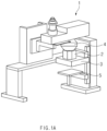
- the electrode lead and the electrode tab are welded through a laser welding device 1 as illustrated in FIG. 1a .
- the laser irradiated from the laser irradiator 4 irradiates through an opening hole 2c of the base plate 2 and an opening hole 3d of the upper mask 3 so that the welding is performed. That is, an upper end 3e of the opening hole 3d of the upper mask 3 communicates with the opening hole 2c of the base plate 2.
- the upper mask 3 has a shape that is gradually narrowed toward a lower end thereof, and a lower end 3f of the opening hole 3d is disposed above a welding point W of the electrode lead L and the electrode tab T.
- the upper mask may include a hollow cone shaped portion that is pointed to be gathered at an end thereof so that the opening hole through which the laser passes communicates at the end that is pointed to be gathered, and the gas passage may be formed to be continued to the opening hole.
- the gas passage may be formed to be continued from the inside of a shape surface that forms a shape of the upper mask.
- FIG. 2 is a view illustrating a shape (above) in which the upper mask 30 according to the present invention is separated and a state (below) in which the base plate 20 according to the present invention is disposed upside down so that a bottom surface that is in contact with the upper mask 30 is shown.
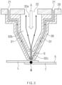
- FIG. 3 is a cross-sectional view illustrating a portion having a hollow cone shape when the upper mask 30 and the base plate 20 according to the present invention are coupled to each other.
- a portion at which the coupling tool 10 is coupled to the coupling hole is omitted in FIG. 3 as a point disposed outside in FIG. 3 .
- the upper mask 30 is provided with a portion that is formed in the form of a hollow cone shape that is pointed to be gathered at an end thereof, and thus, opening holes 32a, 32b, and 32c into which the laser is irradiated may be formed to communicate with each other at the end at which the opening holes 32a, 32b, and 32c are pointed to be gathered toward a point W to be welded, and a gas passage 31 is also connected to a lower end 32c of the opening holes 32a, 32b, and 32c.
- the external tube or hose H is connected to one side of the injection hole 21 formed in the base plate 20, and when the upper mask 30 is coupled to the base plate, the other side of the injection hole 21 communicates with the gas passage 31 of the upper mask 30.
- the cylinder 11 has a hollow shape in a longitudinal direction, and an air hole 12 is punched at a predetermined height.
- the air hole 12 allows the inside and outside of the cylinder 11 to communicate with each other.
- the piston 13 has a diameter that gradually increases downward in FIG. 4 .
- the ball 15 is pressed by the piston 13 to protrude outward from the surface of the cylinder 11.
- the coupling hole is provided in the upper mask 30 so that the coupling tools 10 enter according to positions at which the coupling tools 10 are disposed, and a groove having a concave shape is formed in an inner circumferential surface of the coupling hole.
- the coupling hole and the groove may be integrally formed in the upper mask 30, but the sleeve 40 provided with the coupling hole 41 and the groove 42 may be provided in a shape coupled to the upper mask 30.
- FIG. 5 is a view illustrating a state in which the coupling hole 41 and the groove 42 are provided in a ringshaped sleeve 40 that is separately coupled to the upper mask 30, and the coupling tool 10 is coupled to the sleeve 40.
- the coupling tool 10 when the coupling tool 10 enters the coupling hole 41, the ball 15 enters the groove 42 formed in an inner circumferential surface of the coupling hole 41 by the piston 13 so that the coupling tool 10 is restricted to the sleeve 40.
- the coupling tool 10 since the coupling tool 10 is coupled to the base plate 20 and the sleeve 40 is fixed to the upper mask 30, the base plate 20 and the upper mast 30 are coupled to each other. That is, the coupling tool 10 fixed to the base plate 20 may be fitted into the coupling hole 41, and thus, the base plate 20 and the upper mask 30 may be coupled to each other in a one-touch manner.
- the base plate 20 is provided with at least two or more coupling tools 10, and the upper mask 30 has a plurality of coupling holes, which correspond to the number of coupling tools 10.
- the plurality of balls 15 are disposed along the circumference of the cylinder 11 so that the coupling tool 10 is restricted more efficiently.
Landscapes
- Engineering & Computer Science (AREA)
- Physics & Mathematics (AREA)
- Optics & Photonics (AREA)
- Mechanical Engineering (AREA)
- Plasma & Fusion (AREA)
- General Engineering & Computer Science (AREA)
- Laser Beam Processing (AREA)
- Connection Of Batteries Or Terminals (AREA)
Abstract
Description
- The present application claims the benefit of the priority of
Korean Patent Application No. 10-2021-0140231, filed on October 20, 2021 - The present invention relates to a laser welding device that welds an electrode tab extending from an electrode assembly to an electrode lead having one end extending outside a pouch and the other end disposed inside the pouch when manufacturing a secondary battery, and more particularly, to a laser welding device, in which an upper mask is improved in convenience of replacement.
- Lithium secondary batteries that are chargeable/dischargeable and lightweight and have high output densities are being widely used as energy sources for various devices.
- In addition, lithium secondary batteries have attracted considerable attention as power sources for hybrid electric vehicles (HEVs), plug-in hybrid electric vehicles (PHEVs), battery electric vehicles (BEVs), and electric vehicles (EVs), which have been developed to solve limitations, such as air pollution and green-house gases, caused by existing internal-combustion engine vehicles that use fossil fuels, such as, gasoline and diesel vehicles.
- In general, such a secondary battery has a structure comprising an electrode assembly having a structure in which electrodes (a negative electrode and a positive electrode) and a separator are alternately laminated, an electrolyte allowing ions to move to the electrodes, and a case in which the electrode assembly and the electrolyte are accommodated.
- Also, the lithium secondary battery may be manufactured in various shapes. Representatively, the lithium secondary battery may be manufactured in a cylinder type, a prismatic type, or a pouch type.
- Among them, the pouch-type secondary battery is manufactured by sealing an opened portion of a pouch when an electrode assembly, which charges and discharges electric energy, and an electrolyte are embedded in the pouch.
- The electrode assembly is provided by alternately stacking negative electrodes, positive electrodes, and separators and is manufactured so that a negative electrode tab protruding from the negative electrodes and a positive electrode tab protruding from the positive electrodes protrude from the same side or respectively protrude opposite sides. In addition, each of the electrode tabs (positive electrode tab and negative electrode tab) is mounted in the pouch in a state of being welded to electrode leads (positive electrode lead and negative electrode lead).
- Thus, in a state in which the electrode lead and the electrode tab are welded to each other, the electrode lead has one side connected to the electrode tab within the pouch and the other side protruding to the outside the pouch so as to be electrically connected to an external device.
- The electrode lead and the electrode tab are welded through a
laser welding device 1 as illustrated inFIG. 1a . - The
laser welding device 1 includes alower mask 5 on which an electrode lead L and an electrode tab T are seated, alaser irradiator 4 irradiating laser to a point at which the electrode lead L and the electrode tab T, which are seated on thelower mask 5, are stacked, abase plate 2 coupled to a lower portion of thelaser irradiator 4, and an upper mask detachably coupled to thebase plate 2. - In addition, the laser irradiated from the
laser irradiator 4 irradiates through anopening hole 2c of thebase plate 2 and anopening hole 3d of theupper mask 3 so that the welding is performed. That is, anupper end 3e of theopening hole 3d of theupper mask 3 communicates with theopening hole 2c of thebase plate 2. In addition, theupper mask 3 has a shape that is gradually narrowed toward a lower end thereof, and alower end 3f of theopening hole 3d is disposed above a welding point W of the electrode lead L and the electrode tab T. - In addition, during laser welding, an inert gas is injected to prevent scattering of spatter and improve welding quality.
- Referring to
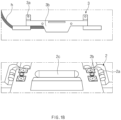
FIG. 1b , which illustrates a shape (below) of a side surface of anupper mask 3 according to the related art and a state (below) in which thebase plate 2 is disposed upside down, andFIG. 1c , which illustrates a cross-sectional view of a state in which theupper mask 3 according to the related art is coupled to thebase plate 2, a locking part 3a protrudes from theupper mask 3 according to the related art, and acatcher 2a, in which the locking part 3a is inserted and fixed, is provided on thebase plate 2. That is, in the structure according to the related art, thebase plate 2 and theupper mask 3 are attached to and detached from each other through coupling and separation of the locking part 3a and thecatcher 2a. Here, the coupling and separation of the locking part 3a and thecatcher 2a are performed manually by a worker using a dedicated tool. - In addition, the
upper mask 3 may be provided with a hollow cone-shaped portion that is pointed toward an electrode tab T and an electrode lead T, and openingholes upper mask 3 may also have a shape that is pointed toward theend 3f of theopening holes upper mask 3 is formed withgas passages 3b and 3c therein so that an inert gas is injected to both sides and supplied to theend 3f of theopening holes gas passages 3b and 3c receives the inert gas through thebase plate 2 and the openedhole 2b (right side inFIG. 1c ), and the other one 3b is directly connected to an external tube or hose H to receive the inert gas (left side inFIG. 1c ). Then, the inert gas collected toward theend 3f of the opening hole is contact with a welded point W and then is discharged through theopening hole 3e of theupper mask 3 and theopening hole 2c of thebase plate 2. - During the welding, melting occurs at the welded point, and spatter S is scattered in the form of small particles. Since the spatter S is attached to a surface of the
upper mask 2, as the welding progresses, there is a problem that the spatter is accumulated on the surface of theupper mask 3 to cover thegas passages 3b and 3c, and as a result, it needs to be replaced periodically. - However, in the structure according to the related art, the external tube or hose H for injecting the inert gas may be separately separated, and then, the locking part 3a and the
catcher 3b are separated from each other to perform detachment of theupper mask 3, but there is a difference in replacement time according to the skill level of the worker, and there is a problem that a welding process is delayed during the replacement time. Although a magnet is attached to the locking part 3a to easily perform the coupling of the locking part 3a and thecatcher 3b by magnetic force, the magnetic force may rather be an obstacle during the separation operation. - Therefore, in the present invention, there is a need to provide a new coupling structure in which the
upper mask 3 and thebase plate 2 are easily coupled to and separated from each other. - Therefore, a main object of the present invention is to provide a laser welding device capable of easily coupling and separating an upper mask to/from a base plate.
- The present invention for achieving the above object provides a laser welding device, which performs welding of an electrode lead and an electrode tab by irradiating laser so that the laser sequentially passes through an opening hole of a base plate and an opening hole of an upper mask when the electrode lead and the electrode tab are seated on a lower mask in a state in which a laser irradiator, the base plate, and the upper mask are coupled to each other, the laser welding device including: the base plate provided with a coupling tool that protrudes from one surface thereof; and the upper mask provided with a coupling hole through which the coupling tool enters and coupled to the base plate by coupling the coupling tool to the coupling hole, wherein the coupling tool comprises a cylinder which has a hollow shape therein in a longitudinal direction and in which an air hole is punched, a piston which is capable of being slid inside the cylinder in a state of being coupled to a spring and has a section of which a diameter is reduced toward one side thereof, and a ball coupled to the cylinder, and wherein, when the coupling tool enters the inside of the coupling hole, the ball enters a groove formed in an inner circumferential surface of the coupling hole by the piston so as to be prevented from being separated, and when air is injected into the air hole, the piston is slid to separate the ball from the groove.
- A flange of which a diameter is expanded may be formed on an end of a side of the piston, at which a diameter is relatively expanded, and the spring may be disposed at one side of the piston, and the air hole may be formed in the cylinder at the other side of the piston with respect to the flange.
- A sleeve may be coupled to the upper mask, and the coupling hole and the groove may be formed in the sleeve so that the coupling tool is coupled to the sleeve. That is, the coupling hole and the groove may be provided in the upper mask itself, or the sleeve may be separately mounted.
- At least two coupling tools may be provided on the base plate, and a plurality of coupling holes corresponding to a number of the coupling tools may be formed in the upper mask.
- A plurality of balls may be coupled along a circumference of the cylinder.
- The upper mask may include a gas passage through which an inert gas moves, and an injection hole through which the inert gas is injected into the gas passage may be formed in the base plate, and when the upper mask is coupled to the base plate, the gas passage and the injection hole may communicate with each other.
- The upper mask may include a hollow cone shaped portion that is pointed to be gathered at an end thereof so that the opening hole through which the laser passes communicates at the end that is pointed to be gathered, and the gas passage may be formed to be continued to the opening hole.
- The gas passage may be formed to be continued from the inside of a shape surface that forms a shape of the upper mask.
- The inert gas injected through the gas passage may be discharged through the opening hole of the base plate and the opening hole of the upper mask.
- The inert gas may include nitrogen (N2).
- In the present invention having the configuration as described above, the detachment of the base plate and the upper mask may be performed by the coupling tool, and since the coupling tool is coupled or separated according to whether the air is injected, the coupling tool may be quickly detachable. Thus, even the unskilled person may more quickly and easily attach and detach the upper mask.
- The coupling hole into which the coupling tool enters and the groove into which the ball of the coupling tool enters may be integrally formed on the upper mask. Alternatively, since the separate sleeve may be provided, the sleeve may be added so that the upper mask according to the related art is used as it is.
- Since the upper mask has the structure in which the inert gas is supplied through the injection hole of the base plate, there may be unnecessary to couple and separate the separate hose for injecting the inert gas or the external tube, thereby more quickly replace the upper mask.
-
-
FIG. 1a is a schematic perspective view illustrating an overall shape of a laser welding device. -
FIG. 1b is a side view illustrating a shape (above) in which an upper mask according to the related art is separated from the laser welding device ofFIG. 1a and a state (below) in which a base plate according to the related art is disposed upside down so that a bottom surface that is in contact with the upper mask is seen. -
FIG. 1c is a cross-sectional view illustrating a state in which the upper mask and the base plate according to the related art are coupled to each other. -
FIG. 2 is a view illustrating a shape (above) in which an upper mask according to the present invention is separated and a state (below) in which a base plate according to the present invention is disposed upside down so that a bottom surface that is in contact with the upper mask is shown. -
FIG. 3 is a cross-sectional view illustrating a portion having a hollow cone shape when the upper mask and the base plate according to the present invention are coupled to each other. -
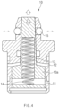
FIG. 4 is a longitudinal cross-sectional view illustrating a coupling tool according to the present invention. -
FIG. 5 is a view illustrating a state (i) in which the coupling tool is locked to a sleeve and a state (ii) in which the coupling tool is unlocked from the sleeve. - Hereinafter, preferred embodiments of the present invention will be described in detail with reference to the accompanying drawings in such a manner that the technical idea of the present invention may easily be carried out by a person with ordinary skill in the art to which the invention pertains. The present invention may, however, be embodied in different forms and should not be construed as limited to the embodiments set forth herein.
- In order to clearly describe the present invention, parts irrelevant to the description are omitted, and the same reference numerals are assigned to the same or similar components throughout the specification.
- Also, terms or words used in this specification and claims should not be restrictively interpreted as ordinary meanings or dictionary-based meanings, but should be interpreted as meanings and concepts conforming to the scope of the present invention on the basis of the principle that an inventor can properly define the concept of a term to describe and explain his or her invention in the best ways.
- The present invention relates to a laser welding device in which welding of an electrode tab and an electrode lead is performed by irradiating laser from a laser irradiator so that the laser sequentially passes through an opening hole of a base plate and an opening hole of an upper mask when the electrode lead and the electrode tab are seated on a lower mask in a state in which the laser irradiator, the base plate, and the upper mask are coupled to each other from top to bottom as illustrated in
FIG. 1 , and hereinafter, an embodiment of the present invention will be described in more detail with reference to the accompanying drawings. - That is, like the above-described structure according to the related art, a laser welding device according to the present invention includes a lower mask, a laser irradiator, a
base plate 20, and anupper mask 30. -
FIG. 2 is a view illustrating a shape (above) in which theupper mask 30 according to the present invention is separated and a state (below) in which thebase plate 20 according to the present invention is disposed upside down so that a bottom surface that is in contact with theupper mask 30 is shown. - Instead of the locking part and the catcher according to the related art, in the structure according to the present invention, the
upper mask 30 is provided with a coupling hole (the coupling hole is integrally formed in the upper mask itself, or a sleeve in which the coupling hole is formed is coupled), and acoupling tool 10 capable of being fixed to the coupling hole is provided on thebase plate 20. - That is, the
base plate 20 has a structure, in which thecoupling tool 10 is mounted on one surface (i.e., a bottom surface when disposed as illustrated inFIG. 1a ), to which theupper mask 30 is coupled, to protrude from the surface, and the coupling hole is provided in theupper mask 30. -
FIG. 3 is a cross-sectional view illustrating a portion having a hollow cone shape when theupper mask 30 and thebase plate 20 according to the present invention are coupled to each other. For reference, a portion at which thecoupling tool 10 is coupled to the coupling hole is omitted inFIG. 3 as a point disposed outside inFIG. 3 . - As illustrated in the drawings, the
upper mask 30 is provided with a portion that is formed in the form of a hollow cone shape that is pointed to be gathered at an end thereof, and thus, openingholes gas passage 31 is also connected to alower end 32c of the opening holes 32a, 32b, and 32c. - The
gas passage 31 is a passage, through which an inert gas moves, and is formed to be continued from the inside of the shape surface forming the shape of theupper mask 30 so that the inert gas is supplied to the point W at which the welding is performed. The shape surface means a portion constituting an outer appearance and having a thickness to form the cone shape in theupper mask 30. - In the
upper mask 30 provided in the present invention, unlike the structure according to the related art, the inert gas may not be directly injected through an external tube or hose H, but may be injected through aninjection hole 21 formed in thebase plate 20. - That is, the external tube or hose H according to the related art is connected to one side of the
injection hole 21 formed in thebase plate 20, and when theupper mask 30 is coupled to the base plate, the other side of theinjection hole 21 communicates with thegas passage 31 of theupper mask 30. - And, as illustrated in
FIG. 3 , while the electrode tab T and the electrode lead L are laser-welded to each other, the inert gas injected through thegas passage 31 acts to stabilize the welding at the point W at which the welding is performed and is continuously supplied and then discharged through theopening hole 22 of thebase plate 20 and the opening holes 32a, 32b, and 32c of theupper mask 30. - That is, the inert gas injected into the
gas passage 31 is discharged through theopening hole 22 of the base plate via alower end 32c, anintermediate end 32b, and anupper end 32a of the opening hole of theupper mask 30. Here, nitrogen (N2) may be provided as the inert gas. - In addition, the
coupling tool 10 provided in the present invention are disposed outside each of the injection holes 21 at both sides of thebase plate 20, as illustrated inFIG. 2 . -
FIG. 4 is a longitudinal cross-sectional view illustrating thecoupling tool 10 according to the present invention, andFIG. 5 is a view illustrating a state (i) in which thecoupling tool 10 is locked to asleeve 40 and a state (ii) in which thecoupling tool 10 is unlocked from thesleeve 40. - The
coupling tool 10 may be configured so that apiston 13 is coupled inside acylinder 11, and aball 15 protrudes from a surface of thecylinder 11 so as to be locked or unlocked according to a sliding position of thepiston 13. - Referring to the drawings, the
cylinder 11 has a hollow shape in a longitudinal direction, and anair hole 12 is punched at a predetermined height. Theair hole 12 allows the inside and outside of thecylinder 11 to communicate with each other. - The
piston 13 is slidably mounted inside thecylinder 11 in a state in which one end of thepiston 13 is pressed by elastic force. Thepiston 13 has a shape of which a diameter decreases toward one side, or a section of which a diameter decreases toward one side thereof is formed on at least a portion of thepiston 13. - In addition, at least one or
more balls 15 are coupled along a circumference of thecylinder 11, preferably a plurality ofballs 15 are coupled at regular intervals along the circumference of thecylinder 11. Although not clearly shown in the drawing, theball 15 is disposed to be coupled and restricted by an elastic body (not shown) so that a portion of theball 15 is embedded into thecylinder 11, and theball 15 is behaved to protrude from the surface of thecylinder 11 when the ball is in contact with a portion at which the diameter of thepiston 13 is expanded according to the sliding of thepiston 13, and to be embedded in an original state when theball 15 is in contact with a portion at which the diameter of thepiston 13 is contracted. - Here, a
flange 13a of which a diameter is expanded is disposed on an end (or the intermediate end) of a side of the piston13, at which a diameter is relatively expanded. In addition, aspring 14 is disposed at one side (a lower side inFIG. 4 ) of thepiston 13, and anair hole 12 is formed in thecylinder 11 at the other side (an upper side inFIG. 4 ) of thepiston 13. - The
piston 13 has a diameter that gradually increases downward inFIG. 4 . Thus, when thepiston 13 ascends by the elastic force of thespring 14, theball 15 is pressed by thepiston 13 to protrude outward from the surface of thecylinder 11. - In addition, when compressed air is supplied to the
air hole 12, a pressure in a space (in detail, a space opposite to a space in which the spring is disposed when the space inside the cylinder is divided with respect to the flange) inside thecylinder 11 increases. Thus, thepiston 13 overcomes the elastic force of thespring 14 to descend, and theball 15 is restored to be embedded in the original state in thecylinder 11 as the pressure pressed by thepiston 13 is released. - In addition, the coupling hole is provided in the
upper mask 30 so that thecoupling tools 10 enter according to positions at which thecoupling tools 10 are disposed, and a groove having a concave shape is formed in an inner circumferential surface of the coupling hole. The coupling hole and the groove may be integrally formed in theupper mask 30, but thesleeve 40 provided with thecoupling hole 41 and thegroove 42 may be provided in a shape coupled to theupper mask 30. -
FIG. 5 is a view illustrating a state in which thecoupling hole 41 and thegroove 42 are provided in aringshaped sleeve 40 that is separately coupled to theupper mask 30, and thecoupling tool 10 is coupled to thesleeve 40. - Referring to
FIG. 5 , as illustrated at a left side, when thecoupling tool 10 enters thecoupling hole 41, theball 15 enters thegroove 42 formed in an inner circumferential surface of thecoupling hole 41 by thepiston 13 so that thecoupling tool 10 is restricted to thesleeve 40. Here, since thecoupling tool 10 is coupled to thebase plate 20 and thesleeve 40 is fixed to theupper mask 30, thebase plate 20 and theupper mast 30 are coupled to each other. That is, thecoupling tool 10 fixed to thebase plate 20 may be fitted into thecoupling hole 41, and thus, thebase plate 20 and theupper mask 30 may be coupled to each other in a one-touch manner. - For reference, the
piston 13 ofFIG. 5 is illustrated as a structure having both the portion of thepiston 13 having the constant diameter and the portion of thepiston 13 having the variable diameter, but the shape of thepiston 13 may vary according to a size of theball 15 or an inner diameter of thecoupling hole 41. - In addition, when the air (compressed air) is injected through the
air hole 12, as illustrated at the right side ofFIG. 5 , the pressure in the space opposite to thespring 14 increases, and thus, thepiston 13 is slid in a direction in which thepiston 13 is retreated (downward inFIG. 5 ). Here, since a point at which the diameter of thepiston 13 is reduced faces theball 15, the pressure applied to theball 15 is released. - Therefore, the
coupling tool 10 may be separated from thecoupling hole 41, and thus, thebase plate 20 and theupper mask 30 may be separated from each other. - In order to properly support a weight of the
upper mask 30, it is preferable that thebase plate 20 is provided with at least two ormore coupling tools 10, and theupper mask 30 has a plurality of coupling holes, which correspond to the number ofcoupling tools 10. In addition, it is preferable to have a structure in which the plurality ofballs 15 are disposed along the circumference of thecylinder 11 so that thecoupling tool 10 is restricted more efficiently. - In the present invention having the configuration as described above, the detachment of the
base plate 20 and theupper mask 30 may be performed by thecoupling tool 10, and since thecoupling tool 10 is coupled or separated according to whether the air is injected, thecoupling tool 10 may be quickly detachable. Thus, even the unskilled person may more quickly and easily attach and detach the upper mask. - The coupling hole into which the
coupling tool 10 enters and the groove into which the ball of the coupling tool enters may be integrally formed on the upper mask. Alternatively, since theseparate sleeve 40 may be provided, thesleeve 40 may be added so that the upper mask according to the related art is used as it is. - Since the
upper mask 30 has the structure in which the inert gas is supplied through the injection hole of thebase plate 20, there may be unnecessary to couple and separate the separate hose H for injecting the inert gas or the external tube, thereby more quickly replace the upper mask. - While the embodiments of the present invention have been described with reference to the specific embodiments, it will be apparent to those skilled in the art that various changes and modifications may be made without departing from the spirit and scope of the invention as defined in the following claims.
-
- 10:
- Coupling tool
- 20:
- Base plate
- 30:
- Upper mask
- 40:
- Sleeve
Claims (10)
- A laser welding device, which performs welding of an electrode lead and an electrode tab by irradiating laser so that the laser sequentially passes through an opening hole of a base plate and an opening hole of an upper mask when the electrode lead and the electrode tab are seated on a lower mask in a state in which a laser irradiator, the base plate, and the upper mask are coupled to each other, the laser welding device comprising:the base plate provided with a coupling tool that protrudes from one surface thereof; andthe upper mask provided with a coupling hole through which the coupling tool enters and coupled to the base plate by coupling the coupling tool to the coupling hole,wherein the coupling tool comprises a cylinder which has a hollow shape therein in a longitudinal direction and in which an air hole is punched, a piston which is capable of being slid inside the cylinder in a state of being coupled to a spring and has a section of which a diameter is reduced toward one side thereof, and a ball coupled to the cylinder, andwherein, when the coupling tool enters the inside of the coupling hole, the ball enters a groove formed in an inner circumferential surface of the coupling hole by the piston so as to be prevented from being separated, and when air is injected into the air hole, the piston is slid to separate the ball from the groove.
- The laser welding device of claim 1, wherein a flange of which a diameter is expanded is formed on an end of a side of the piston, at which a diameter is relatively expanded, and
the spring is disposed at one side of the piston, and the air hole is formed in the cylinder at the other side of the piston with respect to the flange. - The laser welding device of claim 2, wherein a sleeve is coupled to the upper mask, and the coupling hole and the groove are formed in the sleeve so that the coupling tool is coupled to the sleeve.
- The laser welding device of claim 1, wherein at least two coupling tools are provided on the base plate, and a plurality of coupling holes corresponding to a number of the coupling tools are formed in the upper mask.
- The laser welding device of claim 1, wherein a plurality of balls are coupled along a circumference of the cylinder.
- The laser welding device of claim 1, wherein the upper mask comprises a gas passage through which an inert gas moves, and an injection hole through which the inert gas is injected into the gas passage is formed in the base plate, and
when the upper mask is coupled to the base plate, the gas passage and the injection hole communicate with each other. - The laser welding device of claim 6, wherein the upper mask comprises a hollow cone shaped portion that is pointed to be gathered at an end thereof so that the opening hole through which the laser passes communicates at the end that is pointed to be gathered, and
the gas passage is formed to be continued to the opening hole. - The laser welding device of claim 7, wherein the gas passage is formed to be continued from the inside of a shape surface that forms a shape of the upper mask.
- The laser welding device of claim 8, wherein the inert gas injected through the gas passage is discharged through the opening hole of the base plate and the opening hole of the upper mask.
- The laser welding device of claim 6, wherein the inert gas comprises nitrogen.
Applications Claiming Priority (2)
| Application Number | Priority Date | Filing Date | Title |
|---|---|---|---|
| KR1020210140231A KR102803276B1 (en) | 2021-10-20 | 2021-10-20 | Apparatus for laser welding |
| PCT/KR2022/016043 WO2023068843A1 (en) | 2021-10-20 | 2022-10-20 | Laser welding device |
Publications (2)
| Publication Number | Publication Date |
|---|---|
| EP4397430A1 true EP4397430A1 (en) | 2024-07-10 |
| EP4397430A4 EP4397430A4 (en) | 2025-04-16 |
Family
ID=86059526
Family Applications (1)
| Application Number | Title | Priority Date | Filing Date |
|---|---|---|---|
| EP22884065.8A Pending EP4397430A4 (en) | 2021-10-20 | 2022-10-20 | LASER WELDING DEVICE |
Country Status (6)
| Country | Link |
|---|---|
| US (1) | US20250205817A1 (en) |
| EP (1) | EP4397430A4 (en) |
| JP (1) | JP7654929B2 (en) |
| KR (1) | KR102803276B1 (en) |
| CN (1) | CN118043163A (en) |
| WO (1) | WO2023068843A1 (en) |
Family Cites Families (14)
| Publication number | Priority date | Publication date | Assignee | Title |
|---|---|---|---|---|
| GB971537A (en) * | 1959-12-11 | 1964-09-30 | Aerpat Ag | Improvements in or relating to quick release fasteners |
| JPH106062A (en) * | 1996-06-24 | 1998-01-13 | Amada Co Ltd | Yag laser beam machining head, laser beam machining nozzle used for the head, and nozzle magazine for the laser beam machining nozzle |
| JP3416577B2 (en) * | 1999-06-25 | 2003-06-16 | 住友重機械工業株式会社 | Mask attachment / detachment mechanism and method |
| CN103717917B (en) * | 2011-04-20 | 2015-11-25 | 布赖恩投资有限公司 | Not nut bolt |
| US9464655B2 (en) * | 2012-10-26 | 2016-10-11 | United Technologies Corporation | Push-lock pin |
| KR20140065776A (en) * | 2012-11-21 | 2014-05-30 | 주식회사 성우하이텍 | Protective glass unit for laser optic head |
| KR20150079301A (en) * | 2013-12-31 | 2015-07-08 | 주식회사 성우하이텍 | Protective glass unit for laser optic head |
| JP2019013961A (en) * | 2017-07-07 | 2019-01-31 | 株式会社アマダホールディングス | Nozzle fitting method and laser beam machining device |
| WO2019014293A2 (en) * | 2017-07-12 | 2019-01-17 | Oakland University | Rapidly decoupling mechanical connector |
| KR102266473B1 (en) * | 2018-02-12 | 2021-06-16 | 주식회사 엘지에너지솔루션 | Spot welding Jig for electrode lead |
| KR102774812B1 (en) * | 2019-01-08 | 2025-02-27 | 주식회사 엘지에너지솔루션 | Electrode lead tack welding jig of battery cell |
| US11344979B2 (en) * | 2019-01-30 | 2022-05-31 | General Electric Company | Build plate clamping-assembly and additive manufacturing systems and methods of additively printing on workpieces |
| KR102833705B1 (en) * | 2019-10-23 | 2025-07-14 | 주식회사 엘지에너지솔루션 | Laser Welding Adhesion JIG for Secondary Battery Tab and Method of the Same |
| CN211680581U (en) * | 2020-08-13 | 2020-10-16 | 济南金威刻科技发展有限公司 | A device for quick manual nozzle replacement for a laser cutting machine |
-
2021
- 2021-10-20 KR KR1020210140231A patent/KR102803276B1/en active Active
-
2022
- 2022-10-20 CN CN202280065749.7A patent/CN118043163A/en active Pending
- 2022-10-20 WO PCT/KR2022/016043 patent/WO2023068843A1/en not_active Ceased
- 2022-10-20 US US18/702,061 patent/US20250205817A1/en active Pending
- 2022-10-20 EP EP22884065.8A patent/EP4397430A4/en active Pending
- 2022-10-20 JP JP2024521796A patent/JP7654929B2/en active Active
Also Published As
| Publication number | Publication date |
|---|---|
| KR102803276B1 (en) | 2025-05-07 |
| CN118043163A (en) | 2024-05-14 |
| EP4397430A4 (en) | 2025-04-16 |
| WO2023068843A1 (en) | 2023-04-27 |
| KR20230056329A (en) | 2023-04-27 |
| JP7654929B2 (en) | 2025-04-02 |
| US20250205817A1 (en) | 2025-06-26 |
| JP2024538049A (en) | 2024-10-18 |
Similar Documents
| Publication | Publication Date | Title |
|---|---|---|
| EP2876724B1 (en) | Method of manufacturing secondary battery | |
| JP5190491B2 (en) | Secondary battery | |
| US11404752B2 (en) | Cylindrical secondary battery including welding pole | |
| US20110086258A1 (en) | Method for manufacturing secondary battery and secondary battery | |
| EP4293769A1 (en) | Battery cell, battery, and electric device | |
| US8603670B2 (en) | Secondary battery | |
| US20090104525A1 (en) | Secondary battery and manufacturing method thereof | |
| CN120999239A (en) | Battery cells, batteries and electrical devices | |
| EP3696899A1 (en) | Electrode assembly and secondary battery comprising same | |
| EP4672449A2 (en) | BATTERY CELL, METHOD AND SYSTEM FOR MANUFACTURING THEM, BATTERY AND ELECTRICAL DEVICE | |
| US12230814B2 (en) | Rectangular secondary battery and assembled battery including the same | |
| US20130052500A1 (en) | Prismatic secondary battery | |
| KR20100081342A (en) | Battery and method for manufacturing same | |
| US20250205817A1 (en) | Laser Welding Device | |
| EP4447219A1 (en) | Battery end cover assembly, battery cell, battery and electrical device | |
| KR20230100654A (en) | Method of manufacturing battery | |
| KR20140032712A (en) | Secondary battery | |
| EP4559616A1 (en) | Device for collecting foreign substances generated during laser notching, and method for collecting foreign substances by using same | |
| KR102960066B1 (en) | Apparatus for injecting electrolyte for secondary battery having electrolyte scattering prevention structure | |
| US20240405387A1 (en) | Electrical energy storage device and manufacturing method for the same | |
| US20250293384A1 (en) | Cell integrated vent gas diverter with particle trap | |
| US20250337135A1 (en) | Bonding method, and electrical energy storage device and manufacturing method for the same | |
| JP7638240B2 (en) | battery | |
| KR102227805B1 (en) | Rechargeable battery and the manufacturing method | |
| EP4239762A1 (en) | Pouch-type secondadry battery, sealing device for secondary battery, and sealing method for secondary battery |
Legal Events
| Date | Code | Title | Description |
|---|---|---|---|
| STAA | Information on the status of an ep patent application or granted ep patent |
Free format text: STATUS: THE INTERNATIONAL PUBLICATION HAS BEEN MADE |
|
| PUAI | Public reference made under article 153(3) epc to a published international application that has entered the european phase |
Free format text: ORIGINAL CODE: 0009012 |
|
| STAA | Information on the status of an ep patent application or granted ep patent |
Free format text: STATUS: REQUEST FOR EXAMINATION WAS MADE |
|
| 17P | Request for examination filed |
Effective date: 20240405 |
|
| AK | Designated contracting states |
Kind code of ref document: A1 Designated state(s): AL AT BE BG CH CY CZ DE DK EE ES FI FR GB GR HR HU IE IS IT LI LT LU LV MC ME MK MT NL NO PL PT RO RS SE SI SK SM TR |
|
| DAV | Request for validation of the european patent (deleted) | ||
| DAX | Request for extension of the european patent (deleted) | ||
| A4 | Supplementary search report drawn up and despatched |
Effective date: 20250313 |
|
| RIC1 | Information provided on ipc code assigned before grant |
Ipc: B23K 101/38 20060101ALN20250307BHEP Ipc: B23K 26/22 20060101ALI20250307BHEP Ipc: F16B 21/16 20060101ALI20250307BHEP Ipc: B23K 26/14 20140101ALI20250307BHEP Ipc: B23K 37/04 20060101ALI20250307BHEP Ipc: B23K 26/21 20140101AFI20250307BHEP |
|
| STAA | Information on the status of an ep patent application or granted ep patent |
Free format text: STATUS: EXAMINATION IS IN PROGRESS |
|
| 17Q | First examination report despatched |
Effective date: 20251013 |
|
| GRAP | Despatch of communication of intention to grant a patent |
Free format text: ORIGINAL CODE: EPIDOSNIGR1 |
|
| STAA | Information on the status of an ep patent application or granted ep patent |
Free format text: STATUS: GRANT OF PATENT IS INTENDED |
|
| RIC1 | Information provided on ipc code assigned before grant |
Ipc: B23K 26/21 20140101AFI20260102BHEP Ipc: B23K 37/04 20060101ALI20260102BHEP Ipc: B23K 26/14 20140101ALI20260102BHEP Ipc: F16B 21/16 20060101ALI20260102BHEP Ipc: B23K 26/22 20060101ALI20260102BHEP Ipc: B23K 101/38 20060101ALN20260102BHEP |
|
| RIC1 | Information provided on ipc code assigned before grant |
Ipc: B23K 26/21 20140101AFI20260121BHEP Ipc: B23K 37/04 20060101ALI20260121BHEP Ipc: B23K 26/14 20140101ALI20260121BHEP Ipc: F16B 21/16 20060101ALI20260121BHEP Ipc: B23K 26/22 20060101ALI20260121BHEP Ipc: B23K 101/38 20060101ALN20260121BHEP |
|
| INTG | Intention to grant announced |
Effective date: 20260205 |
|
| P01 | Opt-out of the competence of the unified patent court (upc) registered |
Free format text: CASE NUMBER: UPC_APP_0009398_4397430/2026 Effective date: 20260311 |
|
| GRAS | Grant fee paid |
Free format text: ORIGINAL CODE: EPIDOSNIGR3 |
|
| GRAA | (expected) grant |
Free format text: ORIGINAL CODE: 0009210 |
|
| STAA | Information on the status of an ep patent application or granted ep patent |
Free format text: STATUS: THE PATENT HAS BEEN GRANTED |