EP4397400A1 - Ultrafine bubble-containing liquid producing apparatus and method - Google Patents
Ultrafine bubble-containing liquid producing apparatus and method Download PDFInfo
- Publication number
- EP4397400A1 EP4397400A1 EP23219845.7A EP23219845A EP4397400A1 EP 4397400 A1 EP4397400 A1 EP 4397400A1 EP 23219845 A EP23219845 A EP 23219845A EP 4397400 A1 EP4397400 A1 EP 4397400A1
- Authority
- EP
- European Patent Office
- Prior art keywords
- liquid
- ultrafine bubble
- unit
- producing apparatus
- temperature
- Prior art date
- Legal status (The legal status is an assumption and is not a legal conclusion. Google has not performed a legal analysis and makes no representation as to the accuracy of the status listed.)
- Pending
Links
Images






Classifications
-
- B—PERFORMING OPERATIONS; TRANSPORTING
- B01—PHYSICAL OR CHEMICAL PROCESSES OR APPARATUS IN GENERAL
- B01F—MIXING, e.g. DISSOLVING, EMULSIFYING OR DISPERSING
- B01F23/00—Mixing according to the phases to be mixed, e.g. dispersing or emulsifying
- B01F23/20—Mixing gases with liquids
- B01F23/29—Mixing systems, i.e. flow charts or diagrams
- B01F23/291—Mixing systems, i.e. flow charts or diagrams for obtaining foams or aerosols
-
- B—PERFORMING OPERATIONS; TRANSPORTING
- B01—PHYSICAL OR CHEMICAL PROCESSES OR APPARATUS IN GENERAL
- B01F—MIXING, e.g. DISSOLVING, EMULSIFYING OR DISPERSING
- B01F23/00—Mixing according to the phases to be mixed, e.g. dispersing or emulsifying
- B01F23/20—Mixing gases with liquids
- B01F23/23—Mixing gases with liquids by introducing gases into liquid media, e.g. for producing aerated liquids
- B01F23/2319—Methods of introducing gases into liquid media
-
- B—PERFORMING OPERATIONS; TRANSPORTING
- B01—PHYSICAL OR CHEMICAL PROCESSES OR APPARATUS IN GENERAL
- B01F—MIXING, e.g. DISSOLVING, EMULSIFYING OR DISPERSING
- B01F23/00—Mixing according to the phases to be mixed, e.g. dispersing or emulsifying
- B01F23/20—Mixing gases with liquids
- B01F23/23—Mixing gases with liquids by introducing gases into liquid media, e.g. for producing aerated liquids
- B01F23/232—Mixing gases with liquids by introducing gases into liquid media, e.g. for producing aerated liquids using flow-mixing means for introducing the gases, e.g. baffles
- B01F23/2323—Mixing gases with liquids by introducing gases into liquid media, e.g. for producing aerated liquids using flow-mixing means for introducing the gases, e.g. baffles by circulating the flow in guiding constructions or conduits
-
- B—PERFORMING OPERATIONS; TRANSPORTING
- B01—PHYSICAL OR CHEMICAL PROCESSES OR APPARATUS IN GENERAL
- B01F—MIXING, e.g. DISSOLVING, EMULSIFYING OR DISPERSING
- B01F23/00—Mixing according to the phases to be mixed, e.g. dispersing or emulsifying
- B01F23/20—Mixing gases with liquids
- B01F23/23—Mixing gases with liquids by introducing gases into liquid media, e.g. for producing aerated liquids
- B01F23/235—Mixing gases with liquids by introducing gases into liquid media, e.g. for producing aerated liquids for making foam
-
- B—PERFORMING OPERATIONS; TRANSPORTING
- B01—PHYSICAL OR CHEMICAL PROCESSES OR APPARATUS IN GENERAL
- B01F—MIXING, e.g. DISSOLVING, EMULSIFYING OR DISPERSING
- B01F23/00—Mixing according to the phases to be mixed, e.g. dispersing or emulsifying
- B01F23/20—Mixing gases with liquids
- B01F23/23—Mixing gases with liquids by introducing gases into liquid media, e.g. for producing aerated liquids
- B01F23/237—Mixing gases with liquids by introducing gases into liquid media, e.g. for producing aerated liquids characterised by the physical or chemical properties of gases or vapours introduced in the liquid media
- B01F23/2373—Mixing gases with liquids by introducing gases into liquid media, e.g. for producing aerated liquids characterised by the physical or chemical properties of gases or vapours introduced in the liquid media for obtaining fine bubbles, i.e. bubbles with a size below 100 µm
-
- B—PERFORMING OPERATIONS; TRANSPORTING
- B01—PHYSICAL OR CHEMICAL PROCESSES OR APPARATUS IN GENERAL
- B01F—MIXING, e.g. DISSOLVING, EMULSIFYING OR DISPERSING
- B01F23/00—Mixing according to the phases to be mixed, e.g. dispersing or emulsifying
- B01F23/20—Mixing gases with liquids
- B01F23/23—Mixing gases with liquids by introducing gases into liquid media, e.g. for producing aerated liquids
- B01F23/237—Mixing gases with liquids by introducing gases into liquid media, e.g. for producing aerated liquids characterised by the physical or chemical properties of gases or vapours introduced in the liquid media
- B01F23/2373—Mixing gases with liquids by introducing gases into liquid media, e.g. for producing aerated liquids characterised by the physical or chemical properties of gases or vapours introduced in the liquid media for obtaining fine bubbles, i.e. bubbles with a size below 100 µm
- B01F23/2375—Mixing gases with liquids by introducing gases into liquid media, e.g. for producing aerated liquids characterised by the physical or chemical properties of gases or vapours introduced in the liquid media for obtaining fine bubbles, i.e. bubbles with a size below 100 µm for obtaining bubbles with a size below 1 µm
-
- B—PERFORMING OPERATIONS; TRANSPORTING
- B01—PHYSICAL OR CHEMICAL PROCESSES OR APPARATUS IN GENERAL
- B01F—MIXING, e.g. DISSOLVING, EMULSIFYING OR DISPERSING
- B01F23/00—Mixing according to the phases to be mixed, e.g. dispersing or emulsifying
- B01F23/80—After-treatment of the mixture
- B01F23/802—Cooling the mixture
-
- B—PERFORMING OPERATIONS; TRANSPORTING
- B01—PHYSICAL OR CHEMICAL PROCESSES OR APPARATUS IN GENERAL
- B01F—MIXING, e.g. DISSOLVING, EMULSIFYING OR DISPERSING
- B01F25/00—Flow mixers; Mixers for falling materials, e.g. solid particles
- B01F25/50—Circulation mixers, e.g. wherein at least part of the mixture is discharged from and reintroduced into a receptacle
- B01F25/51—Circulation mixers, e.g. wherein at least part of the mixture is discharged from and reintroduced into a receptacle in which the mixture is circulated through a set of tubes, e.g. with gradual introduction of a component into the circulating flow
-
- B—PERFORMING OPERATIONS; TRANSPORTING
- B01—PHYSICAL OR CHEMICAL PROCESSES OR APPARATUS IN GENERAL
- B01F—MIXING, e.g. DISSOLVING, EMULSIFYING OR DISPERSING
- B01F33/00—Other mixers; Mixing plants; Combinations of mixers
- B01F33/30—Micromixers
- B01F33/3033—Micromixers using heat to mix or move the fluids
-
- B—PERFORMING OPERATIONS; TRANSPORTING
- B01—PHYSICAL OR CHEMICAL PROCESSES OR APPARATUS IN GENERAL
- B01F—MIXING, e.g. DISSOLVING, EMULSIFYING OR DISPERSING
- B01F35/00—Accessories for mixers; Auxiliary operations or auxiliary devices; Parts or details of general application
- B01F35/181—Preventing generation of dust or dirt; Sieves; Filters
- B01F35/189—Venting, degassing or ventilating of gases, fumes or toxic vapours during mixing
-
- B—PERFORMING OPERATIONS; TRANSPORTING
- B01—PHYSICAL OR CHEMICAL PROCESSES OR APPARATUS IN GENERAL
- B01F—MIXING, e.g. DISSOLVING, EMULSIFYING OR DISPERSING
- B01F35/00—Accessories for mixers; Auxiliary operations or auxiliary devices; Parts or details of general application
- B01F35/20—Measuring; Control or regulation
- B01F35/21—Measuring
- B01F35/211—Measuring of the operational parameters
- B01F35/2115—Temperature
-
- B—PERFORMING OPERATIONS; TRANSPORTING
- B01—PHYSICAL OR CHEMICAL PROCESSES OR APPARATUS IN GENERAL
- B01F—MIXING, e.g. DISSOLVING, EMULSIFYING OR DISPERSING
- B01F35/00—Accessories for mixers; Auxiliary operations or auxiliary devices; Parts or details of general application
- B01F35/20—Measuring; Control or regulation
- B01F35/21—Measuring
- B01F35/2132—Concentration, pH, pOH, p(ION) or oxygen-demand
-
- B—PERFORMING OPERATIONS; TRANSPORTING
- B01—PHYSICAL OR CHEMICAL PROCESSES OR APPARATUS IN GENERAL
- B01F—MIXING, e.g. DISSOLVING, EMULSIFYING OR DISPERSING
- B01F35/00—Accessories for mixers; Auxiliary operations or auxiliary devices; Parts or details of general application
- B01F35/20—Measuring; Control or regulation
- B01F35/22—Control or regulation
- B01F35/221—Control or regulation of operational parameters, e.g. level of material in the mixer, temperature or pressure
- B01F35/2211—Amount of delivered fluid during a period
-
- B—PERFORMING OPERATIONS; TRANSPORTING
- B01—PHYSICAL OR CHEMICAL PROCESSES OR APPARATUS IN GENERAL
- B01F—MIXING, e.g. DISSOLVING, EMULSIFYING OR DISPERSING
- B01F35/00—Accessories for mixers; Auxiliary operations or auxiliary devices; Parts or details of general application
- B01F35/20—Measuring; Control or regulation
- B01F35/22—Control or regulation
- B01F35/221—Control or regulation of operational parameters, e.g. level of material in the mixer, temperature or pressure
- B01F35/2215—Temperature
-
- B—PERFORMING OPERATIONS; TRANSPORTING
- B01—PHYSICAL OR CHEMICAL PROCESSES OR APPARATUS IN GENERAL
- B01F—MIXING, e.g. DISSOLVING, EMULSIFYING OR DISPERSING
- B01F35/00—Accessories for mixers; Auxiliary operations or auxiliary devices; Parts or details of general application
- B01F35/20—Measuring; Control or regulation
- B01F35/22—Control or regulation
- B01F35/221—Control or regulation of operational parameters, e.g. level of material in the mixer, temperature or pressure
- B01F35/2216—Time, i.e. duration, of at least one parameter during the operation
-
- B—PERFORMING OPERATIONS; TRANSPORTING
- B01—PHYSICAL OR CHEMICAL PROCESSES OR APPARATUS IN GENERAL
- B01F—MIXING, e.g. DISSOLVING, EMULSIFYING OR DISPERSING
- B01F35/00—Accessories for mixers; Auxiliary operations or auxiliary devices; Parts or details of general application
- B01F35/20—Measuring; Control or regulation
- B01F35/22—Control or regulation
- B01F35/221—Control or regulation of operational parameters, e.g. level of material in the mixer, temperature or pressure
- B01F35/2216—Time, i.e. duration, of at least one parameter during the operation
- B01F35/22161—Time, i.e. duration, of at least one parameter during the operation duration of the mixing process or parts of it
-
- B—PERFORMING OPERATIONS; TRANSPORTING
- B01—PHYSICAL OR CHEMICAL PROCESSES OR APPARATUS IN GENERAL
- B01F—MIXING, e.g. DISSOLVING, EMULSIFYING OR DISPERSING
- B01F35/00—Accessories for mixers; Auxiliary operations or auxiliary devices; Parts or details of general application
- B01F35/90—Heating or cooling systems
- B01F35/93—Heating or cooling systems arranged inside the receptacle
Definitions
- Japanese Patent Laid-Open No. 2015-181976 discloses an apparatus in which a pressurized dissolution unit that pressurizes a desired gas to dissolve it into a liquid, and a fine bubble generation unit that ejects the liquid from a minute nozzle to generate fine bubbles are provided in the same liquid circulation path to generate fine bubbles at high density.
- the present invention in its first aspect provides a manufacturing apparatus for liquid containing ultrafine bubbles as in claims 1 to 16.
- Fig. 1 is a schematic configuration diagram illustrating an ultrafine bubble-containing liquid producing apparatus 2000 (hereinafter referred to as “UFB-containing liquid producing apparatus 2000") to which the present embodiment is applicable.
- the UFB-containing liquid producing apparatus 2000 includes a liquid supplying unit 600, a gas dissolving unit 800, a storing chamber 900, and an ultrafine bubble generating unit 1000 (hereinafter referred to as “UFB generating unit 1000").
- each solid arrow represents a liquid flow
- each dotted arrow represents a gas flow.
- the liquid supplying unit 600 includes a liquid reservoir unit 601, two pumps 602 and 603, and a degassing unit 604.
- a liquid W contained in the liquid reservoir unit 601 is transferred to the storing chamber 900, which is capable of storing the liquid, by the pump 602 via the degassing unit 604.
- Inside the degassing unit 604 is disposed a film through which only gases can pass. With the pump 603 actuated, the inside of the degassing unit 604 is depressurized, and only gases pass through the film, so that the gases and the liquid are separated from each other.
- the liquid W is moved toward the storing chamber 900 whereas the gases are discharged to the outside.
- gases may be dissolved in the liquid contained in the liquid reservoir unit 601. Removing the dissolved gases at the degassing unit 604 before transferring the liquid to the storing chamber 900 enhances the efficiency of dissolution in a subsequent gas dissolving step.
- the gas dissolving unit 800 includes a gas supplying unit 804, a pre-processing unit 801, a merging part 802, and a gas-liquid separating chamber 803. While the gas supplying unit 804 may be a gas cylinder storing a desired gas G, the gas supplying unit 804 may be an apparatus capable of continuously generating the desired gas G. For example, in a case where the desired gas G is oxygen, it is possible to employ an apparatus that takes in the atmospheric air, removes nitrogen, and feeds the gas from which nitrogen has been removed with a pump.
- the gas G supplied by the gas supplying unit 804 is subjected to a process such as electrical discharging at the pre-processing unit 801. Then, at the merging part 802, the gas G merges with the liquid W having flowed out of the storing chamber 900. At this time, part of the gas G gets dissolved into the liquid W. The gas G and the liquid W having thus merged are separated from each other again at the gas-liquid separating chamber 803, and only the part of the gas G that has not been dissolved into the liquid W is discharged to the outside. The liquid W with the gas G dissolved therein is then transferred to the UFB generating unit 1000 by a pump 703.
- the storing chamber 900 stores a mixed liquid of the liquid W supplied from the liquid supplying unit 600, the liquid W in which the desired gas G has been dissolved by the gas dissolving unit 800, and the UFB-containing liquid generated by the UFB generating unit 1000.
- a temperature sensor 905 detects the temperature of the liquid stored in the storing chamber 900.
- a liquid surface sensor 902 is disposed at a predetermined height in the storing chamber 900 and detects the surface of the liquid W.
- a UFB density sensor (density detecting unit) 906 detects the UFB density of the liquid W stored in the storing chamber 900.
- a dissolution degree sensor 907 detects the degree of dissolution of gases in the liquid W stored in the storing chamber 900.
- a valve 904 is opened in a case of discharging the liquid W stored in the storing chamber 900 to a container on the outside through a collection path 909.
- the storing chamber 900 can be provided with an agitating unit therein for making the temperature of and the UFB distribution in the liquid W uniform.
- the driving of the supply pump 703, the collection pump 704, and the UFB generating unit 1000 is controlled based on the value of the temperature sensors. For this reason, a table in which driving frequencies and driving times are associated with each other does not need to be stored in the ROM in advance as described in the first embodiment, and UFBs can be generated freely under a desired condition.
- a third embodiment of the present disclosure will be described below with reference to drawings. Note that the basic configuration in the present embodiment is similar to that in the first embodiment, and the characteristic configuration will therefore be described below.
- a process of removing bubbles generated inside and/or having entered the UFB generating unit 1000 is performed as a process in the UFB generating step.
- the CPU 2001 determines whether the density of UFBs in the UFB-containing liquid inside the storing chamber 900 has reached a predetermined density based on the detection value of the UFB density sensor 906.
- the CPU 2001 returns S901 and repeats the processes if the density has not reached the predetermined density.
- the CPU 2001 terminates the process if the density has reached the predetermined density.
Landscapes
- Chemical & Material Sciences (AREA)
- Chemical Kinetics & Catalysis (AREA)
- Engineering & Computer Science (AREA)
- Nanotechnology (AREA)
- Health & Medical Sciences (AREA)
- General Health & Medical Sciences (AREA)
- Toxicology (AREA)
- Dispersion Chemistry (AREA)
- Accessories For Mixers (AREA)
Abstract
Description
- The present disclosure relates to an ultrafine bubble-containing liquid producing apparatus and method.
- In recent years, techniques have been developed which use characteristics of fine bubbles such as microbubbles measuring 1 to 100 µm in diameter and ultrafine bubbles (hereinafter referred to also as "UFBs") measuring less than 1.0 µm in diameter.
-
Japanese Patent Laid-Open No. 2015-181976 - Also,
Japanese Patent Laid-Open No. 2019-42732 - Here, in a case where a UFB producing apparatus operates for a long period of time, the temperature of its UFB generating unit rises. As a result, the temperature of the liquid rises. This leads to a possibility of lowering the degree of dissolution of the gas and decreasing the amount of the gas dissolved in the liquid, thereby decreasing the UFB generation efficiency.
- In view of the above, the present disclosure provides a UFB-containing liquid producing apparatus and method capable of preventing a decrease in UFB generation efficiency in a long period of operation.
- The present invention in its first aspect provides a manufacturing apparatus for liquid containing ultrafine bubbles as in
claims 1 to 16. - The present invention in its second aspect provides a manufacturing method for liquid containing ultrafine bubbles as in claim 17.
- Further features of the present disclosure will become apparent from the following description of exemplary embodiments with reference to the attached drawings.
-
-
Fig. 1 is a schematic configuration diagram illustrating an ultrafine bubble-containing liquid producing apparatus; -
Fig. 2 is a perspective view illustrating a UFB generating unit; -
Fig. 3 is an exploded perspective view of a heating element substrate; -
Fig. 4 is a block diagram illustrating a control configuration in the UFB-containing liquid producing apparatus; -
Fig. 5 is a flowchart illustrating a process of generating a UFB-containing liquid; -
Fig. 6 is a flowchart illustrating processes in a UFB generating step; -
Fig. 7 is a flowchart illustrating processes in a UFB generating step; -
Fig. 8A is a graph illustrating a temperature rise profile obtained by actually measuring the temperature of the UFB generating unit; -
Fig. 8B is a graph illustrating a temperature rise profile obtained by actually measuring the temperature of the UFB generating unit; -
Fig. 9A is a flowchart illustrating processes in a UFB generating step; -
Fig. 9B is a flowchart illustrating processes in the UFB generating step; and -
Fig. 9C is a flowchart illustrating processes in the UFB generating step. - A first embodiment of the present disclosure will be described below with reference to drawings.
-
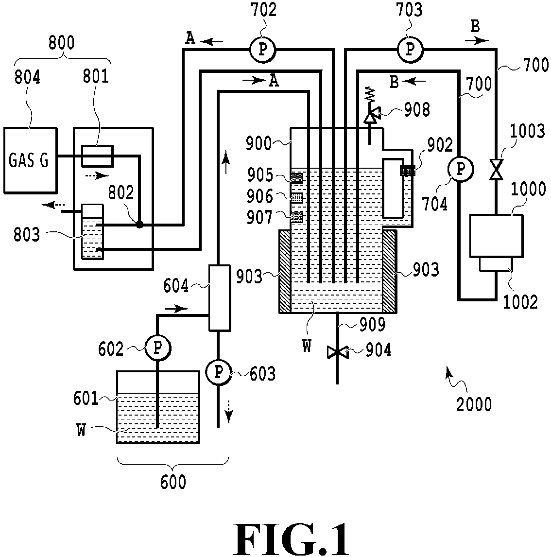
Fig. 1 is a schematic configuration diagram illustrating an ultrafine bubble-containing liquid producing apparatus 2000 (hereinafter referred to as "UFB-containingliquid producing apparatus 2000") to which the present embodiment is applicable. The UFB-containingliquid producing apparatus 2000 includes aliquid supplying unit 600, a gas dissolvingunit 800, astoring chamber 900, and an ultrafine bubble generating unit 1000 (hereinafter referred to as "UFB generating unit 1000"). InFig. 1 , each solid arrow represents a liquid flow, and each dotted arrow represents a gas flow. - The
liquid supplying unit 600 includes aliquid reservoir unit 601, twopumps degassing unit 604. A liquid W contained in theliquid reservoir unit 601 is transferred to thestoring chamber 900, which is capable of storing the liquid, by thepump 602 via thedegassing unit 604. Inside the degassingunit 604 is disposed a film through which only gases can pass. With thepump 603 actuated, the inside of the degassingunit 604 is depressurized, and only gases pass through the film, so that the gases and the liquid are separated from each other. - The liquid W is moved toward the
storing chamber 900 whereas the gases are discharged to the outside. Various gases may be dissolved in the liquid contained in theliquid reservoir unit 601. Removing the dissolved gases at thedegassing unit 604 before transferring the liquid to thestoring chamber 900 enhances the efficiency of dissolution in a subsequent gas dissolving step. - The
gas dissolving unit 800 includes agas supplying unit 804, apre-processing unit 801, a mergingpart 802, and a gas-liquid separating chamber 803. While thegas supplying unit 804 may be a gas cylinder storing a desired gas G, thegas supplying unit 804 may be an apparatus capable of continuously generating the desired gas G. For example, in a case where the desired gas G is oxygen, it is possible to employ an apparatus that takes in the atmospheric air, removes nitrogen, and feeds the gas from which nitrogen has been removed with a pump. - The gas G supplied by the
gas supplying unit 804 is subjected to a process such as electrical discharging at thepre-processing unit 801. Then, at themerging part 802, the gas G merges with the liquid W having flowed out of thestoring chamber 900. At this time, part of the gas G gets dissolved into the liquid W. The gas G and the liquid W having thus merged are separated from each other again at the gas-liquid separating chamber 803, and only the part of the gas G that has not been dissolved into the liquid W is discharged to the outside. The liquid W with the gas G dissolved therein is then transferred to the UFB generatingunit 1000 by apump 703. - The
storing chamber 900 stores a mixed liquid of the liquid W supplied from theliquid supplying unit 600, the liquid W in which the desired gas G has been dissolved by the gas dissolvingunit 800, and the UFB-containing liquid generated by theUFB generating unit 1000. Atemperature sensor 905 detects the temperature of the liquid stored in thestoring chamber 900. Aliquid surface sensor 902 is disposed at a predetermined height in thestoring chamber 900 and detects the surface of the liquid W. A UFB density sensor (density detecting unit) 906 detects the UFB density of the liquid W stored in thestoring chamber 900. Adissolution degree sensor 907 detects the degree of dissolution of gases in the liquid W stored in thestoring chamber 900. Avalve 904 is opened in a case of discharging the liquid W stored in thestoring chamber 900 to a container on the outside through acollection path 909. Though not illustrated inFig. 1 , thestoring chamber 900 can be provided with an agitating unit therein for making the temperature of and the UFB distribution in the liquid W uniform. - A
cooling unit 903 is capable of controlling the temperature of the liquid W stored in thestoring chamber 900, and is capable of cooling the liquid W that has become hot. It is preferable that the temperature of the liquid W to be supplied to the gas dissolvingunit 800 be as low as possible in order to efficiently dissolve the desired gas G at the gas dissolvingunit 800. In the present embodiment, the temperature of the liquid W to be supplied to the gas dissolvingunit 800 is adjusted at 10°C or lower by using thecooling unit 903 while the temperature of the liquid W is detected with thetemperature sensor 905. The configuration of thecooling unit 903 is not particularly limited. For example, it is possible to employ a type which uses a Peltier device or a type which circulates a liquid cooled by a chiller. In the case of the latter, a cooling tube through which a cooling liquid is circulated can be wound around the outer periphery of thestoring chamber 900 as illustrated inFig. 1 , or thestoring chamber 900 can be formed to have a hollow structure with a cooling tube disposed in the hollow space. Alternatively, the configuration can be such that a cooling tube is immersed in the liquid W inside thestoring chamber 900. - A valve 1003 (closing unit) is provided upstream of the
UFB generating unit 1000, and apump 704 is provided downstream of theUFB generating unit 1000. -
Fig. 2 is a perspective view illustrating theUFB generating unit 1000.Fig. 3 is an exploded perspective view of aheating element substrate 1100. TheUFB generating unit 1000 generates UFBs in the liquid W caused to flow into theUFB generating unit 1000. In the present embodiment, a thermal-ultrafine bubble (hereinafter referred to also as "T-UFB") method that causes film boiling at the interfaces betweenheating elements 1102 and the liquid is used as the method of generating UFBs. TheUFB generating unit 1000 includes a plurality of theheating element substrates 1100. Eachheating element substrate 1100 includes aSi substrate 1101 and anejection port plate 1110.Multiple ejection ports 1112 are disposed in theejection port plate 1110, andmultiple heating elements 1102 are disposed on theSi substrate 1101. The multipleheating element substrates 1100 are supported and arrayed on asupport member 1300 attached to a UFBgenerating unit housing 1400.Terminals 1103 for connecting toflexible wirings 1200 are disposed on theSi substrate 1101. Theheating elements 1102 are supplied with electric power through theflexible wirings 1200 and theterminals 1103. Theheating elements 1102 generate heat as voltage pulses applied to them. The liquid is supplied fromsupply paths 1104 to theheating elements 1102, which are caused to generate heat to eject droplets containing UFBs from theejection ports 1112. Temperature sensors (temperature detecting unit) 1107 are formed at regions of theheating element substrate 1100 where theheating elements 1102 are not disposed, and read the temperature of theheating element substrate 1100. - As illustrated in
Fig. 1 , theliquid supplying unit 600, thegas dissolving unit 800, the storingchamber 900, and theUFB generating unit 1000 are connected bypipes 700 and form a path through which the liquid W is circulated with apump 702, thesupply pump 703, and thecollection pump 704.Fig. 1 illustrates a case where a circulation path A for dissolving the gas and a circulation path B for generating a UFB-containing liquid are formed. In this case, the circulation paths A and B are each capable of circulation under any conditions. - In the circulation path B, the liquid W can be circulated with or without the
UFB generating unit 1000 driven. In a case where theUFB generating unit 1000 is not driven, the liquid supplied from thesupply paths 1104, flowing over the surfaces of theheating elements 1102, and passing through theejection ports 1112 is circulated. In a case where theUFB generating unit 1000 is driven, the liquid supplied from thesupply paths 1104 and ejected from theejection ports 1112 by driving theheating elements 1102 is circulated. The flow velocity in the circulation path B may be determined based on the total amount of droplets to be ejected from theejection ports 1112 in theUFB generating unit 1000 or the like. -
Fig. 1 illustrates a configuration provided with the circulation path A including thegas dissolving unit 800 at an intermediate portion of the circulation path for dissolving the gas. Alternatively, a configuration in which the gas G is supplied directly to the storingchamber 900 can be employed. In this way, a smaller UFB-containing liquid producing apparatus can be implemented. - The positions of the pumps and the number of pumps are not limited to those illustrated in
Fig. 1 . Moreover, each component's configuration can be provided with a pump and/or a valve that may be necessary to drive the component. A pump whose pulsation and flow rate variation are small is preferably used to avoid impairing the UFB generation efficiency. Also, thecollection path 909 and thevalve 904 for collecting the liquid W can be provided not at the storingchamber 900 but at another position in either liquid circulation path. Thetemperature sensor 905, theUFB density sensor 906, and thedissolution degree sensor 907 do not necessarily have to be provided at the positions illustrated inFig. 1 . These sensors can be provided at other positions as long as they are within the circulation paths. Alternatively, the configuration can be such that each sensor is provided at a plurality of positions in the circulation paths and an average value can be outputted. - Members that contact the UFB-containing liquid such as the
pipes 700, thepump 702, thesupply pump 703, thecollection pump 704, thevalve 1003, the storingchamber 900, and theUFB generating unit 1000 are preferably made of a material with high corrosion resistance. For example, a fluorine-based resin such as polytetrafluoroethylene (PTFE) or perfluoroalkoxy alkane (PFA), a metal such as SUS316L, or another inorganic material can be preferably used. In this way, it is possible to generate UFBs in a suitable manner even in a case of using a highly corrosive gas G and liquid W. - In the present embodiment, the configuration is such that the liquid W is circulated between the
UFB generating unit 1000 and the storingchamber 900 through the circulation path B. Here, in theUFB generating unit 1000, the circulation includes a step of ejecting droplets from the ejection ports and collecting the droplets with a collectingmember 1002. Thus, the circulation path includes a portion where the liquid W flies through a gap in the form of droplets. -
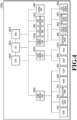
Fig. 4 is a block diagram illustrating a control configuration in the UFB-containingliquid producing apparatus 2000 in the present embodiment. A central processing unit (CPU) 2001 controls the entire apparatus while using a random-access memory (RAM) 2003 as a work area based on a program stored in a rear-only memory (ROM) 2002. Under the instruction of theCPU 2001, apump control unit 2004 controls the driving of various pumps provided in the circulation paths illustrated inFig. 1 , including thepumps valve control unit 2005 is configured to be capable of controlling the opening and closing of various valves including thevalves CPU 2001. Under the instruction of theCPU 2001, asensor control unit 2006 controls various sensors including thedissolution degree sensor 907, theliquid surface sensor 902, thetemperature sensor 905, and theUFB density sensor 906 and provides the detection values of the various sensors to theCPU 2001. -
Fig. 5 is a flowchart illustrating a process of generating a UFB-containing liquid by the UFB-containingliquid producing apparatus 2000 in the present embodiment. TheCPU 2001 of the UFB-containingliquid producing apparatus 2000 performs the series of processes illustrated inFig. 5 by loading program code stored in theROM 2002 to theRAM 2003 and executing it. Alternatively, the functions of some or all of the steps inFig. 5 can be implemented with hardware such as an application-specific integrated circuit (ASIC) or an electronic circuit. The symbol "S" in the description of each process means a step in the flowchart. - Upon start of the process of generating a UFB-containing liquid, the
CPU 2001 stores a predetermined amount of the liquid in the storingchamber 900 in S501. Specifically, theCPU 2001 drives thepumps liquid surface sensor 902. Thus, the liquid W stored in theliquid supplying unit 600 is degassed at thedegassing unit 604 and transferred to the storingchamber 900. Then, in a case where theliquid surface sensor 902 detects the liquid surface, theCPU 2001 stops driving thepumps chamber 900. Then, in S502, theCPU 2001 starts controlling the temperature of the liquid W stored in the storingchamber 900. Specifically, theCPU 2001 drives thecooling unit 903 while monitoring the temperature detected by thetemperature sensor 905. Then, in S503, theCPU 2001 starts dissolving the gas when the temperature detected by thetemperature sensor 905reaches 10°C or lower. Specifically, theCPU 2001 drives thegas dissolving unit 800 and thepump 702 to start circulating the liquid W in the circulation path A. - In S504, the
CPU 2001 performs UFB generation in response to thedissolution degree sensor 907 detecting a predetermined degree of dissolution. Details of the UFB generation will be described below. Incidentally, the temperature of the liquid W and the degree of dissolution of the gas are continuously controlled during the UFB generation. Specifically, theCPU 2001 starts and stops driving the above components while monitoring thetemperature sensor 905 and thedissolution degree sensor 907 such that the temperature of the liquid W and the degree of dissolution of the gas stay within respective predetermined ranges. Then, in S505, theCPU 2001 finishes all of the driving operations and opens thevalve 904 to collect the UFB-containing liquid. The process then ends. -
Fig. 6 is a flowchart illustrating the processes in the UFB generating step (S504) in the process of generating a UFB-containing liquid illustrated inFig. 5 . Details of a case of continuously generating UFBs for a long period in the UFB generating step will be described below using the flowchart ofFig. 6 . - Upon start of the UFB generating step, in S601, the
CPU 2001 drives thesupply pump 703 and thecollection pump 704 under a first condition to circulate the liquid W through the circulation path B. Then, in S602, theCPU 2001 drives theUFB generating unit 1000 for a predetermined time. The driving time is determined as appropriate according to the driving frequency of theheating elements 1102. A table in which driving frequencies and driving times are associated with each other is stored in the ROM in advance. Thereafter, theCPU 2001 stops theUFB generating unit 1000 in S603 and drives thesupply pump 703 and thecollection pump 704 under a second condition for a predetermined time in S604. Here, the flow velocity is higher in the second condition than in the first condition. - By circulating the liquid W faster than under the first condition, the amount of the liquid passing through the
UFB generating unit 1000 increases, thereby cooling down theUFB generating unit 1000. This suppresses a rise in the temperature of the liquid W at the UFB generating unit and thus prevents a decrease in the amount of the gases dissolved in the liquid. In the present embodiment, the first condition (first mode) is 30 mL/min, and the second condition (second mode) is 300 mL/min. The second condition is desirably set with the amount of heat to be generated by theheating elements 1102 and the cooling performance of thecooling unit 903 taken into account. - In S605, the
CPU 2001 determines whether the density of UFBs in the UFB-containing liquid inside the storingchamber 900 has reached a predetermined density based on the detection value of theUFB density sensor 906, and returns to S601 and repeats the processes if the density has not reached the predetermined density. TheCPU 2001 terminates the process if the density has reached the predetermined density. - In the present embodiment, the
supply pump 703 and thecollection pump 704 are driven under the second condition for a predetermined time after theUFB generating unit 1000 is stopped (S603), as described above. However, the present embodiment is not limited to this case. Thesupply pump 703 and thecollection pump 704 may be driven under the second condition for a predetermined time while theUFB generating unit 1000 is kept driven. - The present embodiment has been described using an UFB producing apparatus employing the T-UFB method, but the UFB generating method is not limited to this method. The present embodiment is also applicable to cases where other methods are used. Moreover, the present embodiment is applicable to not only apparatuses for producing UFBs measuring less than 1 µm, but also to apparatuses for producing microbubbles measuring 1 to 100 µm.
- As described above, the operation is switched between the first mode, in which the liquid between the ultrafine
bubble generating unit 1000 and the storingchamber 900 is circulated at a first flow velocity, and the second mode, in which the liquid is circulated at a second flow velocity higher than the first flow velocity, based on a predetermined condition. In this way, it is possible to provide a UFB-containing liquid producing apparatus and method capable of preventing a decrease in UFB generation efficiency in a long period of operation. - A second embodiment of the present disclosure will be described below with reference to drawings. Note that the basic configuration in the present embodiment is similar to that in the first embodiment, and the characteristic configuration will therefore be described below. In the present embodiment, the condition for the
supply pump 703 and thecollection pump 704 is switched and the driving of theUFB generating unit 1000 is controlled based on the temperature detected by thetemperature sensors 1107 on theheating element substrate 1100. -
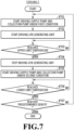
Fig. 7 is a flowchart illustrating the processes in the UFB generating step (S504) in the process of generating a UFB-containing liquid illustrated inFig. 5 in the present embodiment. - Upon start of the UFB generating step, in S701, the
CPU 2001 drives thesupply pump 703 and thecollection pump 704 under the first condition to circulate the liquid W through the circulation path B. Then, in S702, theCPU 2001 drives theUFB generating unit 1000. After that, in S703, theCPU 2001 determines whether the value of thetemperature sensors 1107 has reached a preset upper limit value and, if not, repeats the UFB generation and the determination until the value reaches the upper limit value. If the value of thetemperature sensors 1107 reaches the upper limit value, theCPU 2001 moves to S704 and stops driving theUFB generating unit 1000. - In S705, the
CPU 2001 switches thesupply pump 703 and thecollection pump 704 from the first condition to the second condition and drives them in the second condition. As a result, theUFB generating unit 1000 is cooled. After that, in S706, theCPU 2001 determines whether the value of thetemperature sensors 1107 has reached a preset lower limit value and, if not, repeats the determination until the value reaches the lower limit value. At this time, theUFB generating unit 1000 is not driven. If the value of thetemperature sensors 1107 reaches the lower limit value, theCPU 2001 moves to S707 and determines whether the density of UFBs in the UFB-containing liquid inside the storingchamber 900 has reached a predetermined density based on the detection value of theUFB density sensor 906. TheCPU 2001 returns S701 and repeats the processes if the density has not reached the predetermined density. TheCPU 2001 terminates the process if the density has reached the predetermined density. - While the driving can be switched as soon as the
temperature sensors 1107 output a value exceeding the upper limit or falling below the lower limit, the driving can be switched after confirming that thetemperature sensors 1107 has output a value exceeding the upper limit or falling below the lower limit for a certain time (e.g., about 0.5 second) taking into account the effect of noise. -
Figs. 8A and 8B are graphs illustrating temperature rise profiles obtained by actually measuring the temperature of theUFB generating unit 1000 based on the temperature detected by thetemperature sensors 1107 with the upper limit temperature set at 50°C and the lower limit temperature set at 35°C as an example of the second embodiment.Fig. 8A illustrates a temperature profile at short time intervals, andFig. 8B illustrates a temperature profile at long time intervals. Thetemperature sensors 1107, which are attached to theheating element substrate 1100, actually measure the temperature of theheating element substrate 1100, but the temperature will be described in the following as the temperature of theUFB generating unit 1000 including theheating element substrate 1100. - As illustrated in
Fig. 8A , it can be seen that the temperature of theUFB generating unit 1000 is held within a range of approximately 35 to 50°C while defining a pectinate profile, and is controlled to be within a desired temperature range even after being continuously driven for more than 10 hours. - In the present embodiment, the driving of the
supply pump 703, thecollection pump 704, and theUFB generating unit 1000 is controlled based on the value of the temperature sensors. For this reason, a table in which driving frequencies and driving times are associated with each other does not need to be stored in the ROM in advance as described in the first embodiment, and UFBs can be generated freely under a desired condition. - Incidentally, in a case of driving the
heating elements 1102 for a long time, the temperature rise characteristics can change over time. However, with the method in which the driving is controlled according to the value of thetemperature sensors 1107 as in the present embodiment, not according to the driving time of the heating elements, it is possible to accurately maintain the temperature of theUFB generating unit 1000 within a predetermined range without being affected by the temporal changes. - For the
UFB generating unit 1000, on which multipleheating element substrates 1100 are mounted as illustrated inFig. 2 , the values of multiple sets oftemperature sensors 1107 are read. In this case, the driving can be controlled based on an average value of the values of the sets of sensors. Alternatively, the highest value among the values of the multiple sets of sensors can be employed as the set upper limit temperature, and the lowest value among the values of the multiple sets of sensors can be employed as the set lower limit temperature. - A third embodiment of the present disclosure will be described below with reference to drawings. Note that the basic configuration in the present embodiment is similar to that in the first embodiment, and the characteristic configuration will therefore be described below. In the present embodiment, a process of removing bubbles generated inside and/or having entered the
UFB generating unit 1000 is performed as a process in the UFB generating step. -
Fig. 9A is a flowchart illustrating the UFB generating step in the present embodiment.Fig. 9B is a flowchart illustrating processes in S901 inFig. 9A. Fig. 9C is a flowchart illustrating processes in S903 inFig. 9A . The UFB generating step in the present embodiment will be described below using the flowcharts ofFigs. 9A to 9C . - First, the flowchart of
Fig. 9A will be described. Upon start of the UFB generating step, theCPU 2001 performs a first sequence in S901. Details of the first sequence will be described below. Then, in S902, theCPU 2001 determines whether the first sequence has been performed a predetermined number of times. If the first sequence has not been performed the predetermined number of times, theCPU 2001 returns to S901 and repeats the first sequence. If the first sequence has been performed the predetermined number of times, theCPU 2001 moves to S903 and performs a second sequence. Details of the second sequence will be described below. Thereafter, in S904, theCPU 2001 determines whether the density of UFBs in the UFB-containing liquid inside the storingchamber 900 has reached a predetermined density based on the detection value of theUFB density sensor 906. TheCPU 2001 returns S901 and repeats the processes if the density has not reached the predetermined density. TheCPU 2001 terminates the process if the density has reached the predetermined density. - The first sequence in S901 in
Fig. 9A will be described using the flowchart ofFig. 9B . Upon start of the UFB generating step, in S911, theCPU 2001 drives thesupply pump 703 and thecollection pump 704 under the first condition to circulate the liquid W through the circulation path B. Then, in S912, theCPU 2001 drives theUFB generating unit 1000. After that, in S913, theCPU 2001 determines whether the value of thetemperature sensors 1107 has reached a preset upper limit value and, if not, repeats the UFB generation and the determination until the value reaches the upper limit value. If the value of thetemperature sensors 1107 reaches the upper limit value, theCPU 2001 moves to S914 and stops driving theUFB generating unit 1000. - In S915, the
CPU 2001 switches thesupply pump 703 and thecollection pump 704 from the first condition to the second condition and drives them in the second condition. As a result, theUFB generating unit 1000 is cooled. After that, in S916, theCPU 2001 determines whether the value of thetemperature sensors 1107 has reached a preset lower limit value and, if not, repeats the determination until the value reaches the lower limit value. At this time, theUFB generating unit 1000 is not driven. If the value of thetemperature sensors 1107 reaches the lower limit value, theCPU 2001 terminates the process. - The second sequence in S903 in
Fig. 9A will be described using the flowchart ofFig. 9C . - Upon start of the second sequence, the
CPU 2001 drives thesupply pump 703 and thecollection pump 704 under the first condition to circulate the liquid in S921. Then, in S922, theCPU 2001 drives theUFB generating unit 1000 for a predetermined time. After that, theCPU 2001 stops driving theUFB generating unit 1000 in S923 and stops driving thesupply pump 703 in S924. Then, theCPU 2001 closes thevalve 1003 in S925. Next, in S926, theCPU 2001 switches thecollection pump 704 to the second condition and drives it under the second condition for a predetermined time with thevalve 1003 closed to thereby suck out all of the liquid W inside the UFB generating unit 1000 (third mode). In this way, bubbles generated inside and/or having entered theUFB generating unit 1000 are removed. Thereafter, in S927, theCPU 2001 opens thevalve 1003. Opening thevalve 1003 fills the inside of theUFB generating unit 1000 with the liquid W. - It is possible to remove the bubbles even in a case where the second condition in S926 in the present embodiment is the same as the first condition. However, the flow velocity under the second condition in S926 is desirably set to be higher than that under the first condition so that the liquid W inside the
UFB generating unit 1000 can be sucked out in a shorter time. This minimizes the time for which the UFB generation is stopped, and thus enables efficient UFB generation. - As described above, not only the temperature of the
UFB generating unit 1000 is maintained within a predetermined range, but also bubbles are removed. This prevents the bubbles from obstructing the bubble generation and enables more stable production of a UFB-containing liquid. - While the present disclosure has been described with reference to exemplary embodiments, it is to be understood that the disclosure is not limited to the disclosed exemplary embodiments. The scope of the following claims is to be accorded the broadest interpretation so as to encompass all such modifications and equivalent structures and functions.
- An ultrafine bubble-containing liquid producing apparatus (2000) and method enables preventing ultrafine bubbles over a long period of operation by, based on a predetermined condition, switching between a first mode where a liquid between an ultrafine bubble generating unit (1000) and a storing chamber (900) is circulated at a first flow velocity and a second mode where the liquid is circulated at a second flow velocity higher than the first flow velocity.
Claims (17)
- An ultrafine bubble-containing liquid producing apparatus (2000) comprising:an ultrafine bubble generating unit (1000) configured to generate ultrafine bubbles inside a liquid;a circulating unit configured to circulate the liquid through a circulation path including the ultrafine bubble generating unit (1000); anda control unit configured to control the ultrafine bubble generating unit (1000) and the circulating unit,wherein the control unit, based on a predetermined condition, switches between a first mode where the liquid in the circulation path is circulated at a first flow velocity and a second mode where the liquid in the circulation path is circulated at a second flow velocity higher than the first flow velocity.
- The ultrafine bubble-containing liquid producing apparatus (2000) according to claim 1, wherein the predetermined condition is a time for which the ultrafine bubble generating unit (1000) is driven.
- The ultrafine bubble-containing liquid producing apparatus (2000) according to claim 1, further comprising a temperature detecting unit that detects temperature of the ultrafine bubble generating unit, wherein the predetermined condition is the detected temperature.
- The ultrafine bubble-containing liquid producing apparatus (2000) according to claim 3, wherein the control unit switches to the second mode from the first mode in a case where the detected temperature reaches a predetermined upper limit temperature.
- The ultrafine bubble-containing liquid producing apparatus (2000) according to claim 3, wherein the ultrafine bubble generating unit (1000) includes a plurality of the temperature detecting units, and
the control unit switches to the second mode from the first mode in a case where an average value of the detected temperatures reaches a predetermined upper limit temperature. - The ultrafine bubble-containing liquid producing apparatus (2000) according to claim 3, whereinthe ultrafine bubble generating unit (1000) includes a plurality of the temperature detecting units, andthe control unit switches to the second mode from the first mode in a case where a highest temperature from among the detected temperatures reaches a predetermined upper limit temperature.
- The ultrafine bubble-containing liquid producing apparatus (2000) according to claim 3, wherein the control unit terminates an operation in the second mode in a case where the detected temperature reaches a predetermined lower limit temperature.
- The ultrafine bubble-containing liquid producing apparatus (2000) according to claim 3, whereinthe ultrafine bubble generating unit includes a plurality of the temperature detecting units, andthe control unit executes an operation in the second mode in a case where an average value of the detected temperatures reaches a predetermined lower limit temperature.
- The ultrafine bubble-containing liquid producing apparatus (2000) according to claim 3, whereinthe ultrafine bubble generating unit (1000) includes a plurality of the temperature detecting units, andthe control unit executes an operation in the second mode in a case where a lowest temperature from among the detected temperatures reaches a predetermined lower limit temperature.
- The ultrafine bubble-containing liquid producing apparatus (2000) according to claim 1, wherein the circulating unit includes:a circulation unit that is disposed downstream of the ultrafine bubble generating unit (1000) in the circulation path and is configured to circulate the liquid in the circulation path, anda closing unit (1003) that is disposed upstream of the ultrafine bubble generating unit (1000) in the circulation path and is configured to switch between closing and opening the circulation path, andthe control unit executes a third mode where the control unit drives the circulation unit while driving of the ultrafine bubble generating unit (1000) is stopped and the closing unit (1003) is closed.
- The ultrafine bubble-containing liquid producing apparatus (2000) according to claims 1 to 10, further comprising a storing unit (900) disposed at an intermediate portion of the circulation path that is configured to store the liquid.
- The ultrafine bubble-containing liquid producing apparatus (2000) according to claim 11, further comprising an agitating unit configured to agitate the stored liquid.
- The ultrafine bubble-containing liquid producing apparatus (2000) according to claim 11 or 12, further comprising a density detecting unit (906) configured to detect density of ultrafine bubbles in the stored liquid.
- The ultrafine bubble-containing liquid producing apparatus (2000) according to claims 11 to 13, further comprising a temperature control unit configured to control temperature of the stored liquid.
- The ultrafine bubble-containing liquid producing apparatus (2000) according to claims 1 to 14, wherein the ultrafine bubble generating unit (1000) generates ultrafine bubbles by film boiling caused at an interface between the liquid and a heating element (1102) by causing the heating element (1102) to generate heat.
- The ultrafine bubble-containing liquid producing apparatus (2000) according to claims 1 to 15, further comprising a dissolving unit (800) configured to dissolve a predetermined gas into the liquid to be circulated through the circulation path.
- A method for producing an ultrafine bubble-containing liquid, the method comprising:generating ultrafine bubbles inside a liquid;circulating the liquid through a circulation path; andswitching, based on a predetermined condition, between a first mode where the liquid in the circulation path is circulated at a first flow velocity and a second mode where the liquid in the circulation path is circulated at a second flow velocity higher than the first flow velocity.
Applications Claiming Priority (1)
| Application Number | Priority Date | Filing Date | Title |
|---|---|---|---|
| JP2022212045A JP2024095045A (en) | 2022-12-28 | 2022-12-28 | Apparatus and method for producing ultra-fine bubble-containing liquid |
Publications (1)
| Publication Number | Publication Date |
|---|---|
| EP4397400A1 true EP4397400A1 (en) | 2024-07-10 |
Family
ID=89321733
Family Applications (1)
| Application Number | Title | Priority Date | Filing Date |
|---|---|---|---|
| EP23219845.7A Pending EP4397400A1 (en) | 2022-12-28 | 2023-12-22 | Ultrafine bubble-containing liquid producing apparatus and method |
Country Status (4)
| Country | Link |
|---|---|
| US (1) | US20240216877A1 (en) |
| EP (1) | EP4397400A1 (en) |
| JP (1) | JP2024095045A (en) |
| CN (1) | CN118253206A (en) |
Citations (3)
| Publication number | Priority date | Publication date | Assignee | Title |
|---|---|---|---|---|
| JP2015181976A (en) | 2014-03-20 | 2015-10-22 | Idec株式会社 | Fine bubble liquid generation device |
| JP2019042732A (en) | 2017-08-31 | 2019-03-22 | キヤノン株式会社 | Method of producing ultra fine bubble, apparatus for producing ultra fine bubble containing liquid, method of producing ultra fine bubble containing liquid |
| EP3816117A1 (en) * | 2019-10-31 | 2021-05-05 | Canon Kabushiki Kaisha | Ultrafine bubble-containing liquid producing apparatus and ultrafine bubble-containing liquid producing method |
-
2022
- 2022-12-28 JP JP2022212045A patent/JP2024095045A/en active Pending
-
2023
- 2023-12-20 US US18/391,097 patent/US20240216877A1/en active Pending
- 2023-12-22 EP EP23219845.7A patent/EP4397400A1/en active Pending
- 2023-12-25 CN CN202311793164.XA patent/CN118253206A/en not_active Withdrawn
Patent Citations (3)
| Publication number | Priority date | Publication date | Assignee | Title |
|---|---|---|---|---|
| JP2015181976A (en) | 2014-03-20 | 2015-10-22 | Idec株式会社 | Fine bubble liquid generation device |
| JP2019042732A (en) | 2017-08-31 | 2019-03-22 | キヤノン株式会社 | Method of producing ultra fine bubble, apparatus for producing ultra fine bubble containing liquid, method of producing ultra fine bubble containing liquid |
| EP3816117A1 (en) * | 2019-10-31 | 2021-05-05 | Canon Kabushiki Kaisha | Ultrafine bubble-containing liquid producing apparatus and ultrafine bubble-containing liquid producing method |
Also Published As
| Publication number | Publication date |
|---|---|
| US20240216877A1 (en) | 2024-07-04 |
| JP2024095045A (en) | 2024-07-10 |
| CN118253206A (en) | 2024-06-28 |
Similar Documents
| Publication | Publication Date | Title |
|---|---|---|
| US11338587B2 (en) | Fluid circulation apparatus and fluid ejection apparatus | |
| US8926077B2 (en) | Ink supply system for ink jet printers | |
| US9205665B2 (en) | Inkjet apparatus using piezoelectric pump | |
| US11179945B2 (en) | Liquid supply device and liquid discharge device | |
| US8292396B2 (en) | Image forming apparatus which adjusts ink temperature | |
| CN109070075B (en) | Microfluidic device with capillary chamber | |
| US10272692B2 (en) | Liquid circulation device, liquid ejection apparatus, and liquid ejection method | |
| JP5776447B2 (en) | Control device and excision device used in connection with fluid ejection device for excising biological tissue by ejected fluid | |
| CN106256551A (en) | Circulating device for ink and inkjet recording device | |
| US10343414B2 (en) | Liquid circulation device, liquid discharge device and liquid discharge method | |
| JP2006075683A (en) | Liquid coating apparatus and liquid degassing method thereof | |
| KR20140075118A (en) | Ink circulation apparatus, inkjet printer having the same | |
| EP4397400A1 (en) | Ultrafine bubble-containing liquid producing apparatus and method | |
| CN108569033A (en) | Circulator and liquid ejection apparatus | |
| EP4219171B1 (en) | Liquid circulating device and liquid ejecting device | |
| CN110154527A (en) | Liquid circulation device and liquid ejection device | |
| JP6672002B2 (en) | Liquid ejection device and control method | |
| US20240216876A1 (en) | Manufacturing apparatus and manufacturing method for ultra fine bubble containing liquid | |
| JP2011033277A (en) | Cooling device | |
| JP2016052768A (en) | Ink circulating device cleaning device and ink circulating device cleaning method | |
| JP2009034950A (en) | Image formation device | |
| JP7550349B2 (en) | Inkjet head | |
| JP2025132580A (en) | Fine bubble-containing liquid manufacturing device, fine bubble-containing liquid concentrating device, and fine bubble-containing liquid manufacturing method | |
| JP3987477B2 (en) | Mold temperature controller | |
| JP2015116753A (en) | Inkjet recording device |
Legal Events
| Date | Code | Title | Description |
|---|---|---|---|
| PUAI | Public reference made under article 153(3) epc to a published international application that has entered the european phase |
Free format text: ORIGINAL CODE: 0009012 |
|
| STAA | Information on the status of an ep patent application or granted ep patent |
Free format text: STATUS: THE APPLICATION HAS BEEN PUBLISHED |
|
| AK | Designated contracting states |
Kind code of ref document: A1 Designated state(s): AL AT BE BG CH CY CZ DE DK EE ES FI FR GB GR HR HU IE IS IT LI LT LU LV MC ME MK MT NL NO PL PT RO RS SE SI SK SM TR |
|
| STAA | Information on the status of an ep patent application or granted ep patent |
Free format text: STATUS: REQUEST FOR EXAMINATION WAS MADE |
|
| 17P | Request for examination filed |
Effective date: 20250110 |
|
| STAA | Information on the status of an ep patent application or granted ep patent |
Free format text: STATUS: EXAMINATION IS IN PROGRESS |
|
| 17Q | First examination report despatched |
Effective date: 20251127 |
|
| STAA | Information on the status of an ep patent application or granted ep patent |
Free format text: STATUS: THE APPLICATION HAS BEEN WITHDRAWN |