EP4397385A2 - Ride systems having dynamic ride vehicle movement - Google Patents
Ride systems having dynamic ride vehicle movement Download PDFInfo
- Publication number
- EP4397385A2 EP4397385A2 EP24177274.8A EP24177274A EP4397385A2 EP 4397385 A2 EP4397385 A2 EP 4397385A2 EP 24177274 A EP24177274 A EP 24177274A EP 4397385 A2 EP4397385 A2 EP 4397385A2
- Authority
- EP
- European Patent Office
- Prior art keywords
- ride
- movement
- vehicle
- vehicles
- rider
- Prior art date
- Legal status (The legal status is an assumption and is not a legal conclusion. Google has not performed a legal analysis and makes no representation as to the accuracy of the status listed.)
- Granted
Links
Images






Classifications
-
- A—HUMAN NECESSITIES
- A63—SPORTS; GAMES; AMUSEMENTS
- A63G—MERRY-GO-ROUNDS; SWINGS; ROCKING-HORSES; CHUTES; SWITCHBACKS; SIMILAR DEVICES FOR PUBLIC AMUSEMENT
- A63G31/00—Amusement arrangements
- A63G31/02—Amusement arrangements with moving substructures
-
- A—HUMAN NECESSITIES
- A63—SPORTS; GAMES; AMUSEMENTS
- A63G—MERRY-GO-ROUNDS; SWINGS; ROCKING-HORSES; CHUTES; SWITCHBACKS; SIMILAR DEVICES FOR PUBLIC AMUSEMENT
- A63G31/00—Amusement arrangements
- A63G31/16—Amusement arrangements creating illusions of travel
-
- A—HUMAN NECESSITIES
- A63—SPORTS; GAMES; AMUSEMENTS
- A63G—MERRY-GO-ROUNDS; SWINGS; ROCKING-HORSES; CHUTES; SWITCHBACKS; SIMILAR DEVICES FOR PUBLIC AMUSEMENT
- A63G33/00—Devices allowing competitions between several persons, not otherwise provided for
-
- G—PHYSICS
- G05—CONTROLLING; REGULATING
- G05B—CONTROL OR REGULATING SYSTEMS IN GENERAL; FUNCTIONAL ELEMENTS OF SUCH SYSTEMS; MONITORING OR TESTING ARRANGEMENTS FOR SUCH SYSTEMS OR ELEMENTS
- G05B15/00—Systems controlled by a computer
- G05B15/02—Systems controlled by a computer electric
Definitions
- the present disclosure relates generally to ride systems. More specifically, embodiments of the present disclosure relate to ride systems having ride vehicles that may move about a coordinated ride path in multiple directions relative to one another. The movement of the ride vehicles may be dynamically adjusted based on received inputs, such as inputs provided by riders of the ride vehicles.
- a ride system includes one or more ride vehicles.
- Each ride vehicle of the one or more ride vehicles includes a rider support configured to carry a rider, a support actuator coupled to the rider support and to a base of the ride vehicle, a ride vehicle movement system coupled to the base and configured to move the ride vehicle to traverse a ride area, and a roll system configured to move the rider support or the base angularly relative to the ride area.
- the support actuator is configured to move the rider support relative to the base.
- a ride system in an embodiment, includes a track and a ride vehicle configured to travel along the track.
- the ride vehicle includes a plurality of rider supports, where each rider support of the plurality of rider supports is configured to carry a respective rider.
- the ride vehicle also includes a plurality of support actuators, where each support actuator is coupled to a respective rider support of the plurality of rider supports and a base of the ride vehicle, and each support actuator is configured to move the respective rider support relative to the base.
- the ride vehicle includes a ride vehicle movement system integrated with the base and configured to move the ride vehicle along the track and a roll system configured to move the base and the plurality of rider supports angularly relative to the track.
- the ride vehicles may include mechanisms and portions (e.g., the rider supports) that may move vertically with respect to a surface of the ride area and/or with respect to a base of the ride vehicle, horizontally in various directions (e.g., may move in any planar direction, may spin, may turn, and so forth), and that may roll (e.g., lean and/or move angularly with respect to the surface of the ride area and/or with respect to the base of the ride vehicle).
- mechanisms and portions e.g., the rider supports
- the rider supports may move vertically with respect to a surface of the ride area and/or with respect to a base of the ride vehicle, horizontally in various directions (e.g., may move in any planar direction, may spin, may turn, and so forth), and that may roll (e.g., lean and/or move angularly with respect to the surface of the ride area and/or with respect to the base of the ride vehicle).
- the ride system and/or the ride vehicles may include a control system that controls movement of the ride vehicles within the ride area. For example, based on a position of a ride vehicle with respect to a ride path (e.g., based on an actual position of the ride vehicle relative to an intended position of the ride vehicle along the ride path), the control system may adjust a trajectory or traveled course of the ride vehicle.
- certain factors may affect the trajectory of the ride vehicle, such as obstacles within the ride area, a weight of the rider on the ride vehicle, a weight of other items disposed on or part of the ride vehicle, obstructions attached to the ride vehicle that may be dragging behind, in front of, or to the side of the ride vehicle, rider inputs (e.g., a rider shifting their weight, a rider turning a steering wheel or adjusting the trajectory of the ride vehicle generally, a rider adjusting a speed of the ride vehicle, etc.).
- rider inputs e.g., a rider shifting their weight, a rider turning a steering wheel or adjusting the trajectory of the ride vehicle generally, a rider adjusting a speed of the ride vehicle, etc.
- the control system may adjust the trajectory or the traveled course of the ride vehicle to generally follow the ride path and to account for such factors.
- the ride vehicles of the ride system may include a selected ride vehicle configured to lead the other ride vehicles.
- a rider riding the selected ride vehicle may provide an input, such as by shifting their weight, controlling a joystick or other hand controller, pressing a button, or a combination thereof.
- a controller of the selected ride vehicle and/or of the ride system may adjust the trajectory of the selected ride vehicle and/or movement of the rider support of the selected ride vehicle. For example, if the rider of the selected ride vehicle provides an input indicative of pulling the rider support of the selected ride vehicle upwardly and leaning the rider support toward the left, the controller may adjust the movement of the selected ride vehicle from the planned and choreographed ride path to generally move the rider support upwardly and to the left.
- the ride system controller may adjust the movement of some or all of the other ride vehicles and/or the rider supports of the other ride vehicles within the ride system.
- the adjustments to the movements of the other ride vehicles may generally correspond to the movement of the selected ride vehicle (e.g., may be based on a correlative adjustment/movement of the selected ride vehicle or portions thereof), may mirror the movement of the selected ride vehicle, and/or may be of a varying/different degree relative to the movement of the selected ride vehicle.
- the designation of the selected ride vehicle among the ride vehicles of the ride system may change during operation of the ride system.
- the selected ride vehicle in a first time period during a ride sequence of the ride system (e.g., a time sequence of operation of the ride system), the selected ride vehicle may be a first ride vehicle, and in a second time period during the ride sequence, the selected ride vehicle may be a second, different ride vehicle.
- the ride system allows the one or multiple riders of the ride system to at least partially control the ride vehicles during the ride sequence and while the riders ride the ride vehicles.
- the ride system may dynamically adjust the movement of the ride vehicles based on the rider input.
- the ride system may also include an auditory system configured to provide an auditory experience (e.g., sound effects, music, etc.) that generally corresponds to the choreographed movement of the ride vehicles and/or that may be adjusted based on the input provided at the ride vehicles.
- an auditory system configured to provide an auditory experience (e.g., sound effects, music, etc.) that generally corresponds to the choreographed movement of the ride vehicles and/or that may be adjusted based on the input provided at the ride vehicles.
- the ride system may include a ride station configured to dock/accommodate the ride vehicles.
- the ride system may dispatch some or all of the ride vehicles from the ride station during operation.
- the number of ride vehicles dispatched from the ride station may generally depend on a party size (e.g., one rider, two riders, three riders, four riders, six riders, ten riders, etc.) that is riding, or are about to ride, the ride vehicles of the ride system.
- the ride system may include a ride vehicle configured to move along a fixed track and that includes one or multiple rider supports configured to be ridden by multiple riders.
- each rider support may be coupled to a base of the ride vehicle, and the base may move along the track.
- Each rider support may move relative to the base and relative to one another as the ride vehicle moves along the track. The movement of each rider support may be planned and/or choreographed based on the position of the ride vehicle along the track.
- the ride vehicle may include a selected rider support configured to receive an input from a rider, and a controller of the ride system may control the movement of the selected rider support and/or other rider supports of the ride vehicle based on the input, such as by adjusting the planned and/or choreographed movement of the rider supports.
- a controller of the ride system may control the movement of the selected rider support and/or other rider supports of the ride vehicle based on the input, such as by adjusting the planned and/or choreographed movement of the rider supports.
- FIG. 1 is a rear perspective view of an embodiment of a ride system 10 including ride vehicles 12.
- each ride vehicle 12 and certain components of the ride vehicles 12 may be described with reference to a vertical axis or direction 14, a longitudinal axis or direction 16, and a lateral axis or direction 18.
- each ride vehicle 12 includes a base 20 and a rider support 22 (e.g., a riding assembly) coupled to the base 20 via a linkage assembly 24.
- the base 20 may move the ride vehicle 12 along a ride path and/or along a surface 26 of a ride area 28 of the ride system 10, and the rider support 22 may carry a rider (e.g., a user) of the ride vehicle 12.
- the rider may ride the ride vehicle 12 for entertainment and/or transportation purposes.
- the rider support 22 and/or the ride vehicle 12 may include ornamental features that enhance the rider's experience, such as features resembling an animal, a fictional character, an automobile, decorations, and/or other objects.
- the illustrated embodiment of the ride system 10 includes three ride vehicles 12, certain embodiments of the ride system 10 may include more or fewer ride vehicles 12 (e.g. one ride vehicle 12, two ride vehicles 12, four ride vehicles 12, five ride vehicles 12, eight ride vehicles 12, etc.).
- the ride vehicles 12 may share a common base 20.
- the common base 20 may be significantly wider than the illustrated bases 20 of FIG. 1 such that the common base 20 may accommodate multiple rider supports 22 and multiple linkage assemblies 24.
- each ride vehicle 12 may move along a choreographed ride path within the ride system 10 (e.g., along the surface 26 of the ride area 28) and/or may include mechanisms that enable the ride vehicles 12 and/or the rider supports 22 to move vertically (e.g., generally along the vertical axis 14), to move horizontally (e.g., generally along the longitudinal axis 16 and/or the lateral axis 18), and to roll while moving along the ride path (e.g., to rotate generally about the longitudinal axis 16 and/or the lateral axis 18).
- a choreographed ride path within the ride system 10 e.g., along the surface 26 of the ride area 28
- each ride vehicle 12 may move along a choreographed ride path within the ride system 10 (e.g., along the surface 26 of the ride area 28) and/or may include mechanisms that enable the ride vehicles 12 and/or the rider supports 22 to move vertically (e.g., generally along the vertical axis 14), to move horizontally (e.
- each rider may at least partially control/alter the movement of the ride vehicles 12 and/or the rider supports 22.
- the movement of the ride vehicles 12 along the choreographed ride path, in the various directions while moving along the ride path, and the ability of the riders to at least partially control the movements of the ride vehicles 12 and/or the rider supports 22 may provide an interactive and entertaining experience for the riders.
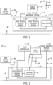
- FIG. 2 is a block diagram of an embodiment of the ride system 10 of FIG. 1 including the ride vehicle 12.
- the ride system 10 includes a ride control system 30 in communication with a ride vehicle control system 32 of the ride vehicle 12.
- the ride control system 30 and the ride vehicle control system 32 are communicatively coupled via a wireless connection 34 (e.g., Wi-Fi, Bluetooth, etc.).
- the ride control system 30 and the ride vehicle control system 32 may be communicatively coupled via a wired connection (e.g., Ethernet, universal serial bus (USB), CANbus, ISObus, etc.).
- a wired connection e.g., Ethernet, universal serial bus (USB), CANbus, ISObus, etc.
- the ride vehicle 12 includes a rider support movement system 40 (e.g., a riding assembly movement system), a ride vehicle movement system 42, and a roll system 44 communicatively coupled to the ride vehicle control system 32, such that the ride vehicle control system 32 may control the rider support movement system 40, the ride vehicle movement system 42, and the roll system 44.
- the rider support movement system 40, the ride vehicle movement system 42, and/or the roll system 44 may be directly communicatively coupled to the ride control system 30, such that the ride control system 30 may control the rider support movement system 40, the ride vehicle movement system 42, and/or the roll system 44.
- the rider support movement system 40 may move the rider support 22 with respect to the base 20 and/or along the vertical axis 14 and/or the longitudinal axis 16.
- the ride vehicle movement system 42 may move the ride vehicle 12 along the surface 26 of the ride area 28 of the ride system 10 generally along the longitudinal axis 16 and/or the lateral axis 18.
- the ride vehicle movement system 42 may move the ride vehicle 12 in any planar direction (e.g., along a plane parallel to the surface 26 of the ride area 28), may turn the ride vehicle 12, and may spin the ride vehicle 12.
- the roll system 44 may roll or angle the ride vehicle 12 (e.g., move the ride vehicle 12 generally angularly and/or tilt the ride vehicle 12) and/or the rider support 22 relative to the surface 26 of the ride area 28 of the ride system 10 and generally about the longitudinal axis 16.
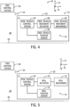
- FIG. 3 is a block diagram of an embodiment of the ride system 10 of FIG. 1 including the rider support movement system 40 of the ride vehicle 12.
- the rider support movement system 40 may move the rider support 22 generally along the vertical axis 14 and/or along the longitudinal axis 16. Additionally, the rider support movement system 40 may move the rider support 22 with respect to the base 20 and/or the surface 26 of the ride area 28 of the ride system 10.
- the rider support movement system 40 includes the linkage assembly 24, a support actuator 50, a rider support position sensor 52, and a rider controller 54.
- the support actuator 50 is configured to actuate to cause the linkage assembly 24 to move the rider support 22 relative to the base 20 and/or the surface 26 of the ride area 28.
- the support actuator 50 may be a piston, a hydraulic cylinder, a pneumatic cylinder, another suitable actuator, or the like, and may be coupled to the linkage assembly 24.
- the linkages 56 of the linkage assembly 24 may rotate relative to one another (e.g., via a pivot point at which the linkages 56 are coupled) to cause the rider support 22 to move relative to the base 20 and/or the surface 26 of the ride area 28.
- a first linkage 56 may be coupled to the support actuator 50 and to a second linkage 56.
- the support actuator 50 may move the first linkage 56, which may cause movement of the second linkage 56 and the rider support 22.
- the linkage assembly 24 may include additional mechanisms to enable/cause the movement of the rider support 22 generally along the vertical axis 14 and/or along the longitudinal axis 16, such as a pin connecting the linkages 56, an additional actuator coupled to and/or configured to move both the linkages 56, and other suitable mechanisms.
- the vertical and/or longitudinal motion caused by the rider support movement system 40 may be combined with the movement caused by the ride vehicle movement system 42 and/or the roll movement caused by the roll system 44.
- the rider support movement system 40 may include movement mechanisms in addition to or in place of the linkage assembly 24 and/or the support actuator 50 configured to move the rider support 22 relative to the base 20 and/or the surface 26 of the ride area 28.
- the ride vehicle control system 32 may adjust the vertical and/or longitudinal position of the rider support 22 relative to the base 20 and/or the surface 26 of the ride area 28. For example, the ride vehicle control system 32 may output a signal to the support actuator 50 to actuate to cause the linkage assembly 24 to move the rider support 22.
- the support actuator 50 may be omitted or may be integral to the linkage assembly 24, such that the ride vehicle control system 32 may communicate directly with the linkage assembly 24 to cause the linkage assembly 24 to move the rider support 22.
- the ride control system 30 may communicate directly with the linkage assembly 24, or portions thereof, to control the movement of the rider support 22.
- the ride control system 30 may control vertical and/or longitudinal movement of the rider support 22 of the ride vehicle 12 based on respective positions of other rider supports 22 of other ride vehicles 12. For example, based on another rider support 22 of another, separate ride vehicle 12 being at a first position, the ride control system 30 may control the movement/position of the rider support 22 of the ride vehicle 12. As such, the ride control system 30 may control the movement/position of the rider support 22 of each ride vehicle 12 individually (e.g., independently, separately, and/or differently).
- the rider controller 54 is coupled to the rider support 22 and communicatively coupled to the ride vehicle control system 32.
- the rider controller 54 may be any suitable controller configured to receive an input from the rider indicative of adjustment to the movement and/or position of the rider support 22, such as a joystick, a gaming controller, or another type of hand controller.
- the rider controller 54 may be integral to the rider support 22, such as included in handlebars of the rider support 22 (e.g., the rider may provide an input by moving the handlebars, by pressing button(s) on the handlebars, or turning certain mechanisms of the handlebars), included in a body of the rider support 22 (e.g., the rider may shift their weight to provide an input), or incorporated into the rider support 22 in other manners.
- the rider controller 54, or the ride vehicle 12 generally, may include sensors configured to detect the rider shifting their weight while positioned on the rider support 22, such as inertial sensors, accelerometers, pressure sensors, and/or other sensors configured to detect a shift in weight and/or a shift in weight distribution.
- the rider controller 54 may provide an interactive experience for a rider positioned on the rider support 22 by allowing the rider to at least partially control the movement/position of the rider support 22 and/or the ride vehicle 12.
- FIG. 4 is a block diagram of a side view of an embodiment of the ride system 10 of FIG. 1 including the ride vehicle movement system 42 of the ride vehicle 12.
- the ride vehicle movement system 42 may move the ride vehicle 12 generally along the longitudinal axis 16 and/or the lateral axis 18 and in any planar direction.
- the ride vehicle movement system 42 may also turn and/or spin the ride vehicle 12 along the surface 26 of the ride area 28 of the ride system 10.
- the ride vehicle movement system 42 may turn the ride vehicle 12 in a first direction while spinning the ride vehicle 12 in a second direction.
- the ride vehicle movement system 42 may turn the ride vehicle 12 toward the left while spinning the ride vehicle 12 to the right (e.g., while spinning the ride vehicle 12 clockwise if viewed from a top view).
- the ride vehicle movement system 42 includes a ride vehicle movement actuator 60, a ride vehicle movement mechanism 62, and a ride vehicle position sensor 64.
- the ride vehicle movement actuator 60 may actuate to cause the ride vehicle movement mechanism 62 to move the ride vehicle 12.
- the ride vehicle movement actuator 60 may be a piston, a hydraulic cylinder, a pneumatic cylinder, another suitable actuator, and the like, and may be coupled to the ride vehicle movement mechanism 62.
- the ride vehicle movement mechanism 62 may rotate, turn, or perform any other suitable movement to cause the ride vehicle 12 to move along the surface 26 of the ride area 28 of the ride system 10.
- the ride vehicle movement mechanism 62 may be wheels, spheres (e.g., steel or rubber balls), a track system, another suitable movement mechanism, or a combination thereof.
- the ride vehicle 12 may include more or fewer ride vehicle movement mechanisms 62 (e.g., two ride vehicle movement mechanisms 62, three ride vehicle movement mechanisms 62, five ride vehicle movement mechanisms 62, etc.) configured to move the ride vehicle 12 along the surface 26 of the ride area 28.
- the motion caused by the ride vehicle movement system 42 may be combined with the rider support movement caused by the rider support movement system 40. For example, while the rider support 22 moves relative to the base 20 and/or the surface 26 of the ride area 28, the ride vehicle movement system 42 may turn, spin, or otherwise move the ride vehicle 12 along the surface 26 of the ride area 28 of the ride system 10.
- the ride vehicle position sensor 64 may output a signal indicative of a position of the ride vehicle 12 within the ride system 10.
- the ride vehicle position sensor 64 may sense a position of the ride vehicle 12 along the longitudinal axis 16, along the lateral axis 16, relative to another ride vehicle 12, relative to a ride path, relative to other portions of the ride system 10, along the surface 26 of the ride area 28, or the like, and output the signal indicative of the position of the ride vehicle 12.
- the ride vehicle control system 32 may receive the signal indicative of the position of the ride vehicle 12 from the ride vehicle position sensor 64. Based on the ride vehicle position of the ride vehicle 12, the ride vehicle control system 32 may adjust a trajectory (e.g., a course) of the ride vehicle 12 along the surface 26 of the ride area 28 of the ride system 10.
- FIG. 5 is a block diagram of a side view of an embodiment of the ride system 10 of FIG. 1 including the roll system 44 of the ride vehicle 12.
- the roll system 44 may move the ride vehicle 12 and/or the rider support 22 angularly relative to the surface 26 of the ride area 28 of the ride system 10.
- the roll system 44 includes a roll actuator 70, a roll mechanism 72, and a roll sensor 74.
- the roll actuator 70 is configured to actuate to cause the roll mechanism 72 to move the ride vehicle 12 and/or the rider support 22 generally angularly relative to the surface 26 of the ride area 28.
- the multiple/different choreographed routines allow the ride system 160 to provide varying experiences for the riders of the ride vehicles 162 and enhance a re-ridability appeal of the ride system 160. Additionally, some choreographed routines may not include all of the ride vehicles 162 of the ride system 160. For example, the ride system 160 may be configured to dispatch only a subset of the ride vehicles 162 based on the choreographed routine, among other factors (e.g., such as party size).
- the ride control system 30 sends the choreographed movement of each rider support 228 that corresponds to the choreographed routine of the ride system 220 to each rider support 228.
- the respective ride vehicle control system 32 of each rider support 228 may receive the choreographed movement and may control the rider support 228 based on the choreographed movement.
- the ride vehicle control system 32 of each rider support 228 may control the respective rider support movement system 240.
- the ride control system 30 may be directly communicatively coupled to and configured to control the rider support movement system 240 to follow the respective choreographed movements.
- the ride control system 30 may control the ride vehicle movement system 232 and/or the roll system 250 of the ride vehicle 224 based on the choreographed routine.
- control system may adjust a trajectory or traveled course of the ride vehicle.
- the ride system further comprises a display system configured to provide a cinematic presentation for viewing by the rider of each ride vehicle, and a controller configured to instruct the display system to provide the cinematic presentation, and control the support actuator, the ride vehicle movement system, and the roll system of each ride vehicle of the one or more ride vehicles individually based on a choreographed routine of the one or more ride vehicles that corresponds to the cinematic presentation and an input received from a selected ride vehicle of the one or more ride vehicles, wherein the input is indicative of an adjustment to the movement of the rider support, the ride vehicle, or both, of the selected ride vehicle, and wherein the one or more ride vehicles comprise a plurality of ride vehicles, wherein the choreographed routine comprises a designation of the selected ride vehicle of the plurality of ride vehicles based at least in part on a time sequence of the choreographed routine, and wherein the selected ride vehicle is a first ride vehicle of the plurality of ride vehicles in a first time period during the time sequence, and the selected ride vehicle is a second ride vehicle
- a ride system in an embodiment comprises a track, a ride vehicle configured to travel along the track, wherein the ride vehicle comprises a plurality of rider supports, wherein each rider support of the plurality of rider supports is configured to carry a respective rider, a plurality of support actuators, wherein each support actuator of the plurality of support actuators is coupled to a respective rider support of the plurality of rider supports and a base of the ride vehicle, and each support actuator of the plurality of support actuators is configured to move the respective rider support relative to the base, a ride vehicle movement system integrated with the base and configured to move the ride vehicle along the track, and a roll system configured to move the base and the plurality of rider supports angularly relative to the track.
- the controller is configured to control movement of one or more other rider supports of the plurality of rider supports different from the selected rider support based at least in part on the input received from the selected rider support.
Landscapes
- Engineering & Computer Science (AREA)
- General Engineering & Computer Science (AREA)
- Physics & Mathematics (AREA)
- General Physics & Mathematics (AREA)
- Automation & Control Theory (AREA)
- Motorcycle And Bicycle Frame (AREA)
- Vehicle Body Suspensions (AREA)
- Traffic Control Systems (AREA)
Abstract
Description
- This application claims priority from and the benefit of
U.S. Provisional Application Serial No. 62/865,766, entitled "RIDE SYSTEMS HAVING DYNAMIC RIDE VEHICLE MOVEMENT," filed June 24, 2019 - The present disclosure relates generally to ride systems. More specifically, embodiments of the present disclosure relate to ride systems having ride vehicles that may move about a coordinated ride path in multiple directions relative to one another. The movement of the ride vehicles may be dynamically adjusted based on received inputs, such as inputs provided by riders of the ride vehicles.
- Some ride vehicles are ridden by users for transportation and/or entertainment purposes. For example, some amusement rides and other structured ride systems include ride vehicles that move in patterns along fixed paths. During operation, the movement of the ride vehicles is typically restricted to the fixed paths. It is now recognized that such movement of the ride vehicles may detract from the users' experiences while riding the ride vehicles.
- This section is intended to introduce the reader to various aspects of art that may be related to various aspects of the present disclosure, which are described below. This discussion is believed to be helpful in providing the reader with background information to facilitate a better understanding of the various aspects of the present disclosure. Accordingly, it should be understood that these statements are to be read in this light, and not as admissions of prior art.
- Certain embodiments commensurate in scope with the originally claimed embodiments are summarized below. These embodiments are not intended to limit the scope of the claimed embodiments, but rather these embodiments are intended only to provide a brief summary of possible forms of the claimed embodiments. Indeed, the present disclosure may encompass a variety of forms that may be similar to or different from the embodiments set forth below.
- In an embodiment, a ride system includes a plurality of ride vehicles. Each ride vehicle of the plurality of ride vehicles includes a rider support configured to carry a rider, a support actuator coupled to the rider support and a base of the ride vehicle, and a ride vehicle movement system integrated with the base and configured to move the ride vehicle relative to a ride area, where the support actuator is configured to move the rider support relative to the base. The ride system also includes a controller configured to control the support actuator and the ride vehicle movement system of each ride vehicle of the plurality of ride vehicles individually based at least in part on instructions, stored in memory, for performing a choreographed routine of the plurality of ride vehicles, and an input received from a selected ride vehicle of the plurality of ride vehicles. The input is indicative of an adjustment to the support actuator of each ride vehicle of the plurality of ride vehicles, the ride vehicle movement system of each ride vehicle of the plurality of ride vehicles, or both, and the input is based on a correlative adjustment to the support actuator of the selected ride vehicle, the ride vehicle movement system of the selected ride vehicle, or both.
- In an embodiment, a ride system includes one or more ride vehicles. Each ride vehicle of the one or more ride vehicles includes a rider support configured to carry a rider, a support actuator coupled to the rider support and to a base of the ride vehicle, a ride vehicle movement system coupled to the base and configured to move the ride vehicle to traverse a ride area, and a roll system configured to move the rider support or the base angularly relative to the ride area. The support actuator is configured to move the rider support relative to the base.
- In an embodiment, a ride system includes a track and a ride vehicle configured to travel along the track. The ride vehicle includes a plurality of rider supports, where each rider support of the plurality of rider supports is configured to carry a respective rider. The ride vehicle also includes a plurality of support actuators, where each support actuator is coupled to a respective rider support of the plurality of rider supports and a base of the ride vehicle, and each support actuator is configured to move the respective rider support relative to the base. Additionally, the ride vehicle includes a ride vehicle movement system integrated with the base and configured to move the ride vehicle along the track and a roll system configured to move the base and the plurality of rider supports angularly relative to the track. Further, the ride system includes a controller configured to control the plurality of support actuators, the ride vehicle movement system, and the roll system of the ride vehicle based at least in part on instructions, stored in memory, for performing a choreographed routine of the plurality of rider supports and an input received from a selected rider support of the plurality of rider supports, where the input is indicative of an adjustment to each support actuator of the plurality of support actuators, and the input is based on a correlative adjustment to the support actuator coupled to the selected rider support.
- These and other features, aspects, and advantages of the present disclosure will become better understood when the following detailed description is read with reference to the accompanying drawings in which like characters represent like parts throughout the drawings, wherein:
-
FIG. 1 is a rear perspective view of an embodiment of a ride system including ride vehicles, in accordance with an aspect of the present disclosure; -
FIG. 2 is a block diagram of an embodiment of the ride system ofFIG. 1 , in accordance with an aspect of the present disclosure; -
FIG. 3 is a block diagram of an embodiment of the ride system ofFIG. 1 including a rider support movement system, in accordance with an aspect of the present disclosure; -
FIG. 4 is a block diagram of a side view of an embodiment of the ride system ofFIG. 1 including a ride vehicle movement system, in accordance with an aspect of the present disclosure; -
FIG. 5 is a block diagram of a side view of an embodiment of the ride system ofFIG. 1 including a roll system, in accordance with an aspect of the present disclosure; -
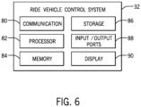
FIG. 6 is a block diagram of an embodiment of a ride vehicle control system of a ride vehicle ofFIG. 1 , in accordance with an aspect of the present disclosure; -
FIG. 7 is a front perspective view of an embodiment of the ride system including the ride vehicles ofFIG. 1 , in accordance with an aspect of the present disclosure; -
FIG. 8 is a rear view of an embodiment of the ride system including the ride vehicles ofFIG. 1 , in accordance with an aspect of the present disclosure; -
FIG. 9 is a flowchart of a method suitable for controlling the ride system ofFIG. 1 based on a rider input, in accordance with an aspect of the present disclosure; -
FIG. 10 is a rear view of an embodiment of the ride system including the ride vehicles ofFIG. 1 and a display system positioned proximate to the ride vehicles, in accordance with an aspect of the present disclosure; -
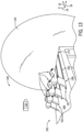
FIG. 11 is a perspective view of an embodiment of a ride system including a ride station and ride vehicles positioned within the ride station, in accordance with an aspect of the present disclosure; -
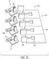
FIG. 12 is a perspective view of an embodiment of the ride system including the ride station ofFIG. 11 and the ride vehicles positioned proximate to the ride station, in accordance with an aspect of the present disclosure; -
FIG. 13 is a rear perspective view of an embodiment of a ride system including ride vehicles, in accordance with an aspect of the present disclosure; -
FIG. 14 is a rear perspective view of an embodiment of the ride system including the ride vehicles ofFIG. 13 , in accordance with an aspect of the present disclosure; -
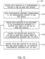
FIG. 15 is a flowchart of a method suitable for controlling the ride system ofFIG. 13 , in accordance with an aspect of the present disclosure; -
FIG. 16 is a perspective view of an embodiment of a ride system including a ride track and a ride vehicle positioned on the ride track, in accordance with an aspect of the present disclosure; and -
FIG. 17 is a flowchart of a method suitable for controlling the ride system ofFIG. 16 , in accordance with an aspect of the present disclosure. - One or more specific embodiments will be described below. In an effort to provide a concise description of these embodiments, not all features of an actual implementation are described in the specification. It should be appreciated that in the development of any such actual implementation, as in any engineering or design project, numerous implementation-specific decisions must be made to achieve the developers' specific goals, such as compliance with system-related and business-related constraints, which may vary from one implementation to another. Moreover, it should be appreciated that such a development effort might be complex and time consuming, but would nevertheless be a routine undertaking of design, fabrication, and manufacture for those of ordinary skill having the benefit of this disclosure.
- When introducing elements of various embodiments of the present disclosure, the articles "a," "an," and "the" are intended to mean that there are one or more of the elements. The terms "comprising," "including," and "having" are intended to be inclusive and mean that there may be additional elements other than the listed elements. Additionally, it should be understood that references to "one embodiment" or "an embodiment" of the present disclosure are not intended to be interpreted as excluding the existence of additional embodiments that also incorporate the recited features.
- Certain ride systems include ride vehicles that may carry riders (e.g., users) within ride areas of the ride systems. Embodiments of the present disclosure are directed to ride vehicles that may move within a ride area of a ride system based on a choreographed routine. For example, the ride system may include multiple ride vehicles that may carry riders within the ride area to entertain and/or transport the riders. Movement of the ride vehicles may be choreographed along ride paths and/or with respect to one another and other portions of the ride system. Additionally, the ride vehicles may move in certain directions relative to a ride area of the ride system, and/or may include rider supports that may carry the riders and move relative to the ride area of the ride system and/or other portions of the ride vehicles. For example, the ride vehicles may include mechanisms and portions (e.g., the rider supports) that may move vertically with respect to a surface of the ride area and/or with respect to a base of the ride vehicle, horizontally in various directions (e.g., may move in any planar direction, may spin, may turn, and so forth), and that may roll (e.g., lean and/or move angularly with respect to the surface of the ride area and/or with respect to the base of the ride vehicle).
- In certain embodiments, the ride system and/or the ride vehicles may include a control system that controls movement of the ride vehicles within the ride area. For example, based on a position of a ride vehicle with respect to a ride path (e.g., based on an actual position of the ride vehicle relative to an intended position of the ride vehicle along the ride path), the control system may adjust a trajectory or traveled course of the ride vehicle. In certain embodiments, as the ride vehicle travels within the ride area, certain factors may affect the trajectory of the ride vehicle, such as obstacles within the ride area, a weight of the rider on the ride vehicle, a weight of other items disposed on or part of the ride vehicle, obstructions attached to the ride vehicle that may be dragging behind, in front of, or to the side of the ride vehicle, rider inputs (e.g., a rider shifting their weight, a rider turning a steering wheel or adjusting the trajectory of the ride vehicle generally, a rider adjusting a speed of the ride vehicle, etc.). As such, the control system may adjust the trajectory or the traveled course of the ride vehicle to generally follow the ride path and to account for such factors.
- In certain embodiments, the ride vehicles of the ride system may include a selected ride vehicle configured to lead the other ride vehicles. A rider riding the selected ride vehicle may provide an input, such as by shifting their weight, controlling a joystick or other hand controller, pressing a button, or a combination thereof. Based on the rider input, a controller of the selected ride vehicle and/or of the ride system may adjust the trajectory of the selected ride vehicle and/or movement of the rider support of the selected ride vehicle. For example, if the rider of the selected ride vehicle provides an input indicative of pulling the rider support of the selected ride vehicle upwardly and leaning the rider support toward the left, the controller may adjust the movement of the selected ride vehicle from the planned and choreographed ride path to generally move the rider support upwardly and to the left. Additionally, the ride system controller may adjust the movement of some or all of the other ride vehicles and/or the rider supports of the other ride vehicles within the ride system. The adjustments to the movements of the other ride vehicles may generally correspond to the movement of the selected ride vehicle (e.g., may be based on a correlative adjustment/movement of the selected ride vehicle or portions thereof), may mirror the movement of the selected ride vehicle, and/or may be of a varying/different degree relative to the movement of the selected ride vehicle. In certain embodiments, the designation of the selected ride vehicle among the ride vehicles of the ride system may change during operation of the ride system. For example, in a first time period during a ride sequence of the ride system (e.g., a time sequence of operation of the ride system), the selected ride vehicle may be a first ride vehicle, and in a second time period during the ride sequence, the selected ride vehicle may be a second, different ride vehicle. As such, the ride system allows the one or multiple riders of the ride system to at least partially control the ride vehicles during the ride sequence and while the riders ride the ride vehicles. The ride system may dynamically adjust the movement of the ride vehicles based on the rider input.
- In certain embodiments, the ride system may include a display system configured to provide a viewing experience that generally corresponds to the movement of the ride vehicles. For example, the viewing experience may be a cinematic presentation that may be viewed by the riders while the riders ride the ride vehicles, and that may enhance the experience of the riders. The graphics of the cinematic presentation may generally move/change to correspond to the choreographed movement of the ride vehicles. In certain embodiments, the input provided to the selected ride vehicle and/or other ride vehicles may adjust the cinematic presentation. For example, the cinematic presentation may be part of a storyline experienced by the riders, and the input provided at the ride vehicles may alter/adjust the storyline (e.g., may choose a particular storyline from multiple possible storylines). In certain embodiments, the ride system may also include an auditory system configured to provide an auditory experience (e.g., sound effects, music, etc.) that generally corresponds to the choreographed movement of the ride vehicles and/or that may be adjusted based on the input provided at the ride vehicles.
- In certain embodiments, the ride system may include a ride station configured to dock/accommodate the ride vehicles. The ride system may dispatch some or all of the ride vehicles from the ride station during operation. For example, the number of ride vehicles dispatched from the ride station may generally depend on a party size (e.g., one rider, two riders, three riders, four riders, six riders, ten riders, etc.) that is riding, or are about to ride, the ride vehicles of the ride system.
- In certain embodiments, the ride system may include a ride vehicle configured to move along a fixed track and that includes one or multiple rider supports configured to be ridden by multiple riders. For example, each rider support may be coupled to a base of the ride vehicle, and the base may move along the track. Each rider support may move relative to the base and relative to one another as the ride vehicle moves along the track. The movement of each rider support may be planned and/or choreographed based on the position of the ride vehicle along the track. Additionally, the ride vehicle may include a selected rider support configured to receive an input from a rider, and a controller of the ride system may control the movement of the selected rider support and/or other rider supports of the ride vehicle based on the input, such as by adjusting the planned and/or choreographed movement of the rider supports. Accordingly, the embodiments of the ride systems described herein may provide an entertaining and interactive experience for the riders of the ride systems.
- Turning to the drawings,
FIG. 1 is a rear perspective view of an embodiment of aride system 10 includingride vehicles 12. To facilitate discussion, eachride vehicle 12 and certain components of theride vehicles 12 may be described with reference to a vertical axis ordirection 14, a longitudinal axis ordirection 16, and a lateral axis ordirection 18. As illustrated, in certain embodiments, eachride vehicle 12 includes abase 20 and a rider support 22 (e.g., a riding assembly) coupled to thebase 20 via alinkage assembly 24. The base 20 may move theride vehicle 12 along a ride path and/or along asurface 26 of aride area 28 of theride system 10, and therider support 22 may carry a rider (e.g., a user) of theride vehicle 12. For example, the rider may ride theride vehicle 12 for entertainment and/or transportation purposes. In certain embodiments, therider support 22 and/or theride vehicle 12 may include ornamental features that enhance the rider's experience, such as features resembling an animal, a fictional character, an automobile, decorations, and/or other objects. While the illustrated embodiment of theride system 10 includes threeride vehicles 12, certain embodiments of theride system 10 may include more or fewer ride vehicles 12 (e.g. oneride vehicle 12, tworide vehicles 12, fourride vehicles 12, fiveride vehicles 12, eightride vehicles 12, etc.). Additionally, in certain embodiments, theride vehicles 12 may share acommon base 20. For example, thecommon base 20 may be significantly wider than the illustratedbases 20 ofFIG. 1 such that thecommon base 20 may accommodate multiple rider supports 22 andmultiple linkage assemblies 24. - During operation of the
ride system 10, the riders may sit on the rider supports 22 of theride vehicles 12, and theride vehicles 12 may traverse thesurface 26 of theride area 28 of theride system 10 via the respective bases 20. As described in greater detail below, in certain embodiments, eachride vehicle 12 may move along a choreographed ride path within the ride system 10 (e.g., along thesurface 26 of the ride area 28) and/or may include mechanisms that enable theride vehicles 12 and/or the rider supports 22 to move vertically (e.g., generally along the vertical axis 14), to move horizontally (e.g., generally along thelongitudinal axis 16 and/or the lateral axis 18), and to roll while moving along the ride path (e.g., to rotate generally about thelongitudinal axis 16 and/or the lateral axis 18). Additionally, each rider may at least partially control/alter the movement of theride vehicles 12 and/or the rider supports 22. The movement of theride vehicles 12 along the choreographed ride path, in the various directions while moving along the ride path, and the ability of the riders to at least partially control the movements of theride vehicles 12 and/or the rider supports 22 may provide an interactive and entertaining experience for the riders. -
FIG. 2 is a block diagram of an embodiment of theride system 10 ofFIG. 1 including theride vehicle 12. Theride system 10 includes aride control system 30 in communication with a ridevehicle control system 32 of theride vehicle 12. As illustrated, theride control system 30 and the ridevehicle control system 32 are communicatively coupled via a wireless connection 34 (e.g., Wi-Fi, Bluetooth, etc.). In certain embodiments, theride control system 30 and the ridevehicle control system 32 may be communicatively coupled via a wired connection (e.g., Ethernet, universal serial bus (USB), CANbus, ISObus, etc.). - The
ride vehicle 12 includes a rider support movement system 40 (e.g., a riding assembly movement system), a ridevehicle movement system 42, and aroll system 44 communicatively coupled to the ridevehicle control system 32, such that the ridevehicle control system 32 may control the ridersupport movement system 40, the ridevehicle movement system 42, and theroll system 44. In certain embodiments, the ridersupport movement system 40, the ridevehicle movement system 42, and/or theroll system 44 may be directly communicatively coupled to theride control system 30, such that theride control system 30 may control the ridersupport movement system 40, the ridevehicle movement system 42, and/or theroll system 44. - The rider
support movement system 40 may move therider support 22 with respect to thebase 20 and/or along thevertical axis 14 and/or thelongitudinal axis 16. In certain embodiments, the ridevehicle movement system 42 may move theride vehicle 12 along thesurface 26 of theride area 28 of theride system 10 generally along thelongitudinal axis 16 and/or thelateral axis 18. For example, the ridevehicle movement system 42 may move theride vehicle 12 in any planar direction (e.g., along a plane parallel to thesurface 26 of the ride area 28), may turn theride vehicle 12, and may spin theride vehicle 12. Theroll system 44 may roll or angle the ride vehicle 12 (e.g., move theride vehicle 12 generally angularly and/or tilt the ride vehicle 12) and/or therider support 22 relative to thesurface 26 of theride area 28 of theride system 10 and generally about thelongitudinal axis 16. - As such, the ride
vehicle control system 32 may control the ridersupport movement system 40, the ridevehicle movement system 42, and theroll system 44 individually (e.g., separately, independently, and/or differently) as theride vehicle 12 moves within theride system 10 to move the rider seated on therider support 22. By moving the rider as theride vehicle 12 travels along the ride path within theride system 10, theride vehicle 12 may provide an entertaining experience for the rider that simulates movement of an animal, a fictional character, an automobile, and/or other entertaining systems or characters. Each of the ridersupport movement system 40, the ridevehicle movement system 42, and theroll system 44 may be coupled to and/or at least partially integrated with thebase 20 of theride vehicle 12. -
FIG. 3 is a block diagram of an embodiment of theride system 10 ofFIG. 1 including the ridersupport movement system 40 of theride vehicle 12. As described above, the ridersupport movement system 40 may move therider support 22 generally along thevertical axis 14 and/or along thelongitudinal axis 16. Additionally, the ridersupport movement system 40 may move therider support 22 with respect to thebase 20 and/or thesurface 26 of theride area 28 of theride system 10. As illustrated, the ridersupport movement system 40 includes thelinkage assembly 24, asupport actuator 50, a ridersupport position sensor 52, and arider controller 54. Thesupport actuator 50 is configured to actuate to cause thelinkage assembly 24 to move therider support 22 relative to thebase 20 and/or thesurface 26 of theride area 28. For example, thesupport actuator 50 may be a piston, a hydraulic cylinder, a pneumatic cylinder, another suitable actuator, or the like, and may be coupled to thelinkage assembly 24. After actuation by thesupport actuator 50, thelinkages 56 of thelinkage assembly 24 may rotate relative to one another (e.g., via a pivot point at which thelinkages 56 are coupled) to cause therider support 22 to move relative to thebase 20 and/or thesurface 26 of theride area 28. For example, afirst linkage 56 may be coupled to thesupport actuator 50 and to asecond linkage 56. Thesupport actuator 50 may move thefirst linkage 56, which may cause movement of thesecond linkage 56 and therider support 22. In certain embodiments, thelinkage assembly 24 may include additional mechanisms to enable/cause the movement of therider support 22 generally along thevertical axis 14 and/or along thelongitudinal axis 16, such as a pin connecting thelinkages 56, an additional actuator coupled to and/or configured to move both thelinkages 56, and other suitable mechanisms. In certain embodiments, the vertical and/or longitudinal motion caused by the ridersupport movement system 40 may be combined with the movement caused by the ridevehicle movement system 42 and/or the roll movement caused by theroll system 44. In certain embodiments, the ridersupport movement system 40 may include movement mechanisms in addition to or in place of thelinkage assembly 24 and/or thesupport actuator 50 configured to move therider support 22 relative to thebase 20 and/or thesurface 26 of theride area 28. - The rider
support position sensor 52 may output a signal indicative of a vertical and/or longitudinal position of therider support 22 relative to thebase 20 and/or thesurface 26 of theride area 28. For example, the ridersupport position sensor 52 may sense a position of therider support 22 along thevertical axis 14, along thelongitudinal axis 16, relative to thebase 20, and/or relative to thesurface 26 of theride area 28, and may output the signal indicative of the vertical and/or longitudinal position of therider support 22. The ridevehicle control system 32 may receive the signal indicative of the vertical and/or longitudinal position of therider support 22 from the ridersupport position sensor 52. Based on the position of therider support 22, the ridevehicle control system 32 may adjust the vertical and/or longitudinal position of therider support 22 relative to thebase 20 and/or thesurface 26 of theride area 28. For example, the ridevehicle control system 32 may output a signal to thesupport actuator 50 to actuate to cause thelinkage assembly 24 to move therider support 22. In certain embodiments, thesupport actuator 50 may be omitted or may be integral to thelinkage assembly 24, such that the ridevehicle control system 32 may communicate directly with thelinkage assembly 24 to cause thelinkage assembly 24 to move therider support 22. Additionally, theride control system 30 may communicate directly with thelinkage assembly 24, or portions thereof, to control the movement of therider support 22. In certain embodiments, theride control system 30 may control vertical and/or longitudinal movement of therider support 22 of theride vehicle 12 based on respective positions of other rider supports 22 ofother ride vehicles 12. For example, based on anotherrider support 22 of another,separate ride vehicle 12 being at a first position, theride control system 30 may control the movement/position of therider support 22 of theride vehicle 12. As such, theride control system 30 may control the movement/position of therider support 22 of eachride vehicle 12 individually (e.g., independently, separately, and/or differently). - As illustrated, the
rider controller 54 is coupled to therider support 22 and communicatively coupled to the ridevehicle control system 32. Therider controller 54 may be any suitable controller configured to receive an input from the rider indicative of adjustment to the movement and/or position of therider support 22, such as a joystick, a gaming controller, or another type of hand controller. In certain embodiments, therider controller 54 may be integral to therider support 22, such as included in handlebars of the rider support 22 (e.g., the rider may provide an input by moving the handlebars, by pressing button(s) on the handlebars, or turning certain mechanisms of the handlebars), included in a body of the rider support 22 (e.g., the rider may shift their weight to provide an input), or incorporated into therider support 22 in other manners. For example, therider controller 54, or theride vehicle 12 generally, may include sensors configured to detect the rider shifting their weight while positioned on therider support 22, such as inertial sensors, accelerometers, pressure sensors, and/or other sensors configured to detect a shift in weight and/or a shift in weight distribution. As such, therider controller 54 may provide an interactive experience for a rider positioned on therider support 22 by allowing the rider to at least partially control the movement/position of therider support 22 and/or theride vehicle 12. -
FIG. 4 is a block diagram of a side view of an embodiment of theride system 10 ofFIG. 1 including the ridevehicle movement system 42 of theride vehicle 12. As described above, the ridevehicle movement system 42 may move theride vehicle 12 generally along thelongitudinal axis 16 and/or thelateral axis 18 and in any planar direction. The ridevehicle movement system 42 may also turn and/or spin theride vehicle 12 along thesurface 26 of theride area 28 of theride system 10. In certain embodiments, the ridevehicle movement system 42 may turn theride vehicle 12 in a first direction while spinning theride vehicle 12 in a second direction. For example, the ridevehicle movement system 42 may turn theride vehicle 12 toward the left while spinning theride vehicle 12 to the right (e.g., while spinning theride vehicle 12 clockwise if viewed from a top view). - As illustrated, the ride
vehicle movement system 42 includes a ridevehicle movement actuator 60, a ridevehicle movement mechanism 62, and a ridevehicle position sensor 64. The ridevehicle movement actuator 60 may actuate to cause the ridevehicle movement mechanism 62 to move theride vehicle 12. For example, the ridevehicle movement actuator 60 may be a piston, a hydraulic cylinder, a pneumatic cylinder, another suitable actuator, and the like, and may be coupled to the ridevehicle movement mechanism 62. After actuation by the ridevehicle movement actuator 60, the ridevehicle movement mechanism 62 may rotate, turn, or perform any other suitable movement to cause theride vehicle 12 to move along thesurface 26 of theride area 28 of theride system 10. For example, the ridevehicle movement mechanism 62 may be wheels, spheres (e.g., steel or rubber balls), a track system, another suitable movement mechanism, or a combination thereof. In certain embodiments, theride vehicle 12 may include more or fewer ride vehicle movement mechanisms 62 (e.g., two ridevehicle movement mechanisms 62, three ridevehicle movement mechanisms 62, five ridevehicle movement mechanisms 62, etc.) configured to move theride vehicle 12 along thesurface 26 of theride area 28. In certain embodiments, the motion caused by the ridevehicle movement system 42 may be combined with the rider support movement caused by the ridersupport movement system 40. For example, while therider support 22 moves relative to thebase 20 and/or thesurface 26 of theride area 28, the ridevehicle movement system 42 may turn, spin, or otherwise move theride vehicle 12 along thesurface 26 of theride area 28 of theride system 10. - The ride
vehicle position sensor 64 may output a signal indicative of a position of theride vehicle 12 within theride system 10. For example, the ridevehicle position sensor 64 may sense a position of theride vehicle 12 along thelongitudinal axis 16, along thelateral axis 16, relative to anotherride vehicle 12, relative to a ride path, relative to other portions of theride system 10, along thesurface 26 of theride area 28, or the like, and output the signal indicative of the position of theride vehicle 12. The ridevehicle control system 32 may receive the signal indicative of the position of theride vehicle 12 from the ridevehicle position sensor 64. Based on the ride vehicle position of theride vehicle 12, the ridevehicle control system 32 may adjust a trajectory (e.g., a course) of theride vehicle 12 along thesurface 26 of theride area 28 of theride system 10. For example, the ridevehicle control system 32 may output a signal to the ride vehicle movement actuator 60 to actuate and cause the ridevehicle movement mechanism 62 to move theride vehicle 12 along thesurface 26 of theride area 28. In certain embodiments, the ridevehicle movement actuator 60 may be omitted or may be integral to the ridevehicle movement mechanism 62, such that the ridevehicle control system 32 may communicate directly with the ridevehicle movement mechanism 62 to cause the ridevehicle movement mechanism 62 to move theride vehicle 12. Additionally, theride control system 30 may communicate directly with the ridevehicle movement system 42, or portions thereof, to control the movement of theride vehicle 12 along thesurface 26 of theride area 28. Theride control system 30 may control the ridevehicle movement mechanism 62 of eachride vehicle 12 individually (e.g., independently, separately, and/or differently) to control the surface movement of eachride vehicle 12. -
FIG. 5 is a block diagram of a side view of an embodiment of theride system 10 ofFIG. 1 including theroll system 44 of theride vehicle 12. As described above, theroll system 44 may move theride vehicle 12 and/or therider support 22 angularly relative to thesurface 26 of theride area 28 of theride system 10. As illustrated, theroll system 44 includes aroll actuator 70, aroll mechanism 72, and aroll sensor 74. Theroll actuator 70 is configured to actuate to cause theroll mechanism 72 to move theride vehicle 12 and/or therider support 22 generally angularly relative to thesurface 26 of theride area 28. For example, theroll actuator 70 may be a piston, a hydraulic cylinder, a pneumatic cylinder, another suitable actuator, or a combination thereof, and may be coupled to theroll mechanism 72. After actuation by theroll actuator 70, theroll mechanism 72 may rotate, turn, or perform any other suitable movement to cause theride vehicle 12 and/or therider support 22 to move generally angularly relative to thesurface 26 of theride area 28. In certain embodiments, theride vehicle 12 may include additional roll mechanisms 72 (e.g., tworoll mechanisms 72, threeroll mechanisms 72, fiveroll mechanisms 72, etc.). The tilting motion of theride vehicle 12 and/or therider support 22 may simulate therider support 22 leaning into a turn as theride vehicle 12 traverses thesurface 26 of theride area 28, via the ridevehicle movement system 42, or may simulate other movements associated with the movement of theride vehicle 12. - In certain embodiments, the
base 20 may be split into two components, including a first component that remains in contact with thesurface 26 of theride area 28 and a second component that moves relative to the first component and thesurface 26 of theride area 28. The second component may be coupled to thelinkage assembly 24 and therider support 22 such that tilting (e.g., rolling) the second component relative to the first component causes therider support 22 to tilt (e.g., roll) relative to thesurface 26 of theride area 28. For example, theroll actuator 70 and/or theroll mechanism 72 may be coupled to the first component and/or the second component of thebase 20, and actuation of theroll actuator 70 may cause theroll mechanism 72 to tilt the second component and therider support 22 relative to the first component of thebase 20 and thesurface 26 of theride area 28. - The
roll sensor 74 may output a signal indicative of an angular position of theride vehicle 12 and/or therider support 22 relative to thebase 20 and/or thesurface 26 of theride area 28. For example, theroll sensor 74 may sense an angular position of theride vehicle 12 and/or therider support 22 about thelateral axis 16 and/or thelongitudinal axis 18 and may output the signal indicative of the angular position of theride vehicle 12 and/or therider support 22. The ridevehicle control system 32 may receive the signal indicative of the angular position of theride vehicle 12 and/or therider support 22 from theroll sensor 74. Based on the angular position of theride vehicle 12 and/or therider support 22, the ridevehicle control system 32 may adjust the angular position of therider support 22 relative to thebase 20 and/or of theride vehicle 12 generally. For example, the ridevehicle control system 32 may output a signal to theroll actuator 70 to actuate to cause theroll mechanism 72 to move therider support 22 generally angularly (e.g., to tilt/lean the rider support 22). In certain embodiments, theroll actuator 70 may be omitted or may be integral to theroll mechanism 72 such that the ridevehicle control system 32 may communicate directly with theroll mechanism 72 to cause theroll mechanism 72 to move theride vehicle 12 and/or therider support 22. Additionally, theride control system 30 may communicate directly with theroll system 44, or portions thereof, to control the angular movement (e.g., tilting) of theride vehicle 12 and/or therider support 22. - Further, the roll movement caused by the
roll system 44 may be combined with the movement caused by the ridersupport movement system 40 and/or the movement caused by the ridevehicle movement system 42. For example, while therider support 22 is leaning to the left or right (e.g., the roll movement caused by the roll system 44), the ridersupport movement system 40 may move therider support 22 generally relative to thebase 20 and/or thesurface 26 of theride area 28, and/or the ridevehicle movement system 42 may turn, spin, or otherwise move theride vehicle 12 along thesurface 26 of theride area 28 of theride system 10. Theride control system 30 may control theroll system 44 of eachride vehicle 12 individually (e.g., independently, separately, and/or differently) to control the roll movement of eachride vehicle 12. -
FIG. 6 is a block diagram of an embodiment of example components of the ridevehicle control system 32 of theride vehicle 12 ofFIG. 1 . For example, in certain embodiments, the ridevehicle control system 32 may include acommunication component 80, aprocessor 82, amemory 84, astorage 86, input/output (I/O)ports 88, adisplay 90, and the like. Thecommunication component 80 may be a wireless or wired communication component that may facilitate communication between the ridevehicle control system 32 and theride control system 30, the ridersupport movement system 40, the ridevehicle movement system 42, and theroll system 44. For example, thecommunication component 80 may provide for thewireless connection 34 ofFIGS. 2-5 and/or a wired connection. - The
processor 82 may be any suitable type of computer processor or microprocessor capable of executing computer-executable code. Theprocessor 82 may also include multiple processors that may perform the operations described below. Thememory 84 and thestorage 86 may be any suitable articles of manufacture that can serve as media to store processor-executable code, instructions, data, or the like. These articles of manufacture may represent computer-readable media (e.g., any suitable form of memory or storage) that may store the processor-executable code used by theprocessor 82 to perform the presently disclosed techniques. Thememory 84 and thestorage 86 may also be used to store the data and various other software applications. Thememory 84 and thestorage 86 may represent non-transitory computer-readable media (e.g., any suitable form of memory or storage) that may store the processor-executable code (e.g., instructions) used by theprocessor 82 to perform various techniques described herein. It should be noted that non-transitory merely indicates that the media is tangible and not a signal. - The I/
O ports 88 may be interfaces that may couple to other peripheral components such as input devices (e.g., keyboard, mouse), sensors, and input/output (I/O) modules. Thedisplay 90 may operate to depict visualizations associated with software or executable code being processed by theprocessor 82. In one embodiment, thedisplay 90 may be a touch display capable of receiving inputs from a rider of theride vehicle 12. Thedisplay 90 may be any suitable type of display, such as a liquid crystal display (LCD), plasma display, or an organic light emitting diode (OLED) display, for example. - It should be noted that the components described above with regard to the ride
vehicle control system 32 are exemplary components, and the ridevehicle control system 32 may include additional or fewer components as shown. Additionally, theride control system 30 may include components similar to those illustrated for the ridevehicle control system 32, such as a communication component, a processor, a memory, a storage, input/output (I/O) ports, and/or a display. -
FIG. 7 is a front perspective view of an embodiment of theride system 10 including theride vehicles 12 ofFIG. 1 . As illustrated, therider support 22 of eachride vehicle 12 is positioned differently with respect to one another along thevertical axis 14 and along thelongitudinal axis 16. The embodiment ofFIG. 7 illustrates the relative positions of theride vehicles 12 and the rider supports 22 of theride vehicles 12 during a ride sequence of theride system 10. For example, aride vehicle 12A includes arider support 22A positioned farther forward along thelongitudinal axis 16 relative to the rider supports 22B and 22C of theride vehicles support movement system 40 of theride vehicle 12A is actuated in the illustrated embodiment to move therider support 22A generally forward relative to thebase 20. - The relative position of the
rider support 22A may be based on a predetermined/choreographed routine of theride vehicles 12 and/or based on a rider input. For example, theride vehicle 12A may be a selected ride vehicle of theride vehicles ride system 10. A rider positioned on therider support 22A may provide an input, such as to a rider controller coupled to and/or part of therider support 22A, indicative of an adjustment to the movement/position of therider support 22A. The adjustment may include therider support 22A moving generally forward relative to the choreographed routine. Additionally, as illustrated, therider support 22B of theride vehicle 12B is positioned slightly forward along thelongitudinal axis 16 relative to therider support 22C of theride vehicle 12C. This positioning of therider support 22B may be based on the rider input provided at theride vehicle 12A and/or based on the choreographed routine. As such, the rider of the selected ride vehicle (e.g., theride vehicle 12A) may provide an input that dynamically adjusts the movement and positioning of the group ofride vehicles 12 within the ride system 10 (e.g., a correlative adjustment). In certain embodiments, the selected ride vehicle may be a different ride vehicle 12 (e.g., theride vehicle ride vehicles ride system 10. -
FIG. 8 is a rear view of an embodiment of theride system 10 including theride vehicles 12 ofFIG. 1 . As illustrated, eachrider support 22 of theride vehicles 12 is positioned differently with respect to one another along thevertical axis 14, along thelongitudinal axis 16, and along thelateral axis 18. The embodiment ofFIG. 8 illustrates the relative positions of theride vehicles 12 and the rider supports 22 of theride vehicles 12 during a ride sequence of theride system 10. For example, theride vehicle 12A includes therider support 22A positioned generally higher along thevertical axis 14 relative to the rider supports 22B and 22C of theride vehicles rider support 22A may be based on a predetermined/choreographed routine of theride vehicles 12 and/or based on a rider input. For example, the position of therider support 22A may be a result of the rider of theride vehicle 12A pulling upwardly on therider support 22A. - As illustrated, each
base 20 of theride vehicles 12 includes anupper base component 94 and alower base component 96 coupled to one another. Eachupper base component 94 is coupled to thelinkage assembly 24 and therider support 22 of therespective ride vehicles 12. Additionally, eachupper base component 94 is angularly offset relative to the respectivelower base component 96 such that each base 20 provides an amount of roll/tilt for the respective ride vehicles. For example, theroll mechanism 72 of theroll system 44 of eachride vehicle 12 may include theupper base component 94 and/or thelower base component 96. Theroll actuator 70 may be coupled to theupper base component 94 and/or thelower base component 96 and configured to actuate to roll/tilt theupper base component 94 and therider support 22 relative to thelower base component 96 and thesurface 26 of theride area 28. In the illustrated embodiment, theroll actuator 70 of eachride vehicle 12 is actuated to cause the respectiveupper base components 94 and the rider supports 22 to tilt to the right (e.g., generally downwardly along thevertical axis 14 and to the right along the lateral axis 18). -
FIG. 9 is a flowchart of amethod 100 suitable for controlling theride system 10 ofFIG. 1 based on a choreographed routine and/or a rider input. Although the following description of themethod 100 is detailed as being performed by theride control system 30, it should be noted that any suitable computing system may perform themethod 100 described below. Moreover, it should be noted that, although themethod 100 is described below in a particular order, themethod 100 may be performed in any suitable order. - At
block 102, theride control system 30 receives an input indicative of a choreographed routine of one ormore ride vehicles 12. For example, the choreographed routine may include a ride path for each ride vehicle 12 (e.g., choreographed movement of eachride vehicle 12 along thesurface 26 of the ride area 28) and choreographed movement of eachride vehicle 12 along the respective ride path (e.g., choreographed rider support movement along thevertical axis 14 and/or along thelongitudinal axis 16 and choreographed roll movement about the longitudinal axis 16). In certain embodiments, theride system 10 may include multiple and/or different choreographed routines of theride vehicles 12. For example, a first choreographed routine may include a first set of ride paths and choreographed movements of theride vehicles 12 along the ride paths, and a second choreographed routine may include a second set of ride paths and choreographed movements of theride vehicles 12 along the ride paths that is partially or wholly different from the first choreographed routine. The multiple/different choreographed routines allow theride system 10 to provide varying experiences for the riders of theride vehicles 12 and enhance a re-ridability appeal of theride system 10. Additionally, some choreographed routines may not include all of theride vehicles 12 of theride system 10. For example, as described in greater detail below, theride system 10 may be configured to dispatch only a subset of theride vehicles 12 based on the choreographed routine, among other factors. - In certain embodiments, each ride path and the choreographed movements of each
ride vehicle 12 may be generally similar and may generally follow a similar pattern. For example, the choreographed movements of theride vehicles 12 may include theride vehicles 12 maintaining a "V" formation while moving along theride system 10. In other embodiments, the ride paths and/or the choreographed movements of some or all of theride vehicles 12 may be different from one another. - At
block 104, theride control system 30 sends the ride path and the choreographed movement of eachride vehicle 12 that corresponds to the choreographed routine of theride system 10 to eachride vehicle 12. The respective ridevehicle control system 32 of eachride vehicle 12 may receive the ride path and the choreographed movement and may control theride vehicle 12 based on the ride path and the choreographed movement. For example, the ridevehicle control system 32 may control the ridersupport movement system 40, the ridevehicle movement system 42, and theroll system 44 to follow the respective ride path and the respective choreographed movements. In certain embodiments, theride control system 30 may be directly communicatively coupled to and configured to control the ridersupport movement system 40, the ridevehicle movement system 42, and/or theroll system 44 of eachride vehicle 12 to follow the respective ride paths and the respective choreographed movements. - At
block 106, theride control system 30 receives an input indicative of an adjustment to the ride path and/or the choreographed movement of a selectedride vehicle 12. For example, the input may be received from therider controller 54 of the selectedride vehicle 12 and/or via the ridevehicle control system 32 of the ride vehicle 12 (e.g., the ridevehicle control system 32 may receive the input from therider controller 54 and may provide the input to the ride control system 30). As described herein, the input to therider controller 54 may be a rider of the selectedride vehicle 12 shifting their weight while positioned on therider support 22 of the selectedride vehicle 12 and/or an input provided by the rider to a hand controller or another control device configured to be controlled by the rider. - At
block 108, theride control system 30 may control the selectedride vehicle 12 based on the ride path, the choreographed movement, and the input indicative of the adjustment to the ride path and/or the choreographed movement of a selectedride vehicle 12. For example, the input received from therider controller 54 may cause theride control system 30 to dynamically adjust the rider support movement along thevertical axis 14 and/or along thelongitudinal axis 16, the roll movement of theride vehicle 12 and/or therider support 22 about thelongitudinal axis 16, and/or the movement along thesurface 26 of theride area 28 of theride system 10. The adjustment to the movement may include an adjustment to the choreographed ride path of the selectedride vehicle 12. - At
block 110, theride control system 30 may controlother ride vehicles 12 of the ride system 10 (e.g., besides the selected ride vehicle 12) based on the respective ride paths of eachride vehicle 12, respective choreographed movements of eachride vehicle 12, and the input indicative of the adjustment to the ride path and/or the choreographed movement of a selectedride vehicle 12. As described above, the respective ride path and choreographed movement of eachride vehicle 12 along the respective ride path may generally follow a similar pattern, or the ride paths and/or choreographed movements of someride vehicles 12 may be different. As theride vehicles 12 move along thesurface 26 of theride area 28, such as in the "V" formation described above, theride control system 30 may receive the input from therider controller 54 and may adjust the ride path and/or the choreographed movement of both the selectedride vehicle 12 and theother ride vehicles 12 of theride system 10. The adjustments to theother ride vehicles 12 may be of varying degrees relative to the adjustments to the selectedride vehicle 12. For example, if the input at therider controller 54 causes theride control system 30 to move the selectedride vehicle 12 upwardly (e.g., to simulate the rider of the selectedride vehicle 12 pulling the selectedride vehicle 12 upwardly), theride control system 30 may also move theother ride vehicles 12 upwardly and/or by varying amounts. Theother ride vehicle 12 immediately next to the selectedride vehicle 12 may move upwardly more so relative to theother ride vehicles 12 of theride system 10. As such, theride system 10, via theride control system 30, may simulate theother ride vehicles 12 moving based on the input provided at the selectedride vehicle 12 such that the rider of the selectedride vehicle 12 may appear to be a leader of the riders within theride system 10. -
FIG. 10 is a rear view of an embodiment of theride system 10 including theride vehicles 12 ofFIG. 1 positioned proximate to adisplay system 118 of theride system 10 including ascreen 120 and aprojector 122. Thedisplay system 118 is configured to provide a cinematic presentation for viewing by the riders positioned on the ride vehicles 12 (e.g., positioned on the rider supports 22 of the ride vehicles 12). For example, thescreen 120 of thedisplay system 118 may be a video board configured to provide the cinematic presentation, and/or theprojector 122 may be configured to project the cinematic presentation onto thescreen 120 for viewing by the riders on theride vehicles 12. In certain embodiments, theprojector 122 may be omitted from thedisplay system 118. - The
ride control system 30 may control/coordinate the movements of theride vehicles 12 and/or the rider supports 22 based on the cinematic presentation. For example, theride control system 30 may control the ridersupport movement system 40, the ridevehicle movement system 42, and theroll system 44 of eachride vehicle 12 based on the cinematic presentation to simulate movement of theride vehicles 12 within a scene of the cinematic presentation. In certain embodiments, theride vehicles 12 may remain in generally the same positions on thesurface 26 of theride area 28 during the cinematic presentation, and the rider supports 22 may move vertically, longitudinally, and angularly relative to thesurface 26 of theride area 28 during the cinematic presentation. - In certain embodiments, the
ride control system 30 may control/coordinate the movements of theride vehicles 12 and/or the rider supports 22 based on the input provided at the selectedride vehicle 12. For example, the cinematic presentation may include multiple optional story lines that may be selected based on the input received from therider controller 54. Each option/storyline may correspond to a specific and/or different choreographed routine or a different portion of the choreographed routine of the rider supports 22. As such, theride system 10, via thedisplay system 118, may provide an interactive experience for the riders of theride vehicles 12 that allows the riders to control the storyline of theride system 10 and the choreographed movement of the rider supports 22. In certain embodiments, theride control system 30 may instruct thedisplay system 118 to provide the cinematic presentation (e.g., may instruct thescreen 120 to provide the cinematic presentation and/or may instruct theprojector 122 to project the cinematic presentation onto the screen 120). -
FIG. 11 is a perspective view of an embodiment of theride system 10 ofFIG. 1 including aride station 130 and theride vehicles 12 positioned within theride station 130. As illustrated, theride station 130 includes abay 132 for eachride vehicle 12. For example, eachbay 132 may be configured to receive and/or accommodate arespective ride vehicle 12 while theride vehicle 12 is not in aride area 28 of theride system 10. Additionally, while positioned within thebays 132, theride vehicles 12 may be configured to receive riders. For example, the riders may travel along aplatform 136 of theride station 130 and move onto the rider supports 22 of theride vehicles 12. Theride vehicles 12 may exit thebays 132 and move into theride area 28 to perform the choreographed routine (e.g., to travel along respective choreographed ride paths and to perform choreographed movements while traveling along the ride paths). For example, after the riders move onto theride vehicles 12,gates 138 coupled to theplatform 136 and disposed proximate to thebays 132 may open to allow theride vehicles 12 to exit thebays 132. As illustrated, thegates 138 are in an open position such that theride vehicles 12 may exit thebays 132. -
FIG. 12 is a perspective view of an embodiment of theride system 10 including theride station 130 ofFIG. 11 and theride vehicles 12 positioned within theride area 28 proximate to theride station 130. As illustrated, theride vehicles 12 have moved from the positions within the bays 132 (e.g., the positions illustrated inFIG. 11 ) to positions within theride area 28. The embodiment ofFIG. 12 may be a beginning portion of the choreographed routine of theride system 10 in which theride vehicles 12 have exited thebays 132 and turned (e.g., via the ride vehicle movement systems 42) such that theride vehicles 12 are generally facing away from theride station 130. - As illustrated, all four of the
ride vehicles 12 have departed from theride station 130 and moved into theride area 28. In certain embodiments, only a subset of the ride vehicles 12 (e.g., oneride vehicle 12, tworide vehicles 12, or three ride vehicles in the illustrated embodiment) may depart from theride station 130. The quantity ofride vehicles 12 may depend on a party size of the riders about to ride or the party size of the riders positioned on theride vehicles 12, the choreographed routine of the ride vehicles 12 (e.g., as described above, some choreographed routines may not include all theride vehicles 12 of the ride system 10), and other factors. In certain embodiments, theride vehicles 12 may transition from the position within thebays 132 ofFIG. 11 and/or the position in theride area 28 ofFIG. 12 to the position in front of thescreen 120 ofFIG. 10 . As such, theride system 10 may dispatch some or all of theride vehicles 12 to provide a customized/personalized experience for the riders of theride vehicles 12. -
FIG. 13 is a rear perspective view of an embodiment of aride system 160 includingride vehicles 162 and aplatform 164. Theride vehicles 162 and/or theride system 160 generally may include systems configured to move theride vehicles 162 along thevertical axis 14, thelongitudinal axis 16, and/or thelateral axis 18. For example, as described below in reference toFIG. 14 , theride vehicles 162 may be configured to move withinslots 166 of theplatform 164 via a ride vehicle movement system (e.g., from arear portion 168 toward a front portion 170). Additionally, eachride vehicle 162 may include a rider support movement system configured to move arider support 172 of theride vehicle 162 generally along thevertical axis 14, along thelongitudinal axis 16, and/or relative to theplatform 164. In certain embodiments, eachride vehicle 162 may include a roll system configured to roll/tilt therider support 172 about thelongitudinal axis 16 and relative to theplatform 164. Eachrider support 172 is configured to carry a rider, and theride system 160 is configured to provide an entertaining experience for each rider. For example, as theride vehicles 162 move within theslots 166, the riders may also move while positioned on the rider supports 172. As illustrated, theride system 160 includes fourride vehicles 162. In certain embodiments, theride system 160 may include more or fewer ride vehicles 162 (e.g., oneride vehicle 162, tworide vehicles 162, threeride vehicles 162, fiveride vehicles 162, eightride vehicles 162, etc.). - Additionally, the
ride system 160 may include theride control system 30, and eachride vehicle 162 may include the ridevehicle control system 32 described above with respect to theride system 10. Theride control system 30 may control the movements of the ride vehicles 162 (e.g., via communication with the ridevehicle control system 32 of each ride vehicle 162) based on a choreographed routine. For example, theride control system 30 may control the rider support movement system, the ride vehicle movement system, and/or the roll system of eachride vehicle 162 to cause eachride vehicle 162 to move according to the choreographed routine. As described in greater detail below, theride control system 30 may also control theride vehicles 162 based on an input received from a selectedride vehicle 162 of theride vehicles 162. -
FIG. 14 is a rear perspective view of an embodiment of theride system 160 including theride vehicles 162 ofFIG. 13 . As illustrated, theride vehicles 162 are positioned at thefront portion 170 of theslots 166. Eachride vehicle 162 includes arespective rider support 172, alinkage 180 coupled to therider support 172, and a base 182 coupled to thelinkage 180. While theride vehicles 162 are positioned at thefront portions 170 of theslots 166, the rider supports 172 and a portion of eachlinkage 180 extend beyond theplatform 164. This extension beyond theplatform 164 may provide the appearance to each rider positioned on the rider supports 172 that the rider supports 172 are flying and/or may provide an entertaining experience. - As illustrated, each
ride vehicle 162 includes a ridersupport movement system 190 and a ridevehicle movement system 192. The ridersupport movement system 190 of eachride vehicle 162 is configured to move therider support 172 relative to theplatform 164 and along thevertical axis 14 and along the longitudinal axis 16 (e.g., generally about the lateral axis 18). The ridersupport movement system 190 may include thelinkage 180, thebase 182, or portions thereof. For example, the ridersupport movement system 190 may include a support actuator coupled to thelinkage 180 and/or the base 182 that is configured to actuate to move thelinkage 180 relative to thebase 182 and theplatform 164. - The ride
vehicle movement system 192 includes atrack 194 positioned below theplatform 164 and that extends generally along thelongitudinal axis 16. Thetrack 194 is coupled to the base 182 such that the base 182 may move within thetrack 194 and along thelongitudinal axis 16. For example, the ridevehicle movement system 192 may include a base movement actuator configured to actuate to move thebase 182 within thetrack 194 and relative to theplatform 164. As the base 182 moves along thetrack 194, thelinkage 180 also moves within theslot 166. - In certain embodiments, the
ride system 160 and/or eachride vehicle 162 may include a roll system configured to move therider support 172 angularly relative to thebase 182 and about thelongitudinal axis 16. For example, the roll system may include a roll actuator configured to actuate to move therider support 172 relative to thebase 182 and theplatform 164. - Each of the rider
support movement system 190, the ridevehicle movement system 192, and the roll system may be controlled by theride control system 30 and/or the ridevehicle control system 32 of eachride vehicle 162 based on the choreographed routine. For example, the choreographed routine may include specific movements of eachrider support 172 along thevertical axis 14, thelongitudinal axis 16, and thelateral axis 18 that are performed by the respective ridersupport movement system 190, ridevehicle movement system 192, and roll system of eachride vehicle 162. The choreographed movement of eachrider support 172 may be different, or the choreographed movements of some or all of the rider supports 172 may generally be the same. In the illustrated embodiment, eachrider support 172 is positioned differently along thevertical axis 14. For example, the embodiment ofFIG. 14 illustrates theride vehicles 162 during a ride sequence of theride system 160 that includes each rider support at varying positions along thevertical axis 14. In certain embodiments, as described in greater detail below, theride control system 30 may control theride vehicles 162 based on an input provided to a rider controller of a selectedride vehicle 162 in addition to or in place of the choreographed movements of the choreographed routine. - The
ride system 160 includes thedisplay system 118. Thedisplay system 118 is configured to provide a cinematic presentation for viewing by the riders positioned on the ride vehicles 162 (e.g., positioned on the rider supports 172 of the ride vehicles 162). Theride control system 30 may control/coordinate the movements of theride vehicles 162 and/or the rider supports 172 based on the cinematic presentation. For example, theride control system 30 may control the ridersupport movement system 190, the ridevehicle movement system 192, and the roll system of eachride vehicle 162 based on the cinematic presentation to simulate movement of theride vehicles 162 within a scene of the cinematic presentation. In certain embodiments, theride control system 30 may instruct thedisplay system 118 to provide the cinematic presentation. -
FIG. 15 is a flowchart of amethod 200 suitable for controlling theride system 160 ofFIG. 13 based on a choreographed routine and/or a rider input. Although the following description of themethod 200 is detailed as being performed by theride control system 30, it should be noted that any suitable computing system may perform themethod 200 described below. Moreover, it should be noted that although themethod 200 is described below in a particular order, themethod 200 may be performed in any suitable order. - At
block 202, theride control system 30 receives an input indicative of a choreographed routine of one ormore ride vehicles 162. For example, the choreographed routine may include choreographed rider support movement of eachrider support 172 along thevertical axis 14 and/or along thelongitudinal axis 16 and choreographed roll movement about thelongitudinal axis 16. In certain embodiments, theride system 160 may include multiple and/or different choreographed routines of theride vehicles 162. For example, a first choreographed routine may include a first set of choreographed movements of theride vehicles 162, and a second choreographed routine may include a second set of choreographed movements of theride vehicles 162 that is partially or wholly different from the first choreographed routine. The multiple/different choreographed routines allow theride system 160 to provide varying experiences for the riders of theride vehicles 162 and enhance a re-ridability appeal of theride system 160. Additionally, some choreographed routines may not include all of theride vehicles 162 of theride system 160. For example, theride system 160 may be configured to dispatch only a subset of theride vehicles 162 based on the choreographed routine, among other factors (e.g., such as party size). - At
block 204, theride control system 30 sends the choreographed movement of eachride vehicle 162 that corresponds to the choreographed routine of theride system 160 to eachride vehicle 162. The respective ridevehicle control system 32 of eachride vehicle 162 may receive the choreographed movement and may control theride vehicle 162 based on the choreographed movement. For example, the ridevehicle control system 32 may control the ridersupport movement system 190, the ridevehicle movement system 192, and the roll system to follow the respective choreographed movements. In certain embodiments, theride control system 30 may be directly communicatively coupled to and configured to control the ridersupport movement system 190, the ridevehicle movement system 192, and/or the roll system of eachride vehicle 162 to follow the respective choreographed movements. - At
block 206, theride control system 30 receives an input indicative of an adjustment to the ride path and/or the choreographed movement of a selectedride vehicle 162. For example, some or all of theride vehicles 162 may include therider controller 54, and oneride vehicle 162 may be designated as the selectedride vehicle 162 in a given time period during a ride sequence of theride system 160. An input may be received from therider controller 54 of the selectedride vehicle 162 and/or via the ridevehicle control system 32 of the ride vehicle 162 (e.g., the ridevehicle control system 32 may receive the input from therider controller 54 and may provide the input to the ride control system 30). As described herein, the input to therider controller 54 may be a rider of the selectedride vehicle 162 shifting their weight while positioned on therider support 172 of the selectedride vehicle 162, and/or an input provided by the rider to a hand controller or another control device. - At
block 208, theride control system 30 may control the selectedride vehicle 162 based on the choreographed movement and the input indicative of the adjustment to the choreographed movement of a selectedride vehicle 162. For example, the input received from therider controller 54 may cause theride control system 30 to dynamically adjust the rider support movement along thevertical axis 14 and/or along thelongitudinal axis 16, the roll movement of theride vehicle 162 and/or therider support 172 about thelongitudinal axis 16, and/or the movement along thetrack 194 of theride system 160. - At
block 210, theride control system 30 may controlother ride vehicles 162 of the ride system 160 (e.g., besides the selected ride vehicle 162) based on the respective choreographed movements of eachride vehicle 162 and the input indicative of the adjustment to the choreographed movement of the selectedride vehicle 162. As described above, the respective choreographed movement of eachride vehicle 162 may generally follow a similar pattern, or the choreographed movements of someride vehicles 162 may be different. As theride vehicles 162 move within thetracks 194, such as in a "V" formation, theride control system 30 may receive the input from therider controller 54 and may adjust the choreographed movement of both the selectedride vehicle 162 and theother ride vehicles 162 of theride system 160. The adjustments to theother ride vehicles 162 may be of varying degrees relative to the adjustments to the selectedride vehicle 162. For example, if the input at therider controller 54 causes theride control system 30 to move the selectedride vehicle 162 upwardly (e.g., to simulate the rider of the selectedride vehicle 162 pulling the selectedride vehicle 162 upwardly), theride control system 30 may also move theother ride vehicles 162 upwardly and/or by varying amounts. Theother ride vehicle 162 immediately next to the selectedride vehicle 162 may move upwardly more so relative to theother ride vehicles 162 of theride system 160. As such, theride system 160, via theride control system 30, may simulate theother ride vehicles 162 moving based on the input provided at the selectedride vehicle 162 such that the rider of the selectedride vehicle 162 may appear to be a leader of the riders within theride system 160. -
FIG. 16 is a perspective view of an embodiment of aride system 220 including aride track 222 and aride vehicle 224 positioned on theride track 222. As illustrated, theride vehicle 224 includes a base 226 coupled to theride track 222 and rider supports 228 coupled to thebase 226 viarespective linkage assemblies 230. Theride vehicle 224 include systems configured to move theride vehicle 224 along theride track 222 and move the rider supports 228 relative to thebase 226 for the entertainment of riders riding the rider supports 228 of theride vehicle 224. For example, theride vehicle 224 includes a ridevehicle movement system 232 configured to move thebase 226 along theride track 222. The ridevehicle movement system 232 may include a base movement actuator, wheels, gears, and other suitable mechanisms configured to move thebase 226 along theride track 222. The movement and/or speed of theride vehicle 224 along the ride track 222 (e.g., via the base 226) may be based on a choreographed routine of theride system 220. - The
ride vehicle 224 also includes ridersupport movement systems 240 configured to move eachrider support 228 relative to one another, theride track 222, and/or thebase 226. Each ridersupport movement system 240 may include arespective rider support 228, arespective linkage assembly 230, and/or a support actuator. The support actuator may be configured to actuate to cause thelinkage assembly 230 to move therider support 228 relative to thebase 226 and/or theride track 222. After actuation by the support actuator,linkages 242 of thelinkage assembly 230 may rotate relative to one another (e.g., via a pivot point at which thelinkages 242 are coupled) to cause therider support 228 to move relative to thebase 226 and/or theride track 222. For example, afirst linkage 242 may be coupled to the support actuator and to asecond linkage 242. The support actuator may move thefirst linkage 242, which may cause movement of thesecond linkage 242 and therider support 228. In certain embodiments, thelinkage assembly 230 may include additional mechanisms to enable/cause the movement of therider support 228 generally along thevertical axis 14 and/or along thelongitudinal axis 16, such as a pin connecting thelinkages 242, an additional actuator coupled to and/or configured to move both thelinkages 242, and other suitable mechanisms. - The
ride vehicle 224 includes aroll system 250 configured to move theride vehicle 224 angularly relative to the ride track 222 (e.g., to rotate theride vehicle 224 about thelongitudinal axis 16 and the ride track 222). Theroll system 250 may include thebase 226 and a roll actuator configured to move the base 226 angularly relative to theride track 222. For example, the roll actuator may be configured to actuate to cause the base 226 to move angularly relative to theride track 222. In certain embodiments, theride vehicle 224 may includemultiple roll systems 250 with eachroll system 250 configured to move arespective rider support 228 angularly relative to the base 226 (e.g., to rotate about thelongitudinal axis 16 and the base 226). - Additionally, the
ride system 220 may include theride control system 30, and/or eachrider support 228 may include the ridevehicle control system 32 described above with respect to theride system 10. Theride control system 30 may control the movements of the ride vehicle 224 (e.g., via communication with the ridevehicle control systems 32 of each rider support 228) based on a choreographed routine. For example, theride control system 30 may control the ridersupport movement system 240 and the roll system of theride vehicle 224 of eachrider support 228 to cause theride vehicle 224 and eachrider support 228 to move according to the choreographed routine. As described in greater detail below, theride control system 30 may also control theride vehicle 224 and the rider supports 228 based on an input received from a selectedrider support 228 of the rider supports 228. In certain embodiments, theride vehicle 224 may include an independent controller, such as a controller similar to the ridevehicle control system 32, configured to control theride vehicle 224. -
FIG. 17 is a flowchart of amethod 260 suitable for controlling theride system 220 ofFIG. 16 based on a choreographed routine and/or a rider input. Although the following description of themethod 260 is detailed as being performed by theride control system 30, it should be noted that any suitable computing system may perform themethod 260 described below. Moreover, it should be noted that although themethod 260 is described below in a particular order, themethod 260 may be performed in any suitable order. - At
block 262, theride control system 30 receives an input indicative of a choreographed routine of theride vehicle 224 and the rider supports 228. For example, the choreographed routine may include choreographed ride vehicle movement of theride vehicle 224 along theride track 222, choreographed roll movement of theride vehicle 224 about thelongitudinal axis 16, and choreographed rider support movement of eachrider support 228 along thevertical axis 14 and/or along thelongitudinal axis 16. In certain embodiments, theride system 220 may include multiple and/or different choreographed routines of the rider supports 228. For example, a first choreographed routine may include a first set of choreographed movements of the rider supports 228, and a second choreographed routine may include a second set of choreographed movements of the rider supports 228 that is partially or wholly different from the first choreographed routine. The multiple/different choreographed routines allow theride system 220 to provide varying experiences for the riders of the rider supports 228 and may enhance a re-ridability appeal of theride system 220. - At
block 264, theride control system 30 sends the choreographed movement of eachrider support 228 that corresponds to the choreographed routine of theride system 220 to eachrider support 228. The respective ridevehicle control system 32 of eachrider support 228 may receive the choreographed movement and may control therider support 228 based on the choreographed movement. For example, the ridevehicle control system 32 of eachrider support 228 may control the respective ridersupport movement system 240. In certain embodiments, theride control system 30 may be directly communicatively coupled to and configured to control the ridersupport movement system 240 to follow the respective choreographed movements. Additionally, theride control system 30 may control the ridevehicle movement system 232 and/or theroll system 250 of theride vehicle 224 based on the choreographed routine. - At
block 266, theride control system 30 receives an input indicative of an adjustment to the choreographed movement of a selectedrider support 228. For example, some or all of the rider supports 228 may include therider controller 54, and onerider support 228 may be designated as the selectedrider support 228 in a given time period during a ride sequence of theride system 220. An input may be received from therider controller 54 of the selectedrider support 228 and/or via the ridevehicle control system 32 of the selected rider support 228 (e.g., the ridevehicle control system 32 may receive the input from therider controller 54 and may provide the input to the ride control system 30). As described herein, the input to therider controller 54 may be a rider of the selectedrider support 228 shifting their weight while positioned on the selectedrider support 228 and/or an input provided by the rider to a hand controller or another control device configured to be controlled by the rider. - At
block 268, theride control system 30 may control the selectedrider support 228 based on the choreographed movement and the input indicative of the adjustment to the choreographed movement of a selectedrider support 228. For example, the input received from therider controller 54 may cause theride control system 30 to dynamically adjust the rider support movement along thevertical axis 14 and/or along thelongitudinal axis 16. In certain embodiments, theride control system 30 may control the ride vehicle movement and/or the roll movement of the ride vehicle 224 (e.g., via the ridevehicle movement system 232 and/or the roll system 250) based on the choreographed routine and the input indicative of the adjustment to the choreographed movement. For example, the input provided by the rider of the selectedrider support 228 may cause theride control system 30 to adjust the ride vehicle movement and/or the roll movement of theride vehicle 224. - At
block 270, theride control system 30 may control other rider supports 228 of the ride system 220 (e.g., besides the selected rider support 228) based on the respective choreographed movements of eachrider support 228 and the input indicative of the adjustment to the choreographed movement of the selectedrider support 228. As described above, the respective choreographed movement of eachrider support 228 may generally follow a similar pattern, or the choreographed movements of some rider supports 228 may be different. As the rider supports 228 move along the ride track 222 (e.g., via the base 226), such as in a "V" formation, theride control system 30 may receive the input from therider controller 54 and may adjust the choreographed movement of both the selectedrider support 228 and the other rider supports 228 of theride vehicle 224. The adjustments to the other rider supports 228 may be of varying degrees relative to the adjustments to the selectedrider support 228. For example, if the input at therider controller 54 causes theride control system 30 to move the selectedrider support 228 upwardly (e.g., to simulate the rider of the selectedrider support 228 pulling the selectedrider support 228 upwardly), theride control system 30 may also move the other rider supports 228 upwardly and/or by varying amounts. Theother rider support 228 immediately next to the selectedrider support 228 may move upwardly more so relative to the other rider supports 228 of theride vehicle 224. As such, theride system 220, via theride control system 30, may simulate the other rider supports 228 moving based on the input provided at the selectedrider support 228 such that the rider of the selectedrider support 228 may appear to be a leader of the riders within theride system 220. - As set forth above, embodiments of the ride systems of the present disclosure may provide one or more technical effects useful in enhancing riders' experiences while riding ride vehicles and rider supports of the ride vehicles within the ride systems. For example, some ride systems may include multiple ride vehicles that may carry riders within the ride area to entertain and/or transport the riders. Movement of the ride vehicles may be choreographed along ride paths and/or with respect to one another and other portions of the ride system. Additionally, the ride vehicles may move in certain directions relative to a surface of a ride area of the ride system, and/or may include rider supports that may carry the riders and move relative to the surface of the ride area of the ride system and/or other portions of the ride vehicles. For example, the ride vehicles may include mechanisms and portions (e.g., the rider supports) that may move vertically with respect to a surface of the ride area and a base of the ride vehicle, horizontally in various directions (e.g., may move in any planar direction, may spin, and may turn), and that may roll (e.g., lean and/or move angularly with respect to the surface of the ride area). In certain embodiments, the ride systems and/or the ride vehicles may include a control system that controls movement of the ride vehicles within the ride area. For example, based on a position of a ride vehicle with respect to a ride path (e.g., based on an actual position of the ride vehicle relative to an intended position of the ride vehicle along the ride path), the control system may adjust a trajectory or traveled course of the ride vehicle.
- In certain embodiments, the ride vehicles of the ride system may include a selected ride vehicle configured to lead the ride vehicles. A rider riding the selected vehicle may provide an input, such as by shifting their weight, controlling a joystick or other hand controller, pressing a button, or a combination thereof. Based on the rider input, a controller of the selected ride vehicle and/or of the ride system may adjust the trajectory of the selected ride vehicle and/or movement of the rider support of the selected ride vehicle. For example, if the rider of the selected ride vehicle provides an input indicative of pulling the rider support of the selected ride vehicle upwardly and leaning the rider support toward the left, the controller may adjust the movement of the selected ride vehicle from the planned and choreographed ride path to generally move the rider support upwardly and to the left. Additionally, the ride system controller may adjust the movement of some or all of the other ride vehicles and/or the rider supports of the other ride vehicles within the ride system. The adjustments to the movements of the other ride vehicles may generally correspond to the movement of the selected ride vehicle, may mirror the movement of the selected ride vehicle, and/or may be of a varying/different degree relative to the movement of the selected ride vehicle. As such, the embodiments of the ride systems described herein may allow riders to at least partially control the ride vehicles and may allow the ride systems to dynamically adjust the movement of the ride vehicles based on the input provided by the riders. Thus, the ride systems may provide an entertaining and interactive experience for the riders.
- While only certain features of the disclosure have been illustrated and described herein, many modifications and changes will occur to those skilled in the art. It is, therefore, to be understood that the appended claims are intended to cover all such modifications and changes as fall within the true spirit of the disclosure.
- The techniques presented and claimed herein are referenced and applied to material objects and concrete examples of a practical nature that demonstrably improve the present technical field and, as such, are not abstract, intangible or purely theoretical. Further, if any claims appended to the end of this specification contain one or more elements designated as "means for [perform]ing [a function]..." or "step for [perform]ing [a function]...", it is intended that such elements are to be interpreted under 35 U.S.C. § 112(f). However, for any claims containing elements designated in any other manner, it is intended that such elements are not to be interpreted under 35 U.S.C. § 112(f).
- Further features and aspects of the embodiments of the present invention may reside in the below clauses.
- A ride system in an embodiment comprises a plurality of ride vehicles, Each ride vehicle of the plurality of ride vehicles comprises a rider support configured to carry a rider, a support actuator coupled to the rider support and a base of the ride vehicle, wherein the support actuator is configured to move the rider support relative to the base and a ride vehicle movement system integrated with the base and configured to move the ride vehicle relative to a ride area. The ride system further comprises a controller configured to control the support actuator of each ride vehicle of the plurality of ride vehicles individually and the ride vehicle movement system of each ride vehicle of the plurality of ride vehicles individually based at least in part on instructions, stored in memory, for performing a choreographed routine for the plurality of ride vehicles, and an input received from a selected ride vehicle of the plurality of ride vehicles, wherein the input is indicative of an adjustment to the support actuator of each ride vehicle of the plurality of ride vehicles, the ride vehicle movement system of each ride vehicle of the plurality of ride vehicles, or both, and wherein the input is based on a correlative adjustment to the support actuator of the selected ride vehicle, the ride vehicle movement system of the selected ride vehicle, or both.
- In some embodiments, the choreographed routine comprises choreographed riding support movement instructions for each rider support and each ride vehicle movement system of each ride vehicle of the plurality of ride vehicles.
- In further embodiments, the choreographed routine comprises a designation of the selected ride vehicle of the plurality of ride vehicles based at least in part on a time sequence of the choreographed routine, and wherein the selected ride vehicle is a first ride vehicle of the plurality of ride vehicles in a first time period during the time sequence, and the selected ride vehicle is a second ride vehicle of the plurality of ride vehicles in a second time period during the time sequence.
- In some embodiments, the ride system further comprises a plurality of linkages coupled to one another, wherein a first linkage of the plurality of linkages is coupled to the support actuator and a second linkage of the plurality of linkages is coupled to the rider support. In such embodiments, the plurality of linkages may be configured to move relative to one another and relative to the base to move the rider support vertically and longitudinally relative to the base.
- In some embodiments, the input is received from a rider controller configured to be controlled by the rider positioned on the rider support of the selected ride vehicle. In such embodiments, the input may comprise a shift in weight, an input to a hand controller of the rider controller, or both.
- In further embodiments, the ride system further comprises a ride station configured to accommodate the plurality of ride vehicles. In such embodiments, the controller may be configured to receive an input indicative of a party size and to dispatch a subset of the plurality of ride vehicles from the ride station into the ride area based at least in part on the party size, and wherein the subset of the plurality of ride vehicles may comprise some or all of the ride vehicles of the plurality of ride vehicles.
- A ride system in an embodiment comprises one or more ride vehicles. Each of the one or more ride vehicles comprises a rider support configured to carry a rider, a support actuator coupled to the rider support and to a base of the ride vehicle, wherein the support actuator is configured to move the rider support relative to the base, a ride vehicle movement system coupled to the base and configured to move the ride vehicle to traverse a ride area, and a roll system configured to move the rider support or the base angularly relative to the ride area.
- In some embodiments, the ride system further comprises a display system configured to provide a cinematic presentation for viewing by the rider of each ride vehicle, and a controller configured to instruct the display system to provide the cinematic presentation, and control the support actuator, the ride vehicle movement system, and the roll system of each ride vehicle of the one or more ride vehicles individually based on a choreographed routine of the one or more ride vehicles that corresponds to the cinematic presentation and an input received from a selected ride vehicle of the one or more ride vehicles, wherein the input is indicative of an adjustment to the movement of the rider support, the ride vehicle, or both, of the selected ride vehicle. In such embodiments, the controller may be configured to control the cinematic presentation based at least in part on the input received from the selected ride vehicle, and wherein the cinematic presentation may comprise a plurality of unique story lines, each unique storyline of the plurality of unique story lines corresponding to a unique choreographed routine of the one or more ride vehicles.
- In some embodiments, the ride system further comprises a display system configured to provide a cinematic presentation for viewing by the rider of each ride vehicle, and a controller configured to instruct the display system to provide the cinematic presentation, and control the support actuator, the ride vehicle movement system, and the roll system of each ride vehicle of the one or more ride vehicles individually based on a choreographed routine of the one or more ride vehicles that corresponds to the cinematic presentation and an input received from a selected ride vehicle of the one or more ride vehicles, wherein the input is indicative of an adjustment to the movement of the rider support, the ride vehicle, or both, of the selected ride vehicle, and wherein the one or more ride vehicles comprise a plurality of ride vehicles, wherein the choreographed routine comprises a designation of the selected ride vehicle of the plurality of ride vehicles based at least in part on a time sequence of the choreographed routine, and wherein the selected ride vehicle is a first ride vehicle of the plurality of ride vehicles in a first time period during the time sequence, and the selected ride vehicle is a second ride vehicle of the plurality of ride vehicles in a second time period during the time sequence.
- In some embodiments, the ride system further comprises a display system configured to provide a cinematic presentation for viewing by the rider of each ride vehicle, and a controller configured to instruct the display system to provide the cinematic presentation, and control the support actuator, the ride vehicle movement system, and the roll system of each ride vehicle of the one or more ride vehicles individually based on a choreographed routine of the one or more ride vehicles that corresponds to the cinematic presentation and an input received from a selected ride vehicle of the one or more ride vehicles, wherein the input is indicative of an adjustment to the movement of the rider support, the ride vehicle, or both, of the selected ride vehicle, and wherein the one or more ride vehicles comprise a plurality of ride vehicles, and wherein the controller is configured to control the movement of one or more other ride vehicles of the plurality of ride vehicles different from the selected ride vehicle based at least in part on the input received from the selected ride vehicle.
- In some embodiments, the ride system further comprises a display system configured to provide a cinematic presentation for viewing by the rider of each ride vehicle, and a controller configured to instruct the display system to provide the cinematic presentation, and control the support actuator, the ride vehicle movement system, and the roll system of each ride vehicle of the one or more ride vehicles individually based on a choreographed routine of the one or more ride vehicles that corresponds to the cinematic presentation and an input received from a selected ride vehicle of the one or more ride vehicles, wherein the input is indicative of an adjustment to the movement of the rider support, the ride vehicle, or both, of the selected ride vehicle, and wherein the ride system further comprises a ride station configured to accommodate the one or more ride vehicles, wherein the one or more ride vehicles are configured to transition from the ride station to a position proximate to a screen of the display system.
- A ride system in an embodiment comprises a track, a ride vehicle configured to travel along the track, wherein the ride vehicle comprises a plurality of rider supports, wherein each rider support of the plurality of rider supports is configured to carry a respective rider, a plurality of support actuators, wherein each support actuator of the plurality of support actuators is coupled to a respective rider support of the plurality of rider supports and a base of the ride vehicle, and each support actuator of the plurality of support actuators is configured to move the respective rider support relative to the base, a ride vehicle movement system integrated with the base and configured to move the ride vehicle along the track, and a roll system configured to move the base and the plurality of rider supports angularly relative to the track. The ride system further comprises a controller configured to control the plurality of support actuators, the ride vehicle movement system, and the roll system based at least in part on instructions, stored in memory, for performing a choreographed routine of the plurality of rider supports, and an input received from a selected rider support of the plurality of rider supports, wherein the input is indicative of an adjustment to each support actuator of the plurality of support actuators, and wherein the input is based on a correlative adjustment to the support actuator coupled to the selected rider support.
- In some embodiments, the choreographed routine comprises choreographed movement instructions for each support actuator of the plurality of support actuators, the ride vehicle movement system, and the roll system.
- In further embodiments, the ride system further comprises a plurality of linkage assemblies, wherein each support actuator of the plurality of support actuators is coupled to a respective linkage assembly of the plurality of linkage assemblies and to the base of the ride vehicle, and each linkage assembly of the plurality of linkage assemblies is coupled to a respective rider support of the plurality of rider supports.
- In yet further embodiments, the controller is configured to control movement of one or more other rider supports of the plurality of rider supports different from the selected rider support based at least in part on the input received from the selected rider support.
- In some embodiments, the selected rider support comprises a rider controller configured to receive the input from a rider riding the selected rider support, and wherein the rider controller comprises a joystick, a hand controller, or both.
Claims (15)
- A ride system (10), comprising:a plurality of ride vehicles (12); anda controller (30) comprising a memory and a processor, wherein the processor is configured to:receive an input indicative of a choreographed routine of the plurality of ride vehicles (12), wherein the choreographed routine comprises a respective ride path and respective choreographed movement for each respective ride vehicle of the plurality of ride vehicles (12) along the respective ride path, wherein the respective ride path comprises movement of the respective ride vehicle along a surface (26) of a ride area (28), and wherein the respective choreographed movement comprises movement of a rider support (22) of the respective ride vehicle relative to a base (20) of the respective ride vehicle;receive an adjustment to the respective ride path, the respective choreographed movement, or both, of a selected ride vehicle of the plurality of ride vehicles (12), wherein the adjustment of the respective ride path comprises an adjustment to the movement of the selected ride vehicle along the surface (26) of the ride area (28), and wherein the adjustment to the respective choreographed movement comprises an adjustment to the movement of the rider support (22) of the selected ride vehicle relative to the base (20) of the selected ride vehicle; andcontrol the respective ride path, the respective choreographed movement, or both, of other ride vehicles of the plurality of ride vehicles (12) based on the adjustment.
- The ride system (10) of claim 1, wherein the choreographed routine corresponds to a cinematic presentation provided proximate to the ride area (28), and wherein the processor is configured to control the cinematic presentation based at least in part on the adjustment to the respective ride path, the respective choreographed movement, or both, of the selected ride vehicle.
- The ride system (10) of claim 2, comprising a display system (118) positioned proximate to the ride area (28) and configured to provide the cinematic presentation for viewing by riders of the plurality of ride vehicles (12).
- The ride system (10) of claim 2, wherein the cinematic presentation comprises a scene, and wherein the choreographed routine simulates movement of the plurality of ride vehicles (12) within the scene.
- The ride system (10) of claim 1, wherein the processor is configured to:receive an input indicative of a party size, wherein the party size comprises a number of riders of the plurality of ride vehicles (12);dispatch a subset of the plurality of ride vehicles (12) from a ride station (130) into the ride area (28) based at least in part on the party size; andcontrol the subset of the plurality of ride vehicles (12) based on the choreographed routine.
- The ride system (10) of claim 1, wherein each ride vehicle of the plurality of ride vehicles (12) comprises:a support actuator (50) configured to move the rider support (22) relative to the base (20) of the ride vehicle; anda ride vehicle movement system (42) configured to move the base (20) of the ride vehicle relative to the ride area (28).
- The ride system (10) of claim 6, wherein the choreographed routine comprises movement of the support actuator (50), the ride vehicle movement system (42), or both, of each ride vehicle of the plurality of ride vehicles (12).
- The ride system (10) of claim 6, wherein the support actuator (50) of each ride vehicle of the plurality of ride vehicles (12) comprises a piston, a hydraulic cylinder, a pneumatic cylinder, or a combination thereof.
- The ride system (10) of claim 1, wherein the input is received from a rider controller (54) configured to be controlled by a rider positioned on the selected ride vehicle, and wherein the input comprises a shift in weight, an input to a hand controller of the rider controller (54), or both.
- The ride system (10) of claim 1, wherein the choreographed routine comprises a designation of the selected ride vehicle of the plurality of ride vehicles (12) based at least in part on a time sequence of the choreographed routine, and wherein the selected ride vehicle is a first ride vehicle of the plurality of ride vehicles (12) in a first time period during the time sequence, and the selected ride vehicle is a second ride vehicle of the plurality of ride vehicles (12) in a second time period during the time sequence.
- The ride system (10) of claim 1, wherein movement of the rider support (22) for each ride vehicle of the plurality of ride vehicles (12) causes the ride vehicle to move in a planar direction, spin, turn, roll, or a combination thereof, during a ride sequence.
- A method of controlling a ride system (10), the method comprising:receiving, via a processor, an input indicative of a choreographed routine of a plurality of ride vehicles (12), wherein the choreographed routine comprises a respective ride path and respective choreographed movement for each respective ride vehicle of the plurality of ride vehicles (12) along the respective ride path, wherein the respective ride path comprises movement of the respective ride vehicle along a surface (26) of a ride area (28), and wherein the respective choreographed movement comprises movement of a rider support (22) of the respective ride vehicle relative to a base (20) of the respective ride vehicle;receiving, via the processor, an input from a selected ride vehicle of the plurality of ride vehicles (12), wherein the input is indicative of an adjustment to the respective ride path, the respective choreographed movement, or both, of the selected ride vehicle, wherein the adjustment of the respective ride path comprises an adjustment to the movement of the selected ride vehicle along the surface (26) of the ride area (28), and wherein the adjustment to the respective choreographed movement comprises an adjustment to the movement of the rider support (22) of the selected ride vehicle relative to the base (20) of the selected ride vehicle; andcontrolling, via the processor, the respective ride path, the respective choreographed movement, or both, of other ride vehicles of the plurality of ride vehicles (12) based on the input.
- The method of claim 12, comprising presenting, via the processor, a cinematic presentation for viewing by riders of the plurality of ride vehicles (12).
- The method of claim 13, wherein the cinematic presentation comprises a plurality of story lines, and wherein the method comprises selecting, via the processor, a particular storyline of the plurality of story lines based on the input.
- A tangible, non-transitory, computer-readable media, comprising instructions that, when executed by a processor, cause the processor to:receive an input indicative of a choreographed routine of a plurality of ride vehicles (12), wherein the choreographed routine comprises a respective ride path and respective choreographed movement for each respective ride vehicle of the plurality of ride vehicles (12) along the respective ride path, wherein the respective ride path comprises movement of the respective ride vehicle along a surface (26) of a ride area (28), and wherein the respective choreographed movement comprises movement of a rider support (22) of the respective ride vehicle relative to a base (20) of the respective ride vehicle;receive an adjustment to the respective ride path, the respective choreographed movement, or both, of a selected ride vehicle of the plurality of ride vehicles (12), wherein the adjustment of the respective ride path comprises an adjustment to the movement of the selected ride vehicle along the surface (26) of the ride area (28), and wherein the adjustment to the respective choreographed movement comprises an adjustment to the movement of the rider support (22) of the selected ride vehicle relative to the base (20) of the selected ride vehicle; andcontrol the respective ride path, the respective choreographed movement, or both, of other ride vehicles of the plurality of ride vehicles (12) based on the adjustment.
Applications Claiming Priority (4)
| Application Number | Priority Date | Filing Date | Title |
|---|---|---|---|
| US201962865766P | 2019-06-24 | 2019-06-24 | |
| US16/456,234 US10843093B1 (en) | 2019-06-24 | 2019-06-28 | Ride systems having dynamic ride vehicle movement |
| PCT/US2020/038464 WO2020263679A1 (en) | 2019-06-24 | 2020-06-18 | Ride systems having dynamic ride vehicle movement |
| EP20736555.2A EP3986584B1 (en) | 2019-06-24 | 2020-06-18 | Ride systems having dynamic ride vehicle movement |
Related Parent Applications (1)
| Application Number | Title | Priority Date | Filing Date |
|---|---|---|---|
| EP20736555.2A Division EP3986584B1 (en) | 2019-06-24 | 2020-06-18 | Ride systems having dynamic ride vehicle movement |
Publications (3)
| Publication Number | Publication Date |
|---|---|
| EP4397385A2 true EP4397385A2 (en) | 2024-07-10 |
| EP4397385A3 EP4397385A3 (en) | 2024-10-09 |
| EP4397385B1 EP4397385B1 (en) | 2026-01-21 |
Family
ID=73462011
Family Applications (2)
| Application Number | Title | Priority Date | Filing Date |
|---|---|---|---|
| EP24177274.8A Active EP4397385B1 (en) | 2019-06-24 | 2020-06-18 | Ride systems having dynamic ride vehicle movement |
| EP20736555.2A Active EP3986584B1 (en) | 2019-06-24 | 2020-06-18 | Ride systems having dynamic ride vehicle movement |
Family Applications After (1)
| Application Number | Title | Priority Date | Filing Date |
|---|---|---|---|
| EP20736555.2A Active EP3986584B1 (en) | 2019-06-24 | 2020-06-18 | Ride systems having dynamic ride vehicle movement |
Country Status (8)
| Country | Link |
|---|---|
| US (2) | US10843093B1 (en) |
| EP (2) | EP4397385B1 (en) |
| JP (2) | JP7569814B2 (en) |
| KR (2) | KR102890066B1 (en) |
| CN (1) | CN114025857B (en) |
| ES (2) | ES3064405T3 (en) |
| SG (1) | SG11202113232UA (en) |
| WO (1) | WO2020263679A1 (en) |
Families Citing this family (3)
| Publication number | Priority date | Publication date | Assignee | Title |
|---|---|---|---|---|
| US11130665B1 (en) * | 2019-08-05 | 2021-09-28 | Yuriy Karpinskyy | Mobile recreational lift system and method |
| US20240408503A1 (en) * | 2023-06-12 | 2024-12-12 | Disney Enterprises, Inc. | Rider controlled amusement park ride |
| US20260027482A1 (en) * | 2024-07-24 | 2026-01-29 | Disney Enterprises, Inc. | Ride system having an articulating arm |
Family Cites Families (21)
| Publication number | Priority date | Publication date | Assignee | Title |
|---|---|---|---|---|
| US4879849A (en) * | 1987-11-04 | 1989-11-14 | Omni Films International, Inc. | Point-of-view motion simulator system |
| US5583844A (en) * | 1993-06-19 | 1996-12-10 | The Walt Disney Company | Programming device and method for controlling ride vehicles in an amusement attraction |
| WO1995005222A1 (en) * | 1993-08-19 | 1995-02-23 | The Walt Disney Company | Dynamic ride vehicle |
| US5403238A (en) | 1993-08-19 | 1995-04-04 | The Walt Disney Company | Amusement park attraction |
| US6024647A (en) | 1998-06-24 | 2000-02-15 | Universal Studios, Inc. | Amusement ride vehicle with motion controlled seating |
| JP2004503308A (en) * | 2000-06-16 | 2004-02-05 | ロボコースター・リミテッド | Vehicle equipment |
| JP2006158758A (en) | 2004-12-09 | 2006-06-22 | Seiko Epson Corp | Traveling playground equipment and traveling playground equipment system |
| US7806054B2 (en) | 2008-05-05 | 2010-10-05 | Disney Enterprises, Inc. | Amusement park ride with vehicles pivoting about a common chassis to provide racing and other effects |
| US8388458B2 (en) * | 2010-12-29 | 2013-03-05 | Disney Enterprises, Inc. | Round ride with lateral flight |
| US8641540B2 (en) * | 2011-07-13 | 2014-02-04 | Roland Feuer | Inverted simulation attraction |
| DE102011114371A1 (en) * | 2011-09-23 | 2013-03-28 | Alexander Verl | ride |
| US8578857B2 (en) * | 2011-12-08 | 2013-11-12 | Disney Enterprises, Inc. | Amusement park ride with passenger loading separated from vehicle insertion into simulators |
| GB201320319D0 (en) * | 2013-11-18 | 2014-01-01 | Robocoaster Ltd | Movable screen |
| US9084941B1 (en) * | 2014-09-22 | 2015-07-21 | Eric Fram | Combination ride for amusement park |
| US9814991B2 (en) * | 2014-10-07 | 2017-11-14 | Universal City Studios Llc | Actuatable motion base system |
| US10105609B2 (en) | 2015-03-31 | 2018-10-23 | Universal City Studios Llc | System and method for positioning vehicles of an amusement park attraction |
| US9643094B2 (en) * | 2015-05-05 | 2017-05-09 | Universal City Studios Llc | Simulator ride |
| CN204601599U (en) | 2015-05-07 | 2015-09-02 | 万达文化旅游规划研究院有限公司 | Based on the multidimensional arenas of mechanical arm type roller-coaster |
| US9610511B1 (en) | 2015-12-16 | 2017-04-04 | Disney Enterprises, Inc. | Amusement park ride vehicle including a chassis driven to have heave and sway motions |
| DE102016107239A1 (en) * | 2016-04-19 | 2017-10-19 | Simtec Systems Gmbh | ride |
| CN205730323U (en) * | 2016-05-27 | 2016-11-30 | 上海合昊机电科技有限公司 | An Augmented Reality Interactive System Based on Amusement Riding Items |
-
2019
- 2019-06-28 US US16/456,234 patent/US10843093B1/en active Active
-
2020
- 2020-06-18 CN CN202080046821.2A patent/CN114025857B/en active Active
- 2020-06-18 JP JP2021576708A patent/JP7569814B2/en active Active
- 2020-06-18 SG SG11202113232UA patent/SG11202113232UA/en unknown
- 2020-06-18 WO PCT/US2020/038464 patent/WO2020263679A1/en not_active Ceased
- 2020-06-18 KR KR1020227002427A patent/KR102890066B1/en active Active
- 2020-06-18 KR KR1020257038512A patent/KR20250171390A/en active Pending
- 2020-06-18 ES ES24177274T patent/ES3064405T3/en active Active
- 2020-06-18 EP EP24177274.8A patent/EP4397385B1/en active Active
- 2020-06-18 ES ES20736555T patent/ES2989262T3/en active Active
- 2020-06-18 EP EP20736555.2A patent/EP3986584B1/en active Active
- 2020-10-15 US US17/071,732 patent/US11607620B2/en active Active
-
2024
- 2024-10-07 JP JP2024175628A patent/JP2025016492A/en active Pending
Also Published As
| Publication number | Publication date |
|---|---|
| JP7569814B2 (en) | 2024-10-18 |
| SG11202113232UA (en) | 2021-12-30 |
| KR20220024911A (en) | 2022-03-03 |
| EP3986584A1 (en) | 2022-04-27 |
| CA3141012A1 (en) | 2020-12-30 |
| CN114025857B (en) | 2024-12-03 |
| KR102890066B1 (en) | 2025-11-21 |
| EP4397385B1 (en) | 2026-01-21 |
| WO2020263679A1 (en) | 2020-12-30 |
| EP4397385A3 (en) | 2024-10-09 |
| ES3064405T3 (en) | 2026-04-24 |
| ES2989262T3 (en) | 2024-11-25 |
| JP2022539045A (en) | 2022-09-07 |
| KR20250171390A (en) | 2025-12-08 |
| US11607620B2 (en) | 2023-03-21 |
| EP3986584B1 (en) | 2024-06-05 |
| US20210023465A1 (en) | 2021-01-28 |
| US10843093B1 (en) | 2020-11-24 |
| CN114025857A (en) | 2022-02-08 |
| JP2025016492A (en) | 2025-02-04 |
Similar Documents
| Publication | Publication Date | Title |
|---|---|---|
| US11607620B2 (en) | Ride systems having dynamic ride vehicle movement | |
| CN102309853B (en) | Amusement park ride with cable-suspended vehicles | |
| US11918925B2 (en) | Choreographed ride systems and methods | |
| CN110327629B (en) | Simulator ride | |
| US20190388793A1 (en) | Multi-dimensional bogie and track system | |
| CA3141012C (en) | Ride systems having dynamic ride vehicle movement | |
| HK40068668A (en) | Ride systems having dynamic ride vehicle movement | |
| CN119318808A (en) | Rotary platform slider | |
| HK40068668B (en) | Ride systems having dynamic ride vehicle movement | |
| HK40120205A (en) | Choreographed ride systems and methods | |
| HK40067350A (en) | Choreographed ride systems and methods | |
| HK40067350B (en) | Choreographed ride systems and methods |
Legal Events
| Date | Code | Title | Description |
|---|---|---|---|
| PUAI | Public reference made under article 153(3) epc to a published international application that has entered the european phase |
Free format text: ORIGINAL CODE: 0009012 |
|
| STAA | Information on the status of an ep patent application or granted ep patent |
Free format text: STATUS: THE APPLICATION HAS BEEN PUBLISHED |
|
| AC | Divisional application: reference to earlier application |
Ref document number: 3986584 Country of ref document: EP Kind code of ref document: P |
|
| AK | Designated contracting states |
Kind code of ref document: A2 Designated state(s): AL AT BE BG CH CY CZ DE DK EE ES FI FR GB GR HR HU IE IS IT LI LT LU LV MC MK MT NL NO PL PT RO RS SE SI SK SM TR |
|
| REG | Reference to a national code |
Ref country code: DE Ref legal event code: R079 Free format text: PREVIOUS MAIN CLASS: A63G0007000000 Ipc: A63G0031020000 Ref document number: 602020065736 Country of ref document: DE |
|
| PUAL | Search report despatched |
Free format text: ORIGINAL CODE: 0009013 |
|
| AK | Designated contracting states |
Kind code of ref document: A3 Designated state(s): AL AT BE BG CH CY CZ DE DK EE ES FI FR GB GR HR HU IE IS IT LI LT LU LV MC MK MT NL NO PL PT RO RS SE SI SK SM TR |
|
| RIC1 | Information provided on ipc code assigned before grant |
Ipc: A63G 33/00 20060101ALI20240830BHEP Ipc: A63G 31/16 20060101ALI20240830BHEP Ipc: A63G 31/02 20060101AFI20240830BHEP |
|
| STAA | Information on the status of an ep patent application or granted ep patent |
Free format text: STATUS: REQUEST FOR EXAMINATION WAS MADE |
|
| 17P | Request for examination filed |
Effective date: 20250403 |
|
| GRAP | Despatch of communication of intention to grant a patent |
Free format text: ORIGINAL CODE: EPIDOSNIGR1 |
|
| STAA | Information on the status of an ep patent application or granted ep patent |
Free format text: STATUS: GRANT OF PATENT IS INTENDED |
|
| INTG | Intention to grant announced |
Effective date: 20250811 |
|
| GRAS | Grant fee paid |
Free format text: ORIGINAL CODE: EPIDOSNIGR3 |
|
| GRAA | (expected) grant |
Free format text: ORIGINAL CODE: 0009210 |
|
| STAA | Information on the status of an ep patent application or granted ep patent |
Free format text: STATUS: THE PATENT HAS BEEN GRANTED |
|
| AC | Divisional application: reference to earlier application |
Ref document number: 3986584 Country of ref document: EP Kind code of ref document: P |
|
| AK | Designated contracting states |
Kind code of ref document: B1 Designated state(s): AL AT BE BG CH CY CZ DE DK EE ES FI FR GB GR HR HU IE IS IT LI LT LU LV MC MK MT NL NO PL PT RO RS SE SI SK SM TR |
|
| REG | Reference to a national code |
Ref country code: CH Ref legal event code: F10 Free format text: ST27 STATUS EVENT CODE: U-0-0-F10-F00 (AS PROVIDED BY THE NATIONAL OFFICE) Effective date: 20260121 |
|
| REG | Reference to a national code |
Ref country code: DE Ref legal event code: R096 Ref document number: 602020065736 Country of ref document: DE |
|
| REG | Reference to a national code |
Ref country code: IE Ref legal event code: FG4D |
|
| P01 | Opt-out of the competence of the unified patent court (upc) registered |
Free format text: CASE NUMBER: UPC_APP_0003222_4397385/2026 Effective date: 20260129 |
|
| REG | Reference to a national code |
Ref country code: CH Ref legal event code: R17 Free format text: ST27 STATUS EVENT CODE: U-0-0-R10-R17 (AS PROVIDED BY THE NATIONAL OFFICE) Effective date: 20260313 |
|
| REG | Reference to a national code |
Ref country code: ES Ref legal event code: FG2A Ref document number: 3064405 Country of ref document: ES Kind code of ref document: T3 Effective date: 20260424 |