EP4397338A1 - Drug cartridge, drug injection device, and drug injection system - Google Patents
Drug cartridge, drug injection device, and drug injection system Download PDFInfo
- Publication number
- EP4397338A1 EP4397338A1 EP22864020.7A EP22864020A EP4397338A1 EP 4397338 A1 EP4397338 A1 EP 4397338A1 EP 22864020 A EP22864020 A EP 22864020A EP 4397338 A1 EP4397338 A1 EP 4397338A1
- Authority
- EP
- European Patent Office
- Prior art keywords
- cassette
- drug
- sleeve
- cap
- opening
- Prior art date
- Legal status (The legal status is an assumption and is not a legal conclusion. Google has not performed a legal analysis and makes no representation as to the accuracy of the status listed.)
- Pending
Links
Images



















Classifications
-
- A—HUMAN NECESSITIES
- A61—MEDICAL OR VETERINARY SCIENCE; HYGIENE
- A61M—DEVICES FOR INTRODUCING MEDIA INTO, OR ONTO, THE BODY; DEVICES FOR TRANSDUCING BODY MEDIA OR FOR TAKING MEDIA FROM THE BODY; DEVICES FOR PRODUCING OR ENDING SLEEP OR STUPOR
- A61M5/00—Devices for bringing media into the body in a subcutaneous, intra-vascular or intramuscular way; Accessories therefor, e.g. filling or cleaning devices, arm-rests
- A61M5/178—Syringes
- A61M5/20—Automatic syringes, e.g. with automatically actuated piston rod, with automatic needle injection, filling automatically
-
- A—HUMAN NECESSITIES
- A61—MEDICAL OR VETERINARY SCIENCE; HYGIENE
- A61M—DEVICES FOR INTRODUCING MEDIA INTO, OR ONTO, THE BODY; DEVICES FOR TRANSDUCING BODY MEDIA OR FOR TAKING MEDIA FROM THE BODY; DEVICES FOR PRODUCING OR ENDING SLEEP OR STUPOR
- A61M5/00—Devices for bringing media into the body in a subcutaneous, intra-vascular or intramuscular way; Accessories therefor, e.g. filling or cleaning devices, arm-rests
- A61M5/178—Syringes
- A61M5/24—Ampoule syringes, i.e. syringes with needle for use in combination with replaceable ampoules or carpules, e.g. automatic
- A61M5/2422—Ampoule syringes, i.e. syringes with needle for use in combination with replaceable ampoules or carpules, e.g. automatic using emptying means to expel or eject media, e.g. pistons, deformation of the ampoule, or telescoping of the ampoule
- A61M5/2429—Ampoule syringes, i.e. syringes with needle for use in combination with replaceable ampoules or carpules, e.g. automatic using emptying means to expel or eject media, e.g. pistons, deformation of the ampoule, or telescoping of the ampoule by telescoping of ampoules or carpules with the syringe body
-
- A—HUMAN NECESSITIES
- A61—MEDICAL OR VETERINARY SCIENCE; HYGIENE
- A61M—DEVICES FOR INTRODUCING MEDIA INTO, OR ONTO, THE BODY; DEVICES FOR TRANSDUCING BODY MEDIA OR FOR TAKING MEDIA FROM THE BODY; DEVICES FOR PRODUCING OR ENDING SLEEP OR STUPOR
- A61M5/00—Devices for bringing media into the body in a subcutaneous, intra-vascular or intramuscular way; Accessories therefor, e.g. filling or cleaning devices, arm-rests
- A61M5/178—Syringes
- A61M5/24—Ampoule syringes, i.e. syringes with needle for use in combination with replaceable ampoules or carpules, e.g. automatic
-
- A—HUMAN NECESSITIES
- A61—MEDICAL OR VETERINARY SCIENCE; HYGIENE
- A61M—DEVICES FOR INTRODUCING MEDIA INTO, OR ONTO, THE BODY; DEVICES FOR TRANSDUCING BODY MEDIA OR FOR TAKING MEDIA FROM THE BODY; DEVICES FOR PRODUCING OR ENDING SLEEP OR STUPOR
- A61M5/00—Devices for bringing media into the body in a subcutaneous, intra-vascular or intramuscular way; Accessories therefor, e.g. filling or cleaning devices, arm-rests
- A61M5/178—Syringes
- A61M5/31—Details
- A61M5/32—Needles; Details of needles pertaining to their connection with syringe or hub; Accessories for bringing the needle into, or holding the needle on, the body; Devices for protection of needles
- A61M5/3202—Devices for protection of the needle before use, e.g. caps
-
- A—HUMAN NECESSITIES
- A61—MEDICAL OR VETERINARY SCIENCE; HYGIENE
- A61M—DEVICES FOR INTRODUCING MEDIA INTO, OR ONTO, THE BODY; DEVICES FOR TRANSDUCING BODY MEDIA OR FOR TAKING MEDIA FROM THE BODY; DEVICES FOR PRODUCING OR ENDING SLEEP OR STUPOR
- A61M5/00—Devices for bringing media into the body in a subcutaneous, intra-vascular or intramuscular way; Accessories therefor, e.g. filling or cleaning devices, arm-rests
- A61M5/178—Syringes
- A61M5/31—Details
- A61M5/32—Needles; Details of needles pertaining to their connection with syringe or hub; Accessories for bringing the needle into, or holding the needle on, the body; Devices for protection of needles
- A61M5/3202—Devices for protection of the needle before use, e.g. caps
- A61M5/3204—Needle cap remover, i.e. devices to dislodge protection cover from needle or needle hub, e.g. deshielding devices
-
- A—HUMAN NECESSITIES
- A61—MEDICAL OR VETERINARY SCIENCE; HYGIENE
- A61M—DEVICES FOR INTRODUCING MEDIA INTO, OR ONTO, THE BODY; DEVICES FOR TRANSDUCING BODY MEDIA OR FOR TAKING MEDIA FROM THE BODY; DEVICES FOR PRODUCING OR ENDING SLEEP OR STUPOR
- A61M5/00—Devices for bringing media into the body in a subcutaneous, intra-vascular or intramuscular way; Accessories therefor, e.g. filling or cleaning devices, arm-rests
- A61M5/178—Syringes
- A61M5/31—Details
- A61M5/32—Needles; Details of needles pertaining to their connection with syringe or hub; Accessories for bringing the needle into, or holding the needle on, the body; Devices for protection of needles
- A61M5/3205—Apparatus for removing or disposing of used needles or syringes, e.g. containers; Means for protection against accidental injuries from used needles
- A61M5/321—Means for protection against accidental injuries by used needles
- A61M5/3243—Means for protection against accidental injuries by used needles being axially-extensible, e.g. protective sleeves coaxially slidable on the syringe barrel
- A61M5/326—Fully automatic sleeve extension, i.e. in which triggering of the sleeve does not require a deliberate action by the user
-
- A—HUMAN NECESSITIES
- A61—MEDICAL OR VETERINARY SCIENCE; HYGIENE
- A61M—DEVICES FOR INTRODUCING MEDIA INTO, OR ONTO, THE BODY; DEVICES FOR TRANSDUCING BODY MEDIA OR FOR TAKING MEDIA FROM THE BODY; DEVICES FOR PRODUCING OR ENDING SLEEP OR STUPOR
- A61M5/00—Devices for bringing media into the body in a subcutaneous, intra-vascular or intramuscular way; Accessories therefor, e.g. filling or cleaning devices, arm-rests
- A61M5/178—Syringes
- A61M5/20—Automatic syringes, e.g. with automatically actuated piston rod, with automatic needle injection, filling automatically
- A61M2005/206—With automatic needle insertion
-
- A—HUMAN NECESSITIES
- A61—MEDICAL OR VETERINARY SCIENCE; HYGIENE
- A61M—DEVICES FOR INTRODUCING MEDIA INTO, OR ONTO, THE BODY; DEVICES FOR TRANSDUCING BODY MEDIA OR FOR TAKING MEDIA FROM THE BODY; DEVICES FOR PRODUCING OR ENDING SLEEP OR STUPOR
- A61M5/00—Devices for bringing media into the body in a subcutaneous, intra-vascular or intramuscular way; Accessories therefor, e.g. filling or cleaning devices, arm-rests
- A61M5/178—Syringes
- A61M5/31—Details
- A61M5/32—Needles; Details of needles pertaining to their connection with syringe or hub; Accessories for bringing the needle into, or holding the needle on, the body; Devices for protection of needles
- A61M5/3205—Apparatus for removing or disposing of used needles or syringes, e.g. containers; Means for protection against accidental injuries from used needles
- A61M5/321—Means for protection against accidental injuries by used needles
- A61M5/3243—Means for protection against accidental injuries by used needles being axially-extensible, e.g. protective sleeves coaxially slidable on the syringe barrel
- A61M5/3245—Constructional features thereof, e.g. to improve manipulation or functioning
- A61M2005/3247—Means to impede repositioning of protection sleeve from needle covering to needle uncovering position
-
- A—HUMAN NECESSITIES
- A61—MEDICAL OR VETERINARY SCIENCE; HYGIENE
- A61M—DEVICES FOR INTRODUCING MEDIA INTO, OR ONTO, THE BODY; DEVICES FOR TRANSDUCING BODY MEDIA OR FOR TAKING MEDIA FROM THE BODY; DEVICES FOR PRODUCING OR ENDING SLEEP OR STUPOR
- A61M2205/00—General characteristics of the apparatus
- A61M2205/58—Means for facilitating use, e.g. by people with impaired vision
- A61M2205/583—Means for facilitating use, e.g. by people with impaired vision by visual feedback
-
- A—HUMAN NECESSITIES
- A61—MEDICAL OR VETERINARY SCIENCE; HYGIENE
- A61M—DEVICES FOR INTRODUCING MEDIA INTO, OR ONTO, THE BODY; DEVICES FOR TRANSDUCING BODY MEDIA OR FOR TAKING MEDIA FROM THE BODY; DEVICES FOR PRODUCING OR ENDING SLEEP OR STUPOR
- A61M5/00—Devices for bringing media into the body in a subcutaneous, intra-vascular or intramuscular way; Accessories therefor, e.g. filling or cleaning devices, arm-rests
- A61M5/002—Packages specially adapted therefor, e.g. for syringes or needles, kits for diabetics
-
- A—HUMAN NECESSITIES
- A61—MEDICAL OR VETERINARY SCIENCE; HYGIENE
- A61M—DEVICES FOR INTRODUCING MEDIA INTO, OR ONTO, THE BODY; DEVICES FOR TRANSDUCING BODY MEDIA OR FOR TAKING MEDIA FROM THE BODY; DEVICES FOR PRODUCING OR ENDING SLEEP OR STUPOR
- A61M5/00—Devices for bringing media into the body in a subcutaneous, intra-vascular or intramuscular way; Accessories therefor, e.g. filling or cleaning devices, arm-rests
- A61M5/178—Syringes
- A61M5/31—Details
- A61M5/32—Needles; Details of needles pertaining to their connection with syringe or hub; Accessories for bringing the needle into, or holding the needle on, the body; Devices for protection of needles
- A61M5/3205—Apparatus for removing or disposing of used needles or syringes, e.g. containers; Means for protection against accidental injuries from used needles
- A61M5/321—Means for protection against accidental injuries by used needles
- A61M5/3243—Means for protection against accidental injuries by used needles being axially-extensible, e.g. protective sleeves coaxially slidable on the syringe barrel
Definitions
- Pre-filled syringes are known as a type of syringe used for such self-injection.
- a pre-filled syringe is a syringe that has been pre-filled with a drug and an injection needle may also be attached to the syringe.
- the use of pre-filled syringes eliminates the need for the patient to fill the drug and attach the injection needle, and allows the drug to be injected while maintaining the cleanliness of the pre-filled syringe at the time of its manufacture.
- Patent Document No. 1 discloses a drug injection device that uses such a pre-filled syringe.
- a drug injection device includes: a case including a cartridge space in which the above-mentioned drug cartridge can be loaded, and a cartridge opening in communication with the cartridge space; a piston unit including a piston, a piston gear that drives the piston in a piston axis direction, and a latch unit for gripping the drug cartridge, wherein a part of the latch unit is inserted into the cassette rear opening of the drug cartridge; a needle insertion/removal motor causing the piston unit to move forward and move backward in the piston axis direction; an injection motor causing the piston to move forward and move backward in the piston axis direction; a control circuit for controlling the needle insertion/removal motor and the injection motor; and an interface for inputting a command to the control circuit.
- a drug injection device and a drug injection system with superior operability and safety, and a drug cartridge for use therewith.
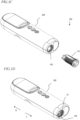
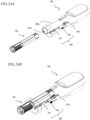
- FIG. 1A is a perspective view showing the external appearance of a drug injection system 300 including a drug cartridge 100 and a drug injection device 200.
- FIG. 1B to FIG. 1H is a perspective view showing the drug injection system 300 in one state during use.
- a skin contact surface 201b is further provided at the end face of the outer case 201 on which the cartridge opening 201a is provided.
- a display window 201d, an injection button 254, a select (up) button 255, a select (down) button 256 and a back button 257 are arranged on the outer case 201.
- the side of each component closer to the injection needle 12 may be referred to as "front” and the side of each component away from the injection needle 12 as “rear”. Instead of “before” and “after,” they may be referred to as “first” and “second”, or “second” and “first”.
- the operator picks the needle guard 130 of the drug cartridge 100 and removes the drug cartridge 100 from the drug injection device 200.
- the injection needle 12 of the drug cartridge 100 is covered by the needle guard 130. Therefore, the injection needle 12 is suppressed from coming into contact with a part of the body, such as a finger.
- the door 203 closes the cartridge opening 201a, as shown in FIG. 1H .
- the operator can load the drug cartridge 100 into the drug injection system 300 and remove the used drug cartridge 100 without touching the injection needle 12 with no special attention. Since the pre-filled syringe 10 is filled with the drug and the injection needle is attached, injection can be done in a clean (sterile) state at the time of manufacture.
- the structure of the drug cartridge 100 and the drug injection device 200 will now be described in detail.
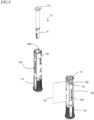
- FIG. 2 is an exploded perspective view of the pre-filled syringe 10.
- the pre-filled syringe 10 includes a syringe barrel 11, the injection needle 12, a stopper 13 and a needle shield 14.
- the syringe barrel 11 includes a syringe columnar space 11s and a syringe opening 11a located at one end of the syringe columnar space 11s, and the syringe columnar space 11s is filled with the drug.
- the injection needle 12 is located on the opposite side of the syringe barrel 11 from the syringe opening 11a, and is in communication with the syringe columnar space 11s.
- the syringe barrel 11 has a flange 11b provided on the syringe opening 11a side.
- the stopper 13 is arranged on the syringe opening 11a side of the syringe columnar space 11s.
- the stopper 13 is movable along the axis of the columnar shape within the columnar space of the syringe barrel 11, and when the piston 221 of the drug injection device 200 described below pushes the stopper 13, the drug is released from the tip of the injection needle 12.
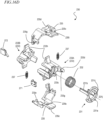
- the drug cartridge 100 includes the cap 110, the cassette outer sheath 120, the needle guard 130, a cassette spring 140, a sleeve 150 and a syringe retaining sheet 160.
- the components other than the cassette spring 140 are made of resin, for example.
- the cassette spring 140 is made of, for example, a steel material.
- the drug cartridge 100 has a cylindrical shape.
- the direction parallel to the axis a of the cylindrical shape of the drug cartridge 100 is referred to as the axial direction A.
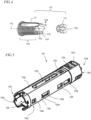
- FIG. 4 is an exploded perspective view of the cap 110.
- the cap 110 includes a cap main body 111 and a cap spring 112.
- the cap main body 111 includes a cylindrical trunk portion 111c, an elastic support portion 111d (the first elastic support portion), and an engagement claw 111e (the first engagement claw).
- the cap main body 111 includes a pair of elastic support portions 111d.
- a pair of elastic support portions 111d are arranged separated from each other in the radial direction with respect to an axis 111j of the cylindrical trunk portion 111c, and one end of each is located at one end of the trunk portion 111c.
- An engagement claw 111e is located at the other end of each elastic support portion 111d.
- the engagement claw 111e has a contact surface 111f on the outer side in the radial direction.
- the elastic support portion 111d can flex toward the center of the radial direction R.
- the cap spring 112 is arranged in the trunk portion 111c of the cap main body 111.
- the cap spring 112 includes a plurality of claws 112c.
- the claws 112c are arranged so that their tips point toward the tip of the trunk portion 111c and toward the axis 111j in the space within the trunk portion 111c.
- the claw 112c can mate with the engaging portion 14a of the needle shield 14 of the pre-filled syringe 10.
- FIG. 5 is a perspective view of the cassette outer sheath 120.
- the cassette outer sheath 120 has a cylindrical shape.
- the cassette outer sheath 120 is composed of flat portions 120p and 120q, which are generally flat, and curved portions 120r and 120s, which have a partially cylindrical side surface shape.
- the curved portions 120r and 120s connect together the flat portions 120p and 120q. With such a shape, the drug cartridge 100 is less likely to roll on a desk, etc.
- the loading angle the angle of rotation around the axis of the cylindrical shape
- the cassette outer sheath 120 includes a cassette rear opening 120b located at the rear end, a cassette front opening 120a located at the front end, and a cassette columnar space 120c located between the cassette rear opening 120b and the cassette front opening 120a.
- the cassette outer sheath 120 further includes a pair of sleeve engagement portions 120k on the inner surface on the side of the cassette rear opening 120b ( FIG. 9A ).
- the sleeve engagement portions 120k may be openings, claws, recesses, etc.
- the cassette outer sheath 120 includes a cap engagement portion 120d, a first opening 120f, a second opening 120e, a third opening 120g, a window 120h, a recess 120i, a slit 120j and a piston unit engagement portion 120n.
- the cassette outer sheath 120 includes two each of cap engagement portions 120d, second openings 120e, first openings 120f and third openings 120g.
- One each of the cap engagement portion 120d, the second opening 120e, the first opening 120f and the third opening 120g are provided on the curved portion 120r and on the curved portion 120s.
- the cap engagement portion 120d, the second opening 120e, the first opening 120f and the third opening 120g are aligned in a row parallel to the axis of the cylindrical shape of the cassette outer sheath 120.
- the cap engagement portion 120d is located on the cassette front opening 120a side of the cassette outer sheath 120.
- the first opening 120f is located on the cassette rear opening 120b side of the cassette outer sheath 120.
- the second opening 120e is located on the cassette front opening 120a side of the cassette outer sheath 120 relative to the first opening 120f.
- the third opening 120g is located on the cassette rear opening 120b side relative to the first opening 120f.
- the cap engagement portion 120d is a recess, an opening, a protrusion, etc., capable of engaging with an engagement claw, a protrusion, etc.
- an engagement portion is a recess, an opening, a protrusion, etc., capable of engaging with an engagement claw, a protrusion, etc., unless a particular shape is mentioned.
- Each of the first opening 120f, the second opening 120e and the third opening 120g is a through opening reaching the outer surface and the inner surface of the cassette outer sheath 120.
- the cassette outer sheath 120 further includes an in-opening protrusion 120m protruding from an edge of the second opening 120e on the cassette front opening 120a side toward the center of the second opening 120e.
- the window 120h, the recess 120i and the slit 120j are located on the flat portion 120p.
- the window 120h for example, has a length along the axis of the cassette outer sheath 120.
- the slit 120j is located on the cassette rear opening 120b side of the cassette outer sheath 120 and extends in a direction perpendicular to the axis of the cassette outer sheath 120.
- the recess 120i is located, for example, between the window 120h and the slit 120j.
- the piston unit engagement portion 120n engages with a piston unit 286 of the drug injection device 200, as described below.
- the piston unit engagement portion 120n is an opening.
- the guard portion 130c has a cylindrical shape that defines a needle guard columnar space that can house a portion of the syringe barrel 11 of the pre-filled syringe 10 .
- the guard portion 130c includes an end face portion 130cf and a needle guard opening 130a provided at the end face portion 130cf.
- the needle guard 130 includes a pair of protrusions 130e and a pair of elastic support portions 130d, and the pair of elastic support portions 130d are arranged in symmetry with an axis 130j of the needle guard 130 interposed therebetween.
- the protrusion 130e includes a slope portion 130ea located on the guard portion 130c side and sloping outward, i.e., toward the cassette outer sheath 120 as the needle guard 130 is inserted into the cassette outer sheath 120, a recess 130eb located on the slope portion 130ea, a top portion 130ec adjacent to the slope portion 130ea, a side portion 130ed adjacent to the top portion 130ec on the opposite side of the slope portion 130ea in the direction in which the elastic support portion 130d extends, and an inner surface portion 130ef located inward relative to the slope portion 130ea, the top portion 130ec and the side portion 130ed.
- FIG. 7 is an exploded perspective view of the sleeve 150.
- the sleeve 150 includes an inner cylinder portion 151 and a sleeve main body 152.
- the inner cylinder portion 151 has a cylindrical shape having a space that houses a portion of the pre-filled syringe, and includes a sleeve front opening 151a on the front bottom surface of the cylindrical shape.
- the inner cylinder portion 151 also includes a pair of slits 151e on the side surface of the cylindrical shape.
- the slits 151e have a length in a direction parallel to an axis 150j.
- the sleeve main body 152 includes an outer cylinder portion 152c and a base portion 152d.
- the sleeve main body 152 includes a pair of outer cylinder portions 152c.
- the pair of outer cylinder portions 152c are connected to the front end of the base portion 152d.
- a sleeve rear opening 152b is provided on the rear side of the base portion 152d.
- Each of the outer cylinder portions 152c has a partially cylindrical side surface shape. These outer cylinder portions 152c are arranged in symmetry with the axis 150j of the sleeve 150 interposed therebetween. A wedge-shaped portion 152j is provided at the tip of each outer cylinder portion 152c to disengage the engagement between the engagement claw llle of the cap 110 and the cap engagement portion 120d of the cassette outer sheath 120. Each outer cylinder portion 152c has a slit 152e having a length in a direction parallel to the axis 150j.
- the sleeve main body 152 further includes an elastic support portion 152f, an engagement claw 152g (the second engagement claw) and a protrusion 152i.
- the sleeve main body 152 includes a pair of elastic support portions 152f, the engagement claw 152g and the protrusion 152i.
- One end of each of the pair of elastic support portions 152f is connected near the sleeve rear opening 152b.
- the engagement claw 152g is connected to the other end of the elastic support portion 152f.
- the engagement claw 152g has a contact surface 152h on the outer side in the radial direction.
- the elastic support portion 152f can flex in the radial direction.
- the protrusion 152i is provided on the base portion 152d adjacent to the slit 152e.
- the inner cylinder portion 151 is connected to the front end of the base portion 152d of the sleeve main body 152. As shown in FIG. 3 , a pair of outer cylinder portions 152c are arranged separated from each other in the radial direction centered on the axis 150j with respect to the inner cylinder portion 151. The slit 151e of the inner cylinder portion 151 and the slit 152e of the outer cylinder portion 152c are aligned in the radial direction. As described below, the needle guard 130 is inserted between the inner cylinder portion 151 and the outer cylinder portion 152c.
- the components of the drug cartridge described above are assembled in the arrangement shown in FIG. 3 .
- the cap 110 is fitted into the cassette front opening 120a of the cassette outer sheath 120.
- the needle guard 130 is inserted between the inner cylinder portion 151 and the outer cylinder portion 152c of the sleeve 150 with the cassette spring 140 inserted within the needle guard columnar space.
- the needle guard 130, the cassette spring 140 and the sleeve 150 are inserted into the cassette columnar space 120c of the cassette outer sheath 120.
- the pre-filled syringe 10 is inserted into the cassette 105 thus assembled. As shown in FIG. 8 , the pre-filled syringe 10 is inserted through the cassette rear opening 120b of the cassette outer sheath 120, the needle shield 14 first. By inserting the flange 11b of the syringe barrel 11 into the slit 120j of the cassette outer sheath 120 and similarly inserting the outer edge of the syringe retaining sheet 160 into the slit 120j, the pre-filled syringe 10 is retained in the cassette outer sheath 120.
- the pre-filled syringe 10 held inside can be seen through the window 120h of the cassette outer sheath 120. It is also possible to check if the pre-filled syringe 10 is filled with the drug.
- a label 192 may be affixed to the outer surface of the cassette outer sheath 120, indicating information regarding the type and amount of drug filled in the pre-filled syringe 10, as well as the date of manufacture and expiration date of the pre-filled syringe 10. If the drug cartridge 100 has the label 192 thereon, the label 192 preferably does not cover the window 120h.
- a radio tag 190 may be provided in the recess 120i of the cassette outer sheath 120.
- the radio tag 190 is also called RFID (Radio Frequency Identification) and is capable of transmitting and receiving information by short-range communication using, for example, UHF or HF band radio waves.
- the radio tag 190 has a memory that stores, for example, information regarding the type and amount of drug filled in the pre-filled syringe 10, as well as the date of manufacture and expiration date of the pre-filled syringe 10.
- the radio tag 190 is covered by a seal 191.
- the radio tag 190 may be of a type that allows information to be appended or rewritten from outside in order to record usage. In this case, the radio tag 190 preferably has a security function, such as being able to append or rewrite information only from an authenticated writer, so that the recorded information cannot be tampered with.
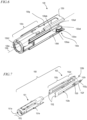
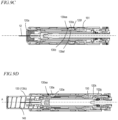
- FIG. 9A to FIG. 9D are schematic cross-sectional views through the axis A of the drug cartridge 100 in various states.
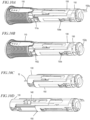
- FIG. 10A to FIG. 10D are perspective views of the drug cartridge 100 corresponding to the states shown in FIG. 9A to FIG. 9D , respectively, with the cassette outer sheath 120 removed.
- a part of the structure of the drug cartridge 100 is not shown in FIG. 9A to FIG. 9D .
- the drug cartridge 100 is in a state prior to loading into the drug injection device 200.
- the pre-filled syringe 10 is unmovably supported in the cassette columnar space by inserting the flange 11b of the syringe barrel 11 into the slit 120j of the cassette outer sheath 120.
- a part of the injection needle 12 and a part of the needle shield 14 of the pre-filled syringe 10 protrude from the cassette front opening 120a.
- the cap 110 is fitted into the cassette front opening 120a of the cassette outer sheath 120.
- the cap main body 111 surrounds the cassette front opening 120a, and the engagement claw 111e is inserted through the cassette front opening 120a into the cassette outer sheath 120 and engages with the cap engagement portion 120d of the cassette outer sheath 120.
- the cap 110 cannot be detached from the cassette front opening 120a.
- the cap 110 is mated with the needle shield 14 and covers the needle shield 14.
- the sleeve 150 is arranged outside the syringe barrel 11 of the pre-filled syringe 10 and is movable in the cassette columnar space in the axial direction A.
- the sleeve 150 In the initial state, as shown in FIG. 9A , the sleeve 150 is arranged in the first position on the cassette rear opening 120b side.
- the engagement claw 152g of the sleeve 150 engages with the sleeve engagement portion 120k located on the inner surface of the cassette outer sheath 120 on the cassette rear opening 120b side, and the sleeve 150 is engaged with the cassette outer sheath 120.
- the sleeve 150 is suppressed from moving to the second position, which is the forward position.
- the needle guard 130 is movable in the cassette columnar space in the axial direction A, and in the initial state, the needle guard 130 is arranged in the first engagement position, where the tip of the guard portion 130c has moved backward relative to the tip of the injection needle 12 protruding from the cassette front opening 120a. In this state, the protrusion 130e of the needle guard 130 is engaged with the first opening 120f of the cassette outer sheath 120.
- the operator can remove the cap 110 with their fingers.
- the needle shield 14 is also removed together.
- the display device 258 displays information of the pre-filled syringe 10 held in the drug cartridge 100, displays the status of the drug injection device 200 and displays the operating procedures for the operator.
- the battery 252 supplies power to operate the drug injection device 200.
- the rotary encoder 266 includes an encoder plate 266A and a pulse encoder 266B, wherein the encoder plate 266A is attached to the rotary shaft of the injection motor 265.
- the encoder plate 266A has notches arranged at equal intervals along the circumference.
- the pulse encoder 266B includes a light-emitting element and a light-receiving element, and is arranged so that the outer circumference of the encoder plate 266A is positioned between the light-emitting element and the light-receiving element.
- the rotary encoder 266 generates a pulse signal having a pulse number corresponding to the number of revolutions (amount of rotation) of the injection motor 265, and detects the number of revolutions of the injection motor 265.
- the notch is twisted at the tip portion 221a, and the piston 221 has a helical contact surface at the tip portion 221a.
- the piston 221 includes a pair of first flat surfaces 222a that sandwich the piston axis 221j therebetween at the base portion 221b.
- the piston 221 includes a pair of second flat surfaces 222b and a pair of third flat surfaces 222c at the tip portion 221a.
- the second flat surface 222b is located between the first flat surface 222a and the third flat surface 222c, and the third flat surface 222c is located furthest on the tip side of the piston 221.
- a protrusion 235e and a recess 235g are provided at opposite ends of the pair of cartridge latches 235 in the circumferential direction adjacent to the cartridge latch spring 237, with the protrusion 235e of one cartridge latch 235 loosely mating with the recess 235g of the other cartridge latch 235.
- the cartridge latch spring 237 swings.
- the engagement portions of the protrusion 235e and the recess 235g function as an axis, the cartridge latch spring 237 expands and contracts stably, and the cartridge latch spring 237 can swing smoothly.
- the cartridge latch 235 may be provided with an emergency contact portion 235s.
- the protrusions 235c of a pair of cartridge latches 235 are moved inward by pressing the contact portion 235s from outside.
- the engagement between the protrusion 235c and the cassette outer sheath 120 of the drug cartridge can be disengaged from outside.
- the screw 206 can be removed from the emergency hole 201Bc ( FIG. 12A ), and an elongated pin can be inserted through the emergency hole 201Bc to push the contact portion 235s and swing the pair of cartridge latches 235.
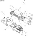
- FIG. 15 When the drive gear 212 of the motor unit 285 rotates, the piston gear 224 ( FIG. 16A ) meshed with the drive gear 212 rotates. Accordingly, the piston 221 moves forward or moves backward. At this point, while a pair of restricting portions 233e protruding in the through hole 233c of the latch unit 230 are located at the base portion 221b, the first flat surface 222a of the piston 221 and the restricting portions 233e are close to each other or in contact with each other, and the latch unit 230 does not rotate.
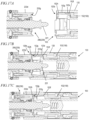
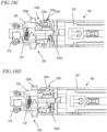
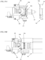
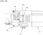
- FIG. 17A to FIG. 17C , FIG. 18A to FIG. 18D and FIG. 19A to FIG. 19C are diagrams illustrating how the piston unit 286 grips the drug cartridge 100.
- FIG. 17A to FIG. 17C show a cross sectional passing through the arms 233d of the latch unit 230
- FIG. 18A to FIG. 18D show the outer cassette cylinder 120 of the drug cartridge 100 in cross section
- FIG. 19A to FIG. 19C are diagrams thereof as viewed from the side surface.
- insertion of the drug cartridge 100 into the drug injection device 200 proceeds, and the tip of the piston unit 286 is inserted into the cassette outer sheath 120 through the cassette rear opening 120b of the cassette outer sheath 120 of the drug cartridge 100.
- the sleeve contact portion 233g of an arm 233d of the piston unit 286 contacts the contact surface 152h of the engagement claw 152g located in the vicinity of the sleeve rear opening 152b of the sleeve 150, and the elastic support portion 152f flexes inward.
- the engagement between the sleeve engagement portion 120k of the cassette outer sheath 120 and the engagement claw 152g is disengaged.
- the piston unit 286 When the drug cartridge 100 is further inserted into the drug injection device 200, the piston unit 286 relatively moves toward the front end of the drug cartridge 100, and the sleeve 150 is also pushed by the piston unit 286 to move toward the front end. At this point, as shown in FIG. 18B , the protrusion 235c of the latch unit 230 is not inserted into the cassette outer sheath 120. The cartridge loading detector 271 and the cartridge lock detector 272 remain OFF.
- the contact surface 235t of the protrusion 235c contacts the inner edge of the cassette rear opening 120b, causing the cartridge latch 235 to rotate inward about the shaft 235d against the biasing force of the cartridge latch spring 237.
- the protrusion 235c is inserted into the cassette outer sheath 120 through the cassette rear opening 120b, as shown in FIG. 18C .
- the cartridge lock detector 272 is turned ON by detecting the pivoting of the cartridge latch 235. As shown in FIG. 19B , at this point, the cartridge loading detector 271 remains OFF.
- the protrusion 235c engages with the piston unit engagement portion 120n, as shown in FIG. 18D .
- the cartridge latch 235 rotates outward about the shaft 235d by the biasing force of the cartridge latch spring 237.
- the cartridge lock detector 272 is turned OFF.
- the protrusion 235c of the cartridge latch 235 engages with the piston unit engagement portion 120n, thereby completing the gripping of the drug cartridge 100 by the piston unit 286, and completing the loading of the drug cartridge 100 into the drug injection device 200. Since the protrusion 235c of the cartridge latch 235 is biased outward by the cartridge latch spring 237, the protrusion 235c remains inserted in the piston unit engagement portion 120n, which is an opening. That is, the piston unit 286 is locked while gripping the drug cartridge 100. As shown in FIG. 19C , at this point, the cartridge loading detector 271 detects complete loading of the drug cartridge 100 to be turned ON.
- the cartridge loading detector 271 detecting that the cartridge is in the correct position at completion of loading and the cartridge lock detector 272 detecting that the latch unit 230 has operated, it is possible to correctly detect the loading of the drug cartridge 100 and the gripping of the drug cartridge 100 by the piston unit 286.
- FIG. 20A , FIG. 21A and FIG. 22A are perspective views showing the vicinity of the engaging portion between the piston unit 286 and the drug cartridge 100 at the time of releasing the drug cartridge 100 by the piston unit 286.
- FIG. 20B , FIG. 21B and FIG. 22B corresponding to FIG. 20A , FIG. 21A and FIG. 22A , respectively, are perspective views of the drug cartridge 100 with the cassette outer sheath 120 removed.
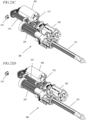
- FIG. 20A and FIG. 20B show the state where the piston unit 286 is gripping the drug cartridge 100.
- the sleeve contact portion 233g of the arm 233d of the piston unit 286 is in contact with the contact surface 152h of the engagement claw 152g of the sleeve 150, and the elastic support portion 152f is flexed inward.
- the protrusion 235c of the cartridge latch 235 is inserted into the piston unit engagement portion 120n, which is an opening.
- the piston 221 moves backward to the needle guard ejection position and the cartridge ejection position to rotate the latch unit 230 around the piston axis 221j.
- the piston 221 has an I-shaped cross section, and is twisted over the tip portion 221a.
- the latch unit 230 rotates counterclockwise as viewed from the tip side in accordance with the orientations of the helical surface 222d, the second flat surface 222b, the helical surface 222e and the third flat surface 222c.
- FIG. 21A and FIG. 21B show the state after the sleeve 150 moves backward.
- the protrusion 235c of the cartridge latch 235 also rotates counterclockwise as viewed from the tip, but a part of the protrusion 235c is still located within the opening of the piston unit engagement portion 120n.
- the drug cartridge 100 is gripped by the piston unit 286.
- FIG. 23A to FIG. 23F are perspective views of the driver device 284.
- the piston case 220 is not shown in these figures.
- the tip portion 221a of the piston 221 is in a position further forward than the latch base 233 of the latch unit 230.
- the needle insertion/removal motor 268 rotates the drive screw 214.
- the piston unit 286 moves forward. Since the tooth width of the spur gear of the piston gear 224 is wide, the drive gear 212 and the piston gear 224 remain meshed with each other even when the piston unit 286 moves forward.
- the injection motor 265 rotates the drive gear 212, and the piston gear 224, which is meshed with the drive gear 212 rotates.
- the piston 221 moves forward, and the piston 221 causes the stopper 13 ( FIG. 2 ) of the pre-filled syringe to move forward. This allows the drug to be administered to the operator.
- the injection motor 265 reverses the drive gear 212, and the piston gear 224, which is meshed with the drive gear 212, also reverses. This causes the piston 221 to move backward to the needle guard ejection position.
- the latch unit 230 rotates counterclockwise by an angle of ⁇ 1 as viewed from the tip side. In the state shown in FIG.
- the second flat surface 222b close to or in contact with the restricting portion 233e, which is located in the through hole 233c of the latch base 233, and the contact between the sleeve contact portion 233g of the arm 233d of the piston unit 286 and the contact surface 152h of the elastic support portion 152f of the engagement claw 152g of the sleeve 150 is disengaged.
- the sleeve 150 moves from the second position to the first position, and the needle guard 130 is ejected. Detection of the ejection of the needle guard 130 is done by the needle guard detector 276.
- the piston 221 further moves backward to the cartridge ejection position, and the latch unit 230 also further rotates counterclockwise by an angle of ( ⁇ 2- ⁇ 1). That is, the latch unit 230 has rotated by an angle of ⁇ 2 from its initial state.
- the third flat surface 222c comes close to or into contact with the restricting portion 233e located in the through hole 233c of the latch base 233, and the protrusion 235c of the cartridge latch 235 is detached from the opening of the piston unit engagement portion 120n.
- the drug cartridge 100 is released from the piston unit 286.
- the rear end of the piston 221 presses down the origin detector 279, and the origin detector 279 detects that the piston 221 has moved backward to the origin position. Based on the output of the origin detector 279, the injection motor 265 stops and the piston 221 also stops moving backward.
- the injection motor 265 causes the drive gear 212 to rotate forward, and the piston gear 224, which is engaged with the drive gear 212, also rotates forward.
- the piston 221 moves forward to the initial position.
- the initial position is determined by a predetermined amount of movement based on the pulse output of the rotary encoder, using the position stopped by the origin detector 279 as the origin.
- the slider unit 288 biases the drug cartridge 100 inserted into the drug injection device 200 in the direction of ejection (forward).
- the slider unit 288 includes a slide member 241 adjacent to the cartridge space 280a and supported by the lower casing 280B ( FIG. 13 ) so that it can move in the direction in which the cartridge space 280a extends, and a biasing member 242 that biases the slide member toward the front end of the drug injection device 200.
- the biasing member 242 is a torsion spring.
- the slide member 241 includes an engagement projection 241c on the rear end side.
- the biasing member 242 is biasing the slide member 241 toward the front end side.
- the rear end of the cassette outer sheath 120 of the drug cartridge 100 engages with the engagement projection 241c, as shown in FIG. 24B .
- the slide member 241 moves together with the drug cartridge 100 toward the rear end side, against the biasing force of the biasing member 242.
- the piston unit 286 grips the drug cartridge 100 and the loading of the drug cartridge 100 is completed.
- the slide member 241 is biased in the front end direction by the biasing member 242, but the drug cartridge 100 does not move because of the gripping by the piston unit 286.
- the drug cartridge 100 moves forward together with the slide member 241, which is biased toward the front end by the biasing member 242. As shown in FIG. 24E , the needle guard 130 of the drug cartridge 100 protrudes significantly from the cartridge opening 201a of the drug injection device 200, making it easier for the operator to pick and pull out the drug cartridge 100.
- FIG. 25A and FIG. 25B are perspective views of the driver device 284 with the piston unit 286 gripping the drug cartridge 100.
- the piston case 220 of the piston unit 286 includes a light-blocking portion 220d.
- the needle insertion completion detector 227 and the needle removal completion detector 278 are, for example, photo interrupters.
- the needle removal completion detector 278 detects the light-blocking portion 220d at the initial position of the drug cartridge 100, i.e., at the position where the drug cartridge 100 has been loaded into the drug injection device 200.
- the needle insertion completion detector 227 detects the light-blocking portion 220d at the position where the piston unit 286 has moved forward and the needle insertion is complete.
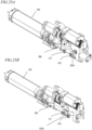
- the needle guard detector 276 when detecting the reflective portion 130r located at the rear end of the needle guard 130, the needle guard detector 276 is arranged at a position close to the window 120h of the cassette outer sheath 120 of the drug cartridge 100 loaded in the drug injection device 200.
- the needle guard detector 276 may be located in the upper casing 280A or may be arranged on the flexible board 282 on which the antenna of the RF-ID reader/writer 263 is provided.
- the operator loads the drug cartridge 100 into the drug injection device 200 (S10).
- the drug injection device 200 identifies the loaded drug cartridge 100 (S20).
- the operator removes the cap 110 of the drug cartridge 100 (S30) and places the drug injection device 200 in contact with the skin (S40).
- the needle guard 130 is ejected (S100).
- the termination process is performed (S120). The subflows will be described in detail below.
- the control circuit 251 After the main power is turned ON, the control circuit 251 detects that the cartridge loading detector 271 is turned ON and the cartridge lock detector 272 is turned OFF (S14) in the order shown in Table 2 to detect that the drug cartridge 100 is correctly loaded. Note that as shown in Table 2, it can be confirmed that the drug cartridge 100 has been correctly loaded into the drug injection device 200 if only the cartridge loading detector 271 is ON and the cartridge lock detector 272 is OFF, so the main power may be turned ON to switch from the standby mode to the operating mode at the timing when the cartridge loading detector 271 or the cartridge lock detector 272 is turned ON. Then, the control circuit 251 displays the startup screen on the display device 258 (S15), and the process returns to the main flow.
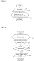
- the control circuit 251 causes the display device 258 to display a prompt for the operator to remove the cap 110 (S31). For example, the display device 258 is made to display text information such as "Remove cap”. A graphic or animated display may be provided.
- the operator removes the cap 110 (S32).
- the control circuit 251 detects that the cap detector 275 is turned off (S33) and uses the RF-ID reader/writer 263 to write a flag to the radio tag 190 of the drug cartridge 100 indicating that it has been used.
- S33 the cap detector 275 is turned off
- the RF-ID reader/writer 263 uses the RF-ID reader/writer 263 to write a flag to the radio tag 190 of the drug cartridge 100 indicating that it has been used.
- the control circuit 251 causes the display device 258 to display information prompting the operator to wait for a while (S101). For example, the control circuit 251 causes the display device 258 to display a message such as "Wait for a moment”. Then, the injection motor 265 is reversed (S102), and the piston is moved backward to the needle guard discharge position, which is further backward than the initial position.
- the control circuit 251 determines from the output of the rotary encoder whether the piston 221 has moved backward to the needle guard ejection position (S103). Specifically, the control circuit 251 determines whether the piston 221 has moved backward to the needle guard ejection position where the contact between the sleeve 150 of the drug cartridge 100 and the latch unit 230 is disengaged as described above. If the control circuit 251 detects that the piston 221 has moved backward to the needle guard discharge position, the control circuit 251 stops the injection motor 265 (S104).
- the sleeve 150 of the drug cartridge 100 moves to the first position and the needle guard 130 is unlocked in the first engagement position, causing the needle guard 130 to move from the first engagement position to the second engagement position. That is, the needle guard 130 is ejected.
- the control circuit 251 determines whether the needle guard detector 276 has detected the ejection of the needle guard 130 (S105). If detected, this flow is terminated. If the ejection of the needle guard 130 cannot be detected, the display device 258 displays a message indicating that the needle guard has not been ejected (S106) to wait until ejection is detected. If the ejection of the needle guard 130 is not detected even after a certain period of time, the control circuit 251 may perform a process of abnormal termination by terminating this flow and discontinuing the processing of the main flow ( FIG. 27 ). For example, the control circuit 251 causes the display device 258 to display a message indicating that an abnormality has occurred in the drug injection device 200 and prompting the operator to contact their treating physician, or other person.
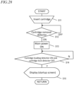
- the control circuit 251 causes the display device 258 to display information that alerts the operator that an operation of removing the drug cartridge 100 is to be performed (S111). For example, the control circuit 251 causes the display device 258 to display a message such as "Ejecting cartridge”. Then, the control circuit 251 reverses the injection motor 265 (S112). This causes the piston 221 to move backward to the cartridge ejection position, which is further backward from the needle guard ejection position. As the piston moves backward, the latch unit 230 rotates further around the piston axis 221j, disengaging the engagement between the cartridge latch 235 and the cassette outer sheath 120. This releases the drug cartridge 100 from the piston unit 286 and allows the drug cartridge 100 to be removed.
- the control circuit 251 determines whether the origin detector 279 is in contact with the piston 221, i.e., whether the piston 221 has moved backward to the origin position (S113). If the origin detector 279 detects contact with the piston 221, the control circuit 251 stops the injection motor 265 (S114).
- the control circuit 251 further determines whether the cartridge loading detector 271 detects the loading of the drug cartridge 100 (S115). If loading of the drug cartridge 100 is not detected, i.e., the drug cartridge 100 has been released from the piston unit 286, the control circuit 251 causes the display 258 to display information prompting the operator to remove the cartridge (S116). For example, the control circuit 251 causes the display device 258 to display a message such as "Remove cartridge".
- control circuit 251 determines whether the cartridge removal detector 273 detects contact with the drug cartridge 100 (S118). If not detected, the drug cartridge 100 has been removed and this flow is terminated.
- the control circuit 251 terminates this flow, discontinues the processing of the main flow ( FIG. 27 ), and performs the abnormal termination process described above.
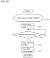
- the control circuit 251 causes the display device 258 to display that alerts the operator of the next injection schedule (S121). For example, the control circuit 251 causes the display device 258 to display a message such as "Next injection date is XX/XX". The control circuit 251 also causes the injection motor 265 to rotate forward (S122).
- the various detectors detect various states during the injection operation to alert the operator of the next operation according to the detection results. Therefore, the operator can perform the operation of injecting the drug easily and with peace of mind without having anxiety about whether the operation procedure is correct or not.
- the injection needle 12 is covered by the needle guard 130 and is not exposed during a series of operations of injecting the drug, removing the drug cartridge 100 from the drug injection device 200 and disposing the drug cartridge 100.
- the operator can use the drug injection system 300 with peace of mind, without having to take special precautions against pricking their fingers with the injection needle 12 or catching clothing with the exposed injection needle 12.
- the structure of the drug cartridge 100 and the drug injection device 200 described in the embodiment above is an example, and various modifications are possible.
- the information displayed on the display device as described in the embodiment above is only one example, and other contents may be displayed, or the operator may be alerted by sounding a buzzer instead of or in conjunction with the display on the display device.
- a drug cartridge without the pre-filled syringe 10 may be provided as a training drug cartridge.
- Such a training drug cartridge operates in the same manner as the drug cartridge 100, except that by not including the pre-filled syringe 10, the needle cannot actually be inserted/removed and the drug is not administered. Therefore, an operator new to handling the drug injection device 200 can use such a training drug cartridge for training to become familiar with its handling.
- the drug cartridge, the drug injection device and the drug injection system of the present disclosure are suitably used in various drug injecting devices.
Landscapes
- Health & Medical Sciences (AREA)
- Engineering & Computer Science (AREA)
- Heart & Thoracic Surgery (AREA)
- Vascular Medicine (AREA)
- Anesthesiology (AREA)
- Biomedical Technology (AREA)
- Hematology (AREA)
- Life Sciences & Earth Sciences (AREA)
- Animal Behavior & Ethology (AREA)
- General Health & Medical Sciences (AREA)
- Public Health (AREA)
- Veterinary Medicine (AREA)
- Environmental & Geological Engineering (AREA)
- Infusion, Injection, And Reservoir Apparatuses (AREA)
Abstract
Description
- The present application relates to a drug cartridge, a drug injection device and a drug injection system for injecting a drug.
- Treatment by self-injection, in which a patient injects himself/herself, is becoming popular, and drug injection devices for self-injection have been developed. Pre-filled syringes are known as a type of syringe used for such self-injection. A pre-filled syringe is a syringe that has been pre-filled with a drug and an injection needle may also be attached to the syringe. The use of pre-filled syringes eliminates the need for the patient to fill the drug and attach the injection needle, and allows the drug to be injected while maintaining the cleanliness of the pre-filled syringe at the time of its manufacture. For example, Patent Document No. 1 discloses a drug injection device that uses such a pre-filled syringe.
- Patent Document No. 1:
Japanese National Phase PCT Laid-open Publication No. 2014-516634 - There is a demand for a drug injection device that has better operability and safety. A non-limiting illustrative embodiment of the present application provides a drug injection device and a drug injection system with superior operability and safety, and a drug cartridge for use therewith.
- A drug cartridge according to one embodiment of the present disclosure includes: a pre-filled syringe including a drug, a syringe barrel having a syringe columnar space in which the drug is arranged and a syringe opening located at one end of the syringe columnar space, an injection needle located on an opposite side of the syringe barrel from the syringe opening and being in communication with the syringe columnar space, a stopper movable in the syringe columnar space and arranged on the syringe opening side, and a needle shield that covers a tip of the injection needle and is removable; a cassette outer sheath including a cassette front opening, a cassette rear opening and a cassette columnar space located between the cassette rear opening and the cassette front opening, wherein the cassette outer sheath holds the pre-filled syringe in the cassette columnar space so that a part of the injection needle and a part of the needle shield protrude from the cassette front opening; a cap mated with the needle shield and fitted into the cassette front opening so as to cover the needle shield, wherein the cap is removable from the cassette outer sheath together with the needle shield; a needle guard including a guard portion and movable in an axis direction of the cassette columnar space in the cassette columnar space, wherein the needle guard is movable between a first engagement position and a second engagement position, wherein in the first engagement position, a front end of the guard portion is further backward than the tip of the injection needle protruding from the cassette front opening, and in the second engagement position, the front end of the guard portion protrudes from the tip of the injection needle protruding from the cassette front opening where the cap is detached; a sleeve movable in the axis direction in the cassette columnar space between a first position located on the cassette rear opening side and a second position located on the cassette front opening side relative to the first position, wherein the sleeve is engaged with the cassette outer sheath in the first position; and a cassette spring that biases the needle guard toward the cassette front opening, wherein when the cap is fitted into the cassette front opening, the cap is capable of assuming a locked state where the cap cannot be detached from the cassette outer sheath and an unlocked state where the cap can be detached from the cassette outer sheath.
- A drug injection device according to one embodiment of the present disclosure includes: a case including a cartridge space in which the above-mentioned drug cartridge can be loaded, and a cartridge opening in communication with the cartridge space; a piston unit including a piston, a piston gear that drives the piston in a piston axis direction, and a latch unit for gripping the drug cartridge, wherein a part of the latch unit is inserted into the cassette rear opening of the drug cartridge; a needle insertion/removal motor causing the piston unit to move forward and move backward in the piston axis direction; an injection motor causing the piston to move forward and move backward in the piston axis direction; a control circuit for controlling the needle insertion/removal motor and the injection motor; and an interface for inputting a command to the control circuit.
- According to at least one of the embodiments of the present disclosure, there is provided a drug injection device and a drug injection system with superior operability and safety, and a drug cartridge for use therewith.
-
-
FIG. 1A is a perspective view showing the external appearance of a drug injection system including a drug cartridge and a drug injection device. -
FIG. 1B is a perspective view showing the drug injection system in one state during use. -
FIG. 1C is a perspective view showing the drug injection system in one state during use. -
FIG. 1D is a perspective view showing the drug injection system in one state during use. -
FIG. 1E is a perspective view showing the drug injection system in one state during use. -
FIG. 1F is a perspective view showing the drug injection system in one state during use. -
FIG. 1G is a perspective view showing the drug injection system in one state during use. -
FIG. 1H is a perspective view showing the drug injection system in one state during use. -
FIG. 2 is an exploded perspective view of a pre-filled syringe. -
FIG. 3 is an exploded perspective view of a drug cartridge (excluding the pre-filled syringe). -
FIG. 4 is an exploded perspective view of a cap. -
FIG. 5 is a perspective view of a cassette outer sheath. -
FIG. 6 is a perspective view of a needle guard. -
FIG. 7 is an exploded perspective view of a sleeve. -
FIG. 8 is a diagram showing the procedure for assembling a drug cartridge. -
FIG. 9A is a schematic axial cross-sectional view showing the drug cartridge in one state. -
FIG. 9B is a schematic axial cross-sectional view showing the drug cartridge in one state. -
FIG. 9C is a schematic axial cross-sectional view showing the drug cartridge in one state. -
FIG. 9D is a schematic axial cross-sectional view showing the drug cartridge in one state. -
FIG. 10A is a perspective view of the drug cartridge in one state with the cassette outer sheath removed. -
FIG. 10B is a perspective view of the drug cartridge in one state with the cassette outer sheath removed. -
FIG. 10C is a perspective view of the drug cartridge in one state with the cassette outer sheath removed. -
FIG. 10D is a perspective view of the drug cartridge in one state with the cassette outer sheath removed. -
FIG. 11A is a perspective view of the drug cartridge with the needle guard protruding. -
FIG. 11B is a perspective view of the drug cartridge with the needle guard protruding. -
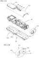
FIG. 12A is a perspective view where the outer case of the drug injection device is disassembled. -
FIG. 12B is a perspective view showing a tip case as viewed from inside. -
FIG. 13 is an exploded perspective view of the main body. -
FIG. 14 is a block diagram showing a configuration of an electric circuit of the drug injection device. -
FIG. 15 is a perspective view of the driver device. -
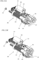
FIG. 16A is a perspective view of the piston unit with the piston case removed. -
FIG. 16B is an exploded perspective view of the piston unit with the piston case removed. -
FIG. 16C is a diagram showing the positional relationship between the first flat surface, the second flat surface and the third flat surface as viewed from the tip side. -
FIG. 16D is an exploded perspective view of the latch unit. -
FIG. 16E is a front view of the latch unit. -
FIG. 17A is a cross-sectional view illustrating the piston unit gripping a drug cartridge. -
FIG. 17B is a cross-sectional view illustrating the piston unit gripping a drug cartridge. -
FIG. 17C is a cross-sectional view illustrating the piston unit gripping a drug cartridge. -
FIG. 18A is a partial cross-sectional view illustrating the piston unit gripping a drug cartridge. -
FIG. 18B is a partial cross-sectional view illustrating the piston unit gripping a drug cartridge. -
FIG. 18C is a partial cross-sectional view illustrating the piston unit gripping a drug cartridge. -
FIG. 18D is a partial cross-sectional view illustrating the piston unit gripping a drug cartridge. -
FIG. 19A is a side view illustrating the piston unit gripping a drug cartridge. -
FIG. 19B is a side view illustrating the piston unit gripping a drug cartridge. -
FIG. 19C is a side view illustrating the piston unit gripping a drug cartridge. -
FIG. 20A is a perspective view showing the vicinity of the engagement portion between the piston unit and the drug cartridge when the drug cartridge is released by the piston unit. -
FIG. 20B is a perspective view showing the vicinity of the engagement portion between the piston unit and the drug cartridge when the drug cartridge is released by the piston unit. -
FIG. 21A is a perspective view showing the vicinity of the engagement portion between the piston unit and the drug cartridge when the drug cartridge is released by the piston unit. -
FIG. 21B is a perspective view showing the vicinity of the engagement portion between the piston unit and the drug cartridge when the drug cartridge is released by the piston unit. -
FIG. 22A is a perspective view showing the vicinity of the engagement portion between the piston unit and the drug cartridge when the drug cartridge is released by the piston unit. -
FIG. 22B is a perspective view showing the vicinity of the engagement portion between the piston unit and the drug cartridge when the drug cartridge is released by the piston unit. -
FIG. 23A is a perspective view of the driver device. -
FIG. 23B is a perspective view of the driver device. -
FIG. 23C is a perspective view of the driver device. -
FIG. 23D is a perspective view of the driver device. -
FIG. 23E is a perspective view of the driver device. -
FIG. 23F is a perspective view of the driver device. -
FIG. 24A is a perspective view illustrating the operation of the slider unit. -
FIG. 24B is a perspective view illustrating the operation of the slider unit. -
FIG. 24C is a perspective view illustrating the operation of the slider unit. -
FIG. 24D is a perspective view illustrating the operation of the slider unit. -
FIG. 24E is a perspective view illustrating the operation of the slider unit. -
FIG. 25A is a perspective view illustrating the needle insertion completion detector and the needle removal completion detector. -
FIG. 25B is a perspective view illustrating the needle insertion completion detector and the needle removal completion detector. -
FIG. 26A is a perspective view illustrating the needle guard detector. -
FIG. 26B is a perspective view illustrating the needle guard detector. -
FIG. 27 is a flow chart illustrating an operation of the drug injection system. -
FIG. 28 is a flow chart illustrating an operation of the drug injection system. -
FIG. 29 is a flow chart illustrating an operation of the drug injection system. -
FIG. 30 is a flow chart illustrating an operation of the drug injection system. -
FIG. 31 is a flow chart illustrating an operation of the drug injection system. -
FIG. 32 is a flow chart illustrating an operation of the drug injection system. -
FIG. 33 is a flow chart illustrating an operation of the drug injection system. -
FIG. 34 is a flow chart illustrating an operation of the drug injection system. -
FIG. 35 is a flow chart illustrating an operation of the drug injection system. -
FIG. 36 is a flow chart illustrating an operation of the drug injection system. -
FIG. 37 is a flow chart illustrating an operation of the drug injection system. -
FIG. 38 is a flow chart illustrating an operation of the drug injection system. -
FIG. 39 is a flow chart illustrating an operation of the drug injection system. - It is preferred that a drug injection device used by a patient to inject a drug themselves can be used properly without requiring skill. It is preferred that it is easy to operate and safe. The drug cartridge and the drug injection device of the present disclosure are compatible with a pre-filled syringe with an injection needle attached thereto, and suppress the possibility of the injection needle being exposed from the drug cartridge and the operator accidentally touching the injection needle other than during injection. The drug cartridge, the drug injection device and the drug injection system of the present disclosure will be outlined below.
- A drug cartridge including:
- a pre-filled syringe including a drug, a syringe barrel having a syringe columnar space in which the drug is arranged and a syringe opening located at one end of the syringe columnar space, an injection needle located on an opposite side of the syringe barrel from the syringe opening and being in communication with the syringe columnar space, a stopper movable in the syringe columnar space and arranged on the syringe opening side, and a needle shield that covers a tip of the injection needle and is removable;
- a cassette outer sheath including a cassette front opening, a cassette rear opening and a cassette columnar space located between the cassette rear opening and the cassette front opening, wherein the cassette outer sheath holds the pre-filled syringe in the cassette columnar space so that a part of the injection needle and a part of the needle shield protrude from the cassette front opening;
- a cap mated with the needle shield and fitted into the cassette front opening so as to cover the needle shield, wherein the cap is removable from the cassette outer sheath together with the needle shield;
- a needle guard including a guard portion and movable in an axis direction of the cassette columnar space in the cassette columnar space, wherein the needle guard is movable between a first engagement position and a second engagement position, wherein in the first engagement position, a front end of the guard portion is further backward than the tip of the injection needle protruding from the cassette front opening, and in the second engagement position, the front end of the guard portion protrudes from the tip of the injection needle protruding from the cassette front opening where the cap is detached;
- a sleeve movable in the axis direction in the cassette columnar space between a first position located on the cassette rear opening side and a second position located on the cassette front opening side relative to the first position, wherein the sleeve is engaged with the cassette outer sheath in the first position; and
- a cassette spring that biases the needle guard toward the cassette front opening,
- wherein when the cap is fitted into the cassette front opening, the cap is capable of assuming a locked state where the cap cannot be detached from the cassette outer sheath and an unlocked state where the cap can be detached from the cassette outer sheath.
- The drug cartridge according to item 1, wherein:
- where the cap is fitted into the cassette front opening; and
- the needle guard is in contact with the cap and is located in the first engagement position against a biasing force of the cassette spring.
- The drug cartridge according to item 2, wherein:
- where the cap is fitted into the cassette front opening and the sleeve is in the first position, the cap is locked; and
- where the cap is fitted into the cassette front opening and the sleeve is in the second position, the sleeve renders the cap in an unlocked state and the needle guard in a locked state in which the needle guard is unmovable in the first engagement position.
- The drug cartridge according to item 3, wherein:
- one end of the cassette spring is in contact with the needle guard and the other end of the cassette spring is in contact with the sleeve; and
- where the cap is fitted into the cassette front opening, the sleeve moves from the first position to the second position by an external force against the biasing force of the cassette spring, thereby removing the cap.
- The drug cartridge according to item 4, wherein:
- after the cap is removed, the external force is removed so that the sleeve moves from the second position to the first position by the biasing force of the cassette spring; and
- as the sleeve unlocks the needle guard, the needle guard moves from the first engagement position to the second engagement position by the biasing force of the cassette spring.
- The drug cartridge according to item 5, wherein in the second engagement position, the needle guard is engaged with the cassette outer sheath so that the needle guard is unmovable toward the first engagement position.
- The drug cartridge according to item 1, wherein in the first position, the sleeve is engaged with the cassette outer sheath so that the sleeve is unmovable toward the second position.
- The drug cartridge according to item 1, wherein:
- the syringe barrel includes a flange arranged in the vicinity of the syringe opening;
- the cassette outer sheath includes a slit located in the vicinity of the cassette rear opening; and
- as the flange of the syringe barrel is inserted into the slit of the cassette outer sheath, the pre-filled syringe is held in the cassette outer sheath.
- The drug cartridge according to item 1, wherein:
- the cap includes a cap main body and a cap spring that mates with the needle shield, wherein the cap main body includes a cylindrical trunk portion, a first elastic support portion one end of which is located at one end of the trunk portion, and a first engagement claw located at the other end of the first elastic support portion and including a contact surface at a tip thereof, wherein the cap spring is arranged in the trunk portion;
- the cassette outer sheath includes a cap engagement portion located on an inner surface on a side of the cassette front opening; and
- where the cap is fitted into the cassette front opening, the cap main body surrounds the cassette front opening, the first engagement claw is inserted into the cassette outer sheath through the cassette front opening, and the cap is engaged with the cap engagement portion so that the cap is undetachable from the cassette front opening.
- The drug cartridge according to item 9, wherein:
- the guard portion of the needle guard includes an end face portion and a needle guard opening provided at the end face portion, and has a cylindrical shape that defines a needle guard columnar space capable of housing a part of the syringe barrel of the pre-filled syringe;
- the needle guard further includes a second elastic support portion one end of which is connected to one end of the guard portion opposite from the needle guard opening, and a protrusion provided at the other end of the second elastic support portion;
- the cassette outer sheath includes a first opening located on the cassette rear opening side, and a second opening located on the cassette front opening side relative to the first opening;
- where the needle guard is in the first engagement position, the protrusion is engaged with the first opening; and
- where the needle guard is in the second engagement position, the protrusion is engaged with the second opening.
- The drug cartridge according to
item 10, wherein: - the protrusion includes a slope portion located on the guard portion side and sloped on the cassette outer sheath side, a recess provided in the slope portion, an apex portion adjacent to the slope portion, a side portion adjacent to the apex portion on an opposite side from the slope portion, and an inner surface portion located on an inner side relative to the slope portion, the apex portion and the side portion;
- the cassette outer sheath includes an in-opening protrusion protruding from an edge of the second opening on the cassette front opening side toward a center of the second opening; and
- where the protrusion is engaged with the second opening, the slope portion of the protrusion is in contact with an edge of the second opening on the cassette front opening side, and the in-opening protrusion is engaged with the recess of the slope portion.
- The drug cartridge according to
item 11, wherein: - the sleeve includes an inner cylinder portion including a sleeve front opening and a space that houses a part of the pre-filled syringe, an outer cylinder portion arranged separated outward relative to the inner cylinder portion and including a sleeve rear opening, a sleeve contact surface located on the sleeve front opening side of the outer cylinder portion, and a slit provided in each of the inner cylinder portion and the outer cylinder portion; and
- in the cassette columnar space of the cassette outer sheath, the sleeve contact surface is located on the cassette front opening side, at least the protrusion and the second elastic support portion of the needle guard are located between the inner cylinder portion and the outer cylinder portion, and the slit of the inner cylinder portion and the slit of the outer cylinder portion are aligned in the radial direction with the second elastic support portion and the protrusion on a cross section perpendicular to an axis of the cassette columnar space.
- The drug cartridge according to
item 12, wherein: - where the cap is fitted into the cassette front opening and the sleeve is in the second position,
- the sleeve contact surface of the sleeve is in contact with a contact surface of the first engagement claw of the cap;
- engagement between the first engagement claw and a cap engagement portion of the cassette outer sheath is disengaged by deformation of the first elastic support portion; and
- the inner cylinder portion of the sleeve and an inner surface of the protrusion of the needle guard are in contact with each other, thereby suppressing deformation of the second elastic support portion.
- The drug cartridge according to
item 12, wherein: - where the cap is removed from the cassette front opening and the sleeve is in the first position, an edge of the first opening and the slope portion of the protrusion are in contact with each other by the biasing force of the cassette spring, and the second elastic support portion deforms inward into the slit of the inner cylinder portion, thereby causing the protrusion to detach inward from the first opening, and the needle guard to move from the first engagement position to the second engagement position; and
- in the second engagement position, the inner cylinder portion of the sleeve and the inner surface of the protrusion of the needle guard are in contact with each other, thereby suppressing deformation of the second elastic support portion.
- The drug cartridge according to
item 14, wherein: - the sleeve includes a third elastic support portion one end of which is located in the vicinity of the sleeve rear opening, and a second engagement claw located at the other end of the third elastic support portion and including a contact surface at a tip thereof;
- the cassette outer sheath includes a sleeve engagement portion located on an inner surface on the cassette rear opening side; and
- where the sleeve is in the first position, the second engagement claw of the sleeve and the sleeve engagement portion of the cassette outer sheath are engaged with each other, thereby suppressing the sleeve from moving to the second position.
- A training drug cartridge including:
- a cassette outer sheath including a cassette rear opening, a cassette front opening and a cassette columnar space located between the cassette rear opening and the cassette front opening;
- a cap fitted into the cassette front opening;
- a needle guard including a guard portion and movable in an axis direction of the cassette columnar space in the cassette columnar space, wherein the needle guard is movable between a first engagement position located on the cassette rear opening side and a second engagement position in which a front end of the guard portion protrudes from the cassette front opening where the cap is detached;
- a sleeve movable in the axis direction between a first position located on the cassette rear opening side and a second position located on the cassette front opening side relative to the first position, between a pre-filled syringe and the cassette outer sheath in the cassette columnar space; and
- a cassette spring that biases the needle guard so as to protrude from the cassette front opening,
- wherein when the cap is fitted into the cassette front opening, the cap is capable of assuming a locked state where the cap cannot be detached from the cassette outer sheath and an unlocked state where the cap can be detached.
- A drug injection device including:
- a case including a cartridge space in which the drug cartridge according to any one of items 1 to 15 can be loaded, and a cartridge opening in communication with the cartridge space;
- a piston unit including a piston, a piston gear that drives the piston in a piston axis direction, and a latch unit for gripping the drug cartridge, wherein a part of the latch unit is inserted into the cassette rear opening of the drug cartridge;
- a needle insertion/removal motor causing the piston unit to move forward and move backward in the piston axis direction;
- an injection motor causing the piston to move forward and move backward in the piston axis direction;
- a control circuit for controlling the needle insertion/removal motor and the injection motor; and
- an interface for inputting a command to the control circuit.
- The drug injection device according to item 17, wherein:
- the latch unit includes a cartridge latch to engage with the cassette outer sheath of the drug cartridge, and a sleeve contact portion to be in contact with the sleeve of the drug cartridge;
- when the drug cartridge is inserted into the cartridge space through the cartridge opening, the sleeve contact portion of the latch unit enters inside through the cassette rear opening to be in contact with the sleeve of the drug cartridge, thereby disengaging the engagement between the sleeve and the cassette outer sheath;
- in response to the insertion of the drug cartridge, the sleeve contact portion moves the sleeve toward the second position relative to the cassette outer sheath, and the cartridge latch enters inside through the cassette rear opening; and
- at completion of loading of the drug cartridge, the sleeve reaches the second position, and the cartridge latch engages with the cassette outer sheath.
- The drug injection device according to item 18, wherein:
based on an input from the interface, the control circuit is configured to: - rotate the needle insertion/removal motor and cause the piston unit to move forward, thereby performing needle insertion;
- rotate the injection motor and cause the piston to move forward from an initial position, thereby moving the stopper and injecting the drug; and
- after rotating the injection motor by a predetermined amount, reversing the needle insertion/removal motor and cause the piston unit to move backward, thereby performing needle removal.
- The drug injection device according to item 19, further including:
a needle guard detector that detects ejection of the needle guard, wherein: - after the needle removal, the control circuit reverses the injection motor to cause the piston to move backward to a needle guard ejection position, which is further backward than the initial position;
- in response the piston moving backward, the latch unit rotates around the piston axis, thereby disengaging the contact between the sleeve contact portion and the sleeve;
- as the sleeve moves from the second position to the first position by the biasing force of the cassette spring to unlock the needle guard, the needle guard moves from the first engagement position to the second engagement position by the biasing force of the cassette spring; and
- the needle guard detector detects ejection of the needle guard.
- The drug injection device according to
item 20, wherein the needle guard detector includes a light-emitting element that irradiates light onto a part of the needle guard, and a light-receiving element that detects light emitted from the light-emitting element and reflected by the needle guard or transmitted through the needle guard. - The drug injection device according to item 21, wherein:
- the control circuit reverses the injection motor based on a detection signal of the needle guard detector to cause the piston to move backward to a cartridge ejection position, which is further backward than the needle guard ejection position; and
- in response to the piston moving backward, the latch unit rotates around the piston axis, thereby disengaging the engagement of the cartridge latch with the cassette outer sheath.
- The drug injection device according to any one of
items 20 to 22, wherein: - the piston includes a helical contact surface located on the tip side;
- the latch unit includes a through hole into which the piston is inserted, and a restricting portion located on an inner surface of the through hole; and
- as the contact surface of the piston and the restricting portion of the latch unit come into contact with each other, the piston moves forward and backward, thereby rotating the latch unit around the piston axis.
- The drug injection device according to any one of items 17 to 23, further including a door capable of opening and closing to cover the cartridge opening.
- A drug injection system including:
- the drug cartridge according to any one of items 1 to 15; and
- the drug injection device according to any one of items 17 to 24.
- One example of the drug cartridge, the drug injection device and the drug injection system of the present embodiment will now be described in detail with reference to the drawings. The drug injection system, etc., described below are one example of the embodiment. The embodiment is not limited to the following, and various modifications are possible. In the drawings to be referred to in the following description, for the sake of clarity, reference signs in the drawings not mentioned in the description may be omitted.
-
FIG. 1A is a perspective view showing the external appearance of adrug injection system 300 including adrug cartridge 100 and adrug injection device 200. Each ofFIG. 1B to FIG. 1H is a perspective view showing thedrug injection system 300 in one state during use. - The
drug cartridge 100 includes acap 110 and a cassetteouter sheath 120, further including a pre-filled syringe 10 (FIG. 2 ) inside the cassette outer sheath 120 (FIG. 1A does not show thepre-filled syringe 10 held within the cassette outer sheath 120). As described in more detail below, thepre-filled syringe 10 is filled with a drug and aninjection needle 12 is attached. Thecap 110 covers theinjection needle 12 of thepre-filled syringe 10 being held. Note however that thecap 110 is locked and is configured in such a way that it is difficult to remove thecap 110 even if the operator attempts to remove it by hand. - The
drug injection device 200 includes anouter case 201. For example, theouter case 201 has a cylindrical shape having a thickness that is easy for the operator to grip by one hand. In the present embodiment, theouter case 201 has a cylindrical shape composed of two generally flat surfaces and curved surfaces connecting together the two flat surfaces. However, the shape of theouter case 201 is not limited to this and may be cylindrical or square cylindrical, etc. - A
cartridge opening 201a is provided at one end face of the cylindrical shape of theouter case 201. Thecartridge opening 201a is in communication with acartridge space 280a, which is located within theouter case 201 and in which thedrug cartridge 100 can be loaded. Thecartridge opening 201a is provided with adoor 203 that opens toward the inside of thecartridge space 280a. - A
skin contact surface 201b is further provided at the end face of theouter case 201 on which thecartridge opening 201a is provided. Adisplay window 201d, aninjection button 254, a select (up)button 255, a select (down)button 256 and aback button 257 are arranged on theouter case 201. - In order to use the
drug injection system 300, adoor 203 is pressed at the rear end of thedrug cartridge 100, and thedrug cartridge 100 is inserted into thecartridge space 280a inside thedrug injection device 200 via thecartridge opening 201a. - As shown in
FIG. 1B , with loading of thedrug cartridge 100 into thedrug injection device 200 complete, a portion of thecap 110 is exposed from theouter case 201. When loading of thedrug cartridge 100 is complete, thecap 110 is unlocked. This allows thecap 110 to be removed, as shown inFIG. 1C . At this point, theinjection needle 12 of thepre-filled syringe 10 is located on the inner side of theouter case 201 relative to thecartridge opening 201a. Therefore, with normal handling, the injection needle is suppressed from coming into contact with a part of the body, such as a finger. - When the operator presses the tip of the
drug injection device 200 against the injection site on the body and depresses theinjection button 254, thedrug cartridge 100 including thepre-filled syringe 10 moves forward and theinjection needle 12 is inserted into the body, as shown inFIG. 1D . In the present specification, the movement of the components, etc., of thedrug cartridge 100 and thedrug injection device 200 in the direction F of sticking theinjection needle 12 into the injection site is referred to as moving forward, and the movement in the direction B of removing the needle as moving backward. When the components of thedrug cartridge 100 and thedrug injection device 200 have a shape having a length along the direction F and the direction B, the side of each component closer to theinjection needle 12 may be referred to as "front" and the side of each component away from theinjection needle 12 as "rear". Instead of "before" and "after," they may be referred to as "first" and "second", or "second" and "first". - When drug administration is complete, the
drug cartridge 100 moves backward and theinjection needle 12 is housed in theouter case 201. When thedrug injection device 200 is detached from the injection site, as shown inFIG. 1E , aneedle guard 130 of thedrug cartridge 100 moves forward to cover theinjection needle 12 with a portion thereof protruding from thecartridge opening 201a. Then, thedrug cartridge 100 is de-coupled from thedrug injection device 200, and thedrug cartridge 100 further protrudes slightly from thecartridge opening 201a as shown inFIG. 1F . - The operator picks the
needle guard 130 of thedrug cartridge 100 and removes thedrug cartridge 100 from thedrug injection device 200. At this point, as shown inFIG. 1G , theinjection needle 12 of thedrug cartridge 100 is covered by theneedle guard 130. Therefore, theinjection needle 12 is suppressed from coming into contact with a part of the body, such as a finger. Then, thedoor 203 closes thecartridge opening 201a, as shown inFIG. 1H . - Thus, with the
drug injection system 300, the operator can load thedrug cartridge 100 into thedrug injection system 300 and remove the useddrug cartridge 100 without touching theinjection needle 12 with no special attention. Since thepre-filled syringe 10 is filled with the drug and the injection needle is attached, injection can be done in a clean (sterile) state at the time of manufacture. The structure of thedrug cartridge 100 and thedrug injection device 200 will now be described in detail. -
FIG. 2 is an exploded perspective view of thepre-filled syringe 10. Thepre-filled syringe 10 includes asyringe barrel 11, theinjection needle 12, astopper 13 and aneedle shield 14. Thesyringe barrel 11 includes asyringe columnar space 11s and asyringe opening 11a located at one end of thesyringe columnar space 11s, and thesyringe columnar space 11s is filled with the drug. Theinjection needle 12 is located on the opposite side of thesyringe barrel 11 from thesyringe opening 11a, and is in communication with thesyringe columnar space 11s. Thesyringe barrel 11 has aflange 11b provided on thesyringe opening 11a side. Thestopper 13 is arranged on thesyringe opening 11a side of thesyringe columnar space 11s. Thestopper 13 is movable along the axis of the columnar shape within the columnar space of thesyringe barrel 11, and when thepiston 221 of thedrug injection device 200 described below pushes thestopper 13, the drug is released from the tip of theinjection needle 12. - The
injection needle 12 of thepre-filled syringe 10 is covered by theneedle shield 14 to protect theinjection needle 12, maintain sterility, and prevent the operator from accidentally sticking theinjection needle 12. The outer surface of theneedle shield 14 is provided with anengagement portion 14a. Theengagement portion 14a is, for example, an uneven surface provided on the outer surface of theneedle shield 14. Theneedle shield 14 is inserted into the hole in thecap 110 of thedrug cartridge 100 to be described below, and is removed from thepre-filled syringe 10 together with thecap 110. Theengagement portion 14a engages theneedle shield 14 with thecap 110 so that theneedle shield 14 is removed from thepre-filled syringe 10 together with thecap 110 during this removal. Theengagement portion 14a is not limited to the form shown inFIG. 2 and may have other forms. Theengagement portion 14a may be a rough surface that contacts the inner surface of the hole in thecap 110 with great friction. Alternatively, theneedle shield 14 may be frictionally coupled to thecap 110 when theneedle shield 14 is press-fitted into the hole in thecap 110 by having an outer diameter slightly larger than the hole in thecap 110 without theengagement portion 14a. - There may be one or more types of drugs to be filled in the
pre-filled syringe 10. There may also be one or more variations in the amount of drug. In other words, evenpre-filled syringes 10 having the same shape may have different types and/or amounts of drug filled therein. -
FIG. 3 is an exploded perspective view of thedrug cartridge 100 with thepre-filled syringe 10 removed. Thedrug cartridge 100 with thepre-filled syringe 10 removed is referred to also as acassette 105. - The
drug cartridge 100 includes thecap 110, the cassetteouter sheath 120, theneedle guard 130, acassette spring 140, asleeve 150 and asyringe retaining sheet 160. The components other than thecassette spring 140 are made of resin, for example. Thecassette spring 140 is made of, for example, a steel material. - The
drug cartridge 100 has a cylindrical shape. The direction parallel to the axis a of the cylindrical shape of thedrug cartridge 100 is referred to as the axial direction A. Also define the radial direction R centered on the axis a in the cross section perpendicular to the axis a. These directions may be referred to similarly with respect to the axis of the cassetteouter sheath 120, theneedle guard 130, thecassette spring 140 and thesyringe retaining sheet 160. -
FIG. 4 is an exploded perspective view of thecap 110. Thecap 110 includes a capmain body 111 and acap spring 112. The capmain body 111 includes acylindrical trunk portion 111c, anelastic support portion 111d (the first elastic support portion), and anengagement claw 111e (the first engagement claw). In the present embodiment, the capmain body 111 includes a pair ofelastic support portions 111d. A pair ofelastic support portions 111d are arranged separated from each other in the radial direction with respect to anaxis 111j of thecylindrical trunk portion 111c, and one end of each is located at one end of thetrunk portion 111c. Anengagement claw 111e is located at the other end of eachelastic support portion 111d. Theengagement claw 111e has acontact surface 111f on the outer side in the radial direction. Theelastic support portion 111d can flex toward the center of the radial direction R. - The
cap spring 112 is arranged in thetrunk portion 111c of the capmain body 111. In the present embodiment, thecap spring 112 includes a plurality ofclaws 112c. Theclaws 112c are arranged so that their tips point toward the tip of thetrunk portion 111c and toward theaxis 111j in the space within thetrunk portion 111c. Theclaw 112c can mate with the engagingportion 14a of theneedle shield 14 of thepre-filled syringe 10. -
FIG. 5 is a perspective view of the cassetteouter sheath 120. The cassetteouter sheath 120 has a cylindrical shape. In the present embodiment, the cassetteouter sheath 120 is composed offlat portions curved portions curved portions flat portions drug cartridge 100 is less likely to roll on a desk, etc. When the operator loads thedrug cartridge 100 into thedrug injection device 200, it is easy to specify the loading angle (the angle of rotation around the axis of the cylindrical shape) of thedrug cartridge 100. For example, if the loading angle of thedrug cartridge 100 is adjusted so that the two flat surfaces of the cylindrical shape of the cassetteouter sheath 120 are parallel to the two flat surfaces of theouter case 201 of thedrug injection device 200, thedrug cartridge 100 can be correctly loaded into thedrug injection device 200. - The cassette
outer sheath 120 includes a cassetterear opening 120b located at the rear end, acassette front opening 120a located at the front end, and acassette columnar space 120c located between the cassetterear opening 120b and thecassette front opening 120a. The cassetteouter sheath 120 further includes a pair ofsleeve engagement portions 120k on the inner surface on the side of the cassetterear opening 120b (FIG. 9A ). Thesleeve engagement portions 120k may be openings, claws, recesses, etc. - The cassette
outer sheath 120 includes acap engagement portion 120d, afirst opening 120f, asecond opening 120e, athird opening 120g, awindow 120h, arecess 120i, aslit 120j and a pistonunit engagement portion 120n. In the present embodiment, the cassetteouter sheath 120 includes two each ofcap engagement portions 120d,second openings 120e,first openings 120f andthird openings 120g. One each of thecap engagement portion 120d, thesecond opening 120e, thefirst opening 120f and thethird opening 120g are provided on thecurved portion 120r and on thecurved portion 120s. In the present embodiment, thecap engagement portion 120d, thesecond opening 120e, thefirst opening 120f and thethird opening 120g are aligned in a row parallel to the axis of the cylindrical shape of the cassetteouter sheath 120. - The
cap engagement portion 120d is located on thecassette front opening 120a side of the cassetteouter sheath 120. Thefirst opening 120f is located on the cassetterear opening 120b side of the cassetteouter sheath 120. Thesecond opening 120e is located on thecassette front opening 120a side of the cassetteouter sheath 120 relative to thefirst opening 120f. Thethird opening 120g, for example, is located on the cassetterear opening 120b side relative to thefirst opening 120f. - The
cap engagement portion 120d is a recess, an opening, a protrusion, etc., capable of engaging with an engagement claw, a protrusion, etc. Hereinafter, in the present specification, an engagement portion is a recess, an opening, a protrusion, etc., capable of engaging with an engagement claw, a protrusion, etc., unless a particular shape is mentioned. - Each of the
first opening 120f, thesecond opening 120e and thethird opening 120g is a through opening reaching the outer surface and the inner surface of the cassetteouter sheath 120. The cassetteouter sheath 120 further includes an in-openingprotrusion 120m protruding from an edge of thesecond opening 120e on thecassette front opening 120a side toward the center of thesecond opening 120e. - The
window 120h, therecess 120i and theslit 120j are located on theflat portion 120p. Thewindow 120h, for example, has a length along the axis of the cassetteouter sheath 120. Theslit 120j is located on the cassetterear opening 120b side of the cassetteouter sheath 120 and extends in a direction perpendicular to the axis of the cassetteouter sheath 120. Therecess 120i is located, for example, between thewindow 120h and theslit 120j. - The piston
unit engagement portion 120n engages with apiston unit 286 of thedrug injection device 200, as described below. In the present embodiment, the pistonunit engagement portion 120n is an opening. -
FIG. 6 is a perspective view of theneedle guard 130. Theneedle guard 130 includes aguard portion 130c, anelastic support portion 130d (the second elastic support portion) and aprotrusion 130e. Theneedle guard 130 also includes anopening 130g and areflective portion 130r located closer to the rear end than theopening 130g. - The
guard portion 130c has a cylindrical shape that defines a needle guard columnar space that can house a portion of thesyringe barrel 11 of thepre-filled syringe 10. Theguard portion 130c includes an end face portion 130cf and aneedle guard opening 130a provided at the end face portion 130cf. - One end of the
elastic support portion 130d is connected to one end of theguard portion 130c opposite to the end face portion 130cf. Theprotrusion 130e is arranged at the other end of theelastic support portion 130d. In the present embodiment, theneedle guard 130 includes a pair ofprotrusions 130e and a pair ofelastic support portions 130d, and the pair ofelastic support portions 130d are arranged in symmetry with anaxis 130j of theneedle guard 130 interposed therebetween. - The
protrusion 130e includes a slope portion 130ea located on theguard portion 130c side and sloping outward, i.e., toward the cassetteouter sheath 120 as theneedle guard 130 is inserted into the cassetteouter sheath 120, a recess 130eb located on the slope portion 130ea, a top portion 130ec adjacent to the slope portion 130ea, a side portion 130ed adjacent to the top portion 130ec on the opposite side of the slope portion 130ea in the direction in which theelastic support portion 130d extends, and an inner surface portion 130ef located inward relative to the slope portion 130ea, the top portion 130ec and the side portion 130ed. -
FIG. 7 is an exploded perspective view of thesleeve 150. Thesleeve 150 includes aninner cylinder portion 151 and a sleevemain body 152. Theinner cylinder portion 151 has a cylindrical shape having a space that houses a portion of the pre-filled syringe, and includes asleeve front opening 151a on the front bottom surface of the cylindrical shape. Theinner cylinder portion 151 also includes a pair ofslits 151e on the side surface of the cylindrical shape. Theslits 151e have a length in a direction parallel to anaxis 150j. - The sleeve
main body 152 includes anouter cylinder portion 152c and abase portion 152d. In the present embodiment, the sleevemain body 152 includes a pair ofouter cylinder portions 152c. The pair ofouter cylinder portions 152c are connected to the front end of thebase portion 152d. A sleeverear opening 152b is provided on the rear side of thebase portion 152d. - Each of the
outer cylinder portions 152c has a partially cylindrical side surface shape. Theseouter cylinder portions 152c are arranged in symmetry with theaxis 150j of thesleeve 150 interposed therebetween. A wedge-shapedportion 152j is provided at the tip of eachouter cylinder portion 152c to disengage the engagement between the engagement claw llle of thecap 110 and thecap engagement portion 120d of the cassetteouter sheath 120. Eachouter cylinder portion 152c has aslit 152e having a length in a direction parallel to theaxis 150j. - The sleeve
main body 152 further includes anelastic support portion 152f, anengagement claw 152g (the second engagement claw) and a protrusion 152i. In the present embodiment, the sleevemain body 152 includes a pair ofelastic support portions 152f, theengagement claw 152g and the protrusion 152i. One end of each of the pair ofelastic support portions 152f is connected near the sleeverear opening 152b. Theengagement claw 152g is connected to the other end of theelastic support portion 152f. Theengagement claw 152g has acontact surface 152h on the outer side in the radial direction. Theelastic support portion 152f can flex in the radial direction. The protrusion 152i is provided on thebase portion 152d adjacent to theslit 152e. - The
inner cylinder portion 151 is connected to the front end of thebase portion 152d of the sleevemain body 152. As shown inFIG. 3 , a pair ofouter cylinder portions 152c are arranged separated from each other in the radial direction centered on theaxis 150j with respect to theinner cylinder portion 151. Theslit 151e of theinner cylinder portion 151 and theslit 152e of theouter cylinder portion 152c are aligned in the radial direction. As described below, theneedle guard 130 is inserted between theinner cylinder portion 151 and theouter cylinder portion 152c. - The components of the drug cartridge described above are assembled in the arrangement shown in
FIG. 3 . Thecap 110 is fitted into thecassette front opening 120a of the cassetteouter sheath 120. Theneedle guard 130 is inserted between theinner cylinder portion 151 and theouter cylinder portion 152c of thesleeve 150 with thecassette spring 140 inserted within the needle guard columnar space. Theneedle guard 130, thecassette spring 140 and thesleeve 150 are inserted into thecassette columnar space 120c of the cassetteouter sheath 120. - As described above with reference to
FIG. 7 andFIG. 3 , theslit 151e of theinner cylinder portion 151 and theslit 152e of theouter cylinder portion 152c are aligned in the radial direction. Furthermore, theneedle guard 130 and thesleeve 150 are aligned so that at least theprotrusion 130e and theelastic support portion 130d of theneedle guard 130 are aligned in the radial direction (the same orientation) with theslit 151e of theinner cylinder portion 151 of thesleeve 150 and theslit 152e of theouter cylinder portion 152c on a cross section perpendicular to the axis a. Thus, although theneedle guard 130 is located between theinner cylinder portion 151 and theouter cylinder portion 152c, theelastic support portion 130d can flex in the radial direction. - The
pre-filled syringe 10 is inserted into thecassette 105 thus assembled. As shown inFIG. 8 , thepre-filled syringe 10 is inserted through the cassetterear opening 120b of the cassetteouter sheath 120, theneedle shield 14 first. By inserting theflange 11b of thesyringe barrel 11 into theslit 120j of the cassetteouter sheath 120 and similarly inserting the outer edge of thesyringe retaining sheet 160 into theslit 120j, thepre-filled syringe 10 is retained in the cassetteouter sheath 120. - In this state, the
pre-filled syringe 10 held inside can be seen through thewindow 120h of the cassetteouter sheath 120. It is also possible to check if thepre-filled syringe 10 is filled with the drug. - A
label 192 may be affixed to the outer surface of the cassetteouter sheath 120, indicating information regarding the type and amount of drug filled in thepre-filled syringe 10, as well as the date of manufacture and expiration date of thepre-filled syringe 10. If thedrug cartridge 100 has thelabel 192 thereon, thelabel 192 preferably does not cover thewindow 120h. - A
radio tag 190 may be provided in therecess 120i of the cassetteouter sheath 120. Theradio tag 190 is also called RFID (Radio Frequency Identification) and is capable of transmitting and receiving information by short-range communication using, for example, UHF or HF band radio waves. Theradio tag 190 has a memory that stores, for example, information regarding the type and amount of drug filled in thepre-filled syringe 10, as well as the date of manufacture and expiration date of thepre-filled syringe 10. Theradio tag 190 is covered by aseal 191. Theradio tag 190 may be of a type that allows information to be appended or rewritten from outside in order to record usage. In this case, theradio tag 190 preferably has a security function, such as being able to append or rewrite information only from an authenticated writer, so that the recorded information cannot be tampered with. - Next, the operation of the
drug cartridge 100 will be described. In general use, thedrug cartridge 100 is loaded into thedrug injection device 200, thecap 110 is removed, and theneedle guard 130 is made to protrude (ejected), etc. However, for ease of understanding, the operation of thedrug cartridge 100 will be described as separated from thedrug injection device 200.FIG. 9A to FIG. 9D are schematic cross-sectional views through the axis A of thedrug cartridge 100 in various states.FIG. 10A to FIG. 10D are perspective views of thedrug cartridge 100 corresponding to the states shown inFIG. 9A to FIG. 9D , respectively, with the cassetteouter sheath 120 removed. For ease of understanding, a part of the structure of thedrug cartridge 100 is not shown inFIG. 9A to FIG. 9D .[Table 1] State of drug cartridge 100Position and/or state of each section Cap 110 Needle guard 130Sleeve 150 (1) Before loading Locked First engagement position (unlocked) First position (locked) (2) Loading (initial state) Unlocked First engagement position (locked) Second position (Locked by latch unit) (3) Removed cap Removed First engagement position (locked) Second position (Locked by latch unit) (4) Eject needle guard - Second engagement position (locked) First position (locked) - The
drug cartridge 100 is in a state prior to loading into thedrug injection device 200. As described above with reference toFIG. 8 , thepre-filled syringe 10 is unmovably supported in the cassette columnar space by inserting theflange 11b of thesyringe barrel 11 into theslit 120j of the cassetteouter sheath 120. In this state, a part of theinjection needle 12 and a part of theneedle shield 14 of thepre-filled syringe 10 protrude from thecassette front opening 120a. - The
cap 110 is fitted into thecassette front opening 120a of the cassetteouter sheath 120. In this state, the capmain body 111 surrounds thecassette front opening 120a, and theengagement claw 111e is inserted through thecassette front opening 120a into the cassetteouter sheath 120 and engages with thecap engagement portion 120d of the cassetteouter sheath 120. Thus, thecap 110 cannot be detached from thecassette front opening 120a. Thecap 110 is mated with theneedle shield 14 and covers theneedle shield 14. - The
sleeve 150 is arranged outside thesyringe barrel 11 of thepre-filled syringe 10 and is movable in the cassette columnar space in the axial direction A. In the initial state, as shown inFIG. 9A , thesleeve 150 is arranged in the first position on the cassetterear opening 120b side. In this state, theengagement claw 152g of thesleeve 150 engages with thesleeve engagement portion 120k located on the inner surface of the cassetteouter sheath 120 on the cassetterear opening 120b side, and thesleeve 150 is engaged with the cassetteouter sheath 120. Thus, thesleeve 150 is suppressed from moving to the second position, which is the forward position. - The
needle guard 130 is movable in the cassette columnar space in the axial direction A, and in the initial state, theneedle guard 130 is arranged in the first engagement position, where the tip of theguard portion 130c has moved backward relative to the tip of theinjection needle 12 protruding from thecassette front opening 120a. In this state, theprotrusion 130e of theneedle guard 130 is engaged with thefirst opening 120f of the cassetteouter sheath 120. - As shown in
FIG. 9A , thecassette spring 140 is arranged within theguard portion 130c of theneedle guard 130. One end of thecassette spring 140 is in contact with theneedle guard 130 and the other end of thecassette spring 140 is in contact with thesleeve 150. Specifically, one end of thecassette spring 140 is in contact with the inner surface of the end face portion 130cf (FIG. 6 ) of theneedle guard 130 and the other end is in contact with the front end (FIG. 7 ) of theinner cylinder portion 151 of thesleeve 150. In the initial state, thecassette spring 140 is pushed down against its biasing force. - In the state prior to loading into the drug injection device, the
cap 110 is fitted into thecassette front opening 120a of the cassetteouter sheath 120. Thecap 110 is locked and cannot be detached from the cassetteouter sheath 120 as theengagement claw 111e of thecap 110 is engaged with thecap engagement portion 120d of the cassetteouter sheath 120. At this point, the front end of theguard portion 130c of theneedle guard 130 is in contact with the rear end of thetrunk portion 111c of thecap 110. - Thus, when the
drug cartridge 100 is not loaded into thedrug injection device 200, thecap 110 is attached to thecassette front opening 120a of thedrug cartridge 100 and is locked. Therefore, even if the operator accidentally attempts to remove thecap 110, it is difficult to remove, thereby suppressing thecap 110 from detaching from the cassetteouter sheath 120 to expose theinjection needle 12, and suppressing the operator from touching the exposedinjection needle 12. - The
sleeve 150 is suppressed from moving in the axial direction A as theengagement claw 152g of thesleeve 150 is engaged with thesleeve engagement portion 120k of the cassetteouter sheath 120. Therefore, even if the operator accidentally or intentionally attempts to push thesleeve 150 through the cassetterear opening 120b with a finger or the like, thesleeve 150 is suppressed from moving. - When the
drug cartridge 100 is loaded into thedrug injection device 200, alatch unit 230 is inserted through the cassetterear opening 120b and pushes the engagement claw 152G of thesleeve 150 in the forward direction while tilting the engagement claw 152G inward, as will be described in detail below. Thus, as shown inFIG. 9B , thesleeve 150 moves forward against the biasing force of thecassette spring 140 to move to the second position. Since thelatch unit 230 is engaged with the cassetteouter sheath 120, thesleeve 150, which is in contact with thelatch unit 230, is in an unmovable locked position. - At this point, the wedge-shaped
portion 152j of the tip of theouter cylinder portion 152c of the sleevemain body 152 of thesleeve 150 enters between thecontact surface 111f of theengagement claw 111e of thecap 110 and the inner surface of the cassetteouter sheath 120, thereby causing theelastic support portion 111d to flex inward, and disengaging the engagement between theengagement claw 111e and thecap engagement portion 120d. Thus, thecap 110 is in an unlocked state where thecap 110 can be detached from the cassetteouter sheath 120. As thesleeve 150 moves to the second position, the inner surface portion 130ef of theprotrusion 130e of theneedle guard 130 contacts or comes close to the side surface of theinner cylinder portion 151 of thesleeve 150. - In this state, the operator can remove the
cap 110 with their fingers. When thecap 110 is removed, theneedle shield 14 is also removed together. - With the
cap 110 removed, there are no components that physically inhibit theneedle guard 130 from moving forward. Thus, theneedle guard 130 is biased in the direction of moving forward (protruding) by the biasing force from thecassette spring 140. Accordingly, the slope portion 130ea of theprotrusion 130e contacts the edge of thefirst opening 120f, causing theelastic support portion 130d to flex inward. However, as the inner surface portion 130ef of theprotrusion 130e contacts theinner cylinder portion 151 of thesleeve 150, theelastic support portion 130d is suppressed from further deforming. Thus, theneedle guard 130 remains locked by thesleeve 150 in the second position. - In this state, the
injection needle 12 protrudes from thecassette front opening 120a. As discussed below, in the pre-injection state, theinjection needle 12 is located within the outer case 201 (FIG. 1C ). When the operator depresses theinjection button 254, theentire drug cartridge 100 moves forward and theinjection needle 12 is inserted into the injection site of the operator. - When the injection is complete, the
entire drug cartridge 100 moves backward, thereby removing the needle. This causes theinjection needle 12 to move backward into the outer case 201 (FIG. 1C ). As described below, when thelatch unit 230 then rotates as thepiston 221 moves backward, the contact between thelatch unit 230 and theengagement claw 152g of thesleeve 150 is disengaged, allowing thesleeve 150 to move backward. As a result, thesleeve 150 moves backward by the biasing force of thecassette spring 140 and moves from the second position to the first position shown inFIG. 9D . Theengagement claw 152g of thesleeve 150 engages with thesleeve engagement portion 120k located on the inner surface of the cassetteouter sheath 120. This renders thesleeve 150 unmovable in the first position. - As the
sleeve 150 moves to the first position, a space is formed on the inner side (on the axis a side) of theprotrusion 130e of theneedle guard 130, allowing deformation of theelastic support portion 130d. As a result, the slope portion 130ea of theprotrusion 130e contacts the edge of thefirst opening 120f and theelastic support portion 130d flexes inward (toward the axis a) (FIG. 9C ). Therefore, theprotrusion 130e detaches from thefirst opening 120f inward (toward the axis a), and theneedle guard 130 moves from the first engagement position to the second engagement position by the biasing force of thecassette spring 140. Thus, as shown inFIG. 9D , theprotrusion 130e of theneedle guard 130 engages with thesecond opening 120e of the cassetteouter sheath 120. In this state, theguard portion 130c of theneedle guard 130 surrounds theinjection needle 12, and the tip of theguard portion 130c protrudes relative to the tip of theinjection needle 12 protruding from thecassette front opening 120a. -
FIG. 11A and FIG. 11B are perspective views of the drug cartridge with the needle guard protruding. As shown inFIG. 11A , when theprotrusion 130e is engaged with thesecond opening 120e, the slope portion 130ea of theprotrusion 130e contacts the edge of thesecond opening 120e on thecassette front opening 120a side, and the in-openingprotrusion 120m is engaged with the recess 130eb (FIG. 6 ) of the slope portion 130ea. Thus, this engagement suppresses deformation of theelastic support portion 130d and makes it difficult to pull out theneedle guard 130 even if one attempts to pull out theneedle guard 130 with fingers. - When one attempts to push in the
needle guard 130 with fingers, the side portion 130ed of theprotrusion 130e contacts the edge of thesecond opening 120e on the cassetterear opening 120b side, as shown inFIG. 11B . Because the side portion 130ed has a slope that is at an angle of bite relative to the edge on the cassetterear opening 120b side of thesecond opening 120e of the cassette outer sheath, the contact with the edge of thesecond opening 120e causes a force parallel to the direction in which theelastic support portion 130d extends to act upon theelastic support portion 130d (FIG. 6 ). Therefore, theelastic support portion 130d is suppressed from flexing as no force acts in the direction in which theelastic support portion 130d flexes. As a result, theprotrusion 130e is suppressed from detaching from thesecond opening 120e. That is, it is difficult to push in theneedle guard 130. - Thus, when the injection is complete, the
injection needle 12 is covered by theneedle guard 130. Thus, the operator is suppressed from accidentally touching theinjection needle 12 when removing the useddrug cartridge 100 from thedrug injection device 200. Theneedle guard 130 is locked in a state where it is difficult to move forward or move backward. Thus, for example, when the removeddrug cartridge 100 is disposed of or otherwise handled by the operator or a third party person, contact such as pricking a finger with the injection needle is suppressed even when thedrug cartridge 100 is handled in various ways. - Accordingly, with the drug cartridge according to the present embodiment, the difficulty in removing the cap until the drug cartridge is loaded into the drug injection device suppresses inadvertent removal of the cap, resulting in fingers contacting the injection needle or contamination of the injection needle. Safety is maintained as the injection needle is located inside the drug injection device when the cap is removed. Furthermore, after injection, the needle guard covers the injection needle and the needle guard is locked in that state, thereby allowing safe handling of the used drug cartridge.
-
FIG. 12A is a perspective view of theouter case 201 of thedrug injection device 200 disassembled. Thedrug injection device 200 includes amain body 202 housed in theouter case 201. - The
outer case 201 includes anupper case 201A, alower case 201B and atip case 201C, for example. As described above, the display window 201D, theinjection button 254, the select (upper)button 255, the select (lower)button 256 and theback button 257 are arranged in theupper case 201A. An emergency hole 201Bc may be provided in thelower case 201B. Aremovable screw 206 may be attached to the emergency hole 201Bc. -
FIG. 12B is a perspective view of thetip case 201C as viewed from the inner side. Thetip case 201C is provided with thecartridge opening 201a, and thedoor 203 is arranged inside. Thedoor 203 is attached to thetip case 201C so that thedoor 203 can pivot inward around anaxis 203j. Thedoor 203 is biased in the direction of closing thecartridge opening 201a by atorsion spring 204. -
FIG. 13 is an exploded perspective view of themain body 202. Themain body 202 includes anupper casing 280A, alower casing 280B, acircuit board 281, adriver device 284, atouch sensor unit 287, aslider unit 288, adisplay device 258 and abattery 252. Theupper casing 280A and thelower casing 280B, when combined, form acasing 280 having thecartridge space 280a (FIG. 1A ) in which thedrug cartridge 100 is loaded. A circuit that implements the functions of the block diagram shown inFIG. 14 is formed on thecircuit board 281. - The
driver device 284 includes amotor unit 285 and thepiston unit 286. Themotor unit 285 moves thepiston unit 286 forward and backward, thereby moving thedrug cartridge 100 engaged with thepiston unit 286 forward and backward for needle insertion and needle removal. It also moves thepiston 221 of thepiston unit 286 forward and backward to inject the drug and disengage the engagement between thepiston unit 286 and thedrug cartridge 100. - The
display device 258 displays information of thepre-filled syringe 10 held in thedrug cartridge 100, displays the status of thedrug injection device 200 and displays the operating procedures for the operator. Thebattery 252 supplies power to operate thedrug injection device 200. -
FIG. 14 is a block diagram showing a configuration of an electric circuit of thedrug injection device 200. Themain body 202 includes acontrol circuit 251 that includes an arithmetic unit such as a CPU, amemory 253 that stores a computer program, data, etc., abuzzer 259 and aclock 260. - The
control circuit 251 receives commands from an interface 283 (theinjection button 254, the select (up)button 255, the select (down)button 256 and the back button 257), and at a timing based on the clock signal received from theclock 260, reads out the program stored in thememory 253 to control components including aninjection motor 265 and a needle insertion/removal motor 268 to be described below according to the procedure of the computer program. The procedure of the computer program is illustrated in the description below and in the flow charts of the accompanying drawings. Thebuzzer 259 informs the operator by triggering an alarm based on the control by thecontrol circuit 251. - The
main body 202 further includes amotor driver 264, theinjection motor 265, amotor driver 267 and the needle insertion/removal motor 268. Theinjection motor 265 and a needle insertion/removal motor 268 are incorporated into themotor unit 285 of thedriver device 284 and serve as the power source. Themotor driver 264 and themotor driver 267 generate current to drive these motors based on thecontrol circuit 251. - The
main body 202 further includes various sensors. Specifically, themain body 202 includes arotary encoder 266, acartridge loading detector 271, acartridge lock detector 272, acartridge removal detector 273, askin contact detector 274, acap detector 275, aneedle guard detector 276, a needleinsertion completion detector 277, a needleremoval completion detector 278 and anorigin detector 279. These detectors will be described in detail below. - The
main body 202 may further include various communication devices. Specifically, themain body 202 may include aninfrared communicator 261, awireless communicator 262 and an RF-ID reader/writer 263. Theinfrared communicator 261 and thewireless communicator 262 transmit and receive information to and from the outside through infrared communications and wireless communications. Thewireless communicator 262 may be a transmitter/receiver that uses a short-range wireless communication standard, such as BLE (Bluetooth Low Energy, Bluetooth is a registered trademark). For example, the time when the operator uses thedrug injection device 200, the type of drug, the amount injected, and other information may be stored in thememory 253 at the time of use, and at a predetermined time, these information may be transmitted using theinfrared communicator 261 or thewireless communicator 262 to a portable device such as a smartphone, a tablet terminal, or a device dedicated to managing thedrug injection device 200. The information described above may also be transmitted from the portable device to a server, or the like, of a hospital or a drug manufacturer via a mobile telephone network or the Internet network. - The RF-ID reader/
writer 263 reads the drug information transmitted from theradio tag 190 of thedrug cartridge 100, including information regarding the type and amount of drug filled in thepre-filled syringe 10, the date of manufacture of thepre-filled syringe 10, and the expiration date. The information read is input to thecontrol circuit 251 and may be displayed on thedisplay 258 or used to control the operation of thedrug injection device 200. -
FIG. 15 is a perspective view of thedriver device 284. For ease of understanding, some structures are not shown. - The
driver device 284 includes theinjection motor 265, the needle insertion/removal motor 268, and thepiston unit 286 including thepiston 221, wherein the needle insertion/removal motor 268 moves theentire piston unit 286 forward and backward in the direction of apiston axis 221j. Theinjection motor 265 moves thepiston 221 forward and backward in the direction of thepiston axis 221j. For this, thedriver device 284 is composed of themotor unit 285 and thepiston unit 286. - The
motor unit 285 includes theinjection motor 265, therotary encoder 266, agear device 211, adrive gear 212, a needle insertion/removal motor 268, agear device 213 and adrive screw 214. Thegear device 211 includes one or more gears and transmits the rotational force of theinjection motor 265 to thedrive gear 212. When the rotation of theinjection motor 265 is reversed, the rotation of thedrive gear 212 is also reversed. Thegear device 213 also includes one or more gears and transmits the rotational force of the needle insertion/removal motor 268 to thedrive screw 214. Thedrive screw 214 has a rod shape and has a male thread formed on the outer surface. - The
piston unit 286 includes thepiston 221, thelatch unit 230, apiston case 220 and anut 223. Thepiston case 220 supports thepiston 221 so that thepiston 221 is rotatable around the axis and movable in the axial direction. Thepiston case 220 includes asupport portion 220c and thenut 223 is fixed to thesupport portion 220c. Thenut 223 has a hole with a female thread formed therein and is inserted into thedrive screw 214 of themotor unit 285 with their screws meshing with each other. - When the needle insertion/
removal motor 268 of themotor unit 285 rotates, the rotational force is transmitted to thedrive screw 214 via thegear device 213, causing thedrive screw 214 to rotate. As thenut 223 is fixed to thepiston unit 286, thenut 223 does not rotate together with thedrive screw 214, but moves forward or backward relative to thedrive screw 214. This causes thepiston unit 286 to move forward or more backward. - The
rotary encoder 266 includes anencoder plate 266A and apulse encoder 266B, wherein theencoder plate 266A is attached to the rotary shaft of theinjection motor 265. Theencoder plate 266A has notches arranged at equal intervals along the circumference. Thepulse encoder 266B includes a light-emitting element and a light-receiving element, and is arranged so that the outer circumference of theencoder plate 266A is positioned between the light-emitting element and the light-receiving element. As theencoder plate 266A rotates, light emitted from the light-emitting element is intermittently detected by the light-receiving element. Thus, therotary encoder 266 generates a pulse signal having a pulse number corresponding to the number of revolutions (amount of rotation) of theinjection motor 265, and detects the number of revolutions of theinjection motor 265. -
FIG. 16A is a perspective view of thepiston unit 286 with thepiston case 220 removed, andFIG. 16B is an exploded perspective view of thepiston unit 286 with thepiston case 220 removed. Thepiston unit 286 includes thepiston 221, thelatch unit 230, apiston gear 224, abearing 225 and theorigin detector 279. Thepiston 221 moves forward thestopper 13 of thepre-filled syringe 10 supported by thedrug cartridge 100 to inject the drug. Thepiston gear 224 drives thepiston 221 in the direction of thepiston axis 221j. Thelatch unit 230 is partially inserted into the cassetterear opening 120b of thedrug cartridge 100 and grips thedrug cartridge 100. - The
piston 221 has a rod shape and includes atip portion 221a and abase portion 221b. A male thread is formed on the side surface of thebase portion 221b. Thepiston 221 has a shape that is notched parallel to thepiston axis 221j on two flat surfaces that sandwich thepiston axis 221j therebetween, and has an I-letter shape in a cross section perpendicular to thepiston axis 221j. - The notch is twisted at the
tip portion 221a, and thepiston 221 has a helical contact surface at thetip portion 221a. Specifically, thepiston 221 includes a pair of firstflat surfaces 222a that sandwich thepiston axis 221j therebetween at thebase portion 221b. Thepiston 221 includes a pair of secondflat surfaces 222b and a pair of thirdflat surfaces 222c at thetip portion 221a. The secondflat surface 222b is located between the firstflat surface 222a and the thirdflat surface 222c, and the thirdflat surface 222c is located furthest on the tip side of thepiston 221. Ahelical surface 222d is arranged between the firstflat surface 222a and the secondflat surface 222b, and ahelical surface 222e is arranged between the secondflat surface 222b and the thirdflat surface 222c. Thehelical surface 222d, the secondflat surface 222b, thehelical surface 222e and the thirdflat surface 222c may be referred to as a helical structure. -
FIG. 16C shows the positional relationship between the firstflat surface 222a, the secondflat surface 222b and the thirdflat surface 222c in a cross section perpendicular to thepiston axis 221j of thepiston 221, as viewed from the tip side. The secondflat surface 222b and the thirdflat surface 222c are arranged, with respect to the firstflat surface 222a, at positions that are rotated counterclockwise around thepiston axis 221j. The angle between the firstflat surface 222a and the secondflat surface 222b is α1 and the angle between the firstflat surface 222a and the thirdflat surface 222c is α2 greater than α1 (α1<α2). -
FIG. 16D is an exploded perspective view of thelatch unit 230.FIG. 16E is a front view of thelatch unit 230 as viewed from the front. Thelatch unit 230 includes asyringe biasing member 231, asyringe biasing spring 232, afront latch base 233A, arear latch base 233B, a pair of cartridge latches 235, a pair of cartridge latch springs 237, acartridge loading detector 271 and acartridge lock detector 272. - The
front latch base 233A and therear latch base 233B, when combined, form alatch base 233 and support thesyringe biasing member 231 and the cartridge latches 235. Thelatch base 233 has a throughhole 233c and a pair ofarms 233d located around the throughhole 233c. A pair of restrictingportions 233e are arranged inside the throughhole 233c. As shown inFIG. 16E , the pair of restrictingportions 233e are arranged in symmetry with respect to thepiston axis 221j. Therefore, the throughhole 233c has the same I-letter shape as thepiston 221 in the plane perpendicular to thepiston axis 221j. The pair ofarms 233d extend toward the front end, and each arm includes asleeve contact portion 233g at the tip. Thesleeve contact portion 233g is a slope surface inclined so as to face the inner side (toward theaxis 221j). - The
syringe attachment member 231 includes aringshaped contact portion 231a with ahole 231c, and a pair oflegs 231b connected to thecontact portion 231a. Thelegs 231b are inserted into thelatch base 233 and are supported by thelatch base 233 so that thelegs 231b are movable in a direction parallel to thepiston axis 221j of thepiston 221. Asyringe biasing spring 232 is arranged between thelatch base 233 and thesyringe attachment member 231, and thesyringe biasing spring 232 biases thesyringe attachment member 231 in the forward direction. A claw is provided at the tip of theleg 231b, which engages thelatch base 233, thereby suppressing the syringe-attachingmember 231 from being pulled out. - A pair of cartridge latches 235 cover the
latch base 233 from outside, each of the cartridge latches 235 having aprotrusion 235c and ashaft 235d. Theprotrusion 235c is located on the front end side of thecartridge latch 235 and is protruding outward. Acontact surface 235t that is sloped outward is provided on the front end circumferential side of theprotrusion 235c. Theshaft 235d extends in a direction perpendicular to thepiston axis 221j and is located on the outer side relative to theprotrusion 235c. Thelatch base 233 has a bearingportion 233h that receives theshaft 235d of thecartridge latch 235 and supports theshaft 235d. Each of the pair of cartridge latches 235 can swing about the correspondingshaft 235d. - Hooks at opposite ends of a
cartridge latch spring 237 are hooked on the rear ends of the pair of cartridge latches 235. As a result, the rear end of the pair of cartridge latches 235 comes closer inward to theprotrusion 235c, and theprotrusion 235c located at the front end is biased outward. - A
protrusion 235e and arecess 235g are provided at opposite ends of the pair of cartridge latches 235 in the circumferential direction adjacent to thecartridge latch spring 237, with theprotrusion 235e of onecartridge latch 235 loosely mating with therecess 235g of theother cartridge latch 235. As will be described below, when thelatch unit 230 is inserted into thedrug cartridge 100, thecartridge latch spring 237 swings. At this point, as the engagement portions of theprotrusion 235e and therecess 235g function as an axis, thecartridge latch spring 237 expands and contracts stably, and thecartridge latch spring 237 can swing smoothly. - In the
latch unit 230, thesleeve contact portion 233g of anarm 233d contacts thecontact surface 152h of theengagement claw 152g provided on thesleeve 150 of thedrug cartridge 100 to disengage the lock of thesleeve 150 of thedrug cartridge 100 in the first position and allow thesleeve 150 to move to the second position. On the other hand, theprotrusion 235c engages with the cassetteouter sheath 120 of thedrug cartridge 100, and thelatch unit 230 grips thedrug cartridge 100. - The
cartridge latch 235 may be provided with anemergency contact portion 235s. When the engagement between thepiston unit 286 and thedrug cartridge 100 cannot be disengaged for some reason, theprotrusions 235c of a pair of cartridge latches 235 are moved inward by pressing thecontact portion 235s from outside. Thus, the engagement between theprotrusion 235c and the cassetteouter sheath 120 of the drug cartridge can be disengaged from outside. In this case, thescrew 206 can be removed from the emergency hole 201Bc (FIG. 12A ), and an elongated pin can be inserted through the emergency hole 201Bc to push thecontact portion 235s and swing the pair of cartridge latches 235. - As shown in
FIG. 16B , thepiston gear 224 has a cylindrical shape with ahole 224c, and a female thread is formed in thehole 224c. A spur gear is provided on the outer surface of thepiston gear 224. The rear end of thepiston gear 224 is inserted into thebearing 225, and thepiston gear 224 is rotatably supported by thepiston case 220 via thebearing 225. - The
piston 221 is inserted into the throughhole 233c of thelatch base 233 of thelatch unit 230 and thehole 224c of thepiston gear 224. - The
piston 221 inserted into thelatch unit 230 and thepiston gear 224, when housed in thepiston case 220, is restricted from rotating around thepiston axis 221j due to the restricting surface that is arranged inside thepiston case 220 while being in contact with or close to the firstflat surface 222a of thepiston 221. - Reference is made to
FIG. 15 . When thedrive gear 212 of themotor unit 285 rotates, the piston gear 224 (FIG. 16A ) meshed with thedrive gear 212 rotates. Accordingly, thepiston 221 moves forward or moves backward. At this point, while a pair of restrictingportions 233e protruding in the throughhole 233c of thelatch unit 230 are located at thebase portion 221b, the firstflat surface 222a of thepiston 221 and the restrictingportions 233e are close to each other or in contact with each other, and thelatch unit 230 does not rotate. While thepiston 221 moves backward and the restrictingportion 233e of thelatch unit 230 is located at thetip portion 221a, thelatch unit 230 rotates around thepiston axis 221j in accordance with the orientation of thehelical surface 222d, the secondflat surface 222b, thehelical surface 222e and the thirdflat surface 222c. - Gripping of the
drug cartridge 100 by thepiston unit 286 will be described.FIG. 17A to FIG. 17C ,FIG. 18A to FIG. 18D andFIG. 19A to FIG. 19C are diagrams illustrating how thepiston unit 286 grips thedrug cartridge 100. Of these figures,FIG. 17A to FIG. 17C show a cross sectional passing through thearms 233d of thelatch unit 230,FIG. 18A to FIG. 18D show theouter cassette cylinder 120 of thedrug cartridge 100 in cross section, andFIG. 19A to FIG. 19C are diagrams thereof as viewed from the side surface. - When the
drug cartridge 100 is inserted through thecartridge opening 201a of the drug injection device 200 (FIG. 1A, FIG. 1B ), as shown inFIG. 17A ,FIG. 18A ,FIG. 19A , the cassetterear opening 120b of the cassetteouter sheath 120 of thedrug cartridge 100 comes close to thepiston unit 286. Since thecartridge loading detector 271 and thedrug cartridge 100 are separated from each other, thecartridge loading detector 271 is not detecting the drug cartridge 100 (OFF state,FIG. 19A ). Since thecartridge latch 235 is not pivoting, thecartridge lock detector 272 is also not detecting the pivoting of the cartridge latch 235 (OFF state,FIG. 18A ). - As shown in
FIG. 17B andFIG. 18B , insertion of thedrug cartridge 100 into thedrug injection device 200 proceeds, and the tip of thepiston unit 286 is inserted into the cassetteouter sheath 120 through the cassetterear opening 120b of the cassetteouter sheath 120 of thedrug cartridge 100. Thesleeve contact portion 233g of anarm 233d of thepiston unit 286 contacts thecontact surface 152h of theengagement claw 152g located in the vicinity of the sleeverear opening 152b of thesleeve 150, and theelastic support portion 152f flexes inward. Thus, the engagement between thesleeve engagement portion 120k of the cassetteouter sheath 120 and theengagement claw 152g is disengaged. - When the
drug cartridge 100 is further inserted into thedrug injection device 200, thepiston unit 286 relatively moves toward the front end of thedrug cartridge 100, and thesleeve 150 is also pushed by thepiston unit 286 to move toward the front end. At this point, as shown inFIG. 18B , theprotrusion 235c of thelatch unit 230 is not inserted into the cassetteouter sheath 120. Thecartridge loading detector 271 and thecartridge lock detector 272 remain OFF. - As the
drug cartridge 100 is further inserted into thedrug injection device 200, thecontact surface 235t of theprotrusion 235c contacts the inner edge of the cassetterear opening 120b, causing thecartridge latch 235 to rotate inward about theshaft 235d against the biasing force of thecartridge latch spring 237. Thus, theprotrusion 235c is inserted into the cassetteouter sheath 120 through the cassetterear opening 120b, as shown inFIG. 18C . Thecartridge lock detector 272 is turned ON by detecting the pivoting of thecartridge latch 235. As shown inFIG. 19B , at this point, thecartridge loading detector 271 remains OFF. - As the
drug cartridge 100 is further inserted into thedrug injection device 200, theprotrusion 235c engages with the pistonunit engagement portion 120n, as shown inFIG. 18D . At this point, thecartridge latch 235 rotates outward about theshaft 235d by the biasing force of thecartridge latch spring 237. Thus, thecartridge lock detector 272 is turned OFF. - The
protrusion 235c of thecartridge latch 235 engages with the pistonunit engagement portion 120n, thereby completing the gripping of thedrug cartridge 100 by thepiston unit 286, and completing the loading of thedrug cartridge 100 into thedrug injection device 200. Since theprotrusion 235c of thecartridge latch 235 is biased outward by thecartridge latch spring 237, theprotrusion 235c remains inserted in the pistonunit engagement portion 120n, which is an opening. That is, thepiston unit 286 is locked while gripping thedrug cartridge 100. As shown inFIG. 19C , at this point, thecartridge loading detector 271 detects complete loading of thedrug cartridge 100 to be turned ON. - On the other hand, as shown in
FIG. 17C , thearms 233d of thepiston unit 286 move thesleeve 150 to the second position in thedrug cartridge 100 while being in contact with theengagement claw 152g of thesleeve 150. Thus, when the loading of thedrug cartridge 100 into thedrug injection device 200 is complete, thecap 110 is in the unlocked state where it can be detached from the cassetteouter sheath 120. - The outputs of the
cartridge loading detector 271 and thecartridge lock detector 272 when loading thedrug cartridge 100 into thedrug injection device 200 are shown in the following table.[Table 2] Cartridge loading detector 271Cartridge lock detector 272Before loading OFF OFF During loading OFF OFF OFF ON ON ON Loading complete ON OFF - Thus, by the
cartridge loading detector 271 detecting that the cartridge is in the correct position at completion of loading and thecartridge lock detector 272 detecting that thelatch unit 230 has operated, it is possible to correctly detect the loading of thedrug cartridge 100 and the gripping of thedrug cartridge 100 by thepiston unit 286. - Release of the
drug cartridge 100 by thepiston unit 286 will be described. When the injection of the drug, i.e., injection, is completed, thepiston unit 286 moves backward to remove the needle, and then thepiston 221 moves backward causing thepiston unit 286 to release thedrug cartridge 100.FIG. 20A ,FIG. 21A andFIG. 22A are perspective views showing the vicinity of the engaging portion between thepiston unit 286 and thedrug cartridge 100 at the time of releasing thedrug cartridge 100 by thepiston unit 286.FIG. 20B ,FIG. 21B andFIG. 22B , corresponding toFIG. 20A ,FIG. 21A andFIG. 22A , respectively, are perspective views of thedrug cartridge 100 with the cassetteouter sheath 120 removed. -
FIG. 20A and FIG. 20B show the state where thepiston unit 286 is gripping thedrug cartridge 100. Thesleeve contact portion 233g of thearm 233d of thepiston unit 286 is in contact with thecontact surface 152h of theengagement claw 152g of thesleeve 150, and theelastic support portion 152f is flexed inward. Theprotrusion 235c of thecartridge latch 235 is inserted into the pistonunit engagement portion 120n, which is an opening. - Release of the
drug cartridge 100 from this state is performed as thepiston 221 moves backward to the needle guard ejection position and the cartridge ejection position to rotate thelatch unit 230 around thepiston axis 221j. As shown inFIG. 16B ,FIG. 16C and FIG. 16E , thepiston 221 has an I-shaped cross section, and is twisted over thetip portion 221a. As thepiston 221 moves backward and thetip portion 221a passes through the throughhole 233c of thelatch base 233, thelatch unit 230 rotates counterclockwise as viewed from the tip side in accordance with the orientations of thehelical surface 222d, the secondflat surface 222b, thehelical surface 222e and the thirdflat surface 222c. - In a state where the restricting
portion 233e located in the throughhole 233c of thelatch base 233 is close to or in contact with the secondflat surface 222b, i.e., in a state where thepiston 221 has moved backward to the needle guard ejection position, first, the contact between thesleeve contact portion 233g of thearm 233d of thepiston unit 286 and thecontact surface 152h of theelastic support portion 152f of theengagement claw 152g of thesleeve 150 is disengaged. Thus, thesleeve 150 is allowed to move backward, and as described with reference toFIG. 9D , thesleeve 150 moves backward by the biasing force of thecassette spring 140 and moves from the second position to the first position.FIG. 21A and FIG. 21B show the state after thesleeve 150 moves backward. At this point, theprotrusion 235c of thecartridge latch 235 also rotates counterclockwise as viewed from the tip, but a part of theprotrusion 235c is still located within the opening of the pistonunit engagement portion 120n. Thus, thedrug cartridge 100 is gripped by thepiston unit 286. - In a state where the
latch unit 230 further rotates and the restrictingportion 233e located in the throughhole 233c of thelatch base 233 is close to or in contact with the thirdflat surface 222c (FIG. 16B ,FIG. 16C, FIG. 16E ), i.e., a state where the piston has moved backward to the cartridge ejection position, theprotrusion 235c of thecartridge latch 235 detaches from the opening of the pistonunit engagement portion 120n as shown inFIG. 22A and FIG. 22B . Thus, thedrug cartridge 100 is released from thepiston unit 286. That is, thedrug cartridge 100 becomes unlocked and the operator can eject thedrug cartridge 100, specifically, pick and remove thedrug cartridge 100 from thedrug injection device 200. - Referring to
FIG. 23A to FIG. 23F , the operation of thedriver device 284 will now be described.FIG. 23A to FIG. 23F are perspective views of thedriver device 284. For ease of understanding, thepiston case 220 is not shown in these figures. After thedrug cartridge 100 is gripped by thepiston unit 286 through the operation described above, thedriver device 284 operates as follows. - In the initial state where the
drug cartridge 100 is loaded into thedrug injection device 200, thetip portion 221a of thepiston 221 is in a position further forward than thelatch base 233 of thelatch unit 230. - When the operator presses the
injection button 254, the needle insertion/removal motor 268 rotates thedrive screw 214. Thus, thepiston unit 286 moves forward. Since the tooth width of the spur gear of thepiston gear 224 is wide, thedrive gear 212 and thepiston gear 224 remain meshed with each other even when thepiston unit 286 moves forward. - The
injection motor 265 rotates thedrive gear 212, and thepiston gear 224, which is meshed with thedrive gear 212 rotates. Thus, thepiston 221 moves forward, and thepiston 221 causes the stopper 13 (FIG. 2 ) of the pre-filled syringe to move forward. This allows the drug to be administered to the operator. - By causing the needle insertion/
removal motor 268 to reverse in the state where thepiston 221 has moved forward, thedrive screw 214 also reverses, and thepiston unit 286 moves backward. Thedrive gear 212 andpiston gear 224 remain meshed with each other. - The
injection motor 265 reverses thedrive gear 212, and thepiston gear 224, which is meshed with thedrive gear 212, also reverses. This causes thepiston 221 to move backward to the needle guard ejection position. As thetip portion 221a of thepiston 221 passes through the throughhole 233c of thelatch base 233, thelatch unit 230 rotates counterclockwise by an angle of α1 as viewed from the tip side. In the state shown inFIG. 23E , the secondflat surface 222b close to or in contact with the restrictingportion 233e, which is located in the throughhole 233c of thelatch base 233, and the contact between thesleeve contact portion 233g of thearm 233d of thepiston unit 286 and thecontact surface 152h of theelastic support portion 152f of theengagement claw 152g of thesleeve 150 is disengaged. As described above, in thedrug cartridge 100, thesleeve 150 moves from the second position to the first position, and theneedle guard 130 is ejected. Detection of the ejection of theneedle guard 130 is done by theneedle guard detector 276. - The
piston 221 further moves backward to the cartridge ejection position, and thelatch unit 230 also further rotates counterclockwise by an angle of (α2-α1). That is, thelatch unit 230 has rotated by an angle of α2 from its initial state. The thirdflat surface 222c comes close to or into contact with the restrictingportion 233e located in the throughhole 233c of thelatch base 233, and theprotrusion 235c of thecartridge latch 235 is detached from the opening of the pistonunit engagement portion 120n. Thus, thedrug cartridge 100 is released from thepiston unit 286. In this state, the rear end of thepiston 221 presses down theorigin detector 279, and theorigin detector 279 detects that thepiston 221 has moved backward to the origin position. Based on the output of theorigin detector 279, theinjection motor 265 stops and thepiston 221 also stops moving backward. - After the
drug cartridge 100 is removed, theinjection motor 265 causes thedrive gear 212 to rotate forward, and thepiston gear 224, which is engaged with thedrive gear 212, also rotates forward. Thus, as shown inFIG. 23A , thepiston 221 moves forward to the initial position. The initial position is determined by a predetermined amount of movement based on the pulse output of the rotary encoder, using the position stopped by theorigin detector 279 as the origin. - Thus, with the driver device of the present embodiment, by releasing the drug cartridge after ejection of the needle guard, it is possible to control the driver device so that the drug cartridge can be removed only when the ejection of the needle guard is confirmed. Thus, it is possible to treat the drug cartridge loaded in the drug injection device more safely.
- Referring to
FIG. 24A to FIG. 24E , the structure and operation of theslider unit 288 will be described. Theslider unit 288 biases thedrug cartridge 100 inserted into thedrug injection device 200 in the direction of ejection (forward). Theslider unit 288 includes aslide member 241 adjacent to thecartridge space 280a and supported by thelower casing 280B (FIG. 13 ) so that it can move in the direction in which thecartridge space 280a extends, and a biasingmember 242 that biases the slide member toward the front end of thedrug injection device 200. In the present embodiment, the biasingmember 242 is a torsion spring. Theslide member 241 includes anengagement projection 241c on the rear end side. - As shown in
FIG. 24A , before loading thedrug cartridge 100 into thedrug injection device 200, the biasingmember 242 is biasing theslide member 241 toward the front end side. When thedrug cartridge 100 is inserted through thecartridge opening 201a of thedrug injection device 200, the rear end of the cassetteouter sheath 120 of thedrug cartridge 100 engages with theengagement projection 241c, as shown inFIG. 24B . As thedrug cartridge 100 is further inserted, theslide member 241 moves together with thedrug cartridge 100 toward the rear end side, against the biasing force of the biasingmember 242. - As shown in
FIG. 24C , when thedrug cartridge 100 is further inserted, thepiston unit 286 grips thedrug cartridge 100 and the loading of thedrug cartridge 100 is completed. In this state, theslide member 241 is biased in the front end direction by the biasingmember 242, but thedrug cartridge 100 does not move because of the gripping by thepiston unit 286. - As described above, when the injection is completed and the
latch unit 230 rotates, the contact between thearm 233d of thepiston unit 286 and theengagement claw 152g of thesleeve 150 is disengaged, and thesleeve 150 moves to the first position. Thus, theneedle guard 130 protrudes and covers theinjection needle 12, as shown inFIG. 24D . - When the latch unit further rotates to disengage the engagement between the
protrusion 235c of thecartridge latch 235 and the cassetteouter sheath 120 of thedrug cartridge 100, thedrug cartridge 100 moves forward together with theslide member 241, which is biased toward the front end by the biasingmember 242. As shown inFIG. 24E , theneedle guard 130 of thedrug cartridge 100 protrudes significantly from thecartridge opening 201a of thedrug injection device 200, making it easier for the operator to pick and pull out thedrug cartridge 100. -
FIG. 25A and FIG. 25B are perspective views of thedriver device 284 with thepiston unit 286 gripping thedrug cartridge 100. Thepiston case 220 of thepiston unit 286 includes a light-blockingportion 220d. The needle insertion completion detector 227 and the needleremoval completion detector 278 are, for example, photo interrupters. The needleremoval completion detector 278 detects the light-blockingportion 220d at the initial position of thedrug cartridge 100, i.e., at the position where thedrug cartridge 100 has been loaded into thedrug injection device 200. The needle insertion completion detector 227 detects the light-blockingportion 220d at the position where thepiston unit 286 has moved forward and the needle insertion is complete. -
FIG. 26A and FIG. 26B are perspective views illustrating theneedle guard detector 276. Theneedle guard detector 276 is, for example, a reflective photosensor that includes a light-emitting element and a light-receiving element, and detects the state of theneedle guard 130 protruding (ejected) to protect theinjection needle 12. The light-emitting element irradiates light onto a part of theneedle guard 130, and the light-receiving element detects light emitted from the light-emitting element and reflected by theneedle guard 130 or light transmitted through theneedle guard 130. For example, as shown inFIG. 6 , when detecting thereflective portion 130r located at the rear end of theneedle guard 130, theneedle guard detector 276 is arranged at a position close to thewindow 120h of the cassetteouter sheath 120 of thedrug cartridge 100 loaded in thedrug injection device 200. Theneedle guard detector 276 may be located in theupper casing 280A or may be arranged on theflexible board 282 on which the antenna of the RF-ID reader/writer 263 is provided. - As shown in
FIG. 26A , when theneedle guard 130 is in the first engagement position, theneedle guard detector 276 is located over theopening 130g of theneedle guard 130. For this reason, theneedle guard detector 276 does not detect ejection of theneedle guard 130. As shown inFIG. 26B , when theneedle guard 130 is ejected and in the second engagement position, theneedle guard detector 276 is located over thereflective portion 130r of theneedle guard 130. Thus, for example, the output signal of theneedle guard detector 276 becomes larger and detects the ejection of theneedle guard 130. - The
cap detector 275 and thecartridge removal detector 273 are, for example, microswitches. As shown inFIG. 13 , thecap detector 275 and thecartridge removal detector 273 are close tocartridge space 280a of thecasing 280 and are positioned so that the switches are depressed being in contact with thecap 110 and the cassetteouter sheath 120 of thedrug cartridge 100, respectively, when thedrug cartridge 100 is loaded. Thecartridge removal detector 273 outputs a detection signal (ON) while thedrug cartridge 100 is loaded in thedrug injection device 200, and thecap detector 275 outputs a detection signal (ON) while thecap 110 is attached to thedrug cartridge 100. When thecap 110 is removed, thecap detector 275 turns OFF, and when thedrug cartridge 100 is ejected, thecartridge removal detector 273 turns OFF. - As shown in
FIG. 13 , theskin contact detector 274 is arranged in thetouch sensor unit 287. Theskin contact detector 274 is a touch sensor, a capacitance sensor, or the like, and detects skin contact. The detection surface of theskin contact detector 274 is in contact with theskin contact surface 201b from the inside or the detection surface constitutes theskin contact surface 201b. Theskin contact detector 274 is ON while theskin contact surface 201b is in contact with the skin. - Hereinafter, with reference to
FIG. 14 andFIG. 27 toFIG. 39 , an example of a method of controlling thedrug injection device 200, the operation of thedrug injection system 300 including thedrug cartridge 100 and thedrug injection device 200, the procedure for use, and the method of operation will be described.FIG. 27 to FIG. 39 are flow charts showing the control of thedrug injection device 200 and the operation of thedrug injection system 300. - The
drug injection device 200 and thecontrol circuit 251 can operate in the standby mode and the operating mode, and thecontrol circuit 251 can switch between the standby mode and the operating mode. In the standby mode, only the output of thecartridge removal detector 273, for example, can be detected by thecontrol circuit 251, and other detectors and other configurations are inoperative or in a power-saving standby mode. - The operator loads the
drug cartridge 100 into the drug injection device 200 (S10). Thedrug injection device 200 identifies the loaded drug cartridge 100 (S20). The operator removes thecap 110 of the drug cartridge 100 (S30) and places thedrug injection device 200 in contact with the skin (S40). The operator presses the injection button 254 (S50), and the needle is automatically inserted (S60). Further, the drug is injected (S70). After the drug injection is completed, the needle is automatically removed (S80). When the operator removes thedrug injection device 200 from the injection site (S90), theneedle guard 130 is ejected (S100). Then, when the operator removes the drug cartridge 100 (S110), the termination process is performed (S120). The subflows will be described in detail below. - The
drug injection device 200 is operating in the standby mode. When thedrug cartridge 100 is loaded into thedrug injection device 200 while operating in the standby mode, thecontrol circuit 251 switches from the standby mode to the operating mode based on the output (ON) of thecartridge removal detector 273. Specifically, the operator inserts thedrug cartridge 100 through thecartridge opening 201a of the drug injection device 200 (S11). Based on the detection signal of the cartridge removal detector 273 (S12), thecontrol circuit 251 switches from the standby mode to the operating mode, i.e., turns ON the main power (S13). Thecontrol circuit 251 remains in the standby mode until thecartridge removal detector 273 detects the loading of thedrug cartridge 100. After the main power is turned ON, thecontrol circuit 251 detects that thecartridge loading detector 271 is turned ON and thecartridge lock detector 272 is turned OFF (S14) in the order shown in Table 2 to detect that thedrug cartridge 100 is correctly loaded. Note that as shown in Table 2, it can be confirmed that thedrug cartridge 100 has been correctly loaded into thedrug injection device 200 if only thecartridge loading detector 271 is ON and thecartridge lock detector 272 is OFF, so the main power may be turned ON to switch from the standby mode to the operating mode at the timing when thecartridge loading detector 271 or thecartridge lock detector 272 is turned ON. Then, thecontrol circuit 251 displays the startup screen on the display device 258 (S15), and the process returns to the main flow. - The
control circuit 251 reads the information regarding the drug stored in theradio tag 190 of thedrug cartridge 100 using the RF-ID reader/writer 263 (S21). Further, thecontrol circuit 251 displays the read information on the display device 258 (S22). For example, thecontrol circuit 251 displays text information such as "Medicine for XX. Expiration date is XX". Although not shown inFIG. 29 , if the expiration date has passed, a used flag has been written, or the type of drug is not compatible with thedrug injection device 200, thecontroller device 251 may display, on thedisplay device 258, information informing the operator that the inserted drug cartridge cannot be used, and proceed to the cartridge removal flow (S11). - The
control circuit 251 causes thedisplay device 258 to display a prompt for the operator to remove the cap 110 (S31). For example, thedisplay device 258 is made to display text information such as "Remove cap". A graphic or animated display may be provided. The operator removes the cap 110 (S32). Thecontrol circuit 251 detects that thecap detector 275 is turned off (S33) and uses the RF-ID reader/writer 263 to write a flag to theradio tag 190 of thedrug cartridge 100 indicating that it has been used. Thus, it is possible to identify adrug cartridge 100 that has been ejected after discontinuation of injection after thecap 110 is removed, and it is possible to avoid the use of thedrug cartridge 100 that cannot be guaranteed to be clean due to the removal of thecap 110. - The
control circuit 251 causes thedisplay 258 to display information prompting the operator to press thedrug injection device 200 against the injection site (S41). For example, thedisplay device 258 is made to display a message such as "Press against injection site". The operator follows the display and presses the entiredrug injection device 200 against the injection site (S42). Thecontrol circuit 251 determines whether theskin contact detector 274 has detected skin contact (S43). If detected, thecontrol circuit 251 terminates this flow. If theskin contact detector 274 has not detected skin contact, this step is repeated. - The
control circuit 251 causes thedisplay device 258 to display information prompting the operator to depress the injection button 254 (S51). For example, thedisplay device 258 is made to display a message such as "Press injection button". The operator follows the display and depresses the injection button 254 (S52). Thecontrol circuit 251 determines whether theinjection button 254 has been depressed (S53). If the depression of theinjection button 254 is detected, this flow is terminated. If the depression of theinjection button 254 is not detected, this step is repeated. - The
control circuit 251 causes thedisplay device 258 to display information that alerts the operator that needle insertion is to be performed (S61). For example, thecontrol circuit 251 causes thedisplay device 258 to display a message such as "Inserting needle". Thereafter, the needle insertion/removal motor 268 is rotated forward (S62) to cause thepiston unit 286 to move forward. When the needleinsertion completion detector 277 detects that thepiston unit 286 has moved to the needle insertion position (S63), thecontrol circuit 251 stops the needle insertion/removal motor 268 (S64) . This step is repeated until detection by the needleinsertion completion detector 277. - The
control circuit 251 causes thedisplay device 258 to display information that alerts the operator that injection is to be performed (S71). For example, thecontrol circuit 251 causes thedisplay device 258 to display a message such as "Injecting". Thereafter, theinjection motor 265 is rotated forward (S72) and thepiston 221 is moved forward from the initial position, thereby moving thestopper 13 of thepre-filled syringe 10 to inject the drug. Thecontrol circuit 251 determines whether thepiston 221 has moved forward over a distance for a specified dose (S73). For this determination, for example, the detection signal of therotary encoder 266 can be used. Alternatively, where the entire amount of the drug filled in thepre-filled syringe 10 is administered, thecontrol circuit 251 may detect the change in motor current caused by an increase of the load of theinjection motor 265 after the stopper 13 (FIG. 2 ) of thepre-filled syringe 10 reaching the front end of thesyringe columnar space 11s. - If the
control circuit 251 determines that the piston has moved forward for a specified dose, thecontrol circuit 251 stops the injection motor 265 (S74). Thecontrol circuit 251 causes thedisplay 258 to display information prompting the operator not to remove thedrug injection device 200 immediately (S75) . For example, thecontrol circuit 251 causes thedisplay device 258 to display a message such as "Hold against skin". Then, thecontrol circuit 251 determines, using theclock 260, whether or not a predetermined hold time has elapsed (S76). If the predetermined hold time has elapsed, this flow is terminated. - The
control circuit 251 reverses the needle insertion/removal motor 268 (S81) to cause thepiston unit 286 and thedrug cartridge 100 gripped thereby to move backward. Moreover, it is determined whether the needleremoval completion detector 278 detects that thepiston unit 286 has moved to the needle removal position (S82). If detected, thecontrol circuit 251 stops the needle insertion/removal motor 268 (S83) and terminates this flow. - The
control circuit 251 causes thedisplay device 258 to display information prompting the operator to move thedrug injection device 200 away from the skin (S91). For example, thecontrol circuit 251 causes thedisplay device 258 to display a message such as "Move device away from skin". When the operator moves thedrug injection device 200 away from the skin (S92), thecontrol circuit 251 determines whether theskin contact detector 274 has detected the separation from the skin (S93). If detected, this flow is terminated. - The
control circuit 251 causes thedisplay device 258 to display information prompting the operator to wait for a while (S101). For example, thecontrol circuit 251 causes thedisplay device 258 to display a message such as "Wait for a moment". Then, theinjection motor 265 is reversed (S102), and the piston is moved backward to the needle guard discharge position, which is further backward than the initial position. - As illustrated in Table 1 and in "(4) State where needle guard is ejected (
FIG. 9D ,FIG. 10D )" in the description of thedrug cartridge 100 above, as thepiston 221 moves backward, thelatch unit 230 rotates around thepiston axis 221j, and the contact between thesleeve contact portion 233g and thesleeve 150 is disengaged. Thesleeve 150 moves from the second position to the first position by the biasing force of thecassette spring 140. This causes theneedle guard 130 to be unlocked. Theneedle guard 130 moves from the first engagement position to the second engagement position by the biasing force of thecassette spring 140. - The
control circuit 251 determines from the output of the rotary encoder whether thepiston 221 has moved backward to the needle guard ejection position (S103). Specifically, thecontrol circuit 251 determines whether thepiston 221 has moved backward to the needle guard ejection position where the contact between thesleeve 150 of thedrug cartridge 100 and thelatch unit 230 is disengaged as described above. If thecontrol circuit 251 detects that thepiston 221 has moved backward to the needle guard discharge position, thecontrol circuit 251 stops the injection motor 265 (S104). When the contact between thesleeve 150 of thedrug cartridge 100 and thelatch unit 230 is disengaged, thesleeve 150 of thedrug cartridge 100 moves to the first position and theneedle guard 130 is unlocked in the first engagement position, causing theneedle guard 130 to move from the first engagement position to the second engagement position. That is, theneedle guard 130 is ejected. - Then, the
control circuit 251 determines whether theneedle guard detector 276 has detected the ejection of the needle guard 130 (S105). If detected, this flow is terminated. If the ejection of theneedle guard 130 cannot be detected, thedisplay device 258 displays a message indicating that the needle guard has not been ejected (S106) to wait until ejection is detected. If the ejection of theneedle guard 130 is not detected even after a certain period of time, thecontrol circuit 251 may perform a process of abnormal termination by terminating this flow and discontinuing the processing of the main flow (FIG. 27 ). For example, thecontrol circuit 251 causes thedisplay device 258 to display a message indicating that an abnormality has occurred in thedrug injection device 200 and prompting the operator to contact their treating physician, or other person. - The
control circuit 251 causes thedisplay device 258 to display information that alerts the operator that an operation of removing thedrug cartridge 100 is to be performed (S111). For example, thecontrol circuit 251 causes thedisplay device 258 to display a message such as "Ejecting cartridge". Then, thecontrol circuit 251 reverses the injection motor 265 (S112). This causes thepiston 221 to move backward to the cartridge ejection position, which is further backward from the needle guard ejection position. As the piston moves backward, thelatch unit 230 rotates further around thepiston axis 221j, disengaging the engagement between thecartridge latch 235 and the cassetteouter sheath 120. This releases thedrug cartridge 100 from thepiston unit 286 and allows thedrug cartridge 100 to be removed. - The
control circuit 251 determines whether theorigin detector 279 is in contact with thepiston 221, i.e., whether thepiston 221 has moved backward to the origin position (S113). If theorigin detector 279 detects contact with thepiston 221, thecontrol circuit 251 stops the injection motor 265 (S114). - The
control circuit 251 further determines whether thecartridge loading detector 271 detects the loading of the drug cartridge 100 (S115). If loading of thedrug cartridge 100 is not detected, i.e., thedrug cartridge 100 has been released from thepiston unit 286, thecontrol circuit 251 causes thedisplay 258 to display information prompting the operator to remove the cartridge (S116). For example, thecontrol circuit 251 causes thedisplay device 258 to display a message such as "Remove cartridge". - When the operator removes the drug cartridge (S117), the
control circuit 251 determines whether thecartridge removal detector 273 detects contact with the drug cartridge 100 (S118). If not detected, thedrug cartridge 100 has been removed and this flow is terminated. - If the
cartridge loading detector 271 is detecting the loading of the drug cartridge 100 (S115), thepiston unit 286 remains gripping on thedrug cartridge 100 for some reason, and thedrug cartridge 100 cannot be removed. In this case, thecontrol circuit 251 terminates this flow, discontinues the processing of the main flow (FIG. 27 ), and performs the abnormal termination process described above. - The
control circuit 251 causes thedisplay device 258 to display that alerts the operator of the next injection schedule (S121). For example, thecontrol circuit 251 causes thedisplay device 258 to display a message such as "Next injection date is XX/XX". Thecontrol circuit 251 also causes theinjection motor 265 to rotate forward (S122). - The
control circuit 251 determines whether thepiston 221 has moved forward to the initial position based on the output of therotary encoder 266 based on the position of thepiston 221 that has been stopped based on the detection of theorigin detector 279 in the cartridge removal flow (S123). When the output of therotary encoder 266 reaches a predetermined value, thecontrol circuit 251 stops the injection motor 265 (S124). Then, the main power is turned OFF and the control switches from the operating mode to the standby mode (S125). - According to the operation of the
drug injection system 300 of the present embodiment, the various detectors detect various states during the injection operation to alert the operator of the next operation according to the detection results. Therefore, the operator can perform the operation of injecting the drug easily and with peace of mind without having anxiety about whether the operation procedure is correct or not. After removing thecap 110 of thedrug cartridge 100, theinjection needle 12 is covered by theneedle guard 130 and is not exposed during a series of operations of injecting the drug, removing thedrug cartridge 100 from thedrug injection device 200 and disposing thedrug cartridge 100. Thus, the operator can use thedrug injection system 300 with peace of mind, without having to take special precautions against pricking their fingers with theinjection needle 12 or catching clothing with the exposedinjection needle 12. - The structure of the
drug cartridge 100 and thedrug injection device 200 described in the embodiment above is an example, and various modifications are possible. - In particular, the shapes and positions of the various engagement portions and engagement claws are not limited to the examples illustrated in the figures and can be modified in various ways. The positions and detection methods of the various detectors are also not limited to the embodiment described above, but can be modified in various ways. The spring described as an example of the biasing member may be any of various springs such as coil springs, pull springs, plate springs, torsion springs, etc. In addition to metal springs, various springs made of resin may also be used. Elastic members composed of plate springs and resin are also not limited to the examples listed in the embodiment, and various elastic materials can be used.
- The information displayed on the display device as described in the embodiment above is only one example, and other contents may be displayed, or the operator may be alerted by sounding a buzzer instead of or in conjunction with the display on the display device.
- Although the
drug cartridge 100 includes thepre-filled syringe 10, a drug cartridge without thepre-filled syringe 10 may be provided as a training drug cartridge. Such a training drug cartridge operates in the same manner as thedrug cartridge 100, except that by not including thepre-filled syringe 10, the needle cannot actually be inserted/removed and the drug is not administered. Therefore, an operator new to handling thedrug injection device 200 can use such a training drug cartridge for training to become familiar with its handling. - The drug cartridge, the drug injection device and the drug injection system of the present disclosure are suitably used in various drug injecting devices.
- 10: Pre-filled syringe, 11: Syringe barrel, 12: Injection needle, 13: Stopper, 14: Needle shield, 100: Drug cartridge, 110: Cap, 120: Cassette outer sheath, 120a: Cassette front opening, 120b: Cassette rear opening, 120c: Cassette columnar space, 130: Needle guard, 130c: Guard portion, 140: Cassette spring, 150: Sleeve, 200: Drug injection device, 201: Outer case, 251: Control circuit, 265: Injection motor, 268: Needle insertion/removal motor, 283: Interface, 286: Piston unit, 300: Drug injection system
Claims (25)
- A drug cartridge comprising:a pre-filled syringe including a drug, a syringe barrel having a syringe columnar space in which the drug is arranged and a syringe opening located at one end of the syringe columnar space, an injection needle located on an opposite side of the syringe barrel from the syringe opening and being in communication with the syringe columnar space, a stopper movable in the syringe columnar space and arranged on the syringe opening side, and a needle shield that covers a tip of the injection needle and is removable;a cassette outer sheath including a cassette front opening, a cassette rear opening and a cassette columnar space located between the cassette rear opening and the cassette front opening, wherein the cassette outer sheath holds the pre-filled syringe in the cassette columnar space so that a part of the injection needle and a part of the needle shield protrude from the cassette front opening;a cap mated with the needle shield and fitted into the cassette front opening so as to cover the needle shield, wherein the cap is removable from the cassette outer sheath together with the needle shield;a needle guard including a guard portion and movable in an axis direction of the cassette columnar space in the cassette columnar space, wherein the needle guard is movable between a first engagement position and a second engagement position, wherein in the first engagement position, a front end of the guard portion is further backward than the tip of the injection needle protruding from the cassette front opening, and in the second engagement position, the front end of the guard portion protrudes from the tip of the injection needle protruding from the cassette front opening where the cap is detached;a sleeve movable in the axis direction in the cassette columnar space between a first position located on the cassette rear opening side and a second position located on the cassette front opening side relative to the first position, wherein the sleeve is engaged with the cassette outer sheath in the first position; anda cassette spring that biases the needle guard toward the cassette front opening,wherein when the cap is fitted into the cassette front opening, the cap is capable of assuming a locked state where the cap cannot be detached from the cassette outer sheath and an unlocked state where the cap can be detached from the cassette outer sheath.
- The drug cartridge according to claim 1, wherein:where the cap is fitted into the cassette front opening; andthe needle guard is in contact with the cap and is located in the first engagement position against a biasing force of the cassette spring.
- The drug cartridge according to claim 2, wherein:where the cap is fitted into the cassette front opening and the sleeve is in the first position, the cap is locked; andwhere the cap is fitted into the cassette front opening and the sleeve is in the second position, the sleeve renders the cap in an unlocked state and the needle guard in a locked state in which the needle guard is unmovable in the first engagement position.
- The drug cartridge according to claim 3, wherein:one end of the cassette spring is in contact with the needle guard and the other end of the cassette spring is in contact with the sleeve; andwhere the cap is fitted into the cassette front opening, the sleeve moves from the first position to the second position by an external force against the biasing force of the cassette spring, thereby removing the cap.
- The drug cartridge according to claim 4, wherein:after the cap is removed, the external force is removed so that the sleeve moves from the second position to the first position by the biasing force of the cassette spring; andas the sleeve unlocks the needle guard, the needle guard moves from the first engagement position to the second engagement position by the biasing force of the cassette spring.
- The drug cartridge according to claim 5, wherein in the second engagement position, the needle guard is engaged with the cassette outer sheath so that the needle guard is unmovable toward the first engagement position.
- The drug cartridge according to claim 1, wherein in the first position, the sleeve is engaged with the cassette outer sheath so that the sleeve is unmovable toward the second position.
- The drug cartridge according to claim 1, wherein:the syringe barrel includes a flange arranged in the vicinity of the syringe opening;the cassette outer sheath includes a slit located in the vicinity of the cassette rear opening; andas the flange of the syringe barrel is inserted into the slit of the cassette outer sheath, the pre-filled syringe is held in the cassette outer sheath.
- The drug cartridge according to claim 1, wherein:the cap includes a cap main body and a cap spring that mates with the needle shield, wherein the cap main body includes a cylindrical trunk portion, a first elastic support portion one end of which is located at one end of the trunk portion, and a first engagement claw located at the other end of the first elastic support portion and including a contact surface at a tip thereof, wherein the cap spring is arranged in the trunk portion;the cassette outer sheath includes a cap engagement portion located on an inner surface on a side of the cassette front opening; andwhere the cap is fitted into the cassette front opening, the cap main body surrounds the cassette front opening, the first engagement claw is inserted into the cassette outer sheath through the cassette front opening, and the cap is engaged with the cap engagement portion so that the cap is undetachable from the cassette front opening.
- The drug cartridge according to claim 9, wherein:the guard portion of the needle guard includes an end face portion and a needle guard opening provided at the end face portion, and has a cylindrical shape that defines a needle guard columnar space capable of housing a part of the syringe barrel of the pre-filled syringe;the needle guard further includes a second elastic support portion one end of which is connected to one end of the guard portion opposite from the needle guard opening, and a protrusion provided at the other end of the second elastic support portion;the cassette outer sheath includes a first opening located on the cassette rear opening side, and a second opening located on the cassette front opening side relative to the first opening;where the needle guard is in the first engagement position, the protrusion is engaged with the first opening; andwhere the needle guard is in the second engagement position, the protrusion is engaged with the second opening.
- The drug cartridge according to claim 10, wherein:the protrusion includes a slope portion located on the guard portion side and sloped on the cassette outer sheath side, a recess provided in the slope portion, an apex portion adjacent to the slope portion, a side portion adjacent to the apex portion on an opposite side from the slope portion, and an inner surface portion located on an inner side relative to the slope portion, the apex portion and the side portion;the cassette outer sheath includes an in-opening protrusion protruding from an edge of the second opening on the cassette front opening side toward a center of the second opening; andwhere the protrusion is engaged with the second opening, the slope portion of the protrusion is in contact with an edge of the second opening on the cassette front opening side, and the in-opening protrusion is engaged with the recess of the slope portion.
- The drug cartridge according to claim 11, wherein:the sleeve includes an inner cylinder portion including a sleeve front opening and a space that houses a part of the pre-filled syringe, an outer cylinder portion arranged separated outward relative to the inner cylinder portion and including a sleeve rear opening, a sleeve contact surface located on the sleeve front opening side of the outer cylinder portion, and a slit provided in each of the inner cylinder portion and the outer cylinder portion; andin the cassette columnar space of the cassette outer sheath, the sleeve contact surface is located on the cassette front opening side, at least the protrusion and the second elastic support portion of the needle guard are located between the inner cylinder portion and the outer cylinder portion, and the slit of the inner cylinder portion and the slit of the outer cylinder portion are aligned in the radial direction with the second elastic support portion and the protrusion on a cross section perpendicular to an axis of the cassette columnar space.
- The drug cartridge according to claim 12, wherein:where the cap is fitted into the cassette front opening and the sleeve is in the second position,the sleeve contact surface of the sleeve is in contact with a contact surface of the first engagement claw of the cap;engagement between the first engagement claw and a cap engagement portion of the cassette outer sheath is disengaged by deformation of the first elastic support portion; andthe inner cylinder portion of the sleeve and an inner surface of the protrusion of the needle guard are in contact with each other, thereby suppressing deformation of the second elastic support portion.
- The drug cartridge according to claim 12, wherein:where the cap is removed from the cassette front opening and the sleeve is in the first position, an edge of the first opening and the slope portion of the protrusion are in contact with each other by the biasing force of the cassette spring, and the second elastic support portion deforms inward into the slit of the inner cylinder portion, thereby causing the protrusion to detach inward from the first opening, and the needle guard to move from the first engagement position to the second engagement position; andin the second engagement position, the inner cylinder portion of the sleeve and the inner surface of the protrusion of the needle guard are in contact with each other, thereby suppressing deformation of the second elastic support portion.
- The drug cartridge according to claim 14, wherein:the sleeve includes a third elastic support portion one end of which is located in the vicinity of the sleeve rear opening, and a second engagement claw located at the other end of the third elastic support portion and including a contact surface at a tip thereof;the cassette outer sheath includes a sleeve engagement portion located on an inner surface on the cassette rear opening side; andwhere the sleeve is in the first position, the second engagement claw of the sleeve and the sleeve engagement portion of the cassette outer sheath are engaged with each other, thereby suppressing the sleeve from moving to the second position.
- A training drug cartridge comprising:a cassette outer sheath including a cassette rear opening, a cassette front opening and a cassette columnar space located between the cassette rear opening and the cassette front opening;a cap fitted into the cassette front opening;a needle guard including a guard portion and movable in an axis direction of the cassette columnar space in the cassette columnar space, wherein the needle guard is movable between a first engagement position located on the cassette rear opening side and a second engagement position in which a front end of the guard portion protrudes from the cassette front opening where the cap is detached;a sleeve movable in the axis direction between a first position located on the cassette rear opening side and a second position located on the cassette front opening side relative to the first position, between a pre-filled syringe and the cassette outer sheath in the cassette columnar space; anda cassette spring that biases the needle guard so as to protrude from the cassette front opening,wherein when the cap is fitted into the cassette front opening, the cap is capable of assuming a locked state where the cap cannot be detached from the cassette outer sheath and an unlocked state where the cap can be detached.
- A drug injection device comprising:a case including a cartridge space in which the drug cartridge according to any one of claims 1 to 15 can be loaded, and a cartridge opening in communication with the cartridge space;a piston unit including a piston, a piston gear that drives the piston in a piston axis direction, and a latch unit for gripping the drug cartridge, wherein a part of the latch unit is inserted into the cassette rear opening of the drug cartridge;a needle insertion/removal motor causing the piston unit to move forward and move backward in the piston axis direction;an injection motor causing the piston to move forward and move backward in the piston axis direction;a control circuit for controlling the needle insertion/removal motor and the injection motor; andan interface for inputting a command to the control circuit.
- The drug injection device according to claim 17, wherein:the latch unit includes a cartridge latch to engage with the cassette outer sheath of the drug cartridge, and a sleeve contact portion to be in contact with the sleeve of the drug cartridge;when the drug cartridge is inserted into the cartridge space through the cartridge opening, the sleeve contact portion of the latch unit enters inside through the cassette rear opening to be in contact with the sleeve of the drug cartridge, thereby disengaging the engagement between the sleeve and the cassette outer sheath;in response to the insertion of the drug cartridge, the sleeve contact portion moves the sleeve toward the second position relative to the cassette outer sheath, and the cartridge latch enters inside through the cassette rear opening; andat completion of loading of the drug cartridge, the sleeve reaches the second position, and the cartridge latch engages with the cassette outer sheath.
- The drug injection device according to claim 18, wherein:
based on an input from the interface, the control circuit is configured to:rotate the needle insertion/removal motor and cause the piston unit to move forward, thereby performing needle insertion;rotate the injection motor and cause the piston to move forward from an initial position, thereby moving the stopper and injecting the drug; andafter rotating the injection motor by a predetermined amount, reversing the needle insertion/removal motor and cause the piston unit to move backward, thereby performing needle removal. - The drug injection device according to claim 19, further comprising:
a needle guard detector that detects ejection of the needle guard, wherein:after the needle removal, the control circuit reverses the injection motor to cause the piston to move backward to a needle guard ejection position, which is further backward than the initial position;in response the piston moving backward, the latch unit rotates around the piston axis, thereby disengaging the contact between the sleeve contact portion and the sleeve;as the sleeve moves from the second position to the first position by the biasing force of the cassette spring to unlock the needle guard, the needle guard moves from the first engagement position to the second engagement position by the biasing force of the cassette spring; andthe needle guard detector detects ejection of the needle guard. - The drug injection device according to claim 20, wherein the needle guard detector includes a light-emitting element that irradiates light onto a part of the needle guard, and a light-receiving element that detects light emitted from the light-emitting element and reflected by the needle guard or transmitted through the needle guard.
- The drug injection device according to claim 21, wherein:the control circuit reverses the injection motor based on a detection signal of the needle guard detector to cause the piston to move backward to a cartridge ejection position, which is further backward than the needle guard ejection position; andin response to the piston moving backward, the latch unit rotates around the piston axis, thereby disengaging the engagement of the cartridge latch with the cassette outer sheath.
- The drug injection device according to any one of claims 20 to 22, wherein:the piston includes a helical contact surface located on the tip side;the latch unit includes a through hole into which the piston is inserted, and a restricting portion located on an inner surface of the through hole; andas the contact surface of the piston and the restricting portion of the latch unit come into contact with each other, the piston moves forward and backward, thereby rotating the latch unit around the piston axis.
- The drug injection device according to any one of claims 17 to 23, further comprising a door capable of opening and closing to cover the cartridge opening.
- A drug injection system comprising:the drug cartridge according to any one of claims 1 to 15; andthe drug injection device according to any one of claims 17 to 24.
Applications Claiming Priority (2)
| Application Number | Priority Date | Filing Date | Title |
|---|---|---|---|
| JP2021141849 | 2021-08-31 | ||
| PCT/JP2022/025109 WO2023032432A1 (en) | 2021-08-31 | 2022-06-23 | Drug cartridge, drug injection device, and drug injection system |
Publications (2)
| Publication Number | Publication Date |
|---|---|
| EP4397338A1 true EP4397338A1 (en) | 2024-07-10 |
| EP4397338A4 EP4397338A4 (en) | 2025-10-08 |
Family
ID=85412047
Family Applications (1)
| Application Number | Title | Priority Date | Filing Date |
|---|---|---|---|
| EP22864020.7A Pending EP4397338A4 (en) | 2021-08-31 | 2022-06-23 | Drug cartridge, drug injection device and drug injection system |
Country Status (5)
| Country | Link |
|---|---|
| US (1) | US20240335610A1 (en) |
| EP (1) | EP4397338A4 (en) |
| JP (1) | JP7535194B2 (en) |
| CN (1) | CN117881448A (en) |
| WO (1) | WO2023032432A1 (en) |
Families Citing this family (6)
| Publication number | Priority date | Publication date | Assignee | Title |
|---|---|---|---|---|
| US20230086054A1 (en) * | 2021-09-17 | 2023-03-23 | Kenko Optics, Inc. | Frame for lens |
| EP4556034A1 (en) * | 2024-03-20 | 2025-05-21 | Ypsomed AG | Improved reservoir unit for an administration device |
| WO2025199489A1 (en) * | 2024-03-21 | 2025-09-25 | Altaviz, Llc | Safety caps for injectors and drive systems for auto-injectors |
| JP1779661S (en) * | 2024-05-09 | 2024-09-11 | ||
| JP1779660S (en) * | 2024-05-09 | 2024-09-11 | ||
| CN120285365B (en) * | 2025-06-13 | 2025-09-09 | 巨翊医疗科技(苏州)有限公司 | Pen-type injector, control system, and automatic injection control method |
Family Cites Families (6)
| Publication number | Priority date | Publication date | Assignee | Title |
|---|---|---|---|---|
| TWI580451B (en) | 2013-03-15 | 2017-05-01 | 安美基公司 | Cassette for an injector and method of using an autoinjector apparatus having an autoinjector and a cassette |
| JP7069014B2 (en) | 2015-11-27 | 2022-05-17 | サノフィ-アベンティス・ドイチュラント・ゲゼルシャフト・ミット・ベシュレンクテル・ハフツング | Injection device |
| EP3478340B1 (en) | 2016-06-30 | 2020-08-05 | Novo Nordisk A/S | A medical injection device with needle cleaning |
| JP7025999B2 (en) | 2018-05-31 | 2022-02-25 | Phcホールディングス株式会社 | Syringe adapter, drug infusion device and drug infusion system |
| WO2020070328A1 (en) * | 2018-10-05 | 2020-04-09 | Phillips-Medisize A/S | Auto injector with effective insertion system |
| JP7290753B2 (en) | 2020-01-23 | 2023-06-13 | Phcホールディングス株式会社 | Cassettes, drug infusion devices and drug infusion systems |
-
2022
- 2022-06-23 CN CN202280058541.2A patent/CN117881448A/en active Pending
- 2022-06-23 JP JP2023545110A patent/JP7535194B2/en active Active
- 2022-06-23 US US18/293,556 patent/US20240335610A1/en active Pending
- 2022-06-23 WO PCT/JP2022/025109 patent/WO2023032432A1/en not_active Ceased
- 2022-06-23 EP EP22864020.7A patent/EP4397338A4/en active Pending
Also Published As
| Publication number | Publication date |
|---|---|
| US20240335610A1 (en) | 2024-10-10 |
| EP4397338A4 (en) | 2025-10-08 |
| JP7535194B2 (en) | 2024-08-15 |
| JPWO2023032432A1 (en) | 2023-03-09 |
| CN117881448A (en) | 2024-04-12 |
| WO2023032432A1 (en) | 2023-03-09 |
Similar Documents
| Publication | Publication Date | Title |
|---|---|---|
| US20240335610A1 (en) | Drug cartridge, drug injection device, and drug injection system | |
| JP7025999B2 (en) | Syringe adapter, drug infusion device and drug infusion system | |
| US7500963B2 (en) | Systems and methods for automatic medical injection with safeguard | |
| US20230025726A1 (en) | Medicament delivery device with usage monitoring | |
| CN215605714U (en) | Applicator with magnet | |
| JP6940526B2 (en) | Mounting features for accessory devices | |
| CN108778374B (en) | Monitoring unit | |
| TWI629077B (en) | Auto-injector and drive unit therefor | |
| US9669158B2 (en) | Auto-injector | |
| EP3285838B1 (en) | Device for handling medical waste products | |
| JP5957189B2 (en) | Wearable needle changing device for a drug delivery device | |
| US10603442B2 (en) | Accessory device with snap feature | |
| JP2020073164A (en) | Device and method for detecting operation movement that can be executed by medical device | |
| JP6815261B2 (en) | Syringe adapter, drug infusion device and drug infusion system | |
| US20120004637A1 (en) | Drug delivery management systems and methods | |
| WO2019191104A1 (en) | Autoinjector with a linear actuator having a hollow drive shaft | |
| CN110062640B (en) | drug delivery device | |
| KR20180033555A (en) | Monitoring unit | |
| JP2021514210A (en) | Automatic injection drug delivery device | |
| EP4129363B1 (en) | Auto injector with disposable syringe unit | |
| US20230074484A1 (en) | Cassette, medicine injection device, and medicine injection system | |
| CN215227644U (en) | Implant device and sensor implanting mechanism thereof | |
| CN119455191B (en) | Needle hiding locking structure and syringe | |
| CN121794001A (en) | Medicine box and medicine dispensing device | |
| TW202606777A (en) | Injection monitoring module |
Legal Events
| Date | Code | Title | Description |
|---|---|---|---|
| STAA | Information on the status of an ep patent application or granted ep patent |
Free format text: STATUS: THE INTERNATIONAL PUBLICATION HAS BEEN MADE |
|
| PUAI | Public reference made under article 153(3) epc to a published international application that has entered the european phase |
Free format text: ORIGINAL CODE: 0009012 |
|
| STAA | Information on the status of an ep patent application or granted ep patent |
Free format text: STATUS: REQUEST FOR EXAMINATION WAS MADE |
|
| 17P | Request for examination filed |
Effective date: 20240331 |
|
| AK | Designated contracting states |
Kind code of ref document: A1 Designated state(s): AL AT BE BG CH CY CZ DE DK EE ES FI FR GB GR HR HU IE IS IT LI LT LU LV MC MK MT NL NO PL PT RO RS SE SI SK SM TR |
|
| DAV | Request for validation of the european patent (deleted) | ||
| DAX | Request for extension of the european patent (deleted) | ||
| RAP3 | Party data changed (applicant data changed or rights of an application transferred) |
Owner name: PHC HOLDINGS CORPORATION |
|
| A4 | Supplementary search report drawn up and despatched |
Effective date: 20250908 |
|
| RIC1 | Information provided on ipc code assigned before grant |
Ipc: A61M 5/20 20060101AFI20250902BHEP Ipc: A61M 5/24 20060101ALI20250902BHEP Ipc: A61M 5/32 20060101ALI20250902BHEP |