EP4397336A2 - Spacer assembly for drug delivery device - Google Patents
Spacer assembly for drug delivery device Download PDFInfo
- Publication number
- EP4397336A2 EP4397336A2 EP24165908.5A EP24165908A EP4397336A2 EP 4397336 A2 EP4397336 A2 EP 4397336A2 EP 24165908 A EP24165908 A EP 24165908A EP 4397336 A2 EP4397336 A2 EP 4397336A2
- Authority
- EP
- European Patent Office
- Prior art keywords
- spacer
- assembly
- plunger
- stopper
- holder
- Prior art date
- Legal status (The legal status is an assumption and is not a legal conclusion. Google has not performed a legal analysis and makes no representation as to the accuracy of the status listed.)
- Pending
Links
Images
































Classifications
-
- A—HUMAN NECESSITIES
- A61—MEDICAL OR VETERINARY SCIENCE; HYGIENE
- A61M—DEVICES FOR INTRODUCING MEDIA INTO, OR ONTO, THE BODY; DEVICES FOR TRANSDUCING BODY MEDIA OR FOR TAKING MEDIA FROM THE BODY; DEVICES FOR PRODUCING OR ENDING SLEEP OR STUPOR
- A61M5/00—Devices for bringing media into the body in a subcutaneous, intra-vascular or intramuscular way; Accessories therefor, e.g. filling or cleaning devices, arm-rests
- A61M5/178—Syringes
- A61M5/31—Details
- A61M5/315—Pistons; Piston-rods; Guiding, blocking or restricting the movement of the rod or piston; Appliances on the rod for facilitating dosing ; Dosing mechanisms
- A61M5/31501—Means for blocking or restricting the movement of the rod or piston
- A61M5/31505—Integral with the syringe barrel, i.e. connected to the barrel so as to make up a single complete piece or unit
-
- A—HUMAN NECESSITIES
- A61—MEDICAL OR VETERINARY SCIENCE; HYGIENE
- A61M—DEVICES FOR INTRODUCING MEDIA INTO, OR ONTO, THE BODY; DEVICES FOR TRANSDUCING BODY MEDIA OR FOR TAKING MEDIA FROM THE BODY; DEVICES FOR PRODUCING OR ENDING SLEEP OR STUPOR
- A61M5/00—Devices for bringing media into the body in a subcutaneous, intra-vascular or intramuscular way; Accessories therefor, e.g. filling or cleaning devices, arm-rests
- A61M5/14—Infusion devices, e.g. infusing by gravity; Blood infusion; Accessories therefor
- A61M5/142—Pressure infusion, e.g. using pumps
- A61M5/14244—Pressure infusion, e.g. using pumps adapted to be carried by the patient, e.g. portable on the body
- A61M5/14248—Pressure infusion, e.g. using pumps adapted to be carried by the patient, e.g. portable on the body of the skin patch type
-
- A—HUMAN NECESSITIES
- A61—MEDICAL OR VETERINARY SCIENCE; HYGIENE
- A61M—DEVICES FOR INTRODUCING MEDIA INTO, OR ONTO, THE BODY; DEVICES FOR TRANSDUCING BODY MEDIA OR FOR TAKING MEDIA FROM THE BODY; DEVICES FOR PRODUCING OR ENDING SLEEP OR STUPOR
- A61M5/00—Devices for bringing media into the body in a subcutaneous, intra-vascular or intramuscular way; Accessories therefor, e.g. filling or cleaning devices, arm-rests
- A61M5/178—Syringes
- A61M5/20—Automatic syringes, e.g. with automatically actuated piston rod, with automatic needle injection, filling automatically
- A61M5/2033—Spring-loaded one-shot injectors with or without automatic needle insertion
-
- A—HUMAN NECESSITIES
- A61—MEDICAL OR VETERINARY SCIENCE; HYGIENE
- A61M—DEVICES FOR INTRODUCING MEDIA INTO, OR ONTO, THE BODY; DEVICES FOR TRANSDUCING BODY MEDIA OR FOR TAKING MEDIA FROM THE BODY; DEVICES FOR PRODUCING OR ENDING SLEEP OR STUPOR
- A61M5/00—Devices for bringing media into the body in a subcutaneous, intra-vascular or intramuscular way; Accessories therefor, e.g. filling or cleaning devices, arm-rests
- A61M5/178—Syringes
- A61M5/24—Ampoule syringes, i.e. syringes with needle for use in combination with replaceable ampoules or carpules, e.g. automatic
- A61M5/2455—Ampoule syringes, i.e. syringes with needle for use in combination with replaceable ampoules or carpules, e.g. automatic with sealing means to be broken or opened
- A61M5/2459—Ampoule syringes, i.e. syringes with needle for use in combination with replaceable ampoules or carpules, e.g. automatic with sealing means to be broken or opened upon internal pressure increase, e.g. pierced or burst
-
- A—HUMAN NECESSITIES
- A61—MEDICAL OR VETERINARY SCIENCE; HYGIENE
- A61M—DEVICES FOR INTRODUCING MEDIA INTO, OR ONTO, THE BODY; DEVICES FOR TRANSDUCING BODY MEDIA OR FOR TAKING MEDIA FROM THE BODY; DEVICES FOR PRODUCING OR ENDING SLEEP OR STUPOR
- A61M5/00—Devices for bringing media into the body in a subcutaneous, intra-vascular or intramuscular way; Accessories therefor, e.g. filling or cleaning devices, arm-rests
- A61M5/178—Syringes
- A61M5/31—Details
- A61M5/315—Pistons; Piston-rods; Guiding, blocking or restricting the movement of the rod or piston; Appliances on the rod for facilitating dosing ; Dosing mechanisms
- A61M5/31511—Piston or piston-rod constructions, e.g. connection of piston with piston-rod
-
- A—HUMAN NECESSITIES
- A61—MEDICAL OR VETERINARY SCIENCE; HYGIENE
- A61M—DEVICES FOR INTRODUCING MEDIA INTO, OR ONTO, THE BODY; DEVICES FOR TRANSDUCING BODY MEDIA OR FOR TAKING MEDIA FROM THE BODY; DEVICES FOR PRODUCING OR ENDING SLEEP OR STUPOR
- A61M5/00—Devices for bringing media into the body in a subcutaneous, intra-vascular or intramuscular way; Accessories therefor, e.g. filling or cleaning devices, arm-rests
- A61M5/178—Syringes
- A61M5/31—Details
- A61M5/315—Pistons; Piston-rods; Guiding, blocking or restricting the movement of the rod or piston; Appliances on the rod for facilitating dosing ; Dosing mechanisms
- A61M5/31511—Piston or piston-rod constructions, e.g. connection of piston with piston-rod
- A61M5/31515—Connection of piston with piston rod
-
- A—HUMAN NECESSITIES
- A61—MEDICAL OR VETERINARY SCIENCE; HYGIENE
- A61M—DEVICES FOR INTRODUCING MEDIA INTO, OR ONTO, THE BODY; DEVICES FOR TRANSDUCING BODY MEDIA OR FOR TAKING MEDIA FROM THE BODY; DEVICES FOR PRODUCING OR ENDING SLEEP OR STUPOR
- A61M5/00—Devices for bringing media into the body in a subcutaneous, intra-vascular or intramuscular way; Accessories therefor, e.g. filling or cleaning devices, arm-rests
- A61M5/178—Syringes
- A61M5/31—Details
- A61M5/315—Pistons; Piston-rods; Guiding, blocking or restricting the movement of the rod or piston; Appliances on the rod for facilitating dosing ; Dosing mechanisms
- A61M5/31565—Administration mechanisms, i.e. constructional features, modes of administering a dose
- A61M5/31566—Means improving security or handling thereof
- A61M5/3157—Means providing feedback signals when administration is completed
-
- A—HUMAN NECESSITIES
- A61—MEDICAL OR VETERINARY SCIENCE; HYGIENE
- A61M—DEVICES FOR INTRODUCING MEDIA INTO, OR ONTO, THE BODY; DEVICES FOR TRANSDUCING BODY MEDIA OR FOR TAKING MEDIA FROM THE BODY; DEVICES FOR PRODUCING OR ENDING SLEEP OR STUPOR
- A61M5/00—Devices for bringing media into the body in a subcutaneous, intra-vascular or intramuscular way; Accessories therefor, e.g. filling or cleaning devices, arm-rests
- A61M5/178—Syringes
- A61M5/31—Details
- A61M5/315—Pistons; Piston-rods; Guiding, blocking or restricting the movement of the rod or piston; Appliances on the rod for facilitating dosing ; Dosing mechanisms
- A61M5/31565—Administration mechanisms, i.e. constructional features, modes of administering a dose
- A61M5/31576—Constructional features or modes of drive mechanisms for piston rods
- A61M5/31583—Constructional features or modes of drive mechanisms for piston rods based on rotational translation, i.e. movement of piston rod is caused by relative rotation between the user activated actuator and the piston rod
- A61M5/31585—Constructional features or modes of drive mechanisms for piston rods based on rotational translation, i.e. movement of piston rod is caused by relative rotation between the user activated actuator and the piston rod performed by axially moving actuator, e.g. an injection button
-
- A—HUMAN NECESSITIES
- A61—MEDICAL OR VETERINARY SCIENCE; HYGIENE
- A61M—DEVICES FOR INTRODUCING MEDIA INTO, OR ONTO, THE BODY; DEVICES FOR TRANSDUCING BODY MEDIA OR FOR TAKING MEDIA FROM THE BODY; DEVICES FOR PRODUCING OR ENDING SLEEP OR STUPOR
- A61M5/00—Devices for bringing media into the body in a subcutaneous, intra-vascular or intramuscular way; Accessories therefor, e.g. filling or cleaning devices, arm-rests
- A61M5/14—Infusion devices, e.g. infusing by gravity; Blood infusion; Accessories therefor
- A61M5/142—Pressure infusion, e.g. using pumps
- A61M5/14244—Pressure infusion, e.g. using pumps adapted to be carried by the patient, e.g. portable on the body
- A61M5/14248—Pressure infusion, e.g. using pumps adapted to be carried by the patient, e.g. portable on the body of the skin patch type
- A61M2005/14252—Pressure infusion, e.g. using pumps adapted to be carried by the patient, e.g. portable on the body of the skin patch type with needle insertion means
- A61M2005/14256—Pressure infusion, e.g. using pumps adapted to be carried by the patient, e.g. portable on the body of the skin patch type with needle insertion means with means for preventing access to the needle after use
-
- A—HUMAN NECESSITIES
- A61—MEDICAL OR VETERINARY SCIENCE; HYGIENE
- A61M—DEVICES FOR INTRODUCING MEDIA INTO, OR ONTO, THE BODY; DEVICES FOR TRANSDUCING BODY MEDIA OR FOR TAKING MEDIA FROM THE BODY; DEVICES FOR PRODUCING OR ENDING SLEEP OR STUPOR
- A61M5/00—Devices for bringing media into the body in a subcutaneous, intra-vascular or intramuscular way; Accessories therefor, e.g. filling or cleaning devices, arm-rests
- A61M5/178—Syringes
- A61M5/24—Ampoule syringes, i.e. syringes with needle for use in combination with replaceable ampoules or carpules, e.g. automatic
- A61M5/2455—Ampoule syringes, i.e. syringes with needle for use in combination with replaceable ampoules or carpules, e.g. automatic with sealing means to be broken or opened
- A61M5/2466—Ampoule syringes, i.e. syringes with needle for use in combination with replaceable ampoules or carpules, e.g. automatic with sealing means to be broken or opened by piercing without internal pressure increase
- A61M2005/247—Ampoule syringes, i.e. syringes with needle for use in combination with replaceable ampoules or carpules, e.g. automatic with sealing means to be broken or opened by piercing without internal pressure increase with fixed or steady piercing means, e.g. piercing under movement of ampoule
-
- A—HUMAN NECESSITIES
- A61—MEDICAL OR VETERINARY SCIENCE; HYGIENE
- A61M—DEVICES FOR INTRODUCING MEDIA INTO, OR ONTO, THE BODY; DEVICES FOR TRANSDUCING BODY MEDIA OR FOR TAKING MEDIA FROM THE BODY; DEVICES FOR PRODUCING OR ENDING SLEEP OR STUPOR
- A61M5/00—Devices for bringing media into the body in a subcutaneous, intra-vascular or intramuscular way; Accessories therefor, e.g. filling or cleaning devices, arm-rests
- A61M5/178—Syringes
- A61M5/31—Details
- A61M2005/3128—Incorporating one-way valves, e.g. pressure-relief or non-return valves
-
- A—HUMAN NECESSITIES
- A61—MEDICAL OR VETERINARY SCIENCE; HYGIENE
- A61M—DEVICES FOR INTRODUCING MEDIA INTO, OR ONTO, THE BODY; DEVICES FOR TRANSDUCING BODY MEDIA OR FOR TAKING MEDIA FROM THE BODY; DEVICES FOR PRODUCING OR ENDING SLEEP OR STUPOR
- A61M5/00—Devices for bringing media into the body in a subcutaneous, intra-vascular or intramuscular way; Accessories therefor, e.g. filling or cleaning devices, arm-rests
- A61M5/178—Syringes
- A61M5/31—Details
- A61M5/315—Pistons; Piston-rods; Guiding, blocking or restricting the movement of the rod or piston; Appliances on the rod for facilitating dosing ; Dosing mechanisms
- A61M5/31511—Piston or piston-rod constructions, e.g. connection of piston with piston-rod
- A61M2005/31516—Piston or piston-rod constructions, e.g. connection of piston with piston-rod reducing dead-space in the syringe barrel after delivery
-
- A—HUMAN NECESSITIES
- A61—MEDICAL OR VETERINARY SCIENCE; HYGIENE
- A61M—DEVICES FOR INTRODUCING MEDIA INTO, OR ONTO, THE BODY; DEVICES FOR TRANSDUCING BODY MEDIA OR FOR TAKING MEDIA FROM THE BODY; DEVICES FOR PRODUCING OR ENDING SLEEP OR STUPOR
- A61M2205/00—General characteristics of the apparatus
- A61M2205/58—Means for facilitating use, e.g. by people with impaired vision
- A61M2205/583—Means for facilitating use, e.g. by people with impaired vision by visual feedback
- A61M2205/584—Means for facilitating use, e.g. by people with impaired vision by visual feedback having a color code
-
- A—HUMAN NECESSITIES
- A61—MEDICAL OR VETERINARY SCIENCE; HYGIENE
- A61M—DEVICES FOR INTRODUCING MEDIA INTO, OR ONTO, THE BODY; DEVICES FOR TRANSDUCING BODY MEDIA OR FOR TAKING MEDIA FROM THE BODY; DEVICES FOR PRODUCING OR ENDING SLEEP OR STUPOR
- A61M2207/00—Methods of manufacture, assembly or production
-
- A—HUMAN NECESSITIES
- A61—MEDICAL OR VETERINARY SCIENCE; HYGIENE
- A61M—DEVICES FOR INTRODUCING MEDIA INTO, OR ONTO, THE BODY; DEVICES FOR TRANSDUCING BODY MEDIA OR FOR TAKING MEDIA FROM THE BODY; DEVICES FOR PRODUCING OR ENDING SLEEP OR STUPOR
- A61M5/00—Devices for bringing media into the body in a subcutaneous, intra-vascular or intramuscular way; Accessories therefor, e.g. filling or cleaning devices, arm-rests
- A61M5/14—Infusion devices, e.g. infusing by gravity; Blood infusion; Accessories therefor
- A61M5/142—Pressure infusion, e.g. using pumps
- A61M5/145—Pressure infusion, e.g. using pumps using pressurised reservoirs, e.g. pressurised by means of pistons
- A61M5/1452—Pressure infusion, e.g. using pumps using pressurised reservoirs, e.g. pressurised by means of pistons pressurised by means of pistons
- A61M5/1454—Pressure infusion, e.g. using pumps using pressurised reservoirs, e.g. pressurised by means of pistons pressurised by means of pistons spring-actuated, e.g. by a clockwork
-
- A—HUMAN NECESSITIES
- A61—MEDICAL OR VETERINARY SCIENCE; HYGIENE
- A61M—DEVICES FOR INTRODUCING MEDIA INTO, OR ONTO, THE BODY; DEVICES FOR TRANSDUCING BODY MEDIA OR FOR TAKING MEDIA FROM THE BODY; DEVICES FOR PRODUCING OR ENDING SLEEP OR STUPOR
- A61M5/00—Devices for bringing media into the body in a subcutaneous, intra-vascular or intramuscular way; Accessories therefor, e.g. filling or cleaning devices, arm-rests
- A61M5/14—Infusion devices, e.g. infusing by gravity; Blood infusion; Accessories therefor
- A61M5/142—Pressure infusion, e.g. using pumps
- A61M5/145—Pressure infusion, e.g. using pumps using pressurised reservoirs, e.g. pressurised by means of pistons
- A61M5/1452—Pressure infusion, e.g. using pumps using pressurised reservoirs, e.g. pressurised by means of pistons pressurised by means of pistons
- A61M5/14566—Pressure infusion, e.g. using pumps using pressurised reservoirs, e.g. pressurised by means of pistons pressurised by means of pistons with a replaceable reservoir for receiving a piston rod of the pump
-
- A—HUMAN NECESSITIES
- A61—MEDICAL OR VETERINARY SCIENCE; HYGIENE
- A61M—DEVICES FOR INTRODUCING MEDIA INTO, OR ONTO, THE BODY; DEVICES FOR TRANSDUCING BODY MEDIA OR FOR TAKING MEDIA FROM THE BODY; DEVICES FOR PRODUCING OR ENDING SLEEP OR STUPOR
- A61M5/00—Devices for bringing media into the body in a subcutaneous, intra-vascular or intramuscular way; Accessories therefor, e.g. filling or cleaning devices, arm-rests
- A61M5/178—Syringes
- A61M5/31—Details
- A61M5/3146—Priming, e.g. purging, reducing backlash or clearance
Definitions
- the present disclosure relates generally to an injector device and method for delivering a fluid into the body of a patient by injection.
- Various types of automatic injection devices have been developed to allow drug solutions and other liquid therapeutic preparations to be administered by untrained personnel or to be self-injected.
- these devices include a reservoir that is pre-filled with the liquid therapeutic preparation, and some type of automatic needle-injection mechanism that can be triggered by the user.
- an auto-injector When the volume of fluid or drug to be administered is generally below a certain volume, such as 1 mL, an auto-injector is typically used, which typically has an injection time of about 10 to 15 seconds.
- the injection time When the volume of fluid or drug to be administered is above 1 mL, the injection time generally becomes longer resulting in difficulties for the patient to maintain contact between the device and the target area of the patient's skin. Further, as the volume of drug to be administered becomes larger, increasing the time period for injection becomes desirable.
- the traditional method for a drug to be injected slowly into a patient is to initiate an IV and inject the drug into the patient's body slowly. Such a procedure is typically performed in a hospital or outpatient setting.
- the present invention is directed to a drive assembly for a drug delivery system comprising a plunger member configured to engage and move a stopper within a container, the plunger member having a first position and a second position axially spaced from the first position, a biasing member configured to move the plunger member from the first position to the second position, and an adjustable spacer assembly positioned between the plunger member and the stopper.
- the spacer assembly may comprise a spacer element and a holder to which the spacer element is attached.
- the holder may be attached to the stopper and the spacer element may be attached to the holder by a threaded engagement.
- the threaded engagement may allow rotation of the spacer element relative to the holder when a torque is applied to the spacer element to prohibit rotation of the spacer element relative to the holder when an axial force is applied to the spacer element.
- the threads provided on the spacer element may extend in a radially outward direction.
- the threads provided on the spacer element may be angled such that application of an axial force to the spacer element causes the threads to engage a sidewall of the holder.
- the spacer assembly may further comprise a flexible tab extending from the spacer element and a plurality of ratchet teeth on a surface of the spacer holder.
- the flexible tab engages the ratchet teeth and the engagement of the flexible tab with the ratchet teeth allows the spacer element to be rotated in a direction that threads the spacer element into the holder and prevents the spacer element from rotating in a direction that removes the spacer element from the holder.
- the spacer assembly may comprise a spacer element fixed to the stopper and a plunger extension movably fixed to the plunger member.
- the plunger extension may be in threaded engagement with the plunger member.
- the present invention is also directed to a drug delivery system for injecting a medicament, the system comprising a container configured to receive a medicament, the container comprising a stopper configured to move within the container and a closure, a drive assembly as described above, and a needle actuator assembly comprising a needle configured to be placed in fluid communication with the container.
- a drug delivery system 10 includes a drive assembly 12, a container 14, a valve assembly 16, and a needle actuator assembly 18.
- the drive assembly 12, the container 14, the valve assembly 16, and the needle actuator assembly 18 are at least partially positioned within a housing 20.
- the housing 20 includes a top portion 22 and a bottom portion 24, although other suitable arrangements for the housing 20 may be utilized.
- the drug delivery system 10 is an injector device configured to be worn or secured to a user and to deliver a predetermined dose of a medicament provided within the container 14 via injection into the user.
- the system 10 may be utilized to deliver a "bolus injection" where a medicament is delivered within a set time period.
- the medicament may be delivered over a time period of up to 45 minutes, although other suitable injection amounts and durations may be utilized.
- a bolus administration or delivery can be carried out with rate controlling or have no specific rate controlling.
- the system 10 may deliver the medicament at a fixed pressure to the user with the rate being variable. The general operation of the system 10 is described below in reference to FIGS. 1-16 with the specifics of the drive assembly 12, needle actuator assembly 18, and other features of the system 10, discussed below in connection with FIGS. 17-93 .
- the indicator window 30 may be a magnifying lens for providing a clear view of the indicator arrangement 32.
- the indicator arrangement 32 moves along with the needle actuator assembly 18 during use of the system 10 to indicate a pre-use status, use status, and post-use status of the system 10.
- the indicator arrangement 32 provides visual indicia regarding the status, although other suitable indicia, such an auditory or tactile, may be provided as an alternative or additional indicia.
- the drive assembly 12 includes a first plunger member 52, a second plunger member 54 received by the first plunger member 52, a first biasing member 56, a second biasing member 58, a plunger actuation member 60, and an index member 62.
- the first plunger member 52 is moveable from a pre-use position (shown in FIG. 18 ), to a use position (shown in FIG. 19 ), to a post-use position (shown in FIG. 20 ) with the first plunger member 52 configured to engage the spacer assembly 40 and move the stopper 34 within the container 14 to dispense medicament from the container 14.
- the first plunger member 52 is configured to move axially.
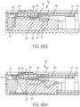
- the actuator button 26 includes two pairs of lockout arms 290, 292 that interact with button contacting surfaces 294, 296 on the needle actuator body 286 prior to device actuation to prevent the needle actuator body 286 from rocking upward. As shown in FIG. 65H , an overlap between the needle actuator body 286 and the housing 20 prevents premature actuation.
- the button spring 284 includes a first bearing surface 298 and a second bearing surface 300 spaced from the first bearing surface 298, and a cantilevered central spring arm 302 surrounded by a pair of outer arms 304 that are joined by the first bearing surface 298.
- the spacer assembly 660 is similar to the spacer assembly 460 discussed above and shown in FIGS. 76-78 and operates in a similar manner to achieve similar advantages.
- the spacer assembly 660 includes a fixed spacer 666 and an adjustable spacer 668.
- the fixed spacer 666 is configured to be received by the stopper 462 with lugs 670 engaging the stopper 462 to secure the fixed spacer 666 within the stopper 462, although other suitable securing arrangements, such as threads, may be utilized.
- the fixed spacer 666 includes interior threads 672 that receive exterior threads 678 of the adjustable spacer 668.
- the spacer assembly 800 has a movable spacer 802 and a fixed spacer holder 804.
- the spacer 802 has a central column 806 and a proximal flange 808.
- the spacer holder 804 is received by the stopper 810 and has a central cavity 812 that receives the central column 806 of the spacer 802.
- the spacer holder 804 may be fixedly attached to the stopper 810 using any suitable method including, but not limited to, adhesive, a threaded connection, and a snap-fit connection.
- the spacer assembly 1500 has a spacer 1502, a spacer holder 1504, and an expandable container 1506.
- the spacer 1502 has a sidewall 1508 extending in a distal direction from a proximal flange 1510.
- the spacer holder 1504 is received by the stopper 1512 and comprises a sidewall 1514 extending in a proximal direction from a bottom portion 1516.
- the sidewall 1514 and the bottom portion 1516 define a central cavity 1518 that receives the sidewall 1508 of the spacer 1502.
- the spacer holder 1504 may be attached to the stopper 1512 using any suitable method including, but not limited to, adhesive, a threaded connection, and a snap-fit connection.
- An opening having a valve 1520 extends through the proximal flange 1510 of the spacer 1502 and into the expandable container 1506.
- the expandable container 1506 may be filled with air or any other suitable fluid via the valve 1520 in order to change the distance that the proximal flange 1510 is separated from the proximal end of the sidewall 1514 of the spacer holder 1504, thereby changing the length of the spacer assembly 1600.
- the distance that the plunger extension 1706 extends beyond the distal end 1714 of the plunger 1702 can be changed by adjusting the length of the plunger extension 1706 that is inserted into the central passageway 1704 of the plunger 1702.
- the plunger assembly 1700 is adjusted by rotating the plunger extension 1706 until the distal end 1716 of the plunger extension 1706 contacts a standard spacer 1718 attached to the stopper 1720. In this manner, the plunger extension 1706 replaces the adjustable spacer assemblies described above while still allowing containers having different fill volumes to be used.
Landscapes
- Health & Medical Sciences (AREA)
- Vascular Medicine (AREA)
- Engineering & Computer Science (AREA)
- Anesthesiology (AREA)
- Biomedical Technology (AREA)
- Heart & Thoracic Surgery (AREA)
- Hematology (AREA)
- Life Sciences & Earth Sciences (AREA)
- Animal Behavior & Ethology (AREA)
- General Health & Medical Sciences (AREA)
- Public Health (AREA)
- Veterinary Medicine (AREA)
- Dermatology (AREA)
- Infusion, Injection, And Reservoir Apparatuses (AREA)
Abstract
Description
- The present application claims priority to
United States Provisional Application Serial No. 62/572,704, filed October 16, 2017 - The present disclosure relates generally to an injector device and method for delivering a fluid into the body of a patient by injection.
- Various types of automatic injection devices have been developed to allow drug solutions and other liquid therapeutic preparations to be administered by untrained personnel or to be self-injected. Generally, these devices include a reservoir that is pre-filled with the liquid therapeutic preparation, and some type of automatic needle-injection mechanism that can be triggered by the user. When the volume of fluid or drug to be administered is generally below a certain volume, such as 1 mL, an auto-injector is typically used, which typically has an injection time of about 10 to 15 seconds. When the volume of fluid or drug to be administered is above 1 mL, the injection time generally becomes longer resulting in difficulties for the patient to maintain contact between the device and the target area of the patient's skin. Further, as the volume of drug to be administered becomes larger, increasing the time period for injection becomes desirable. The traditional method for a drug to be injected slowly into a patient is to initiate an IV and inject the drug into the patient's body slowly. Such a procedure is typically performed in a hospital or outpatient setting.
- Certain devices allow for self-injection in a home setting and are capable of gradually injecting a liquid therapeutic preparation into the skin of a patient. In some cases, these devices are small enough (both in height and in overall size) to allow them to be "worn" by a patient while the liquid therapeutic preparation is being infused into the patient. These devices typically include a pump or other type of discharge mechanism to force the liquid therapeutic preparation to flow out of a reservoir and into the injection needle. Such devices also typically include a valve or flow control mechanism to cause the liquid therapeutic preparation to begin to flow at the proper time and a triggering mechanism to initiate the injection.
- The present invention is directed to a drive assembly for a drug delivery system comprising a plunger member configured to engage and move a stopper within a container, the plunger member having a first position and a second position axially spaced from the first position, a biasing member configured to move the plunger member from the first position to the second position, and an adjustable spacer assembly positioned between the plunger member and the stopper.
- In one aspect, the spacer assembly may comprise a spacer element attached to the stopper and at least one shim.
- In another aspect, the spacer assembly may comprise a spacer element and a holder to which the spacer element is attached. The holder may be attached to the stopper and the spacer element may be attached to the holder by a threaded engagement. The threaded engagement may allow rotation of the spacer element relative to the holder when a torque is applied to the spacer element to prohibit rotation of the spacer element relative to the holder when an axial force is applied to the spacer element. The threads provided on the spacer element may extend in a radially outward direction. The threads provided on the spacer element may be angled such that application of an axial force to the spacer element causes the threads to engage a sidewall of the holder.
- When the spacer element is in a first position with respect to the holder, the spacer assembly has a first length in a longitudinal direction, and when the when the spacer element is in a second position with respect to the holder, the spacer assembly has a second length in the longitudinal direction, the first length being greater than the second length.
- In another aspect, the spacer assembly may further comprise a flexible tab extending from the spacer element and a plurality of ratchet teeth on a surface of the spacer holder. The flexible tab engages the ratchet teeth and the engagement of the flexible tab with the ratchet teeth allows the spacer element to be rotated in a direction that threads the spacer element into the holder and prevents the spacer element from rotating in a direction that removes the spacer element from the holder.
- In another aspect, the spacer element is in a first position with respect to the holder, the spacer assembly has a first length in a longitudinal direction, and when the when the spacer element is in a second position with respect to the holder, the spacer assembly has a second length in the longitudinal direction, the first length being greater than the second length.
- In another aspect, the spacer element may comprise a first protrusion and the holder may comprise a second protrusion. When the spacer element is in the first position with respect to the holder, the first protrusion is in contact with the second protrusion and the spacer assembly has the first length in the longitudinal direction, and when the spacer element is in a second position with respect to the holder, the first protrusion is not in contact with the second protrusion and the spacer assembly has the second length in the longitudinal direction.
- In another aspect, the spacer element may comprise an annular sidewall and the holder may comprise a sidewall and a central post. An exterior surface of the annular sidewall of the spacer element may be in threaded engagement with an interior surface of the sidewall of the holder and an interior surface of the sidewall of the spacer may be in threaded engagement with an exterior surface of the central post. When the central post is a first position, movement of the spacer element with respect to the holder is prohibited, and when the central post is axially extended to a second position, the spacer element is free to rotate with respect to the holder.
- In another aspect, the spacer assembly may further comprise a locking pin and the spacer element may further comprise a recess for receiving the locking pin.
- In another aspect, the spacer assembly may further comprise an expandable container positioned within the spacer element and the holder between an upper proximal portion of the spacer element and a lower bottom portion of the holder. Expansion or contraction of the expandable container may cause the spacer element to move relative to the holder.
- In another aspect, the spacer assembly may comprise a spacer element fixed to the stopper and a plunger extension movably fixed to the plunger member. The plunger extension may be in threaded engagement with the plunger member.
- The present invention is also directed to a drug delivery system for injecting a medicament, the system comprising a container configured to receive a medicament, the container comprising a stopper configured to move within the container and a closure, a drive assembly as described above, and a needle actuator assembly comprising a needle configured to be placed in fluid communication with the container.
- The above-mentioned and other features and advantages of this disclosure, and the manner of attaining them, will become more apparent and the disclosure itself will be better understood by reference to the following descriptions of embodiments of the disclosure taken in conjunction with the accompanying drawings, wherein:
-
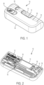
FIG. 1 is a perspective view of a drug delivery system according to one aspect of the present invention. -
FIG. 2 is a perspective, cross-sectional view of the drug delivery system ofFIG. 1 according to one aspect of the present invention. -
FIG. 3 is a front, cross-sectional view of the drug delivery system ofFIG. 1 according to one aspect of the present invention. -
FIG. 4 is a top view of the drug delivery system ofFIG. 1 according to one aspect of the present invention, showing a top portion of the housing removed and the drug delivery system in a pre-use position. -
FIG. 5 is a top, cross-sectional view of the drug delivery system ofFIG. 1 according to one aspect of the present invention, showing the drug delivery system in a pre-use position. -
FIG. 6 is a front, cross-sectional view of the drug delivery system ofFIG. 1 according to one aspect of the present invention, showing the drug delivery system in a pre-use position. -
FIG. 7 is a top view of the drug delivery system ofFIG. 1 according to one aspect of the present invention, showing a top portion of the housing removed and the drug delivery system in an initial actuation position. -
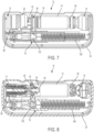
FIG. 8 is a top, cross-sectional view of the drug delivery system ofFIG. 1 according to one aspect of the present invention, showing the drug delivery system in an initial actuation position. -
FIG. 9 is a front, cross-sectional view of the drug delivery system ofFIG. 1 according to one aspect of the present invention, showing the drug delivery system in an initial actuation position. -
FIG. 10 is a top view of the drug delivery system ofFIG. 1 according to one aspect of the present invention, showing a top portion of the housing removed and the drug delivery system in a use position. -
FIG. 11 is a top, cross-sectional view of the drug delivery system ofFIG. 1 according to one aspect of the present invention, showing the drug delivery system in a use position. -
FIG. 12 is a front, cross-sectional view of the drug delivery system ofFIG. 1 according to one aspect of the present invention, showing the drug delivery system in a use position. -
FIG. 13 is a top view of the drug delivery system ofFIG. 1 according to one aspect of the present invention, showing a top portion of the housing removed and the drug delivery system in a post-use position. -
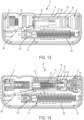
FIG. 14 is a top, cross-sectional view of the drug delivery system ofFIG. 1 according to one aspect of the present invention, showing the drug delivery system in a post-use position. -
FIG. 15 is a front, cross-sectional view of the drug delivery system ofFIG. 1 according to one aspect of the present invention, showing the drug delivery system in a post-use position. -
FIG. 15A is a front, cross-sectional view of the drug delivery system ofFIG. 1 according to one aspect of the present invention, showing a pad with the drug delivery system in a pre-use position. -
FIG. 15B is a perspective, cross-sectional view of the drug delivery system ofFIG. 1 according to one aspect of the present invention, showing a pad with the drug delivery system in a pre-use position. -
FIG. 15C is a perspective, cross-sectional view of the drug delivery system ofFIG. 1 according to one aspect of the present invention, showing a pad with the drug delivery system in a pre-use position. -
FIG. 16 is a partial cross-sectional view of the drug delivery system ofFIG. 1 according to one aspect of the present invention, showing a valve assembly. -
FIG. 17 is a perspective view of a drive assembly for a drug delivery system according to one aspect of the present invention. -
FIG. 18 is a cross-sectional view of the drive assembly ofFIG. 17 according to one aspect of the present invention, showing a pre-use position of the drive assembly. -
FIG. 19 is a cross-sectional view of the drive assembly ofFIG. 17 according to one aspect of the present invention, showing a use position of the drive assembly. -
FIG. 20 is a cross-sectional view of the drive assembly ofFIG. 17 according to one aspect of the present invention, showing a post-use position of the drive assembly. -
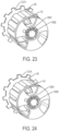
FIG. 21 is a perspective view of a plunger actuation member of the drive assembly ofFIG. 17 according to one aspect of the present invention. -
FIG. 22 is a perspective view of a first plunger member of the drive assembly ofFIG. 17 according to one aspect of the present invention. -
FIG. 23 is a perspective view of a plunger actuation member and first plunger member of the drive assembly ofFIG. 17 according to one aspect of the present invention, showing the plunger actuation member engaged with the first plunger member. -
FIG. 24 is a perspective view of a plunger actuation member and first plunger member of the drive assembly ofFIG. 17 according to one aspect of the present invention, showing the plunger actuation member disengaged from the first plunger member. -
FIG. 25 is a perspective view of a plunger actuation member and first plunger member of the drive assembly ofFIG. 17 according to one aspect of the present invention, showing the plunger actuation member disengaged from and axially displaced relative to the first plunger member. -
FIG. 26 is a front view of a first plunger member and a second plunger member of the drive assembly ofFIG. 17 according to one aspect of the present invention. -
FIG. 27 is a top view of a drive assembly for a drug delivery system according to a further aspect of the present invention. -
FIG. 28 is a perspective view of the drive assembly ofFIG. 27 according to one aspect of the present invention. -
FIG. 29 is a cross-sectional view of the drive assembly ofFIG. 27 according to one aspect of the present invention, showing a pre-use position of the drive assembly. -
FIG. 30 is a perspective view of the drive assembly ofFIG. 27 according to one aspect of the present invention, showing the drive assembly received by a bottom portion of a housing. -
FIG. 31 is a perspective view of the housing ofFIG. 30 according to one aspect of the present invention. -
FIG. 32 is a top view of the drive assembly ofFIG. 27 according to one aspect of the present invention, showing engagement of the drive assembly with a portion of a needle actuator in an initial actuation position of the drive assembly. -
FIG. 33 is an enlarged perspective view of the drive assembly ofFIG. 27 according to one aspect of the present invention, showing engagement of the drive assembly with a portion of a needle actuator in an initial actuation position of the drive assembly. -
FIG. 34 is a front view of a needle actuator assembly according to one aspect of the present invention. -
FIG. 35 is a left side perspective view of a needle shuttle of the needle actuator assembly ofFIG. 34 according to one aspect of the present invention. -
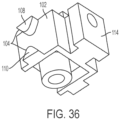
FIG. 36 is a right side perspective view of a needle shuttle of the needle actuator assembly ofFIG. 34 according to one aspect of the present invention. -
FIG. 37A is a front view of the needle actuator assembly ofFIG. 34 according to one aspect of the present invention, showing the needle actuator assembly in a pre-use position. -
FIG. 37B is a front view of the needle actuator assembly ofFIG. 34 according to one aspect of the present invention, showing the needle actuator assembly in a use position. -
FIG. 37C is a front view of the needle actuator assembly ofFIG. 34 according to one aspect of the present invention, showing the needle actuator assembly in an initial post-use position. -
FIG. 37D is a front view of the needle actuator assembly ofFIG. 34 according to one aspect of the present invention, showing the needle actuator assembly in a post-use position. -
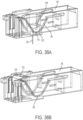
FIG. 38A is a perspective view of the needle actuator assembly ofFIG. 34 according to one aspect of the present invention, showing the needle actuator assembly in a use position. -
FIG. 38B is a perspective view of the needle actuator assembly ofFIG. 34 according to one aspect of the present invention, showing the needle actuator assembly in an initial post-use position. -
FIG. 39 is a perspective view of an actuator button and the needle actuator assembly ofFIG. 34 according to one aspect of the present invention, showing the needle actuator assembly in an initial post-use position. -
FIG. 40A is a cross-sectional view of an actuator button and the needle actuator assembly ofFIG. 34 according to one aspect of the present invention, showing the needle actuator assembly in an initial post-use position. -
FIG. 40B is a perspective view of an actuator button and the needle actuator assembly ofFIG. 34 according to one aspect of the present invention, showing the needle actuator assembly in a post-use position. -
FIG. 41 is a perspective view of a drive assembly for a drug delivery system according to a further aspect of the present invention. -
FIG. 42 is a perspective view of the drive assembly ofFIG. 41 according to one aspect of the present invention, showing a top portion of a housing removed. -
FIG. 43 is a cross-sectional view of the drive assembly ofFIG. 41 according to one aspect of the present invention. -
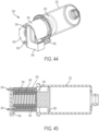
FIG. 44 is a perspective view of the drive assembly ofFIG. 41 according to one aspect of the present invention. -
FIG. 45 is a cross-sectional view of the drive assembly ofFIG. 41 according to one aspect of the present invention, showing the drive assembly in a pre-use position. -
FIG. 46 is a cross-sectional view of the drive assembly ofFIG. 41 according to one aspect of the present invention, showing the drive assembly in a pre-use position. -
FIG. 47 is a top view of the drive assembly ofFIG. 41 according to one aspect of the present invention, showing the drive assembly in a pre-use position. -
FIG. 48 is a top view of the drive assembly ofFIG. 41 according to one aspect of the present invention, showing the drive assembly in an initial actuation position. -
FIG. 49 is a top view of the drive assembly ofFIG. 41 according to one aspect of the present invention, showing the drive assembly in an initial actuation position. -
FIG. 50 is a top view of the drive assembly ofFIG. 41 according to one aspect of the present invention, showing the drive assembly an initial actuation position. -
FIG. 51 is a top view of the drive assembly ofFIG. 41 according to one aspect of the present invention, showing the drive assembly in a use position. -
FIG. 52 is a top view of the drive assembly ofFIG. 41 according to one aspect of the present invention, showing the drive assembly in a use position. -
FIG. 53 is a cross-sectional view of the drive assembly ofFIG. 41 according to one aspect of the present invention, showing the drive assembly in a use position. -
FIG. 54 is a top view of the drive assembly ofFIG. 41 according to one aspect of the present invention, showing the drive assembly in a use position. -
FIG. 55 is a cross-sectional view of the drive assembly ofFIG. 41 according to one aspect of the present invention, showing the drive assembly in a use position. -
FIG. 56 is a cross-sectional view of the drive assembly ofFIG. 41 according to one aspect of the present invention, showing the drive assembly in a use position. -
FIG. 57 is a top view of the drive assembly ofFIG. 41 according to one aspect of the present invention, showing the drive assembly in a use position. -
FIG. 58 is a top view of the drive assembly ofFIG. 41 according to one aspect of the present invention, showing the drive assembly in an initial post-use position. -
FIG. 59 is a perspective view of the drive assembly ofFIG. 41 according to one aspect of the present invention, showing the drive assembly in an initial post-use position. -
FIG. 60 is a top view of the drive assembly ofFIG. 41 according to one aspect of the present invention, showing the drive assembly in a post-use position. -
FIG. 61 top view of the drive assembly ofFIG. 41 according to one aspect of the present invention, showing the drive assembly in a post-use position. -
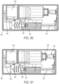
FIG. 62 is a cross-sectional view of the drive assembly ofFIG. 41 according to one aspect of the present invention, showing the drive assembly in a pre-use position. -
FIG. 63 is a cross-sectional view of the drive assembly ofFIG. 41 according to one aspect of the present invention, showing the drive assembly in a use position. -
FIG. 64 is a perspective view of a drive assembly according to a further aspect of the present invention. -
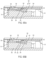
FIG. 65A is a front view of a needle actuator assembly according to one aspect of the present invention, showing the needle actuator assembly in a use position. -
FIG. 65B is a front view of the needle actuator assembly ofFIG. 65A according to one aspect of the present invention, showing the needle actuator assembly in a use position. -
FIG. 65C is a front view of the needle actuator assembly ofFIG. 65A according to one aspect of the present invention, showing the needle actuator assembly in an initial post-use position. -
FIG. 65D is a front view of the needle actuator assembly ofFIG. 65A according to one aspect of the present invention, showing the needle actuator assembly in a post-use position. -
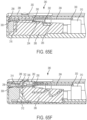
FIG. 65E is a front view of the needle actuator assembly ofFIG. 65A according to one aspect of the present invention, showing the needle actuator assembly in a pre-use position. -
FIG. 65F is a cross-sectional view of the needle actuator assembly ofFIG. 65A according to one aspect of the present invention, showing the needle actuator assembly in a pre-use position. -
FIG. 65G is a front view of the needle actuator assembly ofFIG. 65A according to one aspect of the present invention, showing the needle actuator assembly in a pre-use position with a button actuator axially displaced. -
FIG. 65H is a cross-sectional view of the needle actuator assembly ofFIG. 65A according to one aspect of the present invention, showing the needle actuator assembly in a pre-use position with a button actuator axially displaced. -
FIG. 66 is a perspective view of a button spring of the needle actuator assembly ofFIG. 65A according to one aspect of the present invention. -
FIG. 67 is a perspective view of an actuator button of the needle actuator assembly ofFIG. 65A according to one aspect of the present invention. -
FIG. 68 is a cross-sectional view of a button spring and actuator button of the needle actuator assembly ofFIGS. 65A according to one aspect of the present invention. -
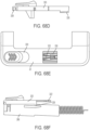
FIG. 68A is a perspective view of an actuator button of the needle actuator assembly ofFIG. 65A according to a further aspect of the present invention. -
FIG. 68B is a bottom view of an actuator button of the needle actuator assembly ofFIG. 65A according to a further aspect of the present invention. -
FIG. 68C is a front view of an actuator button of the needle actuator assembly ofFIG. 65A according to a further aspect of the present invention. -
FIG. 68D is a top view of an actuator button of the needle actuator assembly ofFIG. 65A according to a further aspect of the present invention, showing the actuator button in a pre-use position. -
FIG. 68E is a front view of an actuator button of the needle actuator assembly ofFIG. 65A according to a further aspect of the present invention, showing the actuator button in a pre-use position. -
FIG. 68F is a top view of an actuator button of the needle actuator assembly ofFIG. 65A according to a further aspect of the present invention, showing the actuator button in a use position. -
FIG. 68G is a front view of an actuator button of the needle actuator assembly ofFIG. 65A according to a further aspect of the present invention, showing the actuator button in a use position. -
FIG. 69 is a top view of an actuator button of the needle actuator assembly ofFIG. 65A according to one aspect of the present invention. -
FIG. 70 is a perspective view of a restriction member according to one aspect of the present invention. -
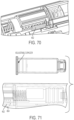
FIG. 71 is a front view of a spacer assembly for a drug delivery system according to a further aspect of the present invention. -
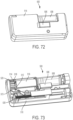
FIG. 72 is a perspective view of a drive assembly for a drug delivery system according to one aspect of the present invention. -
FIG. 73 is a perspective view of the drive assembly ofFIG. 72 according to one aspect of the present invention, showing a top portion of a housing removed. -
FIG. 74 is a cross-sectional view of the drive assembly ofFIG. 72 according to one aspect of the present invention, showing a pre-use position of the drive assembly. -
FIG. 75 is an enlarged cross-sectional view of the drive assembly ofFIG. 72 according to one aspect of the present invention, showing a pre-use position of the drive assembly. -
FIG. 76 is a top view of a biasing member of the drive assembly ofFIG. 72 according to one aspect of the present invention. -
FIG. 77 is a perspective view of the drive assembly ofFIG. 72 according to one aspect of the present invention, showing a restriction member engaged with the drive assembly. -
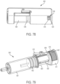
FIG. 78 is a perspective view of a drive assembly for a drug delivery system according to one aspect of the present invention. -
FIG. 79 is a perspective view of the drive assembly ofFIG. 78 according to one aspect of the present invention, showing a pre-use position of the drive assembly. -
FIG. 80 is a cross-sectional view of the drive assembly ofFIG. 78 according to one aspect of the present invention. -
FIG. 81 is a perspective view of the drive assembly ofFIG. 78 according to one aspect of the present invention, showing a post-use position of the drive assembly. -
FIG. 82 is a cross-sectional view of the drive assembly ofFIG. 78 according to one aspect of the present invention, showing a pre-use position of the drive assembly. -
FIG. 83 is a front view of the drive assembly ofFIG. 78 according to one aspect of the present invention, showing a use position of the drive assembly. -
FIG. 84A is a schematic view of a drive assembly according to one aspect of the present invention, showing the drive assembly in a pre-use position. -
FIG. 84B is a schematic view of the drive assembly ofFIG. 84A according to one aspect of the present invention, showing the drive assembly in a use position. -
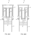
FIG. 84C is a schematic view of the drive assembly ofFIG. 84A according to one aspect of the present invention, showing the drive assembly in a use position. -
FIG. 84D is a schematic view of the drive assembly ofFIG. 84A according to one aspect of the present invention, showing the drive assembly in a use position. -
FIG. 84E is a schematic view of the drive assembly ofFIG. 84A according to one aspect of the present invention, showing the drive assembly in a use position. -
FIG. 84F is a schematic view of the drive assembly ofFIG. 84A according to one aspect of the present invention, showing the drive assembly in a post-use position. -
FIG. 84G is a schematic view of the drive assembly ofFIG. 84A according to one aspect of the present invention, showing the drive assembly in a post-use position. -
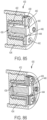
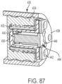
FIG. 85 is a perspective view of a spacer assembly for a drug delivery system according to one aspect of the present invention, showing an assembled, pre-use position of the spacer assembly. -
FIG. 86 is a perspective view of the spacer assembly ofFIG. 85 according to one aspect of the present invention, showing a use position of the spacer assembly. -
FIG. 87 is a perspective view of the spacer assembly ofFIG. 85 according to one aspect of the present invention, showing an initial post-use position of the spacer assembly. -
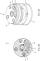
FIG. 88 is a top view of a spacer assembly for a drug delivery system according to one aspect of the present invention. -
FIG. 89 is a perspective view of the spacer assembly ofFIG. 88 according to one aspect of the present invention. -
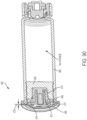
FIG. 90 is a cross-sectional view of the spacer assembly ofFIG. 88 according to one aspect of the present invention. -
FIG. 91 is a perspective view of a spacer assembly for a drug delivery system according to a further aspect of the present invention. -
FIG. 92 is a perspective view of a spacer assembly for a drug delivery system according to another aspect of the present invention. -
FIG. 93A is a cross-sectional view of the spacer assembly ofFIG. 92 according to one aspect of the present invention, showing a pre-assembly position of the spacer assembly. -
FIG. 93B is a cross-sectional view of the spacer assembly ofFIG. 92 according to one aspect of the present invention, showing an assembled position of the spacer assembly. -
FIG. 94 is a perspective view of a spacer assembly for a drug delivery system according to one aspect of the present invention. -
FIG. 95 is a front view of the spacer assembly ofFIG. 94 according to one aspect of the present invention. -
FIG. 96 is a cross-sectional view of the spacer assembly ofFIG. 94 according to one aspect of the present invention. -
FIG. 97 is a perspective view of the spacer assembly ofFIG. 94 according to one aspect of the present invention, showing a shim removed. -
FIG. 98 is a perspective view of a fixed spacer of the spacer assembly ofFIG. 94 according to one aspect of the present invention. -
FIG. 99 is a perspective view of an adjustable spacer of the spacer assembly ofFIG. 94 according to one aspect of the present invention. -
FIG. 100 is a perspective view of a shim of the spacer assembly ofFIG. 94 according to one aspect of the present invention. -
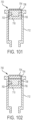
FIG. 101 is a cross-sectional view of a spacer assembly having a single shim according to one aspect of the present invention. -
FIG. 102 is a cross-sectional view of the spacer assembly ofFIG. 101 having multiple shims according to one aspect of the present invention. -
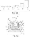
FIG. 103 is a cross-sectional view a set of shims for use with the spacer assembly ofFIG. 101 according to one aspect of the present invention. -
FIG. 104 is a cross-sectional view of a spacer assembly according to one aspect of the present invention. -
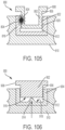
FIG. 105 is a cross-sectional view of a spacer assembly according to one aspect of the present invention. -
FIG. 106 is a cross-sectional view of a spacer assembly according to one aspect of the present invention. -
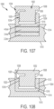
FIG. 107 is a cross-sectional view of a spacer assembly according to one aspect of the present invention. -
FIG. 108 is a cross-sectional view of a spacer assembly according to one aspect of the present invention. -
FIG. 109 is a cross-sectional view of a spacer assembly shown in a first position according to one aspect of the present invention. -
FIG. 110 is a cross-sectional view of the spacer assembly ofFIG. 109 shown in a second position according to one aspect of the present invention. -
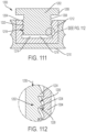
FIG. 111 is a cross-sectional view of a spacer assembly according to one aspect of the present invention. -
FIG. 112 is a magnified cross-sectional view of the indicated portion of the spacer assembly ofFIG. 111 according to one aspect of the present invention. -
FIG. 113 is a cross-sectional view of a spacer assembly shown in a first position according to one aspect of the present invention. -
FIG. 114 is a cross-sectional view of the spacer assembly ofFIG. 113 shown in a second position according to one aspect of the present invention. -
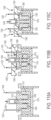
FIG. 115A is a cross-sectional view of a first step in the assembly of the spacer assembly ofFIG. 113 according to one aspect of the present invention. -
FIG. 115B is a cross-sectional view of a second step in the assembly of the spacer assembly ofFIG. 113 according to one aspect of the present invention. -
FIG. 115C is a cross-sectional view of a first step in the assembly of the spacer assembly ofFIG. 113 according to one aspect of the present invention. -
FIG. 116 is a cross-sectional view of a spacer assembly before the insertion of the locking pin according to one aspect of the present invention. -
FIG. 117 is a cross-sectional view of a spacer assembly ofFIG. 116 after the insertion of the locking pin according to one aspect of the present invention. -
FIG. 118 is a cross-sectional view of a spacer assembly according to one aspect of the present invention. -
FIG. 119 is a cross-sectional view of an adjustable plunger assembly according to one aspect of the present invention. - The exemplifications set out herein illustrate exemplary aspects of the disclosure, and such exemplifications are not to be construed as limiting the scope of the disclosure in any manner.
- The following description is provided to enable those skilled in the art to make and use the described embodiments contemplated for carrying out the invention. Various modifications, equivalents, variations, and alternatives, however, will remain readily apparent to those skilled in the art. Any and all such modifications, variations, equivalents, and alternatives are intended to fall within the spirit and scope of the present invention.
- For purposes of the description hereinafter, the terms "upper", "lower", "right", "left", "vertical", "horizontal", "top", "bottom", "lateral", "longitudinal", and derivatives thereof shall relate to the invention as it is oriented in the drawing figures. However, it is to be understood that the invention may assume various alternative variations, except where expressly specified to the contrary. It is also to be understood that the specific devices illustrated in the attached drawings, and described in the following specification, are simply exemplary embodiments of the invention. Hence, specific dimensions and other physical characteristics related to the embodiments disclosed herein are not to be considered as limiting.
- Referring to
FIGS. 1-16 , adrug delivery system 10 according to one aspect of the present invention includes adrive assembly 12, acontainer 14, avalve assembly 16, and aneedle actuator assembly 18. Thedrive assembly 12, thecontainer 14, thevalve assembly 16, and theneedle actuator assembly 18 are at least partially positioned within ahousing 20. Thehousing 20 includes atop portion 22 and abottom portion 24, although other suitable arrangements for thehousing 20 may be utilized. In one aspect, thedrug delivery system 10 is an injector device configured to be worn or secured to a user and to deliver a predetermined dose of a medicament provided within thecontainer 14 via injection into the user. Thesystem 10 may be utilized to deliver a "bolus injection" where a medicament is delivered within a set time period. The medicament may be delivered over a time period of up to 45 minutes, although other suitable injection amounts and durations may be utilized. A bolus administration or delivery can be carried out with rate controlling or have no specific rate controlling. Thesystem 10 may deliver the medicament at a fixed pressure to the user with the rate being variable. The general operation of thesystem 10 is described below in reference toFIGS. 1-16 with the specifics of thedrive assembly 12,needle actuator assembly 18, and other features of thesystem 10, discussed below in connection withFIGS. 17-93 . - Referring again to
FIGS. 1-16 , thesystem 10 is configured to operate through the engagement of anactuation button 26 by a user, which results in aneedle 28 of theneedle assembly 18 piercing the skin of a user, the actuation of thedrive assembly 12 to place theneedle 28 in fluid communication with thecontainer 14 and to expel fluid or medicament from thecontainer 14, and the withdrawal of theneedle 28 after injection of the medicament is complete. The general operation of a drug delivery system is shown and described in International Publication Nos.2013/155153 and2014/179774 , which are hereby incorporated by reference in their entirety. Thehousing 20 of thesystem 10 includes anindicator window 30 for viewing anindicator arrangement 32 configured to provide an indication to a user on the status of thesystem 10 and acontainer window 31 for viewing thecontainer 14. Theindicator window 30 may be a magnifying lens for providing a clear view of theindicator arrangement 32. Theindicator arrangement 32 moves along with theneedle actuator assembly 18 during use of thesystem 10 to indicate a pre-use status, use status, and post-use status of thesystem 10. Theindicator arrangement 32 provides visual indicia regarding the status, although other suitable indicia, such an auditory or tactile, may be provided as an alternative or additional indicia. - Referring to
FIGS. 4-6 , during a pre-use position of thesystem 10, thecontainer 14 is spaced from thedrive assembly 12 and thevalve assembly 16 and theneedle 28 is in a retracted position. During the initial actuation of thesystem 10, as shown inFIGS. 7-9 , thedrive assembly 12 engages thecontainer 14 to move thecontainer 14 toward thevalve assembly 16, which is configured to pierce aclosure 36 of thecontainer 14 and place the medicament within thecontainer 14 in fluid communication with theneedle 28 via a tube (not shown) or other suitable arrangement. Thedrive assembly 12 is configured to engage astopper 34 of thecontainer 14, which will initially move theentire container 14 into engagement with thevalve assembly 16 due to the incompressibility of the fluid or medicament within thecontainer 14. The initial actuation of thesystem 10 is caused by engagement of theactuation button 26 by a user, which releases theneedle actuator assembly 18 and thedrive assembly 12 as discussed below in more detail. During the initial actuation, theneedle 28 is still in the retracted position and about to move to the extended position to inject the user of thesystem 10. - In the use position of the
system 10, as shown inFIGS. 10-12 , theneedle 28 is in the extended position at least partially outside of thehousing 20 with thedrive assembly 12 moving thestopper 34 within thecontainer 14 to deliver the medicament from thecontainer 14, through theneedle 28, and to the user. In the use position, thevalve assembly 16 has already pierced aclosure 36 of thecontainer 14 to place thecontainer 14 in fluid communication with theneedle 28, which also allows thedrive assembly 12 to move thestopper 34 relative to thecontainer 14 since fluid is able to be dispensed from thecontainer 14. At the post-use position of thesystem 10, shown inFIGS. 13-15 , theneedle 28 is in the retracted position and engaged with apad 38 to seal theneedle 28 and prevent any residual flow of fluid or medicament from thecontainer 14. Thecontainer 14 andvalve assembly 16 may be thecontainer 14 andvalve assembly 16 shown and described in International Publication No.WO 2015/081337 , which is hereby incorporated by reference in its entirety. - Referring to
FIGS. 15A-15C , thepad 38 is biased into the pad as theneedle actuator body 96 moves from the use position to the post-use position. In particular, thepad 38 is received by apad arm 122 having acam surface 124 that cooperates with acam track 126 on thebottom portion 24 of thehousing 20. Thepad arm 122 is connected to theneedle actuator body 96 via atorsion bar 128. Thecam surface 124 is configured to engage thecam track 126 to deflect thepad arm 122 downwards thereby allowing thepad 38 to pass beneath theneedle 28 before being biased upwards into theneedle 28. Thetorsion bar 128 allows thepad arm 122 to twist about a pivot of theneedle actuator body 96. Thepad 38 may be press-fit into an opening of thepad arm 122, although other suitable arrangements for securing thepad 38 may be utilized. - Referring to
FIGS. 1-33 , thedrive assembly 12 according to one aspect of the present invention is shown. As discussed above, thedrive assembly 12 is configured to move thecontainer 14 to pierce theclosure 36 of thecontainer 14 and also to move thestopper 34 within thecontainer 14 to dispense fluid or medicament from thecontainer 14. - For manufacturing purposes, using one size for a
medicament container 14 is often desirable, even if multiple fill volumes or dosages are contemplated for use with thecontainer 14. In such cases, when medicament containers are filled, the differing fill volumes result in different positions of thestopper 34. To accommodate suchdifferent stopper 34 positions, as well as accommodate manufacturing differences of thestoppers 34, aspects of the present invention include a bespoke or custom spacer orspacer assembly 40 disposed in a proximal end of thecontainer 14, proximal to thestopper 34. The custom spacer orspacer assembly 40 is selected from a plurality of different size spacers orspacer assemblies 40 to occupy space from a proximal end of thestopper 34 to a proximal end of thecontainer 14. In other words, the custom spacer orspacer assembly 40 provides an option that allows dispensing of a range of manufacturer-set pre-defined fill volumes by selection of different spacers orspacer assemblies 40, and reduces or eliminates the need for assembly configuration operations. The size of the custom spacer orspacer assembly 40 can be employed to account for under-filled volumes of thecontainer 14, and provide a consistent bearing surface at the proximal end of thecontainer 14. - The
drive assembly 12 shown inFIGS. 17-33 is configured to engage and cooperate with aspacer assembly 40 received by thestopper 34 of thecontainer 14. Thespacer assembly 40 includes aspacer 42 and aspacer holder 44. Thespacer holder 44 is received by thestopper 34 and thespacer 42 is received by thespacer holder 44. Thespacer holder 44 includes a first threaded portion 46 that engages a corresponding threaded portion of thestopper 34, although other suitable arrangements may be utilized. Thespacer 42 also includes a threaded portion 48 that engages a corresponding second threaded portion 50 of thespacer holder 44 for securing thespacer 42 to thespacer holder 44, although other suitable arrangements may be utilized. Thedrive assembly 12 is configured to dispense a range of pre-determined fill volumes of thecontainer 14 while maintaining the functional features of thesystem 10 described above, including, but not limited to, retraction of theneedle 28 after the end of the dose and providing an indication of the status of thesystem 10 while also minimizing abrupt engagement of thestopper 34 by thedrive assembly 12. A discussed above, thedrive assembly 12 is configured to dispense a plurality of discrete fill volume ranges by utilizing a plurality of sizes of thespacers 42. In one aspect, twelve fill volume ranges and twelvespacer 42 sizes are provided. - Referring to
FIGS. 17-26 , thedrive assembly 12 includes afirst plunger member 52, asecond plunger member 54 received by thefirst plunger member 52, a first biasingmember 56, asecond biasing member 58, aplunger actuation member 60, and anindex member 62. Thefirst plunger member 52 is moveable from a pre-use position (shown inFIG. 18 ), to a use position (shown inFIG. 19 ), to a post-use position (shown inFIG. 20 ) with thefirst plunger member 52 configured to engage thespacer assembly 40 and move thestopper 34 within thecontainer 14 to dispense medicament from thecontainer 14. Thefirst plunger member 52 is configured to move axially. Thesecond plunger member 54 and thefirst plunger member 52 form a telescoping arrangement with thesecond plunger 54 configured to move axially after thefirst plunger member 52 moves a predetermined axial distance. The movement of the first andsecond plunger members second biasing members members - The
first biasing member 56 is received by thesecond plunger member 54 and is constrained between the plunger actuation member 60 (and index member 62) and afirst spring seat 64 of thesecond plunger member 54. Thesecond biasing member 58 is positioned radially inward from the first biasingmember 56 and received by thesecond plunger member 54. Thesecond biasing member 58 is constrained between asecond spring seat 66 of thesecond plunger member 54 and thefirst plunger member 52. Thesecond biasing member 58 is configured to bias thefirst plunger 52 member towards thecontainer 14 from the pre-use position, to the use position, and to the post-use position. Thefirst biasing member 56 is configured to bias thesecond plunger member 54 towards thecontainer 14, which, in turn, biases thefirst plunger member 52 towards thecontainer 14 from the pre-use position, to the use position, and to the post-use position. More specifically, the second biasingmember 58 is configured to drive thefirst plunger member 52 against thespacer assembly 40 orstopper 34 to move thecontainer 14 into engagement thevalve assembly 16 thereby piercing theclosure 36 of thecontainer 14 and placing thecontainer 14 in fluid communication with theneedle 28. Thefirst biasing member 56 is configured to move thestopper 34 within thecontainer 14 to dispense the medicament within thecontainer 14. Thesecond biasing member 58 has a different spring constant than the first biasingmember 56. In particular, the second biasing 58 member is stiffer than the first biasingmember 56 to provide a high force for piercing theclosure 36 of thecontainer 14 while the first biasingmember 56 provides a lower force for dispensing as appropriate for the viscosity of the fluid or medicament within thecontainer 14. - Referring again to
FIGS. 17-26 , theplunger actuation member 60 has anannular portion 68 and aspindle portion 70. Theplunger actuation member 60 is rotationally moveable relative to thefirst plunger member 52 between a first rotational position and a second rotational position spaced from the first rotational position. The first rotational position may be 15 degrees from the second rotational position, although other suitable positions may be utilized. Theannular portion 68 includes adrive surface 72 including a plurality ofgears 74, although other suitable arrangements may be utilized for thedrive surface 72. Thespindle portion 70 includes anactuator locking surface 76 configured for engagement and release from a plunger locking surface 78 of thefirst plunger member 52. The plunger locking surface 78 includes a plurality of projections 80 configured to be received by a plurality of slots or cutouts 81 defined by theactuator locking surface 76. - As shown in
FIGS. 18 and23 , in the first rotational position of theplunger actuation member 60, the plurality of projections 80 and the plurality of slots or cutouts 81 are out of alignment such that the plunger actuation member 80 is engaged with thefirst plunger member 52 to prevent movement of the first andsecond plunger members second biasing members second plunger members plunger actuation member 60. As shown inFIGS. 19 and24 , in the second rotational position of theplunger actuation member 60, the plurality of projections 80 and the plurality of slots or cutouts 81 are aligned with each other such that theplunger actuation member 60 is disengaged with thefirst plunger member 52 to allow movement of the first andsecond plunger members container 14. - Referring to
FIGS. 7 and33 , thedrive surface 72 of theplunger actuation member 60 is configured to be engaged by a portion of theneedle actuator assembly 18. After engagement of theactuator button 26 and release of theneedle actuator assembly 18, which is discussed in more detail below, theneedle actuator assembly 18 moves within thehousing 20 from the pre-use position, to the use position, and to the post-use position. During the initial movement of theneedle actuator assembly 18, a portion of theneedle actuator assembly 18 engages thedrive surface 72 of theplunger actuation member 60 to move theplunger actuation member 60 from the first rotational position to the second rotational position. As shown inFIG. 33 , anangled blade portion 82 of theneedle actuator assembly 18 engages thedrive surface 72 of theplunger actuation member 60 to cause rotation of theplunger actuation member 60. - Referring to
FIGS. 11 ,13 , and26 , thesecond plunger member 52 includes a plurality of codedprojections 84 with a preselected one of the plurality of codedprojections 84 configured to engage arestriction member 86 of thesystem 10. As discussed in more detail below, therestriction member 86 cooperates with theneedle actuation assembly 18 and restricts movement of theneedle actuator assembly 18 from the use position to the post-use position until a predetermined end-of-dose position of thestopper 34 is reached. In one aspect, therestriction member 86 is configured to restrict axial movement of theneedle actuation assembly 18 from the use position through engagement between therestriction member 86 and a portion of theneedle actuation assembly 18. Such engagement between therestriction member 86 and theneedle actuation assembly 18 is released by rotation of therestriction member 86 when thestopper 34 reaches the end-of-dose position. During the use position of theneedle actuator assembly 18, therestriction member 86 is biased in a rotational direction with the rotation of therestriction member 86 being prevented through engagement between therestriction member 86 and one of the plurality of codedprojections 84 of thesecond plunger member 54. The plurality of codedprojections 84 may be axial ribs of varying length, although other suitable arrangements may be utilized. Each codedprojection 84 defines a point at which therestriction member 86 is able to rotate thereby releasing theneedle actuator assembly 18. The smooth portion of thesecond plunger member 52 may also provide a further "code" for determining when thesystem 10 transitions to the end-of-dose position. - As discussed above, the
indicator arrangement 32 moves with different portions of theindicator arrangement 32 visible through theindicator window 30 as thesystem 10 moves from the pre-use, use, and post-use or end-of-dose positions. More specifically, theindicator arrangement 32 engages a portion of therestriction member 86 and moves along with therestriction member 86 through the various stages of thesystem 10 to provide an indication to the user regarding the state of thesystem 10. - During assembly of the
system 10, the dosage of thecontainer 14 is matched with aspecific spacer 42 having a set length and a corresponding one of the plurality of codedprojections 84 is aligned with therestriction member 86. Accordingly, as discussed above, thecontainer 14 may be provided with a plurality of dosage volumes with each volume corresponding to aspecific spacer 42 and codedprojection 84. Thus, even for different dosage volumes, thesystem 10 is configured to inject theneedle 28 into the user to deliver a dose of medicament from thecontainer 14, retract theneedle 28 after the end of the dose, and provide an indication of the status of thesystem 10 while minimizing abrupt engagement of thestopper 34 by thedrive assembly 12. In particular, the size of thestopper 34 may be selected to minimize the distance between thefirst plunger member 52 and thespacer assembly 40 and does not require the use of damping. - Referring to
FIGS. 27-33 , adrive assembly 12A according to a further aspect of the present invention is shown. Thedrive assembly 12A shown inFIGS. 27-33 is similar to and operates in the same manner as thedrive assembly 12 shown inFIGS. 17-26 and described above. In the drive assembly ofFIGS. 27-33 , however, thefirst plunger member 52 is received by thesecond plunger member 54 and extends from thesecond plunger member 54 during axial movement from the pre-use position to the use position. Further, thefirst plunger member 52 includes anextension portion 88 configured to engage thesecond plunger member 54 after thefirst plunger member 52 moves predetermined axial distance such that the first andsecond plunger members second biasing members second plunger members drive assembly 12 ofFIGS. 17-26 . - Referring to
FIGS. 27-32 , theindex member 62 is positioned about the first andsecond plunger members ratchet teeth 90 configured to engage aflexible tab 92 positioned on thebottom portion 24 of thehousing 20. When thedrive assembly bottom portion 24 of thehousing 20, the engagement of theratchet teeth 90 of theindex member 62 with theflexible tab 92 of thehousing 20 provide a one-way rotation of theindex member 62. Theindex member 62 is configured to rotate to align one of the codedprojections 84 of thesecond plunger member 52 with therestriction member 86 based on the dosage volume andspacer 42 size as discussed above. Theindex member 62 may provide thedrive assembly - Referring to
FIGS. 1-16 and34-40B , theneedle actuator assembly 18 according to one aspect of the present invention is shown. Theneedle actuator assembly 18 includes aneedle actuator body 96 having guide surfaces 98, aneedle shuttle 102 having cam surfaces 104, and theneedle 28 received by theneedle shuttle 102 and configured to be in fluid communication with thecontainer 14 as discussed above. Theneedle actuator body 96 is generally rectangular with the guide surfaces 98 protruding radially inward. Theneedle shuttle 102 is received within theneedle actuator body 96. As described above, theneedle actuator body 96 is moveable within thehousing 20 from a pre-use position (shown inFIGS. 4-6 ), an initial actuation position (FIGS. 7-9 ), a use position (FIGS. 10-12 ), and a post-use position (FIGS. 13-15 ). Theneedle actuator body 96 is biased from the pre-use position to the post-use position via anextension spring 106, although other suitable biasing arrangements may be utilized. Theneedle actuator body 96 is released and free to move from the pre-use position to the use position upon engagement of theactuator button 26, which is discussed in more detail below. Theneedle actuator body 96 moves from the use position to the post-use position after rotation of therestriction member 86 as discussed above in connection withFIGS. 17-33 . - Referring to
FIGS. 34-40B , theneedle shuttle 102 is moveable along a vertical axis between a retracted position where theneedle 28 is positioned within thehousing 20 and an extended position where at least a portion of theneedle 28 extends out of thehousing 20. Theneedle shuttle 102 is configured to move between the retracted position and the extended position through engagement between the guide surfaces 98 of theneedle actuator 96 and the cam surfaces 104 of theneedle shuttle 102. The cam surfaces 104 are provided by first andsecond cam members first cam member 108 spaced from thesecond cam member 110. Thehousing 20 includes aguide post 112 having recess configured to receive a T-shapedprojection 114 on theneedle shuttle 102, although other shapes and configurations may be utilized for theguide post 112 and T-shapedprojection 114. Theneedle shuttle 102 moves along theguide post 112 between the retracted and extended positions. Theguide post 112 is linear and extends about perpendicular from thehousing 20, although other suitable arrangements may be utilized. The guide surfaces 98 of theneedle actuator body 86 are nonlinear and each include afirst side 116 and asecond side 118 positioned opposite from thefirst side 116. - As discussed below, the guide surfaces 98 of the
needle actuator body 96 cooperate with thecam members needle shuttle 102 to move theneedle shuttle 102 vertically between the retracted and extended positions as theneedle actuator body 96 moves axially from the pre-use position to the post-use position. Theneedle shuttle 102 also includes ashuttle biasing member 120 configured to engage thehousing 20 or theactuator button 26. In particular, theshuttle biasing member 120 engages thehousing 20 oractuator button 26 and provides a biasing force when theneedle actuator body 96 is transitioning from the use position to the post-use position. When theneedle actuator body 96 is fully transitioned to the post-use position, thecam members needle shuttle 102 are disengaged from the guide surfaces 98 of theneedle actuator body 96 and theshuttle biasing member 120 biases theneedle shuttle 102 downward such that theneedle 28 engages thepad 38, as discussed above. As discussed above in connection withFIGS. 1-16 , however, thepad 38 may also be biased into theneedle 28 rather than biasing theneedle shuttle 102 downwards via theshuttle biasing member 120. Theneedle actuator body 96 may interact with theactuator button 26 to prevent theactuator button 26 from popping back up until the post-use position is reached, which is discussed below in more detail. - Referring to
FIGS. 37A-40B , in a pre-use position (FIG. 37A ), theneedle shuttle 102 is in the retracted position with thecam members guide surface 98 of theneedle actuator body 96. As theneedle actuator body 96 moves to the use position (FIGS. 37B and38A ), thesecond cam member 110 of theneedle shuttle 102 engages thesecond side 118 of the guide surfaces 98 to move theneedle shuttle 102 from the retracted position to the extended position. During the transition from the use position to the post-use position of the needle actuator body 96 (FIG. 37C ), thefirst cam member 108 of theneedle shuttle 102 is engaged with thefirst side 116 of the guide surfaces 98 to move theneedle shuttle 102 from the second position to the first position. After theneedle actuator body 96 is fully transitioned to the post-use position (FIGS. 37D and38B ), theshuttle biasing member 120 biases theneedle shuttle 102 downward as thecam members needle actuator body 96 with theneedle 28 engaging thepad 38. The transition of theneedle actuator body 96 and the corresponding position of theneedle shuttle 102 is also shown inFIGS. 39-40B . The interaction between theactuator button 26 and theneedle actuator body 96 is discussed in detail in connection withFIGS. 65A-67 . Referring toFIGS. 41-64 , adrug delivery system 200 according to a further embodiment is shown. Thesystem 200 includes ahousing 202 having anupper housing 204 and alower housing 206. The housing has aproximal end 205 and adistal end 207. Theupper housing 204 has astatus view port 208 so that a user can view the operating status of thesystem 200. Thesystem 200 also includes avalve assembly 212, atube 214 fluidly connecting thevalve assembly 214 with a patient needle 215 that is disposed in a proximal end of aneedle arm 216. Aspring 218 biases aneedle actuator 220 distally. - As shown in
FIGS. 42-46 , thesystem 200 additionally includes a container ormedicament container 222 with astopper 224 movably disposed therein, although thestopper 224 is omitted from various figures to aid clarity. Preferably, the distal end of themedicament container 222 has aseptum assembly 228 that is spaced apart from thevalve assembly 212 prior to actuation of thedevice 222, as best shown inFIG. 47 . - As shown in
FIGS. 45-47 , thespacer 226 is selected from a plurality ofdifferent size spacers 226 to occupy space from a proximal end of thestopper 224 to a proximal end of thecontainer 222. Thespacer 226 is substantially flush with the proximal end of thecontainer 222. Additionally, thespacer 226 has a "top hat" shape, which includes acentral column 230 and adistal flange 232, as best shown inFIG. 45 . - Returning to
FIGS. 44-47 , thesystem 200 also includes adrive assembly 234 for displacing thecontainer 222 distally to establish the fluid connection between thecontainer 222 and the patient needle 215, as well as dispensing the medicament from thecontainer 222. In more detail, thedrive assembly 234 includes aninner spring 236 disposed within acentral plunger 238, anouter plunger 240, anouter spring 242 disposed between thecentral plunger 238 and theouter plunger 240, atelescoping member 244, and arelease gate 246. - Preferably, the
inner spring 236 has a greater spring constant than theouter spring 242, and is therefore, stronger or stiffer than theouter spring 242. Theinner spring 236 is disposed inside thecentral plunger 238, and pushes between aspring flange 248 in the lower housing (best shown inFIG. 46 ) and thecentral plunger 238, which bears directly on the proximal end of thespacer 226 subsequent to device activation. Theouter spring 242 is disposed insideouter plunger 240, and pushes between a proximalexternal flange 250 of thecentral plunger 238 and a distalinternal flange 252 of theouter plunger 240. Thus, the inner andouter springs - According to one aspect, the
inner spring 236 acts only to displace thecontainer 222 to establish the fluid connection with the patient needle 215, and theouter spring 242 acts only to subsequently dispense the medicament from thecontainer 222. According to another aspect, theinner spring 236 acts to displace thecontainer 222 to establish the fluid connection with the patient needle 215, and also acts to begin dispensing the medicament from thecontainer 222, and theouter spring 242 acts to complete dispensing the medicament. In a further aspect, theinner spring 236 causes the initial piercing of thecontainer 222 with theouter spring 242 completing the piercing and dispensing of the medicament from thecontainer 222. - As shown in
FIGS. 44-47 , and as subsequently described in greater detail, theouter plunger 240 includes a pair of proximal flanges orfeet 254 that each have a slanted surface that interacts with a corresponding slanted surface (or surfaces) on the release gate to retain and subsequently release the power module subsequent to actuation of thedevice 200. - As best shown in
FIGS. 46 and 47 , as initially assembled, thecontainer 222 is disposed in clearance from thedrive assembly 234 and thevalve assembly 212. Alateral flange 256 on theneedle actuator 220 axially retains themedicament container 222, and theneedle actuator 220 prevents therelease gate 246 from displacing laterally. According to one embodiment, a spring (not shown) biases theneedle actuator 220 distally, but the actuation button 210 (and/or its associated assembly) prevents distal displacement of theneedle actuator 220 prior to actuation of thedevice 200. Astatus bar 258 is disposed on theneedle actuator 220, and has a top surface that is visible through thestatus view port 208. According to one embodiment, the top surface of the status bar has a plurality of colors or patterns, and when the device is in a pre-actuated state, a first color or pattern, such as yellow, is visible through thestatus view port 208. -
FIGS. 48-52 are top views of thesystem 200 illustrating the operation of events at and subsequent to actuation of thesystem 200. InFIG. 47 , a user slides theactuation button 210 proximally and then displaces thebutton 210 vertically into thehousing 202, thereby freeing theneedle actuator 220 to displace distally under the influence of the spring (omitted for clarity). As shown inFIG. 49 , as the needle actuator displaces distally, tracks 260 on theneedle actuator 220 interact with lateral bosses 262 on theneedle arm 216 to insert the patient needle 215. Preferably at this stage, the proximal end of theneedle actuator 220 has not yet cleared therelease gate 246, and thus, thedrive assembly 234 has not yet been released. But thelateral flange 256 has displaced distally and therefore, thecontainer 222 is unrestrained. - Subsequently, as shown in
FIGS. 50 and 51 , with continued distal displacement, the proximal end of theneedle actuator 220 clears the release gate 246 (thereby releasing the drive assembly 234). Theneedle actuator 220 comes to temporarily rest against a feature on arotatable release flipper 264, driving therelease flipper 264 against an outrigger 266 (best shown inFIGS. 44 and59 ) of thetelescoping member 244. Theneedle actuator 220 remains in this position until the medicament has been dispensed. In this position, preferably, a second color or pattern of thestatus bar 258, such as green, is visible through thestatus view port 208. - At this stage, the force of the
springs feet 254 with the corresponding angled surface (or surfaces) on therelease gate 246 causes therelease gate 246 to displace laterally, thereby freeing theouter plunger 240 from restraining interaction with therelease gate 246. Up to this point, theouter plunger 240 has been restraining thecentral plunger 238. - Referring to
FIGS. 52 and 53 (theinner spring 236 is omitted fromFIG. 52 for clarity), the stiffinner spring 236 distally drivescentral plunger 238 to contact thespacer 226. Because themedicament container 222 is filled with a substantially incompressible fluid, the continued distal displacement of thecentral plunger 238 distally displaces thespacer 226, thestopper 224, and thecontainer 222 relative to thehousing 202. This distal displacement causes theseptum assembly 228 to be pierced by thevalve assembly 212, establishing fluid communication between thecontainer 222 and the patient needle 215. Thecentral plunger 238 travels distally until its proximal external flange 250 (best shown inFIG. 59 ) contacts a flange on thelower housing 206, thereby limiting the "piercing travel." Preferably, another flange on thelower housing 206 and/or thelateral flange 256 of theneedle actuator 220 limits distal travel of thecontainer 222. - Subsequently, because the
inner spring 236 can no longer distally displace thecentral plunger 238, the lighterouter spring 242 distally displaces theouter plunger 240 relative to thecentral plunger 238 to contact thedistal flange 232 of thespacer 226, as shown inFIGS. 54 and 55 . As subsequently described in greater detail, preferably, the contact between theouter plunger 240 and thespacer 226 is damped to minimize the impact force. Further expansion of theouter spring 242 distally displaces theouter plunger 240 to dispense the medicament. - As shown in
FIGS. 56 and 57 , as theouter spring 242 continues to expand and distally displace theouter plunger 240, upon a predetermined distal displacement of theouter plunger 240 relative to thetelescoping member 244, an external feature orflange 268 of theouter plunger 240 interacts with an internal distal feature orflange 270 of thetelescoping member 244 to "pick up" thetelescoping member 244. This ensures that further distal displacement of theouter plunger 240 causes corresponding distal displacement of thetelescoping member 244. This paired distal displacement continues until the end of the medicament dispensing. - As previously noted, the
outrigger 266 is disposed on thetelescoping member 244. The axial length of the outrigger and the distal travel of the telescoping member 144 controls the timing of the disengagement of theoutrigger 266 with therelease flipper 264. As shown inFIGS. 58 and 59 , at the end of medicament dispensing, the proximal end of theoutrigger 266 bypasses therelease flipper 264. This allows therelease flipper 264 to rotate out of engagement with the needle actuator 220 (FIG. 60 ), and allows theneedle actuator 220 to continue its distal displacement and withdraw the patient needle 215 (FIG. 61 ). At this stage, another color or pattern of thestatus bar 258, such as red, is visible through thestatus view port 208, signifying that thedevice 200 has completed operation. - As previously noted, the contact between the
outer plunger 240 and thespacer 226, as illustrated inFIGS. 62 and 63 , is preferably damped to minimize the impact force. The highest level of energy dissipation is desirable for under-filled syringes containing viscous fluid, as theouter spring 242 will be stiffer to provide desired dispense rates. The lowest level of energy dissipation is desirable for maximum-filled syringes containing low-viscosity fluid, as the outer spring can be less stiff to provide desired dispense rates. Various methods can be employed to adjust damping levels, such as air damping, or closed-cell foam damping. - As another method of damping the impact force,
FIG. 64 illustrates an embodiment of aspacer 226 in which one or moreaxial interface ribs 272 are circumferentially arrayed about thecentral column 230 of thespacer 226. In this embodiment, theouter plunger 240 must drive past theinterference ribs 272, which provide frictional resistance to the distal displacement of theouter plunger 240 relative to thespacer 226. The frictional force created by the interference betweeninterference ribs 272 and theouter plunger 240 is independent of plunger speed. Preferably, the frictional force does not exceed the minimum dispense spring load, to avoid stalling weaker springs. The interference can be tuned to give the desired level of frictional resistance. For different fluid viscosities, there can be different sizing (axial and/or radial) of theinterference ribs 272. This could mean a bespoke or custom spacer for each viscosity and fill-level combination, or, depending on the number of springs required for a viscosity range, there can be a number of tined positions, whereby the spacer can be set to a particular position for a particular modular spring (the position have had the interference/damping tuned for that particular spring load/viscosity scenario). - Referring to
FIGS. 65A-69 , anactuator button arrangement 280 for actuating thesystem 10 according to one aspect of the present invention is shown. Theactuator button arrangement 280 includes theactuator button 26, abutton spring 284, and aneedle actuator body 286. Theneedle actuator body 286 may be similar to theneedle actuator bodies housing 20 to transition theneedle shuttle 102 orneedle 28 between retracted and extended positions. As shown inFIG. 69 , theactuator button 26 includes auser interface portion 288 for interacting with a user. Preferably, theuser interface portion 288 is about 22 mm long and about 10 mm wide, although other suitable dimensions may be utilized. Theactuator button 26 includes two pairs oflockout arms button contacting surfaces needle actuator body 286 prior to device actuation to prevent theneedle actuator body 286 from rocking upward. As shown inFIG. 65H , an overlap between theneedle actuator body 286 and thehousing 20 prevents premature actuation. Referring toFIG. 66 , thebutton spring 284 includes afirst bearing surface 298 and asecond bearing surface 300 spaced from thefirst bearing surface 298, and a cantileveredcentral spring arm 302 surrounded by a pair ofouter arms 304 that are joined by thefirst bearing surface 298. - The
actuation button arrangement 280 is configured to provide one or more of the following features, which are discussed in more detail below: one-way axial displacement or sliding of theactuator button 26; transverse movement (raised and depressed positions) of theactuator button 26 where theactuator button 26 remains depressed during the use position of theneedle actuator body 286; and lockout of theactuator button 26 in the post-use position of theneedle actuator body 286 such that thebutton 26 is in the raised position and cannot be depressed by a user. - To actuate the
system 10 using theactuator button 26, the user first slides theuser interface portion 288 in a first axial direction, shown as being to the right inFIGS. 65G and 65H . The user may be required to slide theuser interface portion 288 about 10 mm or about 8 mm, although other suitable distances may be utilized. Moving theactuator button 26 axially moves thelockout arms needle actuator body 286 to allow movement of theactuator button 26 from the raised position to the depressed position. - As the user distally slides the
user interface portion 288, thecentral spring arm 302 of thebutton spring 284 rides over aspring arm 306 bearing surface on thehousing 20 while the first and second bearing surfaces 298, 300 engage first and second bearing ramps 308, 310 on thehousing 20. The forces on thebutton spring 284 are balanced through the engagement with the springarm bearing surface 306 and the first and second bearing ramps 308, 310 to provide a smooth axial displacement or sliding of theactuator button 26. - As the
actuator button 26 and thebutton spring 284 reach the end of their axial sliding travel, thecentral spring arm 302 and thefirst bearing surface 298 pass the end of a respective stops 312, 314 to prevent theactuator button 26 from sliding backward to its original position, as shown inFIG. 65H . Further, when theactuator button 26 and thebutton spring 284 reach the end of their axial sliding travel, the user engages theuser interface portion 288 to move theactuator button 26 downward to its depressed position. Theactuator button 26 may be depressed about 2 mm and the minimum force required to depress theactuator button 26 is about 3 N, and most preferably, about 2.8 N, although other suitable distances and minimum forces may be utilized. - As the user depresses the
user interface portion 288, shown inFIGS. 65A and 65B , theactuator button 26 rotates theneedle actuator body 286 to release theneedle actuator body 286 thereby allowing theneedle actuator body 286 to move from the pre-use position to the use position. As shown inFIG. 65B , as theneedle actuator body 286 travels to the use position, thelockout arms actuator button 26 springing upward. After the medicament has been delivered and as theneedle actuator body 286 is transitioning from the use position to the post-use position, shown inFIG. 65C , thelockout arms actuator button 26 to spring back up under the influence of thebutton spring 284. Once theneedle actuator body 286 fully transitions to the post-use position, shown inFIG. 65D , theactuator button 26 has finished moving from the depressed position to the raised position due to the biasing force of thebutton spring 284. When theneedle actuator body 286 is in the post-use position, aspring arm 316 on theneedle actuator body 286 engages theactuator button 26 to prevent theactuator button 26 from moving to the depressed position while axial movement is still restricted by the engagement of thespring arm 302 with thestops actuator button 26 is locked after delivery of the medicament is complete to provide a clear indication between a used system and an unused system. - Furthermore, if the user holds down the
actuator button 26 during dispensing of the medicament, proper dosing and needle retraction will still complete, but theactuator button 26 will not spring back up to the raised position until thebutton 26 is released. - In one aspect, the
button spring 284 is made of plastic. Thebutton spring 284 may also be a pressed metal spring could be used instead, although any other suitable material may be utilized. - Referring to
FIGS. 68A-68G , rather than providing aseparate actuator button 26 andbutton spring 284, the spring may be provided integrally with thebutton 26. More specifically, anactuator button 320 according to a further aspect of the present invention includes anintegral spring arm 322. Theactuator button 320 also includeslockout arms 324,retention arms 326, and arear pivot 328. As shown inFIGS. 68D and 68E , thespring arm 322 engagesprongs 330 in thetop portion 22 of thehousing 20. During transition of thesystem 10 from the pre-use position to the use position, thespring arm 322 slides past a detent of theprongs 330 providing an axial spring force. The end of thespring arm 322 engages a portion of thetop portion 22 of thehousing 20 to provide the vertical spring force as thespring arm 322 deflects. Theactuator button 320 is configured to a fluid motion between the sliding and depression movements of thebutton 320 even though two separate motions are occurring, which is similar to the operation of thebutton 26 discussed above. During transition between the pre-use position and the use position, thebutton 320 pivots about therear pivot 328 with theretention arm 326 engaging a portion of theneedle actuator body 286 thereby maintaining a depressed position of thebutton 320 until the end-of-dose position is reached in a similar manner asactuator button 26. Thelockout arms 324 deflect inwards and engages a portion of theneedle actuator body 286 as theneedle actuator body 286 moves to the end-of-dose position thereby preventing further movement of theactuator button 320 in a similar manner as theactuator button 26 discussed above. - Aspects of the present invention provide improvements over previous button designs. For example, the
actuation button arrangement 280 provides multiple surfaces to hold theneedle actuator body 286 in place against aneedle actuator spring 106 prior to actuation, thereby reducing the likelihood of premature actuation during a drop impact. Theactuation button arrangement 280 physically prevents theneedle actuator body 286 from moving prior to actuation by holding it in a tilted (locked) state in such a way that the surfaces have no room to separate and pre-activate. - In addition, button slide forces of the
actuation button arrangement 280 are controlled more precisely by utilizing a flexing arm rather than using a simple bump detent. This permits longer sliding strokes of thebutton 26 with better force control, resulting in a more ergonomically effective design. Further, theactuation button arrangement 280 causes thebutton 26 to pop back out at the end of injection, giving the user an additional visual, audible, and tactile indication that the medicament delivery is completed. - According to one aspect, the fluid delivery volume of the
system 10 is determined by the end position of a plunger relative to a point inside the housing regardless of actual fill volume, container inner diameter, and stopper starting position and length. The dosing accuracy variability can be significant because the tolerances of the factors above can be quite large. Aspects of the present invention allow for the elimination of some or all of these tolerances from the dosing equation, resulting in a more precise and less variable injection volume of medicament. - Referring to
FIGS. 69 and70 , arestriction member 452 according to one aspect of the present invention is disposed with the drive assembly. Therestriction member 452 governs the timing of the final displacement of theneedle actuator bodies restriction member 452 floats freely. Once a plunger displaces sufficiently distally for a gap to align with the restriction member 452 (as shown inFIGS. 70 and 71 ), therestriction member 452 displaces laterally into the gap because of the force of the spring on theneedle actuator angled face 454 on the rear of the arm of the restriction member 174 that engages the needle actuator body (best shown inFIG. 71 ). Once the restriction member no longer retains theneedle actuator body needle actuator body FIG. 71 , therestriction member 452 is biased onto the rear of the barrel portion of thecontainer 14, which minimizes the tolerance chain of the various components and improves dose accuracy. - Referring to
FIGS. 72-77 , adrive assembly 500 for a drug delivery system according to one aspect of the present invention is shown. Thedrive assembly 500 includes anactuation button 506, acontainer 508, aneedle actuator assembly 510, an actuation release orflipper 512, alead screw 514, and aplunger 516. The lead screw includes adrum portion 518 with external radially-protrudingvanes 520, and, as best shown inFIGS. 74 and 75 and subsequently described in greater detail, ascrew thread portion 522. Prior to activation, as best shown inFIGS. 73 and76 oneend 513 of theactuation release 512 engages one of thevanes 520 to prevent rotation of thelead screw 514. - According to one aspect, as shown in
FIGS. 74-76 , thescrew thread portion 522 of thelead screw 514 engages internal threads of anut 524 connected with theplunger 516. According to another aspect, the nut and its internal threads are integrally formed with the plunger as a unitary structure. Additionally, aconstant force spring 526 is received within thedrum portion 518 and biases thelead screw 514 in a rotational direction. According to one aspect, thespring 526 is secured to thebase cover 504. According to another aspect, as shown inFIGS. 74-76 , adrive assembly housing 528 is disposed within the system and thespring 526 is secured to thepower pack housing 528. - Unlike a helical spring, such as a compression spring, which has a force profile proportional to its displacement, the
constant force spring 526 and the like maintain a relatively flat or even force profile over a long working length. The even force profile advantageously provides an injection force that is proportional to the spring force. This will provide a flat or even injection force, and thus, a substantially constant injection rate for the medicament. Although thespring 526 is illustrated inFIG. 76 as having only two turns of material, one skilled in the art will appreciate that fewer or greater numbers of turns can be employed. Preferably, an assembler winds thespring 526 when thedrive assembly 500 is assembled, and thespring 526 is stored in the wound position until the time of actuation. - Upon actuation of the system, the
needle actuator assembly 510 is released to axially displace (to the right inFIGS. 72-75 ) from the pre-use position to the post-use position under the influence of a biasing member 530 (best shown in FIG. 732). During this displacement, theneedle actuator assembly 510 bears against asecond end 532 of theactuation release 512 and rotates therelease 512 counter-clockwise, as shown inFIG. 77 . This counter-clockwise rotation of theactuation release 512 frees thefirst end 513 thereof from engagement with thevane 520. Subsequent to the disengagement of thefirst end 513 from thevane 520, thespring 526 unwinds and drives rotation of thelead screw 514, which, in combination with thenut 524, advances theplunger 514 to dispense the medicament. - As the
lead screw 514 is rotating, the rotation of thedrum portion 518 and thevanes 520 is visible through awindow 534 in the housing. Thiswindow 534 indicates progress of the screw in a way that is much more apparent than viewing the linear movement of thestopper 536 in thecontainer 508. In fact, this rotational movement is many times more sensitive than the linear movement. One skilled in the art will appreciate that the exact amount of advantage or increase depends on the pitch ofscrew thread portion 522 of thelead screw 514, the diameter of thedrum portion 518, and number ofvanes 520 on thedrum portion 518. - Referring to
FIGS. 78-83 , adrive assembly 600 for a drug delivery system according to a further aspect of the present invention is shown. Thedrive assembly 600 acts to store a spring's mechanical energy and to activate it when triggered. Thedrive assembly 600 includes amedicament barrel 601, astopper 602 slidably disposed in thebarrel 601, afirst valve plunger 603, asecond valve plunger 604, a first revolvenut 605, and a second revolvenut 606. Thedrive assembly 600 also includes arotary indicator 607, alocking element 608, aconstant force spring 609 disposed within therotary indicator 607, and an actuation release orflipper 610. Thedrive assembly 600 is at least partially disposed within ahousing 611 that can be assembled into a drug delivery system. - The
constant force spring 609 is contained between thehousing 611 and therotary indicator 607 within adrum portion 616 of therotary indicator 607. The drive assembly's inactive state is such that energy is applied by uncoiling thespring 609 and harnessing this energy geometrically with thehousing 611,rotary indicator 607, andactuation release 610. When thedrive assembly 600 is deactivated, the spring recoils and translates the mechanical energy into rotational motion of the rotary indicator. - The telescoping multi-part plunger is oriented along a force axis between the
medicament barrel 601 and therotary indicator 607. Therotary indicator 607 features a threadedshaft 618. According to one aspect, the threads are dual lead, and are either square or rectangular in nature. The multi-part telescoping plunger includes a two-part threaded nut (first revolvenut 605 and second revolve nut 606) and a two-part plunger (first valve plunger 603 and second valve plunger 604). The second revolvenut 606 is a threaded shaft that mates with therotary indicator 607 and first revolvenut 605 and features matching threads on its inner and outer surfaces (internal and external threads, respectively) to mate with them. The second revolvenut 606 also has a circular collar 620 (best shown inFIG. 82 ) on its proximal end that bottoms down on thesecond valve plunger 604. The second revolvenut 606 is free to spin along the force axis. The first revolvenut 605 is also a threaded shaft that features threads on its inner diameter corresponding to the external threads of the second revolvenut 606 to mate with the second revolvenut 606. - According to one aspect, on one end, the first revolve
nut 605 has a hexagonal collar that press fits on thefirst valve plunger 603 to fixedly connect thefirst valve plunger 603 with the first revolvenut 605. In thedrive assembly 600, the first revolve nut is not free to rotate and will only translate when the power module subassembly is actuated. - The
second valve plunger 604 is a hollow cylindrical component with asmall collar 622 on its distal end, alarge collar 624 on its proximal end, and an extended L-shaped arm 626 (best shown inFIG. 83 ) protruding from the largeproximal collar 624. According to one embodiment, thesmall collar 622 is discontinuous and features four leaf cantilevered arms orleaf springs 623 that allow the collar to bend and mate with thefirst valve plunger 603. The inner surface of thesecond valve plunger 604 has an undercut through its length terminating at its proximal end a radially inward protruding shelf 628 of thelarge collar 624. The shelf 628 engages the second revolvenut 606 within the telescoping assembly. - The
first valve plunger 603 attaches to thestopper 602 and is also a hollow cylindrical component that mates with thesecond valve plunger 604. More specifically, thefirst valve plunger 603 features acylindrical protrusion 630 on its distal end to mate with thestopper 602. According to one aspect, as best shown inFIG. 79 , four thruslots 632 are disposed on the proximal quadrants of thefirst valve plunger 603 to mate with the leaf springs orarms 623 andsmall collar portion 622 of thesecond valve plunger 604. Both the first andsecond valve plungers - Telescoping is achieved when the
constant force spring 609 recoils and therotary indicator 607 starts spinning. The threaded attachment between therotary indicator 607 and the second revolvenut 606 causes second revolvenut 606 to rotate. But because the second revolvenut 606 is threaded to the first revolvenut 605, which cannot rotate and experiences resistance to distal translation due to the pressure caused by medicament in thebarrel 601, the second revolvenut 606 will displace proximally and bottom out on the second valve plunger's radially inward protruding shelf 628. Thesecond valve plunger 604 is prevented from displacing proximally by thehousing 611. Subsequently, and with continued rotation of therotary indicator 607, because the second revolvenut 606 is threaded with the first revolve nut 605 (which cannot rotate) the first revolvenut 605 translates distally to push the first valve plunger 603 (and the stopper 602) to dispense medicament from thebarrel 601. - The
first valve plunger 603 displaces distally relative to thesecond valve plunger 604 until the small collar sections 622 (respectively disposed on the distal ends of the leaf springs orarms 623 of the second valve plunger 604) engage the corresponding proximal ends of theslots 632 of thefirst valve plunger 603. This locks the relative positon of the first andsecond valve plungers rotary indicator 607, both valve plungers translate distally while also pushing the second revolve nut along (because of its proximal engagement with the shelf 624). - The initial and final positions of the telescoping plunger, and thus the medicament dose, are controlled by the rectangular thread form of the threaded
shaft 618 of therotary indicator 607, a threaded shaft on thedrum portion 616 of therotary indicator 607, and a stepped pin that acts as the lockingelement 608. According to one aspect, threaded shaft on thedrum portion 616 of therotary indicator 607 is single lead, and because the rest of the components in the telescoping chain have dual lead threads, the axial travel of the other threaded components is twice the axial travel of thelock 608 relative to the rotary indicator. - According to one embodiment, the
lock 608 is cylindrical and features a domed tip on one end and a cylindrical collar on the other. The threads on the exterior of the rotary indicator'sdrum portion 616 along with a slot and undercut 636 at the bottom of thehousing 611 captures thelock 608 in place, allowing it to slide parallel to the force axis. Thus, as thespring 609 is released and therotary indicator 607 turns, thelock 608 translates as well and creates a positive stop when the distal end of the thread on the exterior of the rotary indicator'sdrum portion 616 is reached. - One benefit of aspects of the
drive assembly 600 include the use of aconstant force spring 609, the mechanical energy of which is converted into substantially constant linear force to the medicament in thebarrel 601. In turn, this creates a uniform medicament delivery rate. Another benefit is that employing the telescoping plunger driven by a thread form, the drive assembly can create in-line space savings of up to 0.75 inches compared to other plunger designs. Additionally, the drive assembly provides a controlled medicament dose through an initial and final mechanical constraint within the same component. - As previously noted, other drug delivery systems utilize a compressed coil spring, which exerts a maximum force at actuation that eventually decreases as the spring expands. A decreasing force at the plunger translates into variable medicament delivery time and medicament exit pressure. By using a constant force spring, the force exerted on the plunger is constant from the beginning to the end of the dosage. In addition, the distance a coil spring has to travel in addition to the length of a static plunger that needs translate inside the drug container can create a long assembly. In contrast, in embodiments of the present invention, the constant force spring is contained radially and does not require any additional space before or after activation. Furthermore, the aspects of the telescoping plunger allow that the plunger length of the can be significantly reduced in comparison to the length of a static plunger.
- Previous drug delivery systems have variable dose accuracy performance because the mechanical components enabling the drug delivery create a geometric dependence by bottoming down on the container, which cannot be fabricated with tight tolerances. Some embodiments of the present invention create a control to the start and end times of the translating plunger via a thread form in the rotary indicator and the use of the constant force spring.
- The drive assembly creates a space saving geometry in addition to well-controlled time, volume and pressure for the drug delivery device, which translates to a more attractively compact and precise drug delivery device.
- Some aspects of the drive assembly implement three rotating threaded shafts to create a linear space savings of about 0.75 inch. In other aspects, the same concept can be employed using two rotating threaded shafts and result in a space savings of about 0.5 inch. Some aspects of the present invention convert the rotational energy of a constant force spring to a translational force motion of a plunger.
- Referring to
FIGS. 84A-84G , aplunger assembly 400 for use in connection with a drive assembly according to one aspect of the present invention is shown. - Elements in a chain of tolerances in the
plunger assembly 400 include a thickness (A) of a flange 402 of aninner plunger 404, an internal length (B) of anouter plunger 406 between an internal proximal end 408 and aninternal shoulder 410, and an initial offset distance (C1) between the inner plunger flange 402 and the internal proximal end 408 of the outer plunger. This initial offset distance (C1) is preferably greater than a gap distance (C2) betweenouter plunger 406 and the proximal end of themedicament barrel 412. The chain of tolerances in thestopper spacer assembly 400 also includes the internal barrel diameter (D). Once assembled, thestopper spacer 414 and theouter plunger 406 are unique for a given medicament volume. -
FIGS. 84B-84G illustrate operation of theplunger assembly 400. As shown inFIG. 84B , when the system is actuated, the both inner andouter plungers outer spring 416 pushes theouter plunger 406 into thebarrel 412, compressing dampingmaterial 418, and aninner spring 420. Thestopper 422 does not yet moved relative to thebarrel 412 due to the fluid column of medicament. - Next, as shown in
FIGS. 84C , theouter spring 416 distally displaces theouter plunger 406 and thebarrel 412 to open a valve (not shown) at the distal end of thebarrel 412 that establishes fluid communication with the needle (not shown). Due to the incompressibility of the liquid medicament, thestopper 422 cannot displace relative to thebarrel 412 until the valve is opened and the fluid path to the patient needle is established. - Subsequently, as shown in
FIGS. 84D and84E , theinner spring 420 displaces theinner plunger 404, thestopper spacer 414, and thestopper 422, to dispense the fluid. -
FIG. 84F illustrates the end of medicament delivery when the proximal flange 402 of theinner plunger 404 contacts theinternal shoulder 410 of theouter plunger 406, thereby ceasing displacement of the inner plunger 404 (and thestopper spacer 414 and stopper 422) relative to themedicament barrel 212 and stopping the flow of medicament. - According to one aspect, as shown in
FIG. 84G , the cessation of displacement of theinner plunger 404 relative to themedicament barrel 412 triggers an end-of-dose indicator for the system. - While a
specific spacer assembly 40 andspacer 226 have been described above, the custom spacer assembly may have a variety of configurations. The custom spacer assembly may be situated against a proximal end of the stopper in the container or connected to the stopper in another manner. The spacer design is such that its effective length can be changed in order to allow the dispensing of a precise quantity of medicament. The length adjustment is intended to compensate for manufacturing tolerances within the container, the fill volume, and especially the stopper length, which can add up to 1/3 of the variability in a delivered dose using a non-adjustable spacer. The spacer length can be adjusted through several techniques, depending on the specific aspect. The spacer length can be self-adjusting based on its location to the back of the container, adjustable by assembly equipment at the time of final assembly of the primary container into the subassembly, and it can be made an integral part of the stopper and adjusted as a subassembly prior to filling. The adjustable spacer allows a more precise volume of fluid to be injected compared to a non-adjustable stopper. - Referring to
FIGS. 85 and 86 , acollapsible spacer assembly 430 includes aforward spacer portion 432 secured to astopper 434, aninner plunger 436, arear spacer portion 438, and arotating shuttle 440. Theinner plunger 436 can translate relative to theforward spacer portion 432, but not rotate relative thereto. Similarly, therear spacer portion 438 can also move axially relative to theforward spacer portion 432, but not rotate relative to theforward spacer portion 432. As subsequently described in greater detail, the rotatingshuttle 440 first rotates, and subsequently translates. - According to one aspect,
forward spacer portion 432 is fixedly secured to thestopper 434. One skilled in the art will understand that many methods can be employed to secure theforward spacer portion 432 to thestopper 434, for example, adhesive, mechanical fasteners, or any other suitable arrangement. Preferably, theforward spacer portion 432 includes threads that engage mating threads in thestopper 434. - When the
stopper spacer assembly 430 is screwed into thestopper 434, an axial load is applied throughaccess openings 442 in therear spacer portion 438. This force can be used to push thestopper 434 forward, applying pressure to the fluid medicament. This pressure causes the front (distal) face of thestopper 434 to deflect and press proximally, pushing back on therear spacer portion 438 and rotating the rotating shuttle into its "as assembled" condition. In other words, when a medicament barrel is filled with medicament and the system's plunger is applying axial force to the medicament via thespacer assembly 430, the distal face of thestopper 434 is deformed by the pressure of the medicament. During medicament delivery, pressure is applied by a drive assembly (via the plunger) to therear spacer portion 438, which in turn applies a rotational torque to therotating shuttle 440 via helical faces 444 of therear spacer portion 438. But the stopper deformation from the medicament provides a rearward or proximal force on theinner plunger 436, which prevents rotation of therotating shuttle 440. - According to one aspect, an axial reaction load on the
inner plunger 436 can be increased by increasing the length of theinner plunger 436. - Once the medicament delivery is complete, as shown in
FIG. 87 , the pressure on thestopper 434 decreases, thereby permitting the distal end of theinner plunger 436 to displace distally. This distal displacement permits therotating shuttle 440 to rotate. The continued axial force applied by the drive assembly rotates and distally displaces therotating shuttle 440 due to interaction of the helical faces 444 in therear spacer portion 438 with corresponding cam-facedarms 446 of therotating shuttle 440. According to one aspect, this final movement of therotating shuttle 440 causes the drive assembly to trigger needle retraction. - Referring to
FIGS. 88-90 , aspacer assembly 460 according to a further aspect of the present invention is shown. Thespacer assembly 460 shown inFIGS. 88-90 allows for the removal of the effect of manufacturing tolerance build up through adjustment of the spacer assembly thereby allowing each system to inject the same amount of medicament. - As shown in
FIG. 89 , thespacer assembly 460 includes astopper 462 and astopper spacer 464. Thestopper spacer 464 includes a fixed spacer piece or fixedspacer 466 that is fixedly connected with thestopper 462, and an adjustable spacer piece oradjustable spacer 468 that is rotationally displaceable in one direction relative to the fixedspacer 466. - One skilled in the art will understand that many methods can be employed to secure the fixed
spacer 466 to thestopper 462, for example, adhesive, mechanical fasteners, or any other suitable arrangement. Preferably, the fixedspacer 466 includes one or more external threads that engage one or more mating threads in thestopper 462. According to one aspect, theadjustable spacer 468 has a distal stem with anexternal thread 470. Thedistal stem thread 470 engages aninternal thread 472 in the fixed spacer 466 (best shown inFIG. 90 ) to rotationally control axial displacement of theadjustable spacer 468 relative to the fixedspacer 466. - As shown in
FIGS. 88 and 89 , the fixedspacer 466 includes radially spaceddetents 474 and theadjustable spacer 468 includes aspring detent arm 476, the free end of which engages a selected one of thedetents 474 to prevent rotation and axial displacement of theadjustable spacer 468 toward the fixedspacer 466. The free end of thespring detent arm 476 is shaped to pass over thedetents 474 in one direction, thereby permitting rotation and proximal axial displacement of theadjustable spacer 468 away from the fixedspacer 466. - Despite variations in the dimensions of stoppers and containers, the
adjustable spacer 468 can be adjusted relative to the fixedspacer 466 to provide a consistent axial length of thestopper assembly 460. - As shown in
FIG. 90 , once the container is filled, an axial load, such as a load that would be encountered when installed in thesystem spacer 466 and the stopper 462). Once the axial load is applied, theadjustable spacer 468 can be proximally backed out to ensure aconsistent gap 478 between the proximal end of amedicament barrel 480 and the proximal face of theadjustable spacer 468, thereby accounting for variations in the medicament barrel glass and the compressibility of any entrapped air. In other words, thespacer assembly 460 allows theadjustable spacer 468 to have a predetermined set position relative to thecontainer 14 independent of the variables of thecontainer 14 and stopper length. Accordingly, the start position of thespacer assembly 460 is a predetermined distance from thecontainer 14 and the end position of thespacer assembly 460 is also a predetermined distance from thecontainer 14 such that the travel of thestopper 462 is defined by the effective length of theplungers drive assembly 12. - Referring to
FIGS. 91 and 92 , abase column 482 and acap 484 of an automatically adjustingspacer 486 according to one aspect of the present invention is shown. Thebase column 482 includes abase portion 488 and an axially extendingcolumn 490. According to one embodiment, thebase column 482 includes a plurality ofcolumnar protrusions 491 that each have a plurality ofratchet teeth 492 disposed on a proximal portion thereof. A lockingbarb 493 is disposed at the proximal end of each of the plurality ofratchet teeth 492. Thecap 484 is hollow, and a distal end of thecap 484 includes one or moreaxial springs 494. According to one aspect, theaxial springs 494 are bent, cantilevered arms formed during molding of thecap 484. According to another aspect, a separate biasing member, such as a compression spring can be employed in the automatically adjustingspacer 486. When assembled with thebase column 482, thesprings 494 engage thebase portion 488 and maintain an initial spacing between thebase column 482 and thecap 484. According to one aspect, thesprings 494 are omitted. Thecap 484 also includes a plurality of flexible cantilevered arms ortabs 496, which each have a free proximal portion with a plurality internal ofratchet teeth 497. The proximal end of eachflexible tab 496 includes afoot 498. -
FIGS. 93A and 93B illustrate the cap of the automatically adjusting spacer deployed within a proximal recess of astopper 494 at a proximal portion of a medicament barrel. Thebase column 482 is assembled into thehollow cap 484 with thebase portion 482 engaging thestopper 494 and thefeet 498 disposed outside the proximal end of the barrel. - In operation, as shown in
FIGS. 93A and 93B , thecap 484 displaces distally relative to the base column 482 (as well as thestopper 494 and the barrel) until the proximal end of thecap 484 is flush with the end of the medicament barrel. This action causes thefeet 498 to engage the internal surface of the barrel and displace radially inward, thereby forcing theratchet teeth 492 into locking engagement with theratchet teeth 497. The lockingbarb 493, the engagement of theratchet teeth feet 498 with the internal surface of the barrel prevents the displacement of thecap 484 relative to thebase column 482. Thus, the automatically adjustingspacer 486 can accommodate differences in stoppers, barrel diameters, and medicament fill volumes, to automatically provide a bearing surface flush the proximal end of the medicament barrel. - Referring to
FIGS. 94-100 , aspacer assembly 660 according to a further aspect of the present invention is shown. Thespacer assembly 660 is similar to thespacer assembly 460 discussed above and shown inFIGS. 76-78 and operates in a similar manner to achieve similar advantages. Thespacer assembly 660 includes a fixedspacer 666 and anadjustable spacer 668. The fixedspacer 666 is configured to be received by thestopper 462 withlugs 670 engaging thestopper 462 to secure the fixedspacer 666 within thestopper 462, although other suitable securing arrangements, such as threads, may be utilized. The fixedspacer 666 includesinterior threads 672 that receiveexterior threads 678 of theadjustable spacer 668. The fixedspacer 666 includes a plurality ofdetents 674 positioned on a helical portion of the fixedspacer 666. Theadjustable spacer 668 includes aspring detent arm 676 that engages one of thedetents 674 to prevent rotation and axial displacement of theadjustable spacer 668 relative toward the fixedspacer 666. Thespring detent arm 676 is shaped and configured to pass over thedetents 674 in one direction to allow rotation and axial displacement of theadjustable spacer 668 away from the fixedspacer 666. Theadjustable spacer 668 may be initially secured to the fixedspacer 666 via thethreads spring detent arm 676, which biases thespring detent arm 676 away from thedetents 674 to allow thespacers spacer assembly 460, the adjustable spacer is free to rotate in one axial direction to adjust the length of thespacer assembly 660. - Referring again to
FIGS. 94-100 , thespacer assembly 660 further includes ashim 680 configured to be received and secured to theadjustable spacer 668. Rather than providing a plurality of sizes ofadjustable spacers shim 680 sizes can be provided to accommodate a plurality of different fill volumes within thecontainer 14. Theshim 680 may be secured to theadjustable spacer 668 via aconnector 682 extending from theshim 680 that is received by theadjustable spacer 668 using a snap-fit, although other suitable securing arrangements may be utilized. Acenter portion 684 of the fixedspacer 666 is configured to be engaged while theadjustable spacer 668 is rotated relative to the fixedspacer 666 to prevent rotation of the fixedspacer 666 along with theadjustable spacer 268. Thecenter portion 684 of the fixedspacer 666 is accessible through an opening in theshim 680. - Referring to
FIGS. 101-103 , aspacer assembly 700 according to a further aspect of the present invention is shown. Thespacer assembly 700 has aspacer 702 and shims 704. Thespacer 702 has acentral column 706 and aproximal flange 708. Thecentral column 706 is received within and attached to thestopper 710 of thecontainer 712 such that theproximal flange 708 abuts the proximal end of thestopper 710. Thespacer 702 may be attached to thestopper 710 using any suitable method including, but not limited to, adhesive, a threaded connection, and a snap-fit connection. Rather than providingspacers 702 havingproximal flanges 708 of different thicknesses, a plurality ofshims 704 having different sizes are provided to accommodate a plurality of different fill volumes within thecontainer 712. Theshims 704 may have a shape corresponding to the shape of theproximal flange 708 and may be secured to theproximal flange 708 via a snap-fit connection or an adhesive, although other suitable securing arrangements may be utilized. The sizes of theavailable shims 704 may be arranged in a binary fashion, i.e., each successivelythicker shim 704 is twice as thick as theprevious shim 704, as shown inFIG. 103 . Theshims 704 may be attached to thespacer 702 before it is attached to thestopper 710 and/or after it is attached to thestopper 710. - Referring to
FIGS. 104 and105 , aspacer assembly 800 according to a further aspect of the present invention is shown. Thespacer assembly 800 has amovable spacer 802 and a fixedspacer holder 804. Thespacer 802 has acentral column 806 and aproximal flange 808. Thespacer holder 804 is received by thestopper 810 and has acentral cavity 812 that receives thecentral column 806 of thespacer 802. Thespacer holder 804 may be fixedly attached to thestopper 810 using any suitable method including, but not limited to, adhesive, a threaded connection, and a snap-fit connection. An adhesive 814 attaches the outer surface of thesidewall 816 of thecentral column 806 to the inner surface of thesidewall 818 of thecentral cavity 812 of thespacer holder 804. The adhesive 814 may be any suitable adhesive including, but not limited to, contact adhesive, UV curable adhesive, and a laser curable adhesive. As shown inFIG. 104 , the inner surface ofsidewall 818 of thecentral cavity 812 of thespacer holder 804 may include a threadedportion 820 that engages a corresponding threadedportion 822 in the outer surface of thesidewall 816 of thecentral column 806 of thespacer 802. The adhesive may be provided on the threaded portion of thespacer 802 and/or thespacer holder 804. After thespacer 802 is threaded into thecentral cavity 812 of thespacer holder 804 and the desired length of thespacer assembly 800 is set, the adhesive 814 is cured attaching thespacer 802 to thespacer holder 804, thereby fixing the length of thespacer assembly 800. Alternatively, as shown inFIG. 105 , a laser orultrasonic weld 824 may be used to attach thespacer 802 to thespacer holder 804, thereby fixing the length of thespacer assembly 800. Thespacer 802 may be transparent while the spacer holder is opaque. - Referring to
FIG. 106 , aspacer assembly 900 according to a further aspect of the present invention is shown. Thespacer assembly 900 has aspacer 902 and aspacer holder 904. Thespacer 902 has acentral column 906 and aproximal flange 908. Thespacer holder 904 is received by thestopper 910 and has acentral cavity 912 that receives thecentral column 906 of thespacer 902. Thespacer holder 904 may be attached to thestopper 910 using any suitable method including, but not limited to, adhesive, a threaded connection, and a snap-fit connection. An ultrasonic orlaser weld 914 attaches the outerdistal surface 916 of thecentral column 906 to theinner bottom surface 918 of thecentral cavity 912 of thespacer holder 904 locking the positon of thespacer 902 with respect to thespacer holder 904, thereby fixing the length of thespacer assembly 900. The height of thespacer 902 may be adjusted relative to thespacer holder 904 to provide an infinite number of height increments. - Referring to
FIGS. 107 and 108 , aspacer assembly 1000 according to a further aspect of the present invention is shown. Thespacer assembly 1000 has aspacer 1002 and aspacer holder 1004. Thespacer 1002 has acentral column 1006 and aproximal flange 1008. Thespacer holder 1004 is received by thestopper 1010 and comprises asidewall 1012 extending in a proximal direction from abottom portion 1014. Thesidewall 1012 and thebottom portion 1014 define acentral cavity 1016 that receives thecentral column 1006 of thespacer 1002. Thespacer holder 1004 may be attached to thestopper 1010 using any suitable method including, but not limited to, adhesive, a threaded connection, and a snap-fit connection. The inner surface ofsidewall 1012 of thespacer holder 1004 includes a threadedportion 1018 that engages a corresponding threadedportion 1020 in the outer surface of thecentral column 1006 of thespacer 1002. As shown inFIG. 107 , the proximal end surface of thesidewall 1012 of thespacer holder 1004 includes a plurality of ratchet teeth configured to engage aflexible tab 1024 that extends axially in a distal direction from theproximal flange 1008 of thespacer 1002. The proximal end surface of thesidewall 1012 of thespacer holder 1004 on which the ratchet teeth are positioned is angled in a distal direction around the circumference of thesidewall 1012 to assure that, as thecentral column 1006 of thespacer 1002 is threaded into thecentral cavity 1016 of thespacer holder 1004, theflexible tab 1024 stays engaged with the ratchet teeth. The engagement between the ratchet teeth on thespacer holder 1004 and theflexible tab 1024 only allows thespacer 1002 to be rotated in one direction with respect to thespacer holder 1004. As a result, thecentral column 1006 of thespacer 1002 may be threaded into thecentral cavity 1016 of thespacer holder 1004, but is kept from being unthreaded from thecentral cavity 1016 of thespacer holder 1004 by the locking engagement of between the ratchet teeth and theflexible tab 1024. - Alternatively, as shown in
FIG. 108 , aflange 1026 may extend from the proximal end surface of thesidewall 1012 of thespacer holder 1004. Theflange 1026 includes a plurality of ratchet teeth configured to engage aflexible tab 1028 that extends in a radial direction from theproximal flange 1008 of thespacer 1002. Theflange 1026 on which the ratchet teeth are positioned is configured around the circumference of thesidewall 1012 of thespacer holder 1004 to assure that, as thecentral column 1006 of thespacer 1002 is threaded into thecentral cavity 1016 of thespacer holder 1004, theflexible tab 1028 stays engaged with the ratchet teeth. - The
bottom portion 1014 of thespacer holder 1004 may be provided at a variety of thicknesses as shown inFIG. 107 in order to provide another dimension of adjustability for containers having different fill volumes. - Referring to
FIGS. 109 and 110 , aspacer assembly 1100 according to a further aspect of the present invention is shown. Thespacer assembly 1100 has aspacer 1102 and aspacer holder 1104. Thespacer 1102 has acentral column 1106 and aproximal flange 1108. Thespacer holder 1104 is received by thestopper 1110 and comprises asidewall 1112 extending in a proximal direction from abottom portion 1114. Thesidewall 1112 and thebottom portion 1114 define acentral cavity 1116 that receives thecentral column 1106 of thespacer 1102. Thespacer holder 1104 may be attached to thestopper 1010 using any suitable method including, but not limited to, adhesive, a threaded connection, and a snap-fit connection. Thespacer 1102 includes aprotrusion 1118 extending axially in a distal direction from theproximal bottom surface 1120 of thecentral column 1106. Theprotrusion 1118 extends around less than half of the circumference of theproximal bottom surface 1120 of thecentral column 1106. Thespacer holder 1104 includes aprotrusion 1122 extending axially into thecentral cavity 1116 from thebottom portion 1114 of thespacer holder 1104. Theprotrusion 1122 extends around less than half of the circumference of thebottom portion 1114 of thespacer holder 1004. When thespacer 1102 is in a first position, as shown inFIG. 109 , theprotrusion 1118 on thespacer 1102 contacts thebottom portion 1114 of thespacer holder 1104 and theprotrusion 1122 on thespacer holder 1104 contacts theproximal bottom surface 1120 of thespacer 1102 such that the spacer assembly has a first length. When thespacer 1102 is in a second position, as shown inFIG. 110 , theprotrusion 1118 on thespacer 1102 contacts theprotrusion 1122 on thespacer holder 1104 such that the spacer assembly has a second length that is greater than the first length. While a specific embodiment using a spacer and a spacer holder having configurations that allow for the length of the spacer assembly to be changed based on the relative position of the spacer to the spacer holder has been described, other similar configurations may also be utilized. - Referring to
FIG. 111 , aspacer assembly 1200 according to a further aspect of the present invention is shown. Thespacer assembly 1200 has aspacer 1202 and aspacer holder 1204. Thespacer 1202 has acentral column 1206 and aproximal flange 1208. Thespacer holder 1204 is received by thestopper 1210 and comprises asidewall 1212 extending in a proximal direction from abottom portion 1214. Thesidewall 1212 and thebottom portion 1214 define acentral cavity 1216 that receives thecentral column 1206 of thespacer 1202. Thespacer holder 1204 may be attached to thestopper 1210 using any suitable method including, but not limited to, adhesive, a threaded connection, and a snap-fit connection. The inner surface ofsidewall 1212 of thespacer holder 1204 includes a non-overhauling threadedportion 1218 that engages a corresponding non-overhauling threadedportion 1220 in the outer surface of thecentral column 1206 of thespacer 1202. A non-overhauling thread as used herein results in a threaded connection where application of torque to the first component of the threaded system will cause the first component to rotate with respect to the second component, but no amount of axial force applied to the first component will cause it to rotate with respect to the second component. In the present embodiment, the threadedportion 1220 of thecentral column 1206 of thespacer 1202 and the threadedportion 1218 of thesidewall 1212 of thespacer holder 1204 are configured such that after torque is applied to thespacer 1202 to threadingly attach it to thespacer holder 1204, application of a subsequent axial force will not cause thespacer 1202 to turn with respect to thespacer holder 1204. At least a portion of the threadedportion 1220 in the outer surface of thecentral column 1206 of thespacer 1202 may have threads that extend radially outward to increase the locking engagement between the threadedportion 1218 of thespacer holder 1204 and the threadedportion 1220 of thespacer 1202. In addition or alternatively, as shown inFIG. 112 , the threadedportion 1220 of the spacer may havethreads 1224 with an upperouter face 1226 that is angled downward in the proximal direction and a bottomouter face 1228 that extends in a radial direction forming a pointed tooth-shaped structure. When an axial force in the distal direction, as shown by thearrow 1230, is placed on thespacer 1202 in order to move thestopper 1210 in the distal direction, the pointedthreads 1224 dig into thesidewall 1212 of thespacer holder 1204 to lock thespacer 1202 to thespacer holder 1204. - Referring to
FIGS. 113-115 , aspacer assembly 1300 according to a further aspect of the present invention is shown. Thespacer assembly 1300 has aspacer 1302 and aspacer holder 1304. Thespacer 1302 has anannular ring 1306 extending from aproximal flange 1308. Thespacer holder 1304 is received by thestopper 1310 and comprises asidewall 1312 and acentral post 1314 both extending in a proximal direction from abottom portion 1316. Thesidewall 1312, thecentral post 1314, and thebottom portion 1316 define anannular cavity 1318 that receives theannular ring 1306 of thespacer 1302. Thespacer holder 1304 may be attached to thestopper 1310 using any suitable method including, but not limited to, adhesive, a threaded connection, and a snap-fit connection. The inner surface of thesidewall 1312 of thespacer holder 1304 includes an overhauling threadedportion 1320 that engages a corresponding overhauling threadedportion 1322 in the outer surface of theannular ring 1306 of thespacer 1302, and the outer surface of thecentral post 1314 includes a non-overhauling threadedportion 1324 that engages a corresponding non-overhauling threadedportion 1326 in the inner surface of theannular ring 1306 of thespacer 1302. A non-overhauling threaded portion as used herein results in a threaded connection where application of torque to a first component of the threaded system will cause the first component to rotate with respect to the second component, but no amount of axial force applied to the first component will cause it to rotate with respect to the second component. An overhauling threaded portion as used herein results in a threaded connection where application of either torque or an axial force to a first component of the threaded system will cause the component to rotate with respect to the second component. The threads of the overhauling threaded portions and the threads of the non-overhauling threaded portions may have the same pitch. - In the present embodiment, as shown in
FIG. 113 , when a proximal axial force, indicated byarrow 1328, is applied thecentral post 1314, the load path for a distal axial force, indicated byarrow 1330, is directed through the overhauling threaded connection between the overhauling threadedportion 1320 in the inner surface of thesidewall 1312 of thespacer holder 1304 and the overhauling threadedportion 1322 in the outer surface of theannular ring 1306 of thespacer 1302. Because this threaded connection has overhauling threads, theaxial force 1330 causes thespacer 1302 to rotate and thread into theannular cavity 1318 of thespacer holder 1304. When theforce 1328 is released, the load path for anaxial force 1330 is directed through the non-overhauling threaded connection between the non-overhauling threadedportion 1324 in the outer surface of thecentral post 1314 of thespacer holder 1304 and the non-overhauling threadedportion 1326 in the inner surface of theannular ring 1306 of the spacer 1302 (FIG. 114 ). Because this threaded connection has non-overhauling threads, theaxial force 1330 does not cause thespacer 1302 to rotate such that movement of thespacer 1302 with respect to thespacer holder 1304 is restricted. -
FIGS. 115A-115C show how thespacer assembly 1300 is assembled. In a first step, shown inFIG. 115A , a distal axial force, indicated byarrow 1332, is applied to the proximal end of thesidewall 1312 of thespacer holder 1304 and a proximal axial force, indicated byarrow 1334, is applied to thecentral post 1314. Afixture 1336 is then used to apply a proximal axial force, indicated byarrow 1338, to theproximal flange 1308 of the spacer 1302 (FIG. 115B ). Thefixture 1336 has bearingsurfaces 1340 that contact theproximal flange 1308 of thespacer 1302 allowing thespacer 1302 to rotate. When adistally extending flange 1342 on thefixture 1336 contacts theproximal end 1344 of thecontainer 1344, the rotation of thespacer 1302 stops as the proximalaxial load 1338 is transferred to the container 1344 (FIG. 115C ). - Referring to
FIGS. 116 and 117 , aspacer assembly 1400 according to a further aspect of the present invention is shown. Thespacer assembly 1400 has aspacer 1402, aspacer holder 1404, and alocking pin 1406. Thespacer 1402 has asidewall 1408 extending in a proximal direction from abottom portion 1410 and aproximal flange 1412. Thesidewall 1408 and thebottom portion 1410 define arecess 1414 that receives thelocking pin 1406. Thespacer holder 1404 is received by thestopper 1416 and comprises asidewall 1418 extending in a proximal direction from abottom portion 1420. Thesidewall 1418 and thebottom portion 1420 define acentral cavity 1422 that receives thespacer 1402. Thespacer holder 1404 may be attached to thestopper 1416 using any suitable method including, but not limited to, adhesive, a threaded connection, and a snap-fit connection. The inner surface ofsidewall 1418 of thespacer holder 1404 includes a threadedportion 1424 that engages a corresponding threadedportion 1426 in the outer surface of thesidewall 1408 of thespacer 1402. After thespacer 1402 is threaded into thecentral cavity 1422 of thespacer holder 1404 such that thespacer assembly 1400 has the desired length, thelocking pin 1406 is inserted into therecess 1414 of thespacer 1402. Thelocking pin 1406 has substantially the same shape as therecess 1414 of thespacer 1402. Thelocking pin 1406 keeps the threadedportion 1426 of thesidewall 1408 of thespacer 1402 in good contact with the threadedportion 1424 of thesidewall 1418 of thespacer holder 1404, thereby creating a locking engagement between thesidewall 1408 of thespacer 1402 and thesidewall 1418 of thespacer holder 1404. - Referring to
FIG. 118 , aspacer assembly 1500 according to a further aspect of the present invention is shown. Thespacer assembly 1500 has aspacer 1502, aspacer holder 1504, and anexpandable container 1506. Thespacer 1502 has asidewall 1508 extending in a distal direction from aproximal flange 1510. Thespacer holder 1504 is received by thestopper 1512 and comprises asidewall 1514 extending in a proximal direction from abottom portion 1516. Thesidewall 1514 and thebottom portion 1516 define acentral cavity 1518 that receives thesidewall 1508 of thespacer 1502. Thespacer holder 1504 may be attached to thestopper 1512 using any suitable method including, but not limited to, adhesive, a threaded connection, and a snap-fit connection. An opening having avalve 1520 extends through theproximal flange 1510 of thespacer 1502 and into theexpandable container 1506. Theexpandable container 1506 may be filled with air or any other suitable fluid via thevalve 1520 in order to change the distance that theproximal flange 1510 is separated from the proximal end of thesidewall 1514 of thespacer holder 1504, thereby changing the length of the spacer assembly 1600. - An
adjustable plunger assembly 1700 may be provided as an alternative to an adjustable spacer assembly. In this embodiment, shown inFIG. 119 , the container remains stationary and the valve assembly is configured to pierce the septum without any movement of the container. Asingle plunger assembly 1700 comprising aplunger 1702 having acentral passageway 1704, aplunger extension 1706, and a biasingmember 1708 is provided. The inner surface of thecentral passageway 1704 includes a threadedportion 1710 that engages a corresponding threadedportion 1712 in the outer surface of theplunger extension 1706. During assembly of the drug delivery system, the distance that theplunger extension 1706 extends beyond thedistal end 1714 of theplunger 1702 can be changed by adjusting the length of theplunger extension 1706 that is inserted into thecentral passageway 1704 of theplunger 1702. Theplunger assembly 1700 is adjusted by rotating theplunger extension 1706 until thedistal end 1716 of theplunger extension 1706 contacts astandard spacer 1718 attached to thestopper 1720. In this manner, theplunger extension 1706 replaces the adjustable spacer assemblies described above while still allowing containers having different fill volumes to be used. - Elements of one disclosed aspect can be combined with elements of one or more other disclosed aspects to form different combinations, all of which are considered to be within the scope of the present invention.
- While this disclosure has been described as having exemplary designs, the present disclosure can be further modified within the spirit and scope of this disclosure. This application is therefore intended to cover any variations, uses, or adaptations of the disclosure using its general principles. Further, this application is intended to cover such departures from the present disclosure as come within known or customary practice in the art to which this disclosure pertains and which fall within the limits of the appended claims. Further Aspects are:
- Aspect 1. A drive assembly for a drug delivery system, the drive assembly comprising:
- a plunger member configured to engage and move a stopper within a container, the plunger member having a first position and a second position axially spaced from the first position;
- a biasing member configured to move the plunger member from the first position to the second position;
- and an adjustable spacer assembly positioned between the plunger member and the stopper.
- Aspect 2. The assembly of aspect 1, wherein the spacer assembly comprises a spacer element attached to the stopper and at least one shim.
- Aspect 3. The assembly of aspect 1, wherein the spacer assembly comprises a spacer element and a holder to which the spacer element is attached.
- Aspect 4. The assembly of aspect 3, wherein the holder is attached to the stopper and the spacer element is attached to the holder by a threaded engagement.
- Aspect 5. The assembly of aspect 4, wherein the spacer assembly further comprises a flexible tab extending from the spacer element and a surface of the spacer holder comprises a plurality of ratchet teeth, the flexible tab engaging the ratchet teeth, wherein the engagement of the flexible tab with the ratchet teeth allows the spacer element to be rotated in a direction that threads the spacer element into the holder and prevents the spacer element from rotating in a direction that removes the spacer element from the holder.
- Aspect 6. The assembly of aspect 3, wherein when the spacer element is in a first position with respect to the holder, the spacer assembly has a first length in a longitudinal direction, and when the spacer element is in a second position with respect to the holder, the spacer assembly has a second length in the longitudinal direction, the first length being greater than the second length.
-
Aspect 7. The assembly of aspect 6, wherein the spacer element comprises a first protrusion and the holder comprises a second protrusion and when the spacer element is in the first position with respect to the holder, the first protrusion is in contact with the second protrusion and the spacer assembly has the first length in the longitudinal direction, and when the spacer element is in a second position with respect to the holder, the first protrusion is not in contact with the second protrusion and the spacer assembly has the second length in the longitudinal direction. - Aspect 8. The assembly of aspect 4, wherein the threaded engagement allows rotation of the spacer element relative to the holder when a torque is applied to the spacer element and prevents rotation of the spacer element relative to the holder when an axial force is applied to the spacer element.
- Aspect 9. The assembly of aspect 8, wherein threads provided on the spacer element extend in a radially outward direction.
-
Aspect 10. The assembly of aspect 8, wherein threads provided on the spacer element are angled such that application of an axial force to the spacer element causes the threads to engage a sidewall of the holder. - Aspect 11. The assembly of aspect 3, wherein the spacer element comprises an annular sidewall, the holder comprises a sidewall and a central post, and wherein an exterior surface of the annular sidewall of the spacer element is in threaded engagement with an interior surface of the sidewall of the holder, and an interior surface of the sidewall of the spacer is in threaded engagement with an exterior surface of the central post.
-
Aspect 12. The assembly of aspect 11, wherein when the central post is a first position, movement of the spacer element with respect to the holder is prohibited, and when the central post is axially extended to a second position, the spacer element is free to rotate with respect to the holder. - Aspect 13. The assembly of aspect 4, wherein the spacer assembly further comprises a locking pin and the spacer element further comprises a recess for receiving the locking pin.
-
Aspect 14. The assembly of aspect 3, wherein the spacer assembly further comprises an expandable container positioned within the spacer element and the holder between an upper proximal portion of the spacer element and a lower bottom portion of the holder. - Aspect 15. The assembly of
aspect 14, wherein expansion or contraction of the expandable container causes the spacer element to move relative to the holder. -
Aspect 16. The assembly of aspect 4, wherein the spacer assembly comprises a spacer element fixed to the stopper and a plunger extension movably fixed to the plunger member. - Aspect 17. The assembly of
aspect 16, wherein the plunger extension is in threaded engagement with the plunger member. -
Aspect 18. A drug delivery system for injecting a medicament, the system comprising:- a container configured to receive a medicament, the container comprising a stopper configured to move within the container and a closure;
- a drive assembly comprising:
- a plunger member configured to engage and move the stopper within the container, the plunger member having a first position and a second position axially spaced from the first position;
- a biasing member configured to move the plunger member from the first position to the second position; and
- an adjustable spacer assembly positioned between the plunger member and the stopper; and
- a needle actuator assembly comprising a needle configured to be placed in fluid communication with the container.
- Aspect 19. The system of
aspect 18, wherein the spacer assembly comprises a spacer element and a holder to which the spacer element is attached. -
Aspect 20. The system of aspect 19, wherein the holder is attached to the stopper and the spacer element is attached to the holder by a threaded engagement. - Aspect 21. The system of
aspect 18, wherein the spacer assembly comprises a spacer element fixed to the stopper and a plunger extension movably fixed to the plunger member.
Claims (5)
- A drive assembly for a drug delivery system, the drive assembly comprising:a plunger member configured to engage and move a stopper within a container, the plunger member having a first position and a second position axially spaced from the first position;a biasing member configured to move the plunger member from the first position to the second position; andan adjustable spacer assembly positioned between the plunger member and the stopper, adjustable upon an axial load applied to the spacer assembly by the plunger member,characterized in that:the spacer assembly comprises a spacer element and a holder to which the spacer element is attached and the spacer element comprises a rotating shuttle,the axial load applied to the spacer assembly causes the rotating shuttle to first rotate within the spacer assembly and subsequently displace distally from the stopper, anddistal displacement of the rotating shuttle from the stopper causes retraction of a needle of the drug delivery system.
- The assembly of claim 1, wherein the holder is attached to the stopper by a threaded engagement.
- The assembly of claim 1, wherein when the spacer element is in a first position with respect to the holder, the spacer assembly has a first length in a longitudinal direction, and when the spacer element is in a second position with respect to the holder, the spacer assembly has a second length in the longitudinal direction, the first length being greater than the second length.
- A drug delivery system for injecting a medicament, the system comprising:the drive assembly of claim 1;the container configured to receive the medicament, the container comprising the stopper configured to move within the container and a closure; anda needle actuator assembly comprising the needle configured to be placed in fluid communication with the container.
- The system of claim 4, wherein the holder is attached to the stopper by a threaded engagement.
Applications Claiming Priority (3)
| Application Number | Priority Date | Filing Date | Title |
|---|---|---|---|
| US201762572704P | 2017-10-16 | 2017-10-16 | |
| PCT/US2018/055895 WO2019079189A1 (en) | 2017-10-16 | 2018-10-15 | Spacer assembly for drug delivery device |
| EP18796343.4A EP3697479B1 (en) | 2017-10-16 | 2018-10-15 | Spacer assembly for drug delivery device |
Related Parent Applications (1)
| Application Number | Title | Priority Date | Filing Date |
|---|---|---|---|
| EP18796343.4A Division EP3697479B1 (en) | 2017-10-16 | 2018-10-15 | Spacer assembly for drug delivery device |
Publications (2)
| Publication Number | Publication Date |
|---|---|
| EP4397336A2 true EP4397336A2 (en) | 2024-07-10 |
| EP4397336A3 EP4397336A3 (en) | 2024-10-09 |
Family
ID=64051842
Family Applications (2)
| Application Number | Title | Priority Date | Filing Date |
|---|---|---|---|
| EP24165908.5A Pending EP4397336A3 (en) | 2017-10-16 | 2018-10-15 | Spacer assembly for drug delivery device |
| EP18796343.4A Active EP3697479B1 (en) | 2017-10-16 | 2018-10-15 | Spacer assembly for drug delivery device |
Family Applications After (1)
| Application Number | Title | Priority Date | Filing Date |
|---|---|---|---|
| EP18796343.4A Active EP3697479B1 (en) | 2017-10-16 | 2018-10-15 | Spacer assembly for drug delivery device |
Country Status (8)
| Country | Link |
|---|---|
| US (3) | US11357918B2 (en) |
| EP (2) | EP4397336A3 (en) |
| JP (2) | JP7111809B2 (en) |
| CN (2) | CN115804885B (en) |
| AU (3) | AU2018350899B2 (en) |
| CA (2) | CA3079357C (en) |
| MX (1) | MX2020003850A (en) |
| WO (1) | WO2019079189A1 (en) |
Families Citing this family (14)
| Publication number | Priority date | Publication date | Assignee | Title |
|---|---|---|---|---|
| ATE480278T1 (en) | 2005-09-12 | 2010-09-15 | Unomedical As | INTRODUCTION SYSTEM FOR AN INFUSION SET WITH A FIRST AND SECOND SPRING UNIT |
| US10194938B2 (en) | 2011-03-14 | 2019-02-05 | UnoMedical, AS | Inserter system with transport protection |
| CN107635527B (en) | 2015-03-10 | 2021-04-23 | 里珍纳龙药品有限公司 | Sterile Piercing Systems and Methods |
| IL308643B2 (en) | 2017-05-05 | 2025-02-01 | Regeneron Pharma | Automatic injector |
| CA3141608A1 (en) | 2019-05-20 | 2020-11-26 | Unomedical A/S | Rotatable infusion device and methods thereof |
| MX2021015812A (en) * | 2019-07-02 | 2022-02-03 | Regeneron Pharma | AUTOINJECTOR AND RELATED METHODS OF USE. |
| WO2021071740A1 (en) * | 2019-10-08 | 2021-04-15 | Amgen Inc. | Needle insertion mechanism for drug delivery device |
| CN113441027A (en) * | 2020-03-26 | 2021-09-28 | J·S·琼斯 | Solid-liquid mixer |
| GB2597497A (en) * | 2020-07-23 | 2022-02-02 | Cambridge Consultants | Plunger apparatus for a delivery device |
| JP2024502004A (en) * | 2020-12-31 | 2024-01-17 | リジェネロン・ファーマシューティカルズ・インコーポレイテッド | Auto-injectors and related uses |
| CN116669791A (en) * | 2020-12-31 | 2023-08-29 | 里珍纳龙药品有限公司 | Autoinjectors and related methods of use |
| EP4373542B1 (en) | 2021-07-23 | 2025-04-30 | ConvaTec Limited | Port with piercing means |
| USD1007676S1 (en) | 2021-11-16 | 2023-12-12 | Regeneron Pharmaceuticals, Inc. | Wearable autoinjector |
| EP4537871A4 (en) * | 2022-09-07 | 2025-09-17 | Terumo Corp | Device for administering a medicinal solution |
Citations (3)
| Publication number | Priority date | Publication date | Assignee | Title |
|---|---|---|---|---|
| WO2013155153A1 (en) | 2012-04-13 | 2013-10-17 | Becton, Dickinson And Company | Microinfuser with automatic needle retraction |
| WO2014179774A1 (en) | 2013-05-03 | 2014-11-06 | Becton, Dickinson And Company | Drug delivery device |
| WO2015081337A2 (en) | 2013-12-01 | 2015-06-04 | Becton, Dickinson And Company | Medicament device |
Family Cites Families (110)
| Publication number | Priority date | Publication date | Assignee | Title |
|---|---|---|---|---|
| US5062830A (en) | 1990-04-04 | 1991-11-05 | Derata Corporation | Dry disposable nozzle assembly for medical jet injector |
| GB9607549D0 (en) | 1996-04-11 | 1996-06-12 | Weston Medical Ltd | Spring-powered dispensing device |
| CH692543A5 (en) | 1997-09-25 | 2002-07-31 | Disetronic Licensing Ag | Dispenser with auto switch. |
| DE19821933C1 (en) | 1998-05-15 | 1999-11-11 | Disetronic Licensing Ag | Device for administering an injectable product |
| SE9803662D0 (en) | 1998-10-26 | 1998-10-26 | Pharmacia & Upjohn Ab | autoinjector |
| DE10018924C2 (en) | 2000-04-17 | 2002-07-18 | Disetronic Licensing Ag | Device for the dosed administration of an injectable product |
| US6517517B1 (en) | 2000-06-08 | 2003-02-11 | Mayo Foundation For Medical Education And Research | Automated injection device for administration of liquid medicament |
| US8034026B2 (en) | 2001-05-18 | 2011-10-11 | Deka Products Limited Partnership | Infusion pump assembly |
| DE10163327A1 (en) | 2001-07-30 | 2003-02-27 | Disetronic Licensing Ag | Reservoir module with piston rod |
| GB2391480B (en) | 2002-08-05 | 2007-02-28 | Caretek Medical Ltd | Drug delivery system |
| WO2003092771A1 (en) | 2002-05-02 | 2003-11-13 | Pa Knowledge Limited | Injection device |
| WO2004011065A1 (en) * | 2002-07-31 | 2004-02-05 | Alza Corporation | Injection device providing automatic needle retraction |
| CN1723053A (en) | 2002-09-12 | 2006-01-18 | 儿童医院医疗中心 | Method and device for painless injection of medication |
| DE10342059B4 (en) | 2003-09-11 | 2007-03-01 | Tecpharma Licensing Ag | Delivery device with piercing and Ausschutinrichtung |
| IL157981A (en) | 2003-09-17 | 2014-01-30 | Elcam Medical Agricultural Cooperative Ass Ltd | Auto-injector |
| DE10351594A1 (en) | 2003-11-05 | 2005-06-16 | Tecpharma Licensing Ag | Device for the administration of an injectable product |
| US7896841B2 (en) | 2004-02-17 | 2011-03-01 | Children's Hospital Medical Center | Injection device for administering a vaccine |
| GB2414399B (en) | 2004-05-28 | 2008-12-31 | Cilag Ag Int | Injection device |
| GB2414403B (en) | 2004-05-28 | 2009-01-07 | Cilag Ag Int | Injection device |
| GB2414404B (en) | 2004-05-28 | 2009-06-03 | Cilag Ag Int | Injection device |
| US7648482B2 (en) | 2004-11-22 | 2010-01-19 | Intelliject, Inc. | Devices, systems, and methods for medicament delivery |
| US7648483B2 (en) | 2004-11-22 | 2010-01-19 | Intelliject, Inc. | Devices, systems and methods for medicament delivery |
| EP1814611A4 (en) | 2004-11-22 | 2010-06-02 | Intelliject Inc | Devices, systems, and methods for medicament delivery |
| NZ554828A (en) | 2004-12-06 | 2010-07-30 | Washington Biotech Corp | Medicine injection devices and methods |
| DE102004063647A1 (en) | 2004-12-31 | 2006-07-20 | Tecpharma Licensing Ag | Device for metered administration of a fluid product with coupling |
| DE102005017477A1 (en) | 2005-02-18 | 2006-08-31 | Tecpharma Licensing Ag | Spring in or for an injection device |
| CN100502961C (en) | 2005-10-22 | 2009-06-24 | 汤宁 | microfluid continuous infusion device |
| CN104162200B (en) | 2006-02-09 | 2018-03-27 | 德卡产品有限公司 | peripheral system |
| US7803134B2 (en) | 2007-01-10 | 2010-09-28 | Animas Corporation | Syringe assembly and infusion pump assembly incorporating such |
| EP2121077A1 (en) | 2007-02-09 | 2009-11-25 | Deka Products Limited Partnership | Automated insertion assembly |
| US8323250B2 (en) | 2007-04-30 | 2012-12-04 | Medtronic Minimed, Inc. | Adhesive patch systems and methods |
| DK2162170T3 (en) | 2007-07-06 | 2011-06-14 | Shl Group Ab | Single-shot syringe with double springs |
| CN101801438B (en) | 2007-07-20 | 2013-08-07 | 梅丁格有限公司 | Manually operable portable infusion device |
| US8231572B2 (en) | 2007-09-28 | 2012-07-31 | Calibra Medical, Inc. | Disposable infusion device with reuse lock-out |
| US7967795B1 (en) | 2010-01-19 | 2011-06-28 | Lamodel Ltd. | Cartridge interface assembly with driving plunger |
| US9345836B2 (en) | 2007-10-02 | 2016-05-24 | Medimop Medical Projects Ltd. | Disengagement resistant telescoping assembly and unidirectional method of assembly for such |
| US8313467B2 (en) | 2007-12-27 | 2012-11-20 | Medtronic Minimed, Inc. | Reservoir pressure equalization systems and methods |
| CA2715667A1 (en) | 2008-02-20 | 2009-08-27 | Unomedical A/S | Insertion device with horizontally moving part |
| US8128597B2 (en) | 2008-06-26 | 2012-03-06 | Calibra Medical, Inc. | Disposable infusion device with cannula port cover |
| JP2010186155A (en) | 2008-07-31 | 2010-08-26 | Brother Ind Ltd | Image forming apparatus |
| CN102256657A (en) | 2008-12-22 | 2011-11-23 | 犹诺医药有限公司 | Medical device comprising adhesive pad |
| US9011379B2 (en) | 2009-01-30 | 2015-04-21 | Nestec S.A | Infusion pump cassette with anti-free-flow valve mechanism |
| EP2398532A1 (en) | 2009-01-30 | 2011-12-28 | Nestec S.A. | Infusion pump cassette with anti-free-flow valve mechanism |
| MY156105A (en) * | 2009-04-30 | 2016-01-15 | Sanofi Aventis Deutschland | Axially ajustable connection of piston rod to piston for drive mechanisme of a drug delivery device |
| CN102481447B (en) | 2009-06-25 | 2014-06-18 | 雀巢产品技术援助有限公司 | Spring Clip Assemblies for Infusion Cassettes |
| US10071198B2 (en) | 2012-11-02 | 2018-09-11 | West Pharma. Servicees IL, Ltd. | Adhesive structure for medical device |
| CN104474605B (en) | 2009-10-13 | 2017-12-19 | 瓦莱里塔斯公司 | Fluid delivery system |
| US8449504B2 (en) | 2009-11-11 | 2013-05-28 | Calibra Medical, Inc. | Wearable infusion device and system |
| US8998858B2 (en) | 2009-12-29 | 2015-04-07 | Medtronic Minimed, Inc. | Alignment and connection systems and methods |
| US8348898B2 (en) | 2010-01-19 | 2013-01-08 | Medimop Medical Projects Ltd. | Automatic needle for drug pump |
| DE102010001506A1 (en) | 2010-02-02 | 2011-08-04 | Vosseler, Michael, 78073 | Dermal access device |
| US9011387B2 (en) | 2010-02-22 | 2015-04-21 | Sanofi-Aventis Deutschland Gmbh | Force transmission arrangement for auto-injector |
| ES2548275T3 (en) | 2010-03-01 | 2015-10-15 | Eli Lilly And Company | Automatic injection device with delay mechanism that includes a double operating thrust element |
| US8986259B2 (en) | 2010-03-31 | 2015-03-24 | Sanofi-Aventis Deutschland Gmbh | Piston rod assembly for a drug delivery device |
| JP5809242B2 (en) | 2010-04-21 | 2015-11-10 | アッヴィ バイオテクノロジー リミテッド | Wearable automatic infusion device for controlled delivery of therapeutic agents |
| SG186094A1 (en) | 2010-06-07 | 2013-01-30 | Amgen Inc | Drug delivery device |
| US8740847B2 (en) | 2010-06-09 | 2014-06-03 | Valeritas, Inc. | Fluid delivery device needle retraction mechanisms, cartridges and expandable hydraulic fluid seals |
| PL3130370T3 (en) | 2010-06-11 | 2026-02-23 | Sanofi-Aventis Deutschland Gmbh | DRIVE UNIT, DRIVE COMPONENT AND DRUG DELIVERY DEVICE |
| WO2012025639A1 (en) * | 2010-08-27 | 2012-03-01 | Novo Nordisk A/S | Medical injection device |
| WO2012032411A2 (en) * | 2010-09-07 | 2012-03-15 | Tecpharma Licensing Ag | Automatic injection device |
| US8915879B2 (en) | 2010-09-24 | 2014-12-23 | Perqflo, Llc | Infusion pumps |
| EP2438945A1 (en) | 2010-10-08 | 2012-04-11 | Sanofi-Aventis Deutschland GmbH | Reusable engine for an auto-injector |
| US8668675B2 (en) | 2010-11-03 | 2014-03-11 | Flugen, Inc. | Wearable drug delivery device having spring drive and sliding actuation mechanism |
| GB201020475D0 (en) | 2010-12-02 | 2011-01-19 | Oval Medical Technologies Ltd | Delivery mechanism for an autoinjector |
| GB201021777D0 (en) | 2010-12-22 | 2011-02-02 | Owen Mumford Ltd | Autoinjectors |
| GB2486693B (en) | 2010-12-22 | 2016-05-18 | Owen Mumford Ltd | Autoinjectors and manufacturing systems thereof |
| US8939943B2 (en) | 2011-01-26 | 2015-01-27 | Kaleo, Inc. | Medicament delivery device for administration of opioid antagonists including formulations for naloxone |
| US9283318B2 (en) | 2011-02-22 | 2016-03-15 | Medtronic Minimed, Inc. | Flanged sealing element and needle guide pin assembly for a fluid infusion device having a needled fluid reservoir |
| US8469933B2 (en) | 2011-03-18 | 2013-06-25 | Zyno Medical Llc | Pump activated pinch clamp |
| EP2510960B1 (en) | 2011-04-12 | 2017-06-28 | F. Hoffmann-La Roche AG | Infusion pump device with cylinder-piston dosing unit and optical piston position detection |
| ES2605817T3 (en) | 2011-04-21 | 2017-03-16 | Abbvie Inc. | Portable automatic injection device |
| US8496619B2 (en) | 2011-07-15 | 2013-07-30 | Antares Pharma, Inc. | Injection device with cammed ram assembly |
| US9707335B2 (en) | 2011-09-02 | 2017-07-18 | Unitract Syringe Pty Ltd | Drive mechanism for drug delivery pumps with integrated status indication |
| US9814832B2 (en) | 2011-09-02 | 2017-11-14 | Unl Holdings Llc | Drive mechanism for drug delivery pumps with integrated status indication |
| BR112014004530A2 (en) | 2011-09-02 | 2017-03-28 | Unitract Syringe Pty Ltd | drive mechanism for integrated state indication drug delivery pumps |
| ITFI20110194A1 (en) | 2011-09-08 | 2013-03-09 | Menarini Int Operations Lu Sa | MEDICINE DOSES SELF-INJECTION DEVICE |
| MX352613B (en) | 2011-09-13 | 2017-12-01 | Unitract Syringe Pty Ltd | Sterile fluid pathway connection to drug containers for drug delivery pumps. |
| CN104080498B (en) | 2011-09-22 | 2016-08-24 | 艾伯维公司 | automatic injection device |
| JP6267121B2 (en) | 2011-09-22 | 2018-01-24 | アッヴィ・インコーポレイテッド | Automatic injection equipment |
| ES2581503T3 (en) | 2011-09-29 | 2016-09-06 | Sanofi-Aventis Deutschland Gmbh | Drug delivery device and method for a drug delivery device |
| EP2596823A1 (en) | 2011-11-24 | 2013-05-29 | Sanofi-Aventis Deutschland GmbH | Autoinjector |
| WO2013127428A1 (en) | 2012-02-27 | 2013-09-06 | F. Hoffmann-La Roche Ag | Spring force assembly for biasing or actuating stoppers of syringes, injection pen cartridges and the like |
| AU2013232259B2 (en) | 2012-03-12 | 2017-10-19 | Unitract Syringe Pty Ltd | Fill-finish cartridges for sterile fluid pathway assemblies and drug delivery devices incorporating fill-finish cartridges |
| US9463280B2 (en) | 2012-03-26 | 2016-10-11 | Medimop Medical Projects Ltd. | Motion activated septum puncturing drug delivery device |
| US9364610B2 (en) | 2012-05-07 | 2016-06-14 | Antares Pharma, Inc. | Injection device with cammed ram assembly |
| HK1209072A1 (en) | 2012-07-05 | 2016-03-24 | Unitract Syringe Pty Ltd | Automatic injectors for injectable cartridges and drive control mechanisms therefor |
| CA2898585C (en) | 2013-01-25 | 2020-10-13 | Unitract Syringe Pty Ltd | Integrated sliding seal fluid pathway connection and drug containers for drug delivery pumps |
| CN105050640B (en) * | 2013-03-13 | 2020-07-17 | 赛诺菲-安万特德国有限公司 | Drive mechanism for drug delivery device |
| US9925337B2 (en) | 2013-03-14 | 2018-03-27 | Eli Lilly And Company | Delay mechanism suitable for compact automatic injection device |
| CN108704191B (en) | 2013-05-31 | 2021-02-05 | 西兰制药公司 | Fluid delivery device with insertable pre-filled cartridge |
| EP2823837A1 (en) | 2013-07-09 | 2015-01-14 | Sanofi-Aventis Deutschland GmbH | Autoinjector |
| US9259528B2 (en) | 2013-08-22 | 2016-02-16 | Medtronic Minimed, Inc. | Fluid infusion device with safety coupling |
| AU2014308659B2 (en) | 2013-08-23 | 2018-11-01 | Unl Holdings Llc | Integrated pierceable seal fluid pathway connection and drug containers for drug delivery pumps |
| US8979808B1 (en) | 2013-10-14 | 2015-03-17 | Medtronic Minimed, Inc. | On-body injector and method of use |
| TWI569832B (en) | 2013-10-23 | 2017-02-11 | 卡貝歐洲有限公司 | Drug delivery device |
| DK3391918T3 (en) | 2013-12-20 | 2021-12-13 | Sanofi Aventis Deutschland | DISPOSABLE DELIVERY UNIT FOR MEDICINE DELIVERY DEVICE |
| HK1226004A1 (en) | 2013-12-20 | 2017-09-22 | Sanofi-Aventis Deutschland Gmbh | Drug delivery device with disposable cartridge and disposable injector |
| US10556059B2 (en) | 2013-12-31 | 2020-02-11 | Biogen Ma Inc. | Infusion pump drive with compression spring |
| GB201402261D0 (en) | 2014-02-10 | 2014-03-26 | Owen Mumford Ltd | Injector apparatus |
| JP6720167B2 (en) | 2014-11-12 | 2020-07-08 | ノボ・ノルデイスク・エー/エス | Method of manufacturing one of a range of auto-injectors |
| US20160228634A1 (en) | 2015-02-06 | 2016-08-11 | Regeneron Pharmaceuticals, Inc. | Aseptic drug delivery system and methods |
| US10149943B2 (en) | 2015-05-29 | 2018-12-11 | West Pharma. Services IL, Ltd. | Linear rotation stabilizer for a telescoping syringe stopper driverdriving assembly |
| US10086145B2 (en) | 2015-09-22 | 2018-10-02 | West Pharma Services Il, Ltd. | Rotation resistant friction adapter for plunger driver of drug delivery device |
| US9987432B2 (en) | 2015-09-22 | 2018-06-05 | West Pharma. Services IL, Ltd. | Rotation resistant friction adapter for plunger driver of drug delivery device |
| WO2017055588A1 (en) | 2015-10-01 | 2017-04-06 | Novo Nordisk A/S | Piston washer assembly, method of assembly and drug delivery device incorporating such piston washer assembly |
| US10751476B2 (en) | 2016-06-09 | 2020-08-25 | Becton, Dickinson And Company | Actuator assembly for drug delivery system |
| US10773024B2 (en) | 2016-06-09 | 2020-09-15 | Becton, Dickinson And Company | Drive assembly for drug delivery system |
| US10603445B2 (en) | 2016-06-09 | 2020-03-31 | Becton, Dickinson And Company | Needle actuator assembly for drug delivery system |
| US10549044B2 (en) | 2016-06-09 | 2020-02-04 | Becton, Dickinson And Company | Spacer assembly for drug delivery system |
| JP6968144B2 (en) | 2016-07-08 | 2021-11-17 | ノボ・ノルデイスク・エー/エス | Drug delivery device with regulator |
-
2018
- 2018-10-15 EP EP24165908.5A patent/EP4397336A3/en active Pending
- 2018-10-15 CA CA3079357A patent/CA3079357C/en active Active
- 2018-10-15 EP EP18796343.4A patent/EP3697479B1/en active Active
- 2018-10-15 JP JP2020521509A patent/JP7111809B2/en active Active
- 2018-10-15 CN CN202211290154.XA patent/CN115804885B/en active Active
- 2018-10-15 MX MX2020003850A patent/MX2020003850A/en unknown
- 2018-10-15 AU AU2018350899A patent/AU2018350899B2/en active Active
- 2018-10-15 US US16/160,231 patent/US11357918B2/en active Active
- 2018-10-15 CA CA3175774A patent/CA3175774A1/en active Pending
- 2018-10-15 CN CN201880077925.2A patent/CN111432862B/en active Active
- 2018-10-15 WO PCT/US2018/055895 patent/WO2019079189A1/en not_active Ceased
-
2021
- 2021-05-31 AU AU2021203524A patent/AU2021203524B2/en active Active
-
2022
- 2022-05-09 US US17/739,816 patent/US12201817B2/en active Active
- 2022-07-21 JP JP2022116400A patent/JP7506116B2/en active Active
-
2023
- 2023-03-03 AU AU2023201341A patent/AU2023201341B2/en active Active
-
2024
- 2024-12-09 US US18/973,909 patent/US20250099685A1/en active Pending
Patent Citations (3)
| Publication number | Priority date | Publication date | Assignee | Title |
|---|---|---|---|---|
| WO2013155153A1 (en) | 2012-04-13 | 2013-10-17 | Becton, Dickinson And Company | Microinfuser with automatic needle retraction |
| WO2014179774A1 (en) | 2013-05-03 | 2014-11-06 | Becton, Dickinson And Company | Drug delivery device |
| WO2015081337A2 (en) | 2013-12-01 | 2015-06-04 | Becton, Dickinson And Company | Medicament device |
Also Published As
| Publication number | Publication date |
|---|---|
| CA3079357A1 (en) | 2019-04-25 |
| US11357918B2 (en) | 2022-06-14 |
| US20220257867A1 (en) | 2022-08-18 |
| US20250099685A1 (en) | 2025-03-27 |
| CN111432862A (en) | 2020-07-17 |
| US12201817B2 (en) | 2025-01-21 |
| CA3079357C (en) | 2022-12-13 |
| EP4397336A3 (en) | 2024-10-09 |
| EP3697479C0 (en) | 2024-05-01 |
| AU2023201341B2 (en) | 2024-11-28 |
| JP2022141859A (en) | 2022-09-29 |
| AU2023201341A1 (en) | 2023-04-06 |
| AU2021203524B2 (en) | 2022-12-08 |
| BR112020007533A2 (en) | 2020-10-06 |
| CN115804885B (en) | 2026-01-06 |
| CN111432862B (en) | 2022-11-04 |
| JP7506116B2 (en) | 2024-06-25 |
| AU2018350899B2 (en) | 2021-03-25 |
| JP2020536696A (en) | 2020-12-17 |
| EP3697479B1 (en) | 2024-05-01 |
| JP7111809B2 (en) | 2022-08-02 |
| AU2018350899A1 (en) | 2020-05-07 |
| MX2020003850A (en) | 2020-08-13 |
| CN115804885A (en) | 2023-03-17 |
| US20190117897A1 (en) | 2019-04-25 |
| WO2019079189A1 (en) | 2019-04-25 |
| EP3697479A1 (en) | 2020-08-26 |
| AU2021203524A1 (en) | 2021-07-01 |
| CA3175774A1 (en) | 2019-04-25 |
Similar Documents
| Publication | Publication Date | Title |
|---|---|---|
| AU2022202461B2 (en) | Actuator assembly for drug delivery system | |
| AU2022263533B2 (en) | Drive assembly for drug delivery system | |
| AU2023251481B2 (en) | Drive assembly and spacer for drug delivery system | |
| AU2023201341B2 (en) | Spacer assembly for drug delivery device | |
| US10603445B2 (en) | Needle actuator assembly for drug delivery system | |
| US10549044B2 (en) | Spacer assembly for drug delivery system | |
| CA3027182C (en) | Actuator assembly for drug delivery system |
Legal Events
| Date | Code | Title | Description |
|---|---|---|---|
| PUAI | Public reference made under article 153(3) epc to a published international application that has entered the european phase |
Free format text: ORIGINAL CODE: 0009012 |
|
| STAA | Information on the status of an ep patent application or granted ep patent |
Free format text: STATUS: THE APPLICATION HAS BEEN PUBLISHED |
|
| AC | Divisional application: reference to earlier application |
Ref document number: 3697479 Country of ref document: EP Kind code of ref document: P |
|
| AK | Designated contracting states |
Kind code of ref document: A2 Designated state(s): AL AT BE BG CH CY CZ DE DK EE ES FI FR GB GR HR HU IE IS IT LI LT LU LV MC MK MT NL NO PL PT RO RS SE SI SK SM TR |
|
| PUAL | Search report despatched |
Free format text: ORIGINAL CODE: 0009013 |
|
| AK | Designated contracting states |
Kind code of ref document: A3 Designated state(s): AL AT BE BG CH CY CZ DE DK EE ES FI FR GB GR HR HU IE IS IT LI LT LU LV MC MK MT NL NO PL PT RO RS SE SI SK SM TR |
|
| RIC1 | Information provided on ipc code assigned before grant |
Ipc: A61M 5/315 20060101ALI20240904BHEP Ipc: A61M 5/31 20060101ALI20240904BHEP Ipc: A61M 5/24 20060101ALI20240904BHEP Ipc: A61M 5/20 20060101ALI20240904BHEP Ipc: A61M 5/145 20060101ALI20240904BHEP Ipc: A61M 5/142 20060101AFI20240904BHEP |
|
| STAA | Information on the status of an ep patent application or granted ep patent |
Free format text: STATUS: REQUEST FOR EXAMINATION WAS MADE |
|
| 17P | Request for examination filed |
Effective date: 20250407 |
|
| STAA | Information on the status of an ep patent application or granted ep patent |
Free format text: STATUS: EXAMINATION IS IN PROGRESS |