EP4397284A1 - Stent device and stent delivery system - Google Patents
Stent device and stent delivery system Download PDFInfo
- Publication number
- EP4397284A1 EP4397284A1 EP21955974.7A EP21955974A EP4397284A1 EP 4397284 A1 EP4397284 A1 EP 4397284A1 EP 21955974 A EP21955974 A EP 21955974A EP 4397284 A1 EP4397284 A1 EP 4397284A1
- Authority
- EP
- European Patent Office
- Prior art keywords
- stent
- expanded
- cover
- stent device
- fixation
- Prior art date
- Legal status (The legal status is an assumption and is not a legal conclusion. Google has not performed a legal analysis and makes no representation as to the accuracy of the status listed.)
- Pending
Links
Images





Classifications
-
- A—HUMAN NECESSITIES
- A61—MEDICAL OR VETERINARY SCIENCE; HYGIENE
- A61F—FILTERS IMPLANTABLE INTO BLOOD VESSELS; PROSTHESES; DEVICES PROVIDING PATENCY TO, OR PREVENTING COLLAPSING OF, TUBULAR STRUCTURES OF THE BODY, e.g. STENTS; ORTHOPAEDIC, NURSING OR CONTRACEPTIVE DEVICES; FOMENTATION; TREATMENT OR PROTECTION OF EYES OR EARS; BANDAGES, DRESSINGS OR ABSORBENT PADS; FIRST-AID KITS
- A61F2/00—Filters implantable into blood vessels; Prostheses, i.e. artificial substitutes or replacements for parts of the body; Appliances for connecting them with the body; Devices providing patency to, or preventing collapsing of, tubular structures of the body, e.g. stents
- A61F2/02—Prostheses implantable into the body
- A61F2/04—Hollow or tubular parts of organs, e.g. bladders, tracheae, bronchi or bile ducts
- A61F2/06—Blood vessels
- A61F2/07—Stent-grafts
-
- A—HUMAN NECESSITIES
- A61—MEDICAL OR VETERINARY SCIENCE; HYGIENE
- A61F—FILTERS IMPLANTABLE INTO BLOOD VESSELS; PROSTHESES; DEVICES PROVIDING PATENCY TO, OR PREVENTING COLLAPSING OF, TUBULAR STRUCTURES OF THE BODY, e.g. STENTS; ORTHOPAEDIC, NURSING OR CONTRACEPTIVE DEVICES; FOMENTATION; TREATMENT OR PROTECTION OF EYES OR EARS; BANDAGES, DRESSINGS OR ABSORBENT PADS; FIRST-AID KITS
- A61F2/00—Filters implantable into blood vessels; Prostheses, i.e. artificial substitutes or replacements for parts of the body; Appliances for connecting them with the body; Devices providing patency to, or preventing collapsing of, tubular structures of the body, e.g. stents
- A61F2/95—Instruments specially adapted for placement or removal of stents or stent-grafts
-
- A—HUMAN NECESSITIES
- A61—MEDICAL OR VETERINARY SCIENCE; HYGIENE
- A61F—FILTERS IMPLANTABLE INTO BLOOD VESSELS; PROSTHESES; DEVICES PROVIDING PATENCY TO, OR PREVENTING COLLAPSING OF, TUBULAR STRUCTURES OF THE BODY, e.g. STENTS; ORTHOPAEDIC, NURSING OR CONTRACEPTIVE DEVICES; FOMENTATION; TREATMENT OR PROTECTION OF EYES OR EARS; BANDAGES, DRESSINGS OR ABSORBENT PADS; FIRST-AID KITS
- A61F2/00—Filters implantable into blood vessels; Prostheses, i.e. artificial substitutes or replacements for parts of the body; Appliances for connecting them with the body; Devices providing patency to, or preventing collapsing of, tubular structures of the body, e.g. stents
- A61F2/82—Devices providing patency to, or preventing collapsing of, tubular structures of the body, e.g. stents
- A61F2/86—Stents in a form characterised by the wire-like elements; Stents in the form characterised by a net-like or mesh-like structure
- A61F2/90—Stents in a form characterised by the wire-like elements; Stents in the form characterised by a net-like or mesh-like structure characterised by a net-like or mesh-like structure
-
- A—HUMAN NECESSITIES
- A61—MEDICAL OR VETERINARY SCIENCE; HYGIENE
- A61F—FILTERS IMPLANTABLE INTO BLOOD VESSELS; PROSTHESES; DEVICES PROVIDING PATENCY TO, OR PREVENTING COLLAPSING OF, TUBULAR STRUCTURES OF THE BODY, e.g. STENTS; ORTHOPAEDIC, NURSING OR CONTRACEPTIVE DEVICES; FOMENTATION; TREATMENT OR PROTECTION OF EYES OR EARS; BANDAGES, DRESSINGS OR ABSORBENT PADS; FIRST-AID KITS
- A61F2/00—Filters implantable into blood vessels; Prostheses, i.e. artificial substitutes or replacements for parts of the body; Appliances for connecting them with the body; Devices providing patency to, or preventing collapsing of, tubular structures of the body, e.g. stents
- A61F2/95—Instruments specially adapted for placement or removal of stents or stent-grafts
- A61F2/962—Instruments specially adapted for placement or removal of stents or stent-grafts having an outer sleeve
- A61F2/966—Instruments specially adapted for placement or removal of stents or stent-grafts having an outer sleeve with relative longitudinal movement between outer sleeve and prosthesis, e.g. using a push rod
-
- A—HUMAN NECESSITIES
- A61—MEDICAL OR VETERINARY SCIENCE; HYGIENE
- A61F—FILTERS IMPLANTABLE INTO BLOOD VESSELS; PROSTHESES; DEVICES PROVIDING PATENCY TO, OR PREVENTING COLLAPSING OF, TUBULAR STRUCTURES OF THE BODY, e.g. STENTS; ORTHOPAEDIC, NURSING OR CONTRACEPTIVE DEVICES; FOMENTATION; TREATMENT OR PROTECTION OF EYES OR EARS; BANDAGES, DRESSINGS OR ABSORBENT PADS; FIRST-AID KITS
- A61F2/00—Filters implantable into blood vessels; Prostheses, i.e. artificial substitutes or replacements for parts of the body; Appliances for connecting them with the body; Devices providing patency to, or preventing collapsing of, tubular structures of the body, e.g. stents
- A61F2/02—Prostheses implantable into the body
- A61F2/04—Hollow or tubular parts of organs, e.g. bladders, tracheae, bronchi or bile ducts
- A61F2/06—Blood vessels
- A61F2/07—Stent-grafts
- A61F2002/072—Encapsulated stents, e.g. wire or whole stent embedded in lining
-
- A—HUMAN NECESSITIES
- A61—MEDICAL OR VETERINARY SCIENCE; HYGIENE
- A61F—FILTERS IMPLANTABLE INTO BLOOD VESSELS; PROSTHESES; DEVICES PROVIDING PATENCY TO, OR PREVENTING COLLAPSING OF, TUBULAR STRUCTURES OF THE BODY, e.g. STENTS; ORTHOPAEDIC, NURSING OR CONTRACEPTIVE DEVICES; FOMENTATION; TREATMENT OR PROTECTION OF EYES OR EARS; BANDAGES, DRESSINGS OR ABSORBENT PADS; FIRST-AID KITS
- A61F2220/00—Fixations or connections for prostheses classified in groups A61F2/00 - A61F2/26 or A61F2/82 or A61F9/00 or A61F11/00 or subgroups thereof
- A61F2220/0008—Fixation appliances for connecting prostheses to the body
-
- A—HUMAN NECESSITIES
- A61—MEDICAL OR VETERINARY SCIENCE; HYGIENE
- A61F—FILTERS IMPLANTABLE INTO BLOOD VESSELS; PROSTHESES; DEVICES PROVIDING PATENCY TO, OR PREVENTING COLLAPSING OF, TUBULAR STRUCTURES OF THE BODY, e.g. STENTS; ORTHOPAEDIC, NURSING OR CONTRACEPTIVE DEVICES; FOMENTATION; TREATMENT OR PROTECTION OF EYES OR EARS; BANDAGES, DRESSINGS OR ABSORBENT PADS; FIRST-AID KITS
- A61F2230/00—Geometry of prostheses classified in groups A61F2/00 - A61F2/26 or A61F2/82 or A61F9/00 or A61F11/00 or subgroups thereof
- A61F2230/0063—Three-dimensional shapes
- A61F2230/0069—Three-dimensional shapes cylindrical
-
- A—HUMAN NECESSITIES
- A61—MEDICAL OR VETERINARY SCIENCE; HYGIENE
- A61F—FILTERS IMPLANTABLE INTO BLOOD VESSELS; PROSTHESES; DEVICES PROVIDING PATENCY TO, OR PREVENTING COLLAPSING OF, TUBULAR STRUCTURES OF THE BODY, e.g. STENTS; ORTHOPAEDIC, NURSING OR CONTRACEPTIVE DEVICES; FOMENTATION; TREATMENT OR PROTECTION OF EYES OR EARS; BANDAGES, DRESSINGS OR ABSORBENT PADS; FIRST-AID KITS
- A61F2240/00—Manufacturing or designing of prostheses classified in groups A61F2/00 - A61F2/26 or A61F2/82 or A61F9/00 or A61F11/00 or subgroups thereof
- A61F2240/001—Designing or manufacturing processes
- A61F2240/002—Designing or making customized prostheses
-
- A—HUMAN NECESSITIES
- A61—MEDICAL OR VETERINARY SCIENCE; HYGIENE
- A61F—FILTERS IMPLANTABLE INTO BLOOD VESSELS; PROSTHESES; DEVICES PROVIDING PATENCY TO, OR PREVENTING COLLAPSING OF, TUBULAR STRUCTURES OF THE BODY, e.g. STENTS; ORTHOPAEDIC, NURSING OR CONTRACEPTIVE DEVICES; FOMENTATION; TREATMENT OR PROTECTION OF EYES OR EARS; BANDAGES, DRESSINGS OR ABSORBENT PADS; FIRST-AID KITS
- A61F2310/00—Prostheses classified in A61F2/28 or A61F2/30 - A61F2/44 being constructed from or coated with a particular material
- A61F2310/00005—The prosthesis being constructed from a particular material
- A61F2310/00011—Metals or alloys
Definitions
- a technique for placing a stent in a stenosis or occlusion (hereinafter referred to as a "stenosis or the like") that occurs in the gastrointestinal tract or the like and expanding it is known.
- a stent delivery system is used to place a stent in the stenosis or the like.
- the stent delivery system is inserted into a treatment instrument channel of an endoscope to deliver the stent to the stenosis or the like.
- Patent Document 1 describes a covered stent that easily maintains its bent state as it is.
- the covered stent described in Patent Document 1 is formed by bonding a tape located on the outside and a tape located on the inside through a diamond-shaped space between wires.
- a bonding portion between the tape located on the outside and the tape located on the inside may impede movement of the wire. If the movement of the wire is impeded by the bonding portion, the covered stent will be difficult to curve.
- the present invention proposes the following means.
- a stent device including: a stent formed in a cylindrical shape by weaving a wire; and a cover formed by overlapping an inside cover disposed on an inside of the stent and an outside cover disposed on an outside of the stent, wherein the cover has a fixation portion at which the inside cover and the outside cover are fixed to each other, and an accommodation portion which is formed by the inside cover and the outside cover and accommodates the wire, and wherein the accommodation portion has a normal accommodation portion and an expanded accommodation portion that is wider than the normal accommodation portion in a radial direction.
- a stent delivery system including: an operation part; an outer tube member configured to extend to a distal side from the operation part; an inner tube member configured to extend to a distal side from the operation part and located on an inside of the outer tube member; and the above-described stent device which is accommodated between the outer tube member and the inner tube member, wherein the operation part is configured to place the stent device by moving the outer tube member or the inner tube member in a longitudinal direction.
- the stent device of the present invention is easily curved even when a wire is covered with a thin film (a cover).
- the endoscope system 300 includes an endoscope 200 and a stent delivery system 150 inserted into a channel of the endoscope 200.
- the endoscope 200 is a known side-viewing flexible endoscope and includes a long insertion section 210 and an operation section 220 provided at the proximal end portion of the insertion section 210.
- the endoscope 200 may be a direct viewing flexible endoscope.
- a treatment instrument channel 230 through which a treatment instrument for an endoscope such as the stent delivery system 150 is inserted is formed in the insertion section 210.
- a distal end portion 230a of the treatment instrument channel 230 opens on the side surface of the distal end rigid portion 211.
- a proximal end portion of the treatment instrument channel 230 extends to the operation section 220.
- the distal end rigid portion 211 of the treatment instrument channel 230 is provided with a rising base 214.
- a proximal end portion of the rising base 214 is rotatably supported by the distal end rigid portion 211.
- Arising base operation wire (not shown) fixed to a distal end portion of the rising base 214 extends to the proximal end side through the insertion section 210.
- the curving portion 212 is configured to be able to be freely curved in an up-down direction and a left-right direction.
- a distal end of the operation wire is fixed to the distal end side of the curving portion 212.
- the operation wire extends through the insertion section 210 to the operation section 220.
- the proximal end side of the operation section 220 is provided with a knob 223 for operating the operation wire and a switch 224 for operating the imaging unit 216 and the like.
- a user can curve the curving portion 212 in a desired direction by operating the knob 223.
- the inner tube member 170 has an outer diameter smaller than the inner diameter of the outer tube member 160 and can pass through the internal space (the lumen) of the outer tube member 160.
- the inner tube member 170 is formed of a resin or the like and has flexibility.
- a tip 180 having an outer diameter larger than the outer diameter of the outer tube member 160 is provided at the distal end of the inner tube member 170.
- the stent device 100 is accommodated in the distal end portion of the stent delivery system 150, as shown in FIG. 1 .
- the stent device 100 is accommodated in a gap between the inner tube member 170 and the outer tube member 160 in a state in which the inner tube member 170 is passed therethrough and the diameter thereof is reduced.
- FIG. 4 is a development view of the stent 110 in an F2 region shown in FIG. 3 .
- the mountain-shaped bent portion 3 and the valley-shaped bent portion 4 intersect with each other in a hook shape, and thus the mountain-shaped bent portion 3 and the valley-shaped bent portion 4 are connected to each other such that they can be moved relative to each other, although they cannot be separated from each other.
- the engagement portions 2 adjacent to each other in the circumferential direction C are disposed at substantially the same position in the longitudinal axis direction A. Furthermore, the engagement portions 2 adjacent to each other in the longitudinal axis direction A are disposed at substantially the same position in the circumferential direction C.
- the plurality of straight line intersection portions 1 are disposed parallel to the circumferential direction C. Further, the plurality of straight line intersection portions 1 are disposed parallel to the circumferential direction C. A first region E1 in which the plurality of straight line intersection portions 1 are disposed and a second region E2 in which the plurality of engagement portions 2 are disposed are alternately disposed in the longitudinal axis direction A.
- the fixation portion (a fixation region) 7 is a region sandwiched between the engagement portions 2 adj acent to each other in the longitudinal axis direction A, and is formed into a roughly diamond-shaped region surrounded by the mountain-shaped bent portion 3 and the valley-shaped bent portion 4.
- the fixation portion 7 is a region in which the inside cover 5 and the outside cover 6 are fixed to each other by bonding, pressure bonding, or the like. Since the inside cover 5 and the outside cover 6 are fixed to each other, the wire W cannot pass through the fixation portion 7.
- the expanded accommodation portion 82 is formed by a non-expanded portion 51 that is a portion of the inside cover 5 extending in the longitudinal axis direction A and an externally expanded portion 62 formed by a portion of the outside cover 6 bulging to the outside R2.
- the expanded accommodation portion 82 is formed in the second region E2 in which the plurality of engagement portions 2 are disposed in the circumferential direction C.
- the expanded accommodation portion 82 accommodates the plurality of engagement portions 2 disposed in the circumferential direction C in an internal region sandwiched between the inside cover 5 and the outside cover 6.
- the expanded accommodation portion 82 may be formed separately for each engagement portion 2.
- the fixation portions 7 and the expanded accommodation portions 82 are alternately disposed one by one. Further, in the cross section along the line S1-S1 shown in FIG. 6 , the non-expanded portion 51 of the inside cover 5 closes an opening of the externally expanded portion 62 of the outside cover 6.
- the externally expanded portion 62 is displaceable to a position at which the at least a portion of the externally expanded portion 62 overlaps the fixation portion 7 when viewed in the radial direction R.
- the externally expanded portion 62 of the outside cover 6 may have elasticity, and may be deformed to be displaceable to a position at which the externally expanded portion 62 overlaps the fixation portion 7 when viewed in the radial direction R.
- the fixation portions 7 disposed on both sides of the expanded accommodation portion 82 in the longitudinal axis direction A are defined as a first fixation portion 71 and a second fixation portion 72.
- a path length L2 of the outside cover 6 from the first fixation portion 71 to the second fixation portion 72 is longer than a path length L1 of the inside cover 5 from the first fixation portion 71 to the second fixation portion 72.
- a surface area of the externally expanded portion 62 of the outside cover 6 forming the expanded accommodation portion 82 is larger than a surface area of the non-expanded portion 51 of the inside cover 5 forming the expanded accommodation portion 82.
- the normal accommodation portion 81 and the expanded accommodation portions 82 are alternately disposed one by one.
- the internal region of the expanded accommodation portion 82 is connected to the internal region of the normal accommodation portion 81.
- the engagement portion 2 disposed on the inside in a curving direction will be referred to as an “inside engagement portion 2A.”
- the engagement portion 2 disposed on the outside in the curving direction will be referred to as an “outside engagement portion 2B.”
- the expanded accommodation portions 82 and the expanded accommodation portions 82A are alternately arranged one by one in the longitudinal axis direction A.
- the arrangement aspect of the expanded accommodation portion 82 and the expanded accommodation portion 82A is not limited to this.
- the expanded accommodation portions 82 and the expanded accommodation portions 82A may be arranged such that two consecutive expanded accommodation portions 82 and one expanded accommodation portion 82A are alternately arranged.
- FIG. 16 is a cross-sectional view of the stent device 100C including a fixation portion 7 and an expanded accommodation portion 82C.
- FIG. 17 is a cross-sectional view of the stent device 100C including a normal accommodation portion 81 and the expanded accommodation portion 82C.
- FIG. 18 is a cross-sectional view of the stent device 100C including an inside engagement portion 2A.
- the cover 120C has the expanded accommodation portion 82C instead of the expanded accommodation portion 82 of the first embodiment.
- the expanded accommodation portion 82C is formed by an internally expanded portion 52C formed by a portion of the inside cover 5 bulging to the inside R1 and an externally expanded portion 62C formed by a portion of the outside cover 6 bulging to the outside R2.
- the expanded accommodation portion 82C accommodates the engagement portion 2 in an internal region sandwiched between the inside cover 5 and the outside cover 6.
- a mountain-shaped bent portion 3 of the inside engagement portion 2A accommodated in the expanded accommodation portion 82C is movable in the first direction A1 to a position at which the mountain-shaped bent portion 3 overlaps the fixation portion 7 when viewed in the radial direction R.
- a valley-shaped bent portion 4 of the inside engagement portion 2A accommodated in the expanded accommodation portion 82C is movable in the second direction A2 to a position at which the mountain-shaped bent portion 4 overlaps the fixation portion 7 when viewed in the radial direction R.
- the stent device 100C even if the stent 110 is covered with the cover 120C, the stent device 100C is easily curved. The curving operation is not impeded by the fixation portion 7 whether the engagement portion 2 is disposed on the inside or on the outside in the curving direction.
- FIGS. 21 and 22 are cross-sectional views of an expanded accommodation portion 82C2 that is a modification example of the expanded accommodation portion 82C.
- the expanded accommodation portion 82C2 is formed by the internally expanded portion 52C and the externally expanded portion 62C similarly to the expanded accommodation portion 82C.
- a distal end portion 62t of the externally expanded portion 62C is fixed to the mountain-shaped bent portion 3.
- a distal end portion 52t of the internally expanded portion 52C is fixed to the valley-shaped bent portion 4.
- the expanded accommodation portion 82C1 is difficult to be bulked up in the radial direction R.
- FIG. 23 is a development view of the stent device 100D developed in the circumferential direction C.
- a method of weaving the stent is not limited to that of the stent 110 of the first embodiment or that of the stent 110D of the fourth embodiment. Other methods of weaving the stent may be used.
- a fifth embodiment of the present invention will be described with reference to FIGS. 24 and 25 .
- the same constituent elements as those already described are designated by the same reference signs, and duplicate description will be omitted.
- a stent device 100E according to the fifth embodiment is accommodated in a stent delivery system 150 similarly to the stent device 100 according to the first embodiment.
- the stent device 100E includes a stent 110 and a cover 120E.
- FIG. 24 is a diagram showing a portion of the stent device 100E.
- the accommodation portion (a non-fixation region) 8E is a region formed by the inside cover 5 and the outside cover 6 that are not fixed to each other similarly to the accommodation portion 8.
- the accommodation portion 8E has a normal accommodation portion 81E and an expanded accommodation portion 82E that is wider than the normal accommodation portion 81E in the radial direction R.
- the normal accommodation portion 81E is formed in a third region E3 in which the plurality of engagement portions 2 are arranged in the longitudinal axis direction A.
- the expanded accommodation portion 82E is formed in a fourth region E4 in which the plurality of straight line intersection portions 1 are arranged in the longitudinal axis direction A.
- the expanded accommodation portion 82E accommodates the plurality of straight line intersection portions 1 disposed in the longitudinal axis direction A and the wires W near the straight line intersection portions 1 in an internal region sandwiched between the inside cover 5 and the outside cover 6.
- FIG. 25 is a diagram showing a portion of the stent device 100E twisted.
- the stent device 100E even if the stent 110 is covered with the cover 120D, the stent device 100E is easily curved.
- FIG. 26 is a development view of a stent device 100E1 that is a modification example of the stent device 100E.
- the stent device 100E1 includes a stent 110D and a cover 120E.
- the expanded accommodation portion 82E is formed as a continuous region in the longitudinal axis direction A. For this reason, even in a case where the straight line intersection portion 1 and the engagement portion 2 are disposed in a spiral in the longitudinal axis direction A as in the stent 110D, the manufacturing cost of the expanded accommodation portion 82E is low.
- the present invention can be applied to a stent covered with a cover.
Landscapes
- Health & Medical Sciences (AREA)
- Engineering & Computer Science (AREA)
- Biomedical Technology (AREA)
- Cardiology (AREA)
- Oral & Maxillofacial Surgery (AREA)
- Transplantation (AREA)
- Heart & Thoracic Surgery (AREA)
- Vascular Medicine (AREA)
- Life Sciences & Earth Sciences (AREA)
- Animal Behavior & Ethology (AREA)
- General Health & Medical Sciences (AREA)
- Public Health (AREA)
- Veterinary Medicine (AREA)
- Gastroenterology & Hepatology (AREA)
- Pulmonology (AREA)
- Media Introduction/Drainage Providing Device (AREA)
Abstract
Description
- The present invention relates to a stent device and a stent delivery system.
- A technique for placing a stent in a stenosis or occlusion (hereinafter referred to as a "stenosis or the like") that occurs in the gastrointestinal tract or the like and expanding it is known. A stent delivery system is used to place a stent in the stenosis or the like. The stent delivery system is inserted into a treatment instrument channel of an endoscope to deliver the stent to the stenosis or the like.
- A stent device (a covered stent) in which a stent is covered with a thin film (a cover) is used. The stent device covered with the film (the cover) can prevent cells and blood from infiltrating into the stent at the stenosis or the like.
-
Patent Document 1 describes a covered stent that easily maintains its bent state as it is. The covered stent described inPatent Document 1 is formed by bonding a tape located on the outside and a tape located on the inside through a diamond-shaped space between wires. - Published
Japanese Translation No. 2017-522091 of the PCT - However, in the covered stent described in
Patent Document 1 and the like, a bonding portion between the tape located on the outside and the tape located on the inside may impede movement of the wire. If the movement of the wire is impeded by the bonding portion, the covered stent will be difficult to curve. - In view of the above circumstances, an object of the present invention is to provide a stent device that is easily curved even when a wire is covered with a thin film (a cover), and a stent delivery system equipped with the stent device.
- In order to solve the above problems, the present invention proposes the following means.
- According to a first aspect of the present invention, there is provided a stent device including: a stent formed in a cylindrical shape by weaving a wire; and a cover formed by overlapping an inside cover disposed on an inside of the stent and an outside cover disposed on an outside of the stent, wherein the cover has a fixation portion at which the inside cover and the outside cover are fixed to each other, and an accommodation portion which is formed by the inside cover and the outside cover and accommodates the wire, and wherein the accommodation portion has a normal accommodation portion and an expanded accommodation portion that is wider than the normal accommodation portion in a radial direction.
- According to a second aspect of the present invention, there is provided a stent delivery system including: an operation part; an outer tube member configured to extend to a distal side from the operation part; an inner tube member configured to extend to a distal side from the operation part and located on an inside of the outer tube member; and the above-described stent device which is accommodated between the outer tube member and the inner tube member, wherein the operation part is configured to place the stent device by moving the outer tube member or the inner tube member in a longitudinal direction.
- The stent device of the present invention is easily curved even when a wire is covered with a thin film (a cover).
-
-
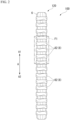
FIG. 1 is a diagram showing the overall configuration of an endoscope system including a stent device according to a first embodiment of the present invention. -
FIG. 2 is a diagram showing the overall configuration of the same stent device. -
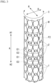
FIG. 3 is a diagram showing the overall configuration of a stent of the same stent device. -
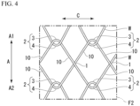
FIG. 4 is a development view of the same stent in an F2 region shown inFIG. 3 . -
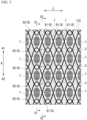
FIG. 5 is a diagram showing the same stent device in an F1 region shown inFIG. 2 . -
FIG. 6 is a cross-sectional view along line S1-S1 shown inFIG. 5 . -
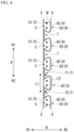
FIG. 7 is a cross-sectional view along line S2-S2 shown inFIG. 5 . -
FIG. 8 is a partially transparent view of the same stent device curved to one side. -
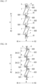
FIG. 9 is a cross-sectional view along line S3-S3 shown inFIG. 8 . -
FIG. 10 is a partially transparent view of the same stent device curved to the other side. -
FIG. 11 is a cross-sectional view along line S4-S4 shown inFIG. 10 . -
FIG. 12 is a diagram showing a modification example of an expanded accommodation portion of the same stent device. -
FIG. 13 is a cross-sectional view of a stent device according to a second embodiment of the present invention. -
FIG. 14 is a cross-sectional view of the same stent device. -
FIG. 15 is a cross-sectional view of the same stent device. -
FIG. 16 is a cross-sectional view of a stent device according to a third embodiment of the present invention. -
FIG. 17 is a cross-sectional view of the same stent device. -
FIG. 18 is a cross-sectional view of the same stent device. -
FIG. 19 is a cross-sectional view of a modification example of the same stent device. -
FIG. 20 is a cross-sectional view of the same modification example of the same stent device. -
FIG. 21 is a cross-sectional view of another modification example of the same stent device. -
FIG. 22 is a cross-sectional view of the same modification example of the same stent device. -
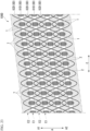
FIG. 23 is a development view of a stent device according to a fourth embodiment of the present invention. -
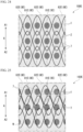
FIG. 24 is a developed view of a portion of a stent device according to a fifth embodiment of the present invention. -
FIG. 25 is a diagram showing a portion of the same stent device twisted. -
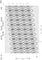
FIG. 26 is a development view of a modification example of the same stent device. - An
endoscope system 300 equipped with astent device 100 according to a first embodiment of the present invention will be described with reference toFIGS. 1 to 11 .FIG. 1 is a diagram showing the overall configuration of theendoscope system 300. - The
endoscope system 300 includes anendoscope 200 and astent delivery system 150 inserted into a channel of theendoscope 200. - The
endoscope 200 is a known side-viewing flexible endoscope and includes along insertion section 210 and anoperation section 220 provided at the proximal end portion of theinsertion section 210. Theendoscope 200 may be a direct viewing flexible endoscope. - The
insertion section 210 includes a distal endrigid portion 211 provided at the distal end portion thereof, acurving portion 212 which is provided on the proximal end side of the distal endrigid portion 211 and which can be curved, and aflexible tube portion 213 provided on the proximal end side of the curvingportion 212. A light guide 215 and an imaging unit 216 having a CCD are provided on a side surface of the distal endrigid portion 211 and exposed to the outside. - A
treatment instrument channel 230 through which a treatment instrument for an endoscope such as thestent delivery system 150 is inserted is formed in theinsertion section 210. Adistal end portion 230a of thetreatment instrument channel 230 opens on the side surface of the distal endrigid portion 211. A proximal end portion of thetreatment instrument channel 230 extends to theoperation section 220. - The distal end
rigid portion 211 of thetreatment instrument channel 230 is provided with a risingbase 214. A proximal end portion of the risingbase 214 is rotatably supported by the distal endrigid portion 211. Arising base operation wire (not shown) fixed to a distal end portion of the risingbase 214 extends to the proximal end side through theinsertion section 210. - The curving
portion 212 is configured to be able to be freely curved in an up-down direction and a left-right direction. A distal end of the operation wire is fixed to the distal end side of the curvingportion 212. The operation wire extends through theinsertion section 210 to theoperation section 220. - The proximal end side of the
operation section 220 is provided with aknob 223 for operating the operation wire and aswitch 224 for operating the imaging unit 216 and the like. A user can curve the curvingportion 212 in a desired direction by operating theknob 223. - A
forceps port 222 that communicates with thetreatment instrument channel 230 is provided on the distal end side of theoperation section 220. The user can insert a treatment instrument for an endoscope such as thestent delivery system 150 through theforceps port 222. Aforceps plug 225 is attached to theforceps port 222 in order to prevent leakage of a bodily fluid. - The
stent delivery system 150 is formed to be elongated as a whole and includes astent device 100, anouter tube member 160, aninner tube member 170, and anoperation part 140. - The
outer tube member 160 is formed of a resin or the like, has a cylindrical shape, and has flexibility. Theouter tube member 160 can be inserted into thetreatment instrument channel 230 of theendoscope 200. - The
inner tube member 170 has an outer diameter smaller than the inner diameter of theouter tube member 160 and can pass through the internal space (the lumen) of theouter tube member 160. Theinner tube member 170 is formed of a resin or the like and has flexibility. Atip 180 having an outer diameter larger than the outer diameter of theouter tube member 160 is provided at the distal end of theinner tube member 170. - The
stent device 100 is accommodated in the distal end portion of thestent delivery system 150, as shown inFIG. 1 . Thestent device 100 is accommodated in a gap between theinner tube member 170 and theouter tube member 160 in a state in which theinner tube member 170 is passed therethrough and the diameter thereof is reduced. - The
operation part 140 is connected to the proximal end sides of theouter tube member 160 and theinner tube member 170, and is configured to be able to move theouter tube member 160 relative to theinner tube member 170 in a longitudinal direction. By operating the operation part, the operator moves theouter tube member 160 relative to theinner tube member 170 to expose the accommodatedstent device 100, and as a result, thestent device 100 can be placed. Furthermore, when the stent has been exposed, the operator can re-accommodate thestent device 100 in the gap between theinner tube member 170 and theouter tube member 160 by operating theouter tube member 160 to move relative to theinner tube member 170 in an opposite direction. -
FIG. 2 is a diagram showing the overall configuration of thestent device 100. - The
stent device 100 is placed in a body lumen of a digestive system, such as a bile duct, esophagus, duodenum, small intestine, or large intestine, and is used primarily to expand and maintain the lumen. Thestent device 100 includes astent 110 and acover 120. Thestent device 100 is a covered stent in which thestent 110 formed by weaving a wire is covered with acover 120. - In the following description, one side in a longitudinal axis direction (an axial direction) A of the
stent device 100 will be referred to as a "first direction A1," and the other side in the longitudinal axis direction A of thestent device 100 will be referred to as a "second direction A2." -
FIG. 3 is a diagram showing the overall configuration of thestent 110. - The
stent 110 is formed by weaving a wire and has a cylindrical shape. -
FIG. 4 is a development view of thestent 110 in an F2 region shown inFIG. 3 . - The
stent 110 is formed into a circular tube shape with a mesh on the circumferential surface by a wire W extending obliquely in a circumferential direction C while repeating bending. Thestent 110 has a plurality of straightline intersection portions 1 and a plurality ofengagement portions 2. - The straight
line intersection portion 1 is formed bystraight line portions 10 of the wires W intersecting with each other in a straight line. Thestraight line portion 10 is a portion of the wire W having a substantially straight line shape, and also includes a gently curved portion. - The engagement portion (an intertwining portion) 2 is formed by a mountain-shaped
bent portion 3 and a valley-shapedbent portion 4 intersecting with each other. The mountain-shaped bent portion (a mountain) 3 is a convex portion that is convex toward a side in the first direction A1, in which the wire W extending obliquely in the circumferential direction C is bent back in the longitudinal axis direction A. The valley-shaped bent portion (a valley) 4 is a convex portion that is convex toward a side in the second direction A2 (a concave portion that is concave toward a side in the first direction A1), in which the wire W extending obliquely in the circumferential direction is bent back in the longitudinal axis direction A. At theengagement portion 2, the mountain-shapedbent portion 3 and the valley-shapedbent portion 4 intersect with each other in a hook shape, and thus the mountain-shapedbent portion 3 and the valley-shapedbent portion 4 are connected to each other such that they can be moved relative to each other, although they cannot be separated from each other. - In the present embodiment, the
engagement portions 2 adjacent to each other in the circumferential direction C are disposed at substantially the same position in the longitudinal axis direction A. Furthermore, theengagement portions 2 adjacent to each other in the longitudinal axis direction A are disposed at substantially the same position in the circumferential direction C. - As shown in
FIG. 3 , the plurality of straightline intersection portions 1 are disposed parallel to the circumferential direction C. Further, the plurality of straightline intersection portions 1 are disposed parallel to the circumferential direction C. A first region E1 in which the plurality of straightline intersection portions 1 are disposed and a second region E2 in which the plurality ofengagement portions 2 are disposed are alternately disposed in the longitudinal axis direction A. -
FIG. 5 is a diagram showing thestent device 100 in an F1 region shown inFIG. 2 .FIG. 6 is a cross-sectional view along line S1-S1 shown inFIG. 5 .FIG. 7 is a cross-sectional view along line S2-S2 shown inFIG. 5 . Thecover 120 covers theentire stent 110. Thecover 120 is made of a flexible material such as polytetrafluoroethylene (PTFE) or polyurethane nonwoven fabric, and can prevent infiltration of cells and blood. - As shown in
FIGS. 6 and7 , thecover 120 is formed by overlapping aninside cover 5 disposed on an inside R1 of thestent 110 in a radial direction R and anoutside cover 6 disposed on the outside R2 of thestent 110 in the radial direction R each other. Theinside cover 5 and theoutside cover 6 may be formed integrally or may be formed separately. Specifically, thecover 120 includes afixation portion 7 at which theinside cover 5 and theoutside cover 6 are fixed to each other, and anaccommodation portion 8 in which the wire W is accommodated. - As shown in
FIG. 5 , the fixation portion (a fixation region) 7 is a region sandwiched between theengagement portions 2 adj acent to each other in the longitudinal axis direction A, and is formed into a roughly diamond-shaped region surrounded by the mountain-shapedbent portion 3 and the valley-shapedbent portion 4. As shown inFIG. 6 , thefixation portion 7 is a region in which theinside cover 5 and theoutside cover 6 are fixed to each other by bonding, pressure bonding, or the like. Since theinside cover 5 and theoutside cover 6 are fixed to each other, the wire W cannot pass through thefixation portion 7. - The accommodation portion (a non-fixation region) 8 is a region formed by the
inside cover 5 and theoutside cover 6 that are not fixed to each other. Theaccommodation portion 8 accommodates the wire W in an internal region sandwiched between theinside cover 5 and theoutside cover 6. As shown inFIGS. 6 and7 , theaccommodation portion 8 has anormal accommodation portion 81 and an expandedaccommodation portion 82 that is wider than thenormal accommodation portion 81 in the radial direction R. - As shown in
FIGS. 5 and7 , thenormal accommodation portion 81 is formed by theinside cover 5 extending in the longitudinal axis direction A and theoutside cover 6 extending in the longitudinal axis direction A. Thenormal accommodation portion 81 is formed in the first region E1 in which the plurality of straightline intersection portions 1 are disposed in the circumferential direction C. Thenormal accommodation portion 81 accommodates the straightline intersection portion 1 and the wire W near the straightline intersection portion 1 in an internal region sandwiched between theinside cover 5 and theoutside cover 6. - As shown in
FIGS. 5 and6 , the expandedaccommodation portion 82 is formed by anon-expanded portion 51 that is a portion of theinside cover 5 extending in the longitudinal axis direction A and an externally expandedportion 62 formed by a portion of theoutside cover 6 bulging to the outside R2. The expandedaccommodation portion 82 is formed in the second region E2 in which the plurality ofengagement portions 2 are disposed in the circumferential direction C. The expandedaccommodation portion 82 accommodates the plurality ofengagement portions 2 disposed in the circumferential direction C in an internal region sandwiched between theinside cover 5 and theoutside cover 6. The expandedaccommodation portion 82 may be formed separately for eachengagement portion 2. - In the cross section along line S1-S1 shown in
FIG. 6 , thefixation portions 7 and the expandedaccommodation portions 82 are alternately disposed one by one. Further, in the cross section along the line S1-S1 shown inFIG. 6 , thenon-expanded portion 51 of theinside cover 5 closes an opening of the externally expandedportion 62 of theoutside cover 6. - As shown in
FIG. 6 , at least a portion of the externally expandedportion 62 is displaceable to a position at which the at least a portion of the externally expandedportion 62 overlaps thefixation portion 7 when viewed in the radial direction R. In addition, the externally expandedportion 62 of theoutside cover 6 may have elasticity, and may be deformed to be displaceable to a position at which the externally expandedportion 62 overlaps thefixation portion 7 when viewed in the radial direction R. - As shown in
FIG. 6 , thefixation portions 7 disposed on both sides of the expandedaccommodation portion 82 in the longitudinal axis direction A are defined as afirst fixation portion 71 and asecond fixation portion 72. A path length L2 of theoutside cover 6 from thefirst fixation portion 71 to thesecond fixation portion 72 is longer than a path length L1 of theinside cover 5 from thefirst fixation portion 71 to thesecond fixation portion 72. - A surface area of the externally expanded
portion 62 of theoutside cover 6 forming the expandedaccommodation portion 82 is larger than a surface area of thenon-expanded portion 51 of theinside cover 5 forming the expandedaccommodation portion 82. - In the cross section along line S2-S2 shown in
FIG. 7 , thenormal accommodation portion 81 and the expandedaccommodation portions 82 are alternately disposed one by one. In the cross section along line S2-S2 shown inFIG. 7 , the internal region of the expandedaccommodation portion 82 is connected to the internal region of thenormal accommodation portion 81. - Next, the curving operation of the
stent device 100 will be explained. In the following description, theengagement portion 2 disposed on the inside in a curving direction will be referred to as an "insideengagement portion 2A." Moreover, theengagement portion 2 disposed on the outside in the curving direction will be referred to as an "outside engagement portion 2B." -
FIG. 8 is a partially transparent view of thestent device 100 curved to one side.FIG. 9 is a cross-sectional view along line S3-S3 shown inFIG. 8 . The mountain-shapedbent portion 3 of theinside engagement portion 2A accommodated in the expandedaccommodation portion 82 is movable in the first direction A1 to a position at which the mountain-shapedbent portion 3 overlaps thefixation portion 7 when viewed in the radial direction R. The valley-shapedbent portion 4 of theinside engagement portion 2A accommodated in the expandedaccommodation portion 82 is movable in the second direction A2 to a position at which the mountain-shapedbent portion 4 overlaps thefixation portion 7 when viewed in the radial direction R. For this reason, in the curving operation of thestent device 100, the operation of the mountain-shapedbent portion 3 and the valley-shapedbent portion 4 of theinside engagement portion 2A away from each other is not impeded by thefixation portion 7. -
FIG. 10 is a partially transparent view of thestent device 100 curved to the other side.FIG. 11 is a cross-sectional view along line S4-S4 shown inFIG. 10 . The mountain-shapedbent portion 3 of theoutside engagement portion 2B accommodated in the expandedaccommodation portion 82 is movable in the second direction A2 until the mountain-shapedbent portion 3 comes into contact with the valley-shapedbent portion 4. The valley-shapedbent portion 4 of theoutside engagement portion 2B accommodated in the expandedaccommodation portion 82 is movable in the first direction A1 until the valley-shapedbent portion 4 comes into contact with the mountain-shapedbent portion 3. For this reason, in the curving operation of thestent device 100, the motion of the mountain-shapedbent portion 3 and the valley-shapedbent portion 4 of theoutside engagement portion 2B toward each other is not impeded by thefixation portion 7. - A stent placement method using the
endoscope system 300 including thestent delivery system 150 will be described using a technique for placing thestent device 100 in a bile duct as an example. - The operator inserts the
insertion section 210 of theendoscope 200 into the patient's body cavity through a natural opening such as the mouth. At that time, the operator operates theknob 223 and the like to curve the curvingportion 212 as necessary. - The operator passes a guide wire through the
treatment instrument channel 230 of theendoscope 200 and inserts the guide wire into the bile duct while observing with theendoscope 200. Next, the operator operates the guide wire under X-ray fluoroscopy to break through the narrow portion in the bile duct, and moves the distal end portion of the guide wire to the liver side from the narrow portion (a target position). - The operator inserts the proximal end portion of the guide wire protruding from the forceps plug 225 of the
endoscope 200 into a through hole of thetip 180 of thestent delivery system 150. - The operator advances the
stent delivery system 150 along the guide wire by pushing thestent delivery system 150 while holding the guidewire. The distal end portion of thestent delivery system 150 protrudes from the distal end portion of thetreatment instrument channel 230 of theendoscope 200. When the distal end portion of thestent delivery system 150 breaks through the narrow portion (the target position), the operator advances and retracts thestent delivery system 150 to determine the placement position of thestent device 100. The operator may insert thestent delivery system 150 into thetreatment instrument channel 230 without using the guide wire. - After the target position of the
stent device 100 is determined, the operator retracts theouter tube member 160 with respect to theinner tube member 170. As a result, as shown inFIG. 1 , thestent device 100 is gradually exposed and expanded from the distal end side. - When
stent device 100 is fully exposed, thestent device 100 is expanded in its entirety such that the inner diameter of thestent device 100 is greater than the outer diameter ofinner tube member 170. Accordingly, the engagement between thestent device 100 and theinner tube member 170 is released. - After the engagement between the
stent device 100 and theinner tube member 170 is released, when the operator retracts theinner tube member 170, thestent device 100 remains in the placement position and theinner tube member 170 is removed from thestent device 100. - When the operator pulls out the
stent delivery system 150 except for thestent device 100 from the body, the procedure for placing thestent device 100 is completed. - According to the
stent device 100 according to the present embodiment, even if thestent 110 is covered with thecover 120, thestent device 100 is easily curved. The curving operation is not impeded by thefixation portion 7 whether theengagement portion 2 is disposed on the inside or on the outside in the curving direction. - In the above, the first embodiment of the present invention has been described in detail with reference to the drawings, but the specific configuration is not limited to the embodiment, and a design change and the like within a range not departing from the gist of the present invention are also included. In addition, the constituent elements shown in the above-described embodiment and a modification example shown below can be appropriately combined and configured.
- In the present embodiment, the expanded
accommodation portion 82 is formed by thenon-expanded portion 51 of theinside cover 5 and the externally expandedportion 62 of theoutside cover 6. However, the aspect of the expandedaccommodation portion 82 is not limited to this.FIG. 12 is a diagram showing an expanded accommodation portion 82Athat is a modification example of the expandedaccommodation portion 82. The expandedaccommodation portion 82A is formed by an internally expandedportion 52 formed by a portion of theinside cover 5 bulging to the inside R1 and anon-expanded portion 61 that is a portion of theoutside cover 6 extending in the longitudinal axis direction A. - A second embodiment of the present invention will be described with reference to
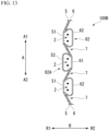
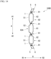
FIGS. 13 to 15 . In the following description, the same constituent elements as those already described are designated by the same reference signs, and duplicate description will be omitted. Astent device 100B according to the second embodiment is accommodated in astent delivery system 150 similarly to thestent device 100 according to the first embodiment. Thestent device 100B includes astent 110 and a cover 120B. -
FIG. 13 is a cross-sectional view of thestent device 100B including afixation portion 7 and expandedaccommodation portions FIG. 14 is a cross-sectional view of thestent device 100B including anormal accommodation portion 81 and the expandedaccommodation portions FIG. 15 is a cross-sectional view of thestent device 100B including aninside engagement portion 2A. - As shown in
FIGS. 13 and14 , in the cover 120B, the expandedaccommodation portions 82 and the expandedaccommodation portions 82A are alternately arranged one by one in the longitudinal axis direction A. The cover 120B is difficult to be bulked up in the radial direction R than thecover 120 of the first embodiment. For this reason, the operator easily releases thestent device 100B from thestent delivery system 150. Further, the operator easily recaptures thestent device 100B in thestent delivery system 150. - As shown in
FIG. 15 , a mountain-shapedbent portion 3 of theinside engagement portion 2A accommodated in the expandedaccommodation portion 82 is movable in the first direction A1 to a position at which the mountain-shapedbent portion 3 overlaps thefixation portion 7 when viewed in the radial direction R. A valley-shapedbent portion 4 of theinside engagement portion 2A accommodated in the expandedaccommodation portion 82 is movable in the second direction A2 to a position at which the mountain-shapedbent portion 4 overlaps thefixation portion 7 when viewed in the radial direction R. For this reason, in the curving operation of thestent device 100B, the operation of the mountain-shapedbent portion 3 and the valley-shapedbent portion 4 of theinside engagement portion 2A away from each other is not impeded by thefixation portion 7. - According to the
stent device 100B according to the present embodiment, even if thestent 110 is covered with the cover 120B, thestent device 100B is easily curved. The curving operation is not impeded by thefixation portion 7 whether theengagement portion 2 is disposed on the inside or on the outside in the curving direction. - In the above, the second embodiment of the present invention has been described in detail with reference to the drawings, but the specific configuration is not limited to the embodiment, and a design change and the like within a range not departing from the gist of the present invention are also included. In addition, the constituent elements shown in the above-described embodiment and a modification example can be appropriately combined and configured.
- In the embodiment described above, the expanded
accommodation portions 82 and the expandedaccommodation portions 82A are alternately arranged one by one in the longitudinal axis direction A. However, the arrangement aspect of the expandedaccommodation portion 82 and the expandedaccommodation portion 82A is not limited to this. For example, the expandedaccommodation portions 82 and the expandedaccommodation portions 82A may be arranged such that two consecutive expandedaccommodation portions 82 and one expandedaccommodation portion 82A are alternately arranged. - A third embodiment of the present invention will be described with reference to
FIGS. 16 to 18 . In the following description, the same constituent elements as those already described are designated by the same reference signs, and duplicate description will be omitted. A stent device 100C according to the third embodiment is accommodated in astent delivery system 150 similarly to thestent device 100 according to the first embodiment. The stent device 100C includes astent 110 and a cover 120C. -
FIG. 16 is a cross-sectional view of the stent device 100C including afixation portion 7 and an expandedaccommodation portion 82C.FIG. 17 is a cross-sectional view of the stent device 100C including anormal accommodation portion 81 and the expandedaccommodation portion 82C.FIG. 18 is a cross-sectional view of the stent device 100C including aninside engagement portion 2A. - As shown in
FIGS. 16 and17 , the cover 120C has the expandedaccommodation portion 82C instead of the expandedaccommodation portion 82 of the first embodiment. The expandedaccommodation portion 82C is formed by an internally expandedportion 52C formed by a portion of theinside cover 5 bulging to the inside R1 and an externally expandedportion 62C formed by a portion of theoutside cover 6 bulging to the outside R2. The expandedaccommodation portion 82C accommodates theengagement portion 2 in an internal region sandwiched between theinside cover 5 and theoutside cover 6. - The cover 120C is difficult to be bulked up in the radial direction R than the
cover 120 of the first embodiment. For this reason, the operator easily releases the stent device 100C from thestent delivery system 150. Further, the operator easily recaptures the stent device 100C in thestent delivery system 150. - As shown in
FIG. 18 , a mountain-shapedbent portion 3 of theinside engagement portion 2A accommodated in the expandedaccommodation portion 82C is movable in the first direction A1 to a position at which the mountain-shapedbent portion 3 overlaps thefixation portion 7 when viewed in the radial direction R. A valley-shapedbent portion 4 of theinside engagement portion 2A accommodated in the expandedaccommodation portion 82C is movable in the second direction A2 to a position at which the mountain-shapedbent portion 4 overlaps thefixation portion 7 when viewed in the radial direction R. For this reason, in the curving operation of the stent device 100C, the operation of the mountain-shapedbent portion 3 and the valley-shapedbent portion 4 of theinside engagement portion 2A away from each other is not impeded by thefixation portion 7. - According to the stent device 100C according to the present embodiment, even if the
stent 110 is covered with the cover 120C, the stent device 100C is easily curved. The curving operation is not impeded by thefixation portion 7 whether theengagement portion 2 is disposed on the inside or on the outside in the curving direction. - In the above, the third embodiment of the present invention has been described in detail with reference to the drawings, but the specific configuration is not limited to the embodiment, and a design change and the like within a range not departing from the gist of the present invention are also included. In addition, the constituent elements shown in the above-described embodiment and a modification example can be appropriately combined and configured.
-
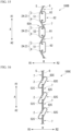
FIGS. 19 and 20 are cross-sectional views of an expanded accommodation portion 82C1 that is a modification example of the expandedaccommodation portion 82C. The expanded accommodation portion 82C1 is formed by the internally expandedportion 52C and the externally expandedportion 62C similarly to the expandedaccommodation portion 82C. In the expanded accommodation portion 82C1, the externally expandedportion 62C is attached to thefixation portion 7 by abonding portion 9 while extending in the first direction A1. Further, the internally expandedportion 52C is attached to thefixation portion 7 by thebonding portion 9 while extending in the second direction A2. The expanded accommodation portion 82C1 is difficult to be bulked up in the radial direction R, and does not impede the operation of theengagement portion 2. -
FIGS. 21 and 22 are cross-sectional views of an expanded accommodation portion 82C2 that is a modification example of the expandedaccommodation portion 82C. The expanded accommodation portion 82C2 is formed by the internally expandedportion 52C and the externally expandedportion 62C similarly to the expandedaccommodation portion 82C. In the expanded accommodation portion 82C2, adistal end portion 62t of the externally expandedportion 62C is fixed to the mountain-shapedbent portion 3. Further, in the expanded accommodation portion 82C2, adistal end portion 52t of the internally expandedportion 52C is fixed to the valley-shapedbent portion 4. As shown inFIG. 22 , the expanded accommodation portion 82C1 is difficult to be bulked up in the radial direction R. - A fourth embodiment of the present invention will be described with reference to
FIG. 23 . In the following description, the same constituent elements as those already described are designated by the same reference signs, and duplicate description will be omitted. Astent device 100D according to the fourth embodiment is accommodated in astent delivery system 150 similarly to thestent device 100 according to the first embodiment. Thestent device 100D includes astent 110D and a cover 120D. -
FIG. 23 is a development view of thestent device 100D developed in the circumferential direction C. - The
stent 110D differs from thestent 110 of the first embodiment only in the arrangement of a plurality of straightline intersection portions 1 and a plurality ofengagement portions 2. In thestent 110D, a first region E1 in which the plurality of straightline intersection portions 1 are disposed and a second region E2 in which the plurality ofengagement portions 2 are disposed are alternately disposed in the longitudinal axis direction A. The first region E1 is disposed spirally in the longitudinal axis direction A. Further, the second region E2 is disposed spirally in the longitudinal axis direction A. - The cover 120D includes a
fixation portion 7 at which aninside cover 5 and anoutside cover 6 are fixed to each other, and anaccommodation portion 8D in which the wire W is accommodated. - The accommodation portion (a non-fixation region) 8D is a region formed by the
inside cover 5 and theoutside cover 6 that are not fixed to each other similarly to theaccommodation portion 8. Theaccommodation portion 8D has anormal accommodation portion 81D and an expandedaccommodation portion 82D that is wider than thenormal accommodation portion 81D in the radial direction R. - The
normal accommodation portion 81D is formed in the first region E1 in which the plurality of straightline intersection portions 1 are disposed spirally in the longitudinal axis direction A. The expandedaccommodation portion 82D is formed in the second region E2 in which the plurality ofengagement portions 2 are disposed spirally in the longitudinal axis direction A. - According to the
stent device 100D according to the present embodiment, even if thestent 110D is covered with the cover 120D, thestent device 100D is easily curved. The curving operation is not impeded by thefixation portion 7 whether theengagement portion 2 is disposed on the inside or on the outside in the curving direction. - In the above, the fourth embodiment of the present invention has been described in detail with reference to the drawings, but the specific configuration is not limited to the embodiment, and a design change and the like within a range not departing from the gist of the present invention are also included. In addition, the constituent elements shown in the above-described embodiment and a modification example can be appropriately combined and configured.
- A method of weaving the stent is not limited to that of the
stent 110 of the first embodiment or that of thestent 110D of the fourth embodiment. Other methods of weaving the stent may be used. - A fifth embodiment of the present invention will be described with reference to
FIGS. 24 and 25 . In the following description, the same constituent elements as those already described are designated by the same reference signs, and duplicate description will be omitted. Astent device 100E according to the fifth embodiment is accommodated in astent delivery system 150 similarly to thestent device 100 according to the first embodiment. Thestent device 100E includes astent 110 and a cover 120E. -
FIG. 24 is a diagram showing a portion of thestent device 100E. - The cover 120E is formed by overlapping an
inside cover 5 disposed on an inside R1 of thestent 110 in a radial direction R and anoutside cover 6 disposed on the outside R2 of thestent 110 in the radial direction R each other similarly to thecover 120 of the first embodiment. Specifically, the cover 120E includes afixation portion 7 at which theinside cover 5 and theoutside cover 6 are fixed to each other, and anaccommodation portion 8E in which the wire W is accommodated. - The accommodation portion (a non-fixation region) 8E is a region formed by the
inside cover 5 and theoutside cover 6 that are not fixed to each other similarly to theaccommodation portion 8. Theaccommodation portion 8E has anormal accommodation portion 81E and an expandedaccommodation portion 82E that is wider than thenormal accommodation portion 81E in the radial direction R. - The
normal accommodation portion 81E is formed in a third region E3 in which the plurality ofengagement portions 2 are arranged in the longitudinal axis direction A. The expandedaccommodation portion 82E is formed in a fourth region E4 in which the plurality of straightline intersection portions 1 are arranged in the longitudinal axis direction A. The expandedaccommodation portion 82E accommodates the plurality of straightline intersection portions 1 disposed in the longitudinal axis direction A and the wires W near the straightline intersection portions 1 in an internal region sandwiched between theinside cover 5 and theoutside cover 6. -
FIG. 25 is a diagram showing a portion of thestent device 100E twisted. - Even in a case where the
stent device 100E is twisted, as shown inFIG. 25 , the straightline intersection portion 1 and the wire W near the straightline intersection portion 1 are movable to a position at which they overlap thefixation portion 7 when viewed in the radial direction R. - According to the
stent device 100E according to the present embodiment, even if thestent 110 is covered with the cover 120D, thestent device 100E is easily curved. - In the above, the fifth embodiment of the present invention has been described in detail with reference to the drawings, but the specific configuration is not limited to the embodiment, and a design change and the like within a range not departing from the gist of the present invention are also included. In addition, the constituent elements shown in the above-described embodiment and a modification example can be appropriately combined and configured.
-
FIG. 26 is a development view of a stent device 100E1 that is a modification example of thestent device 100E. The stent device 100E1 includes astent 110D and a cover 120E. The expandedaccommodation portion 82E is formed as a continuous region in the longitudinal axis direction A. For this reason, even in a case where the straightline intersection portion 1 and theengagement portion 2 are disposed in a spiral in the longitudinal axis direction A as in thestent 110D, the manufacturing cost of the expandedaccommodation portion 82E is low. - The present invention can be applied to a stent covered with a cover.
-
- 300 Endoscope system
- 200 Endoscope
- 150 Stent delivery system
- 140 Operation part
- 160 Outer tube member
- 170 Inner tube member
- 180 Tip
- 100, 100B, 100C, 100D, 100E Stent device
- 110, 110D Stent
- 120, 120B, 120C, 120D, 120E Cover
- 1 Straight line intersection portion
- 10 Straight line portion
- 2 Engagement portion (intertwining portion)
- 3 Mountain-shaped bent portion (mountain)
- 4 Valley-shaped bent portion (valley)
- 5 Inside cover
- 6 Outside cover
- 7 Fixation portion
- 8 Accommodation portion
- 81 Normal accommodation portion
- 82 Expanded accommodation portion
Claims (14)
- A stent device comprising:a stent formed in a cylindrical shape by weaving a wire; anda cover formed by overlapping an inside cover disposed on an inside of the stent and an outside cover disposed on an outside of the stent,wherein the cover hasa fixation portion at which the inside cover and the outside cover are fixed to each other, andan accommodation portion which is formed by the inside cover and the outside cover and accommodates the wire, andwherein the accommodation portion has a normal accommodation portion and an expanded accommodation portion that is wider than the normal accommodation portion in a radial direction.
- The stent device according to claim 1, wherein the expanded accommodation portion is displaceable to a position at which at least a portion thereof overlaps the fixation portion when viewed in the radial direction.
- The stent device according to claim 1,wherein the outside cover has an externally expanded portion formed by a portion of the outside cover bulging to the outside, andwherein the expanded accommodation portion is formed by the externally expanded portion of the outside cover and a portion of the inside cover extending in an axial direction.
- The stent device according to claim 3, wherein at least a portion of the externally expanded portion is displaceable to a position at which the at least a portion of the externally expanded portion overlaps the fixation portion when viewed in the radial direction.
- The stent device according to claim 3,wherein the expanded accommodation portion is disposed between a first fixation portion and a second fixation portion, each of which is the fixation portion, andwherein a path length of the outside cover from the first fixation portion to the second fixation portion is longer than a path length of the inside cover from the first fixation portion to the second fixation portion.
- The stent device according to claim 3, wherein a surface area of the externally expanded portion of the outside cover forming the expanded accommodation portion is larger than a surface area of the portion of the inside cover forming the expanded accommodation portion.
- The stent device according to claim 1,wherein the outside cover has an externally expanded portion formed by a portion of the outside cover bulging to the outside,wherein the inside cover has an internally expanded portion formed by a portion of the inside cover bulging to the inside, andwherein the expanded accommodation portion is formed by the externally expanded portion of the outside cover and the internally expanded portion of the inside cover.
- The stent device according to any one of claims 1 to 7,wherein the stent has an engagement portion at which a mountain-shaped bent portion that is bent toward a side in a first direction, which is one side in an axial direction, and becomes convex, and a valley-shaped bent portion that is bent toward a side in a second direction, which is the other side in the axial direction, and becomes convex intersect with each other, andwherein the expanded accommodation portion accommodates the engagement portion.
- The stent device according to claim 8, wherein the fixation portion and the expanded accommodation portion are arranged in the axial direction.
- The stent device according to claim 9, wherein the mountain-shaped bent portion accommodated in the expanded accommodation portion is movable in the first direction to a position at which the mountain-shaped bent portion overlaps the fixation portion when viewed in the radial direction.
- The stent device according to claim 9, wherein the valley-shaped bent portion accommodated in the expanded accommodation portion is movable in the second direction to a position at which the mountain-shaped bent portion overlaps the fixation portion when viewed in the radial direction.
- The stent device according to any one of claims 8 to 11,wherein a plurality of the engagement portions are arranged in a circumferential direction, andwherein the expanded accommodation portion is formed in a region continuous in the circumferential direction and accommodates the plurality of engagement portions.
- The stent device according to claim 8,wherein the stent has a straight line intersection portion at which straight line portions intersect with each other, andwherein the normal accommodation portion accommodates the straight line intersection portion.
- A stent delivery system comprising:an operation part;an outer tube member configured to extend to a distal side from the operation part;an inner tube member configured to extend to a distal side from the operation part and located on an inside of the outer tube member; andthe stent device according to any one of claims 1 to 13 which is accommodated between the outer tube member and the inner tube member,wherein the operation part is configured to place the stent device by moving the outer tube member or the inner tube member in a longitudinal direction.
Applications Claiming Priority (1)
| Application Number | Priority Date | Filing Date | Title |
|---|---|---|---|
| PCT/JP2021/032146 WO2023032084A1 (en) | 2021-09-01 | 2021-09-01 | Stent device and stent delivery system |
Publications (2)
| Publication Number | Publication Date |
|---|---|
| EP4397284A1 true EP4397284A1 (en) | 2024-07-10 |
| EP4397284A4 EP4397284A4 (en) | 2025-07-02 |
Family
ID=85410928
Family Applications (1)
| Application Number | Title | Priority Date | Filing Date |
|---|---|---|---|
| EP21955974.7A Pending EP4397284A4 (en) | 2021-09-01 | 2021-09-01 | STENT DEVICE AND STENT DELIVERY SYSTEM |
Country Status (6)
| Country | Link |
|---|---|
| US (1) | US20240189125A1 (en) |
| EP (1) | EP4397284A4 (en) |
| JP (1) | JP7587049B2 (en) |
| KR (1) | KR20240033283A (en) |
| CN (1) | CN117897121A (en) |
| WO (1) | WO2023032084A1 (en) |
Families Citing this family (1)
| Publication number | Priority date | Publication date | Assignee | Title |
|---|---|---|---|---|
| CN120857917A (en) * | 2023-04-05 | 2025-10-28 | 奥林巴斯株式会社 | Bracket device |
Family Cites Families (7)
| Publication number | Priority date | Publication date | Assignee | Title |
|---|---|---|---|---|
| GB2346559A (en) | 1998-12-23 | 2000-08-16 | Stephen George Edward Barker | Endoluminal stent |
| US20050060020A1 (en) | 2003-09-17 | 2005-03-17 | Scimed Life Systems, Inc. | Covered stent with biologically active material |
| GB2449784B8 (en) * | 2004-02-09 | 2009-04-29 | Cook Biotech Inc | Stent graft devices having collagen coating. |
| US8034096B2 (en) * | 2004-03-31 | 2011-10-11 | Cook Medical Technologies Llc | Stent-graft with graft to graft attachment |
| JP5813230B2 (en) * | 2012-07-13 | 2015-11-17 | 株式会社パイオラックスメディカルデバイス | Stent |
| KR101557010B1 (en) * | 2014-07-11 | 2015-10-02 | 주식회사 비씨엠 | A Covered Stents and the making Methods for a Covered Stent |
| WO2021166156A1 (en) | 2020-02-20 | 2021-08-26 | オリンパス株式会社 | Stent delivery system, endoscope system, and stenting method |
-
2021
- 2021-09-01 KR KR1020247006275A patent/KR20240033283A/en not_active Withdrawn
- 2021-09-01 JP JP2023544877A patent/JP7587049B2/en active Active
- 2021-09-01 EP EP21955974.7A patent/EP4397284A4/en active Pending
- 2021-09-01 WO PCT/JP2021/032146 patent/WO2023032084A1/en not_active Ceased
- 2021-09-01 CN CN202180101942.7A patent/CN117897121A/en active Pending
-
2024
- 2024-02-26 US US18/587,198 patent/US20240189125A1/en active Pending
Also Published As
| Publication number | Publication date |
|---|---|
| KR20240033283A (en) | 2024-03-12 |
| CN117897121A (en) | 2024-04-16 |
| JP7587049B2 (en) | 2024-11-19 |
| WO2023032084A1 (en) | 2023-03-09 |
| EP4397284A4 (en) | 2025-07-02 |
| US20240189125A1 (en) | 2024-06-13 |
| JPWO2023032084A1 (en) | 2023-03-09 |
Similar Documents
| Publication | Publication Date | Title |
|---|---|---|
| EP2512318B1 (en) | Endoscope sheath | |
| JP5252606B2 (en) | Endoscopic treatment tool | |
| JP5064077B2 (en) | Medical snare device | |
| US20070265494A1 (en) | Flexible and retractable endoscope elevator | |
| JP2016507303A (en) | Endoscope sleeve | |
| JPWO2010082399A1 (en) | Endoscopic treatment tool | |
| JP5409363B2 (en) | Loop tip wire guide | |
| US20240189125A1 (en) | Stent device and stent delivery system | |
| KR20160138004A (en) | Stent delivery system and endoscope system | |
| US8419695B2 (en) | Apparatus and method of maintaining insufflation | |
| JP5631177B2 (en) | Endoscope tubular member | |
| US20260013979A1 (en) | Stent device | |
| EP4397283A1 (en) | Stent and stent delivery system | |
| JP4527111B2 (en) | Guide wire structure for insertion into the interior space | |
| US20240245539A1 (en) | Stent and stent delivery system | |
| CN114931692B (en) | Catheter system | |
| KR100351320B1 (en) | Catheter | |
| CN115040756A (en) | Catheter supporting device and lumen intervention system | |
| US12589015B2 (en) | Stent delivery system, endoscope system, and stent indwelling method | |
| JP2026027746A (en) | stents | |
| KR20260054409A (en) | Plastic stent | |
| JP2705701B2 (en) | Endoscope system | |
| JP2022059511A (en) | catheter | |
| JP2000102543A (en) | Tubular medical instruments | |
| CN117771518A (en) | Catheter insertion equipment, catheter devices |
Legal Events
| Date | Code | Title | Description |
|---|---|---|---|
| STAA | Information on the status of an ep patent application or granted ep patent |
Free format text: STATUS: THE INTERNATIONAL PUBLICATION HAS BEEN MADE |
|
| PUAI | Public reference made under article 153(3) epc to a published international application that has entered the european phase |
Free format text: ORIGINAL CODE: 0009012 |
|
| STAA | Information on the status of an ep patent application or granted ep patent |
Free format text: STATUS: REQUEST FOR EXAMINATION WAS MADE |
|
| 17P | Request for examination filed |
Effective date: 20240222 |
|
| AK | Designated contracting states |
Kind code of ref document: A1 Designated state(s): AL AT BE BG CH CY CZ DE DK EE ES FI FR GB GR HR HU IE IS IT LI LT LU LV MC MK MT NL NO PL PT RO RS SE SI SK SM TR |
|
| DAV | Request for validation of the european patent (deleted) | ||
| DAX | Request for extension of the european patent (deleted) | ||
| A4 | Supplementary search report drawn up and despatched |
Effective date: 20250604 |
|
| RIC1 | Information provided on ipc code assigned before grant |
Ipc: A61F 2/90 20130101AFI20250528BHEP |
|
| GRAP | Despatch of communication of intention to grant a patent |
Free format text: ORIGINAL CODE: EPIDOSNIGR1 |
|
| STAA | Information on the status of an ep patent application or granted ep patent |
Free format text: STATUS: GRANT OF PATENT IS INTENDED |
|
| INTG | Intention to grant announced |
Effective date: 20251117 |
|
| GRAJ | Information related to disapproval of communication of intention to grant by the applicant or resumption of examination proceedings by the epo deleted |
Free format text: ORIGINAL CODE: EPIDOSDIGR1 |
|
| STAA | Information on the status of an ep patent application or granted ep patent |
Free format text: STATUS: REQUEST FOR EXAMINATION WAS MADE |
|
| GRAP | Despatch of communication of intention to grant a patent |
Free format text: ORIGINAL CODE: EPIDOSNIGR1 |
|
| STAA | Information on the status of an ep patent application or granted ep patent |
Free format text: STATUS: GRANT OF PATENT IS INTENDED |
|
| INTC | Intention to grant announced (deleted) | ||
| INTG | Intention to grant announced |
Effective date: 20260213 |