EP4397271A1 - Patientenneuregistrierungssysteme - Google Patents
Patientenneuregistrierungssysteme Download PDFInfo
- Publication number
- EP4397271A1 EP4397271A1 EP24150155.0A EP24150155A EP4397271A1 EP 4397271 A1 EP4397271 A1 EP 4397271A1 EP 24150155 A EP24150155 A EP 24150155A EP 4397271 A1 EP4397271 A1 EP 4397271A1
- Authority
- EP
- European Patent Office
- Prior art keywords
- registration
- implant
- bone
- apex
- probe
- Prior art date
- Legal status (The legal status is an assumption and is not a legal conclusion. Google has not performed a legal analysis and makes no representation as to the accuracy of the status listed.)
- Granted
Links
Images


Classifications
-
- A—HUMAN NECESSITIES
- A61—MEDICAL OR VETERINARY SCIENCE; HYGIENE
- A61B—DIAGNOSIS; SURGERY; IDENTIFICATION
- A61B34/00—Computer-aided surgery; Manipulators or robots specially adapted for use in surgery
- A61B34/20—Surgical navigation systems; Devices for tracking or guiding surgical instruments, e.g. for frameless stereotaxis
-
- A—HUMAN NECESSITIES
- A61—MEDICAL OR VETERINARY SCIENCE; HYGIENE
- A61B—DIAGNOSIS; SURGERY; IDENTIFICATION
- A61B17/00—Surgical instruments, devices or methods
- A61B17/56—Surgical instruments or methods for treatment of bones or joints; Devices specially adapted therefor
- A61B17/58—Surgical instruments or methods for treatment of bones or joints; Devices specially adapted therefor for osteosynthesis, e.g. bone plates, screws or setting implements
- A61B17/68—Internal fixation devices, including fasteners and spinal fixators, even if a part thereof projects from the skin
- A61B17/80—Cortical plates, i.e. bone plates; Instruments for holding or positioning cortical plates, or for compressing bones attached to cortical plates
- A61B17/808—Instruments for holding or positioning bone plates, or for adjusting screw-to-plate locking mechanisms
-
- A—HUMAN NECESSITIES
- A61—MEDICAL OR VETERINARY SCIENCE; HYGIENE
- A61B—DIAGNOSIS; SURGERY; IDENTIFICATION
- A61B34/00—Computer-aided surgery; Manipulators or robots specially adapted for use in surgery
- A61B34/10—Computer-aided planning, simulation or modelling of surgical operations
-
- A—HUMAN NECESSITIES
- A61—MEDICAL OR VETERINARY SCIENCE; HYGIENE
- A61B—DIAGNOSIS; SURGERY; IDENTIFICATION
- A61B34/00—Computer-aided surgery; Manipulators or robots specially adapted for use in surgery
- A61B34/30—Surgical robots
-
- A—HUMAN NECESSITIES
- A61—MEDICAL OR VETERINARY SCIENCE; HYGIENE
- A61B—DIAGNOSIS; SURGERY; IDENTIFICATION
- A61B34/00—Computer-aided surgery; Manipulators or robots specially adapted for use in surgery
- A61B34/70—Manipulators specially adapted for use in surgery
- A61B34/76—Manipulators having means for providing feel, e.g. force or tactile feedback
-
- A—HUMAN NECESSITIES
- A61—MEDICAL OR VETERINARY SCIENCE; HYGIENE
- A61B—DIAGNOSIS; SURGERY; IDENTIFICATION
- A61B17/00—Surgical instruments, devices or methods
- A61B17/56—Surgical instruments or methods for treatment of bones or joints; Devices specially adapted therefor
- A61B2017/564—Methods for bone or joint treatment
-
- A—HUMAN NECESSITIES
- A61—MEDICAL OR VETERINARY SCIENCE; HYGIENE
- A61B—DIAGNOSIS; SURGERY; IDENTIFICATION
- A61B34/00—Computer-aided surgery; Manipulators or robots specially adapted for use in surgery
- A61B34/10—Computer-aided planning, simulation or modelling of surgical operations
- A61B2034/101—Computer-aided simulation of surgical operations
- A61B2034/105—Modelling of the patient, e.g. for ligaments or bones
-
- A—HUMAN NECESSITIES
- A61—MEDICAL OR VETERINARY SCIENCE; HYGIENE
- A61B—DIAGNOSIS; SURGERY; IDENTIFICATION
- A61B34/00—Computer-aided surgery; Manipulators or robots specially adapted for use in surgery
- A61B34/10—Computer-aided planning, simulation or modelling of surgical operations
- A61B2034/108—Computer aided selection or customisation of medical implants or cutting guides
-
- A—HUMAN NECESSITIES
- A61—MEDICAL OR VETERINARY SCIENCE; HYGIENE
- A61B—DIAGNOSIS; SURGERY; IDENTIFICATION
- A61B34/00—Computer-aided surgery; Manipulators or robots specially adapted for use in surgery
- A61B34/20—Surgical navigation systems; Devices for tracking or guiding surgical instruments, e.g. for frameless stereotaxis
- A61B2034/2046—Tracking techniques
- A61B2034/2051—Electromagnetic tracking systems
-
- A—HUMAN NECESSITIES
- A61—MEDICAL OR VETERINARY SCIENCE; HYGIENE
- A61B—DIAGNOSIS; SURGERY; IDENTIFICATION
- A61B34/00—Computer-aided surgery; Manipulators or robots specially adapted for use in surgery
- A61B34/20—Surgical navigation systems; Devices for tracking or guiding surgical instruments, e.g. for frameless stereotaxis
- A61B2034/2046—Tracking techniques
- A61B2034/2055—Optical tracking systems
-
- A—HUMAN NECESSITIES
- A61—MEDICAL OR VETERINARY SCIENCE; HYGIENE
- A61B—DIAGNOSIS; SURGERY; IDENTIFICATION
- A61B34/00—Computer-aided surgery; Manipulators or robots specially adapted for use in surgery
- A61B34/20—Surgical navigation systems; Devices for tracking or guiding surgical instruments, e.g. for frameless stereotaxis
- A61B2034/2046—Tracking techniques
- A61B2034/2063—Acoustic tracking systems, e.g. using ultrasound
-
- A—HUMAN NECESSITIES
- A61—MEDICAL OR VETERINARY SCIENCE; HYGIENE
- A61B—DIAGNOSIS; SURGERY; IDENTIFICATION
- A61B34/00—Computer-aided surgery; Manipulators or robots specially adapted for use in surgery
- A61B34/20—Surgical navigation systems; Devices for tracking or guiding surgical instruments, e.g. for frameless stereotaxis
- A61B2034/2068—Surgical navigation systems; Devices for tracking or guiding surgical instruments, e.g. for frameless stereotaxis using pointers, e.g. pointers having reference marks for determining coordinates of body points
-
- A—HUMAN NECESSITIES
- A61—MEDICAL OR VETERINARY SCIENCE; HYGIENE
- A61B—DIAGNOSIS; SURGERY; IDENTIFICATION
- A61B34/00—Computer-aided surgery; Manipulators or robots specially adapted for use in surgery
- A61B34/20—Surgical navigation systems; Devices for tracking or guiding surgical instruments, e.g. for frameless stereotaxis
- A61B2034/2072—Reference field transducer attached to an instrument or patient
Definitions
- a significant advantage of image-guided surgery is that it allows for very precise and accurate execution of a surgical plan.
- a surgical plan of this nature is typically developed virtually in a preoperative image coordinate space using a medical image of a patient's bone.
- the medical image is rendered in three-dimensions and positioned within the preoperative coordinate space so that certain operations, such as cutting, drilling, reaming, milling, and the like, can be performed on the virtual bone as would be desired during the surgical procedure.
- any change in the position or orientation of the coordinate reference relative to the patient's actual anatomy during the procedure invalidates the existing registration thereby requiring the entire registration process to be repeated with no guarantee that the same transformation between coordinate spaces will be computed.
- the initial positioning of the coordinate reference on the patient's anatomy has been critical to image-guided surgery as incorrect placement may lead to collisions or interference between components (e.g., with the robotic arm) and issues with line-of-sight.
- These requirements have limited the viability of robotic or navigation assistance particularly in cases in which repositioning of the patient is desired or necessary due to limitations in access or reachability.
- Most robotic systems have a preferred working configuration and may not be able to perform some tasks if they fall outside of the robot's reachable workspace, while larger changes in position and orientation of tracking markers will likely lead to the aforementioned line of sight issues.
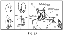
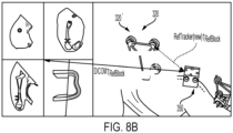
- an implant is designed to include integral registration features such that when the patient is moved, registration can be performed in relation to the implant for the execution of particular operations relative thereto.
- a registration block may be used in conjunction with a reference tracker so that, should the reference tracker be moved relative to the bone, the registration block can be used for reregistration thereby significantly reducing the time, complication, and possible errors that can occur by performing the entire registration process over from the beginning.
- registration builds up a chain of matrix transformations. If that chain of transformations is broken, such as through inadvertent movement of the reference tracker, for example, the broken link in that chain can be repaired by using a registration block rather than reconstructing the chain all over again from scratch.
- a location of the apex of the probe tip within an intraoperative coordinate space is detected at any given time by the localizer and communicated to the processor.
- the outer surface of the probe tip and inner surface of each of the indentations are configured such that, when the probe tip is fully received in any one of the indentations, the apex of the probe tip engages the apex of the indentation such that the locations of the probe tip and indentation are coincident.
- a registration system in a second embodiment, includes a probe and an implant connectable to a bone.
- the probe has a probe body and a first array of markers connected to the probe body, each of the markers being detectable by a localizer, i.e., a localizer of a surgical navigation system.
- the probe also includes a probe tip disposed at an end of the probe body, the probe tip having an apex, a central axis extending through the apex, and an outer surface extending away from the apex.
- the implant has an exterior surface with a plurality of indentations extending therein, each of the indentations having an apex, a central axis extending through the apex of the indentation, and an inner surface extending away from the apex of the indentation. Further, the outer surface of the probe tip and inner surface of each of the indentations are configured such that, when the probe tip is fully received in any one of the indentations, the apex of the probe tip engages the apex of the indentation such that a location of each apex is coincident.
- the registration system of the second embodiment may be configured such that the outer surface of the probe tip has a convex curvature defining a first radius of curvature extending from the central axis of the probe tip to the outer surface.
- the inner surface of each of the indentations may have a concave curvature defining a second radius of curvature extending from the central axis of the indention to the inner surface, the second radius of curvature being equal to the first radius of curvature.
- the first radius of curvature may be 1 mm.
- the registration system may optionally be configured such that the inner surface of each of the indentations is a surface of revolution extending symmetrically about the central axis of the indentation. In such a configuration, the inner surface may be spherical or conical. Alternatively, the inner surface may include a spherical portion extending from the apex and a conical portion extending from the spherical portion.
- the first registration transformation of the first embodiment may be a function of the first position of the reference tracker and the first position of the bone.
- the second registration transformation of the first embodiment may be a function of the first positions of the reference tracker, bone, and implant.
- the method of the first embodiment may include a step of determining a second position of the bone relative to the second position of the reference tracker within the second intraoperative coordinate system based on the first positions of the bone and the implant relative to the first position of the reference tracker and the second position of the implant relative to the second position of reference tracker.
- the implant of the first embodiment may include a bone facing side and a registration side, the registration side having a plurality of indentations extending therein.
- the digitizing step of the first embodiment may include detecting an array of markers connected to the reference tracker via a localizer of the surgical navigation system and touching a plurality of points on the bone and the plurality of indentations via a probe of the surgical navigation system.
- the positioning step may include connecting the implant to the bone in a rigidly fixed relationship thereto.
- determining the second position of the implant may include digitizing the implant within the second intraoperative coordinate system.
- a robotic or computer assisted surgical procedure includes: connecting a reference tracker to a bone at a first position relative thereto; registering a first position of the reference tracker and a position of the bone to a pre-operative coordinate system of a surgical navigation system; preparing the bone according to a pre-operative plan; moving the reference tracker to a second position relative to the bone; placing an implant against the bone so that an opening of the implant defines a first cutting location; registering the second position of the reference tracker and a position of the implant to the pre-operative coordinate system; and cutting the bone at the first cutting location based on the registered position of the implant and the second position of the reference tracker.
- a robotic or computer assisted surgical procedure includes: connecting a reference tracker to a bone; connecting a reference block to the bone; registering the reference tracker, bone, and reference block to a virtual coordinate space of a surgical navigation system based on coordinates of the bone and reference block relative to the reference tracker; and when the reference tracker is moved relative to the bone, re-registering the reference block, reference tracker, and bone to the virtual coordinate space based on coordinates of the bone and reference tracker relative to the reference block.
- the procedure of the second embodiment may include determining a chain of transformations that includes a first registration transformation based on coordinates of the reference tracker.
- the re-registering step of the second embodiment may include determining a chain of transformations that includes a second registration transformation based on coordinates of the reference block.
- Second side 13 also includes a plurality of registration features or registration indentations 20 extending into the one or more exterior surfaces 16.
- Registration features 20 allows implant 10 to be registered directly by a surgical navigation system so that drilling trajectories (or other paths) can be defined directly relative to implant 10.
- registration features 20 are located on an exterior of implant 10 and are compatible with a surgical navigation system to facilitate recognition by the surgical navigation system so that a location and orientation of implant 10 can be determined, and surgical operations can be performed on the bone based on the implant's location and orientation.
- at least three registration features 20 are provided on an exterior of implant 10, although more than three is contemplated and, in some instances, may be preferable.
- Implant 10 is a patient-specific bone plate configured for augmenting a bone void formed from the removal of a bone tumor.
- implant 10 includes a first portion or first plate member 12a, a second portion or second plate member 12b, and a third portion or void filling member 12c.
- First and second plate members 12a-b are connected to and extend outwardly from void filling member 12c, and each include at least one bone screw hole 14 extending therethrough and one or more registration features 20 on a respective exterior surface 16a-b thereof.
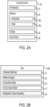
- Data 34b may be retrieved, stored, or modified by the one or more processors 32 in accordance with the instructions 34a.
- the data can be stored in computer registers, in a relational database as a table having many different fields and records, or XML documents.
- the data can also be formatted in any computing device-readable format such as, but not limited to, binary values, ASCII or Unicode.
- the data can comprise any information sufficient to identify the relevant information, such as numbers, descriptive text, proprietary codes, pointers, references to data stored in other memories such as at other network locations, or information that is used by a function to calculate the relevant data.
- such software platform 31 may be configured to convert, via processor 32, the one or more medical image 33 of a patient's bone into virtual bone model 35 so that certain surgical operations can be virtually performed on the virtual bone model 35 and added to the preoperative plan for later use by one or more operative software platforms configured to execute the preoperative plan.
- Such software platform 31 may also be configured to generate or import from a CAD platform, via processor 32, the virtual implant model 35 which may be a patient-specific virtual implant model 10' based on the virtual bone model 35 and modifications thereof via certain surgical operations applied thereto.
- virtual implant model 10' may be based on off-the-shelf implants stored in a database of memory 34 for selection by the user.
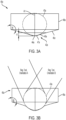
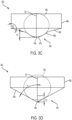
- a third portion 47a of face 42a forms a second arcuate portion, also referred to herein as a rounded nose, that extends from first arcuate portion 46a while having a smaller radius of curvature than first arcuate portion 46a.
- Apex 44a is centered on and intersects nose 47a.
- FIG. 3B depicts a virtual registration feature template 40b according to another embodiment of the present disclosure.
- Registration feature template 40b is similar to template 40a and is therefore accorded like reference numerals to that of template 40a.
- template 40b includes a template body 48a, a template face 42b extending from template body 48b, and an axis A2 extending through an apex 44b of template face 42b.
- a first portion 45b of template face 42b intersects template body 48b at an angle ⁇ 2 which may be equal to angle O1.
- feature template 40b differs in that feature depth Y2 is greater than Y1.
- Y2 may be 0.5 mm.
- first arcuate portion 46a may have a smaller radius of curvature than first arcuate portion 45a of template 40a such that template face 42b has a more bulbous appearance.
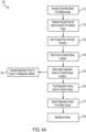
- FIGs. 3A-3D is a block diagram illustrate a method of making implant 10.
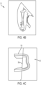
- one or more medical image 33 of a patient's affected anatomy is obtained, which in the exemplary case of the present disclosure is a femur, as shown in FIG. 4B .
- the medical image 33 can be acquired via a variety of medical imaging means, such as magnetic resonance imaging (MRI), computerized tomography (CT), and X-ray, for example.
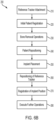
- Software platform 31 may then then generate 110 a virtual bone model 35 from the medical image 33 according to known techniques or import the virtual bone model 35 from another software platform configured to generate the virtual bone model 35.
- MRI magnetic resonance imaging
- CT computerized tomography
- X-ray X-ray
- the virtual bone model 35 is then manipulated in a virtual coordinate space.
- certain surgical operations may be performed on the virtual bone 35 in the virtual coordinate space to develop a preoperative plan 120 to be applied through the aid of a robot and/or computer during the surgical procedure.
- such surgical operations may include applying a resection envelope or resection boundary 118 surrounding a bone segment 35a containing a bone tumor, for example.
- a robot operating a cutting instrument, such as a rotating burr, for example, may follow this resection envelope 118 to remove a correspondingly shaped segment of bone from the patient during the procedure.
- Haptic object 94 is a virtual object used to guide and/or constrain the movement and operations of a working end 96 of surgical tool 92 to a target area inside a patient's anatomy 80, for example the patient's leg.
- haptic object 94 is used to aid the surgeon to target and approach the intended anatomical site of the patient.
- Haptic feedback forces may be used to slow and/or stop the surgical tool's movement if it is detected that a portion of surgical tool 92 will intrude or cross over pre-defined boundaries of the haptic object.
- haptic feedback forces can also be used to attract (or repulse) surgical tool 92 toward (or away from) haptic object 94 and to (or away from) the target.
- surgeon 98 may be presented with a representation of the anatomy being operated on and/or a virtual representation of surgical tool 92 and/or haptic object 94 on display 60.
Landscapes
- Health & Medical Sciences (AREA)
- Life Sciences & Earth Sciences (AREA)
- Surgery (AREA)
- Engineering & Computer Science (AREA)
- Orthopedic Medicine & Surgery (AREA)
- Heart & Thoracic Surgery (AREA)
- Nuclear Medicine, Radiotherapy & Molecular Imaging (AREA)
- Biomedical Technology (AREA)
- Medical Informatics (AREA)
- Molecular Biology (AREA)
- Animal Behavior & Ethology (AREA)
- General Health & Medical Sciences (AREA)
- Public Health (AREA)
- Veterinary Medicine (AREA)
- Robotics (AREA)
- Neurology (AREA)
- Surgical Instruments (AREA)
Applications Claiming Priority (1)
| Application Number | Priority Date | Filing Date | Title |
|---|---|---|---|
| US202363478420P | 2023-01-04 | 2023-01-04 |
Publications (2)
| Publication Number | Publication Date |
|---|---|
| EP4397271A1 true EP4397271A1 (de) | 2024-07-10 |
| EP4397271B1 EP4397271B1 (de) | 2025-09-24 |
Family
ID=89474775
Family Applications (1)
| Application Number | Title | Priority Date | Filing Date |
|---|---|---|---|
| EP24150155.0A Active EP4397271B1 (de) | 2023-01-04 | 2024-01-03 | Patientenneuregistrierungssysteme |
Country Status (3)
| Country | Link |
|---|---|
| US (1) | US20240216083A1 (de) |
| EP (1) | EP4397271B1 (de) |
| AU (1) | AU2024200049A1 (de) |
Families Citing this family (1)
| Publication number | Priority date | Publication date | Assignee | Title |
|---|---|---|---|---|
| US20250032133A1 (en) * | 2023-07-24 | 2025-01-30 | Orthosoft Ulc | Computer-assisted navigation of lock hole in implant |
Citations (5)
| Publication number | Priority date | Publication date | Assignee | Title |
|---|---|---|---|---|
| US7831292B2 (en) | 2002-03-06 | 2010-11-09 | Mako Surgical Corp. | Guidance system and method for surgical procedures with improved feedback |
| US20170252169A1 (en) * | 2014-11-24 | 2017-09-07 | The Johns Hopkins University | A cutting machine for resizing raw implants during surgery |
| US20180263714A1 (en) * | 2017-03-16 | 2018-09-20 | KB Medical SA | Robotic navigation of robotic surgical systems |
| WO2021207471A1 (en) * | 2020-04-08 | 2021-10-14 | Think Surgical, Inc. | Digitizer calibration check |
| WO2021243241A1 (en) * | 2020-05-29 | 2021-12-02 | Materialise N.V. | Implant for correcting a defect of a bone structure with navigation fiducials |
-
2024
- 2024-01-03 US US18/402,914 patent/US20240216083A1/en active Pending
- 2024-01-03 EP EP24150155.0A patent/EP4397271B1/de active Active
- 2024-01-04 AU AU2024200049A patent/AU2024200049A1/en active Pending
Patent Citations (5)
| Publication number | Priority date | Publication date | Assignee | Title |
|---|---|---|---|---|
| US7831292B2 (en) | 2002-03-06 | 2010-11-09 | Mako Surgical Corp. | Guidance system and method for surgical procedures with improved feedback |
| US20170252169A1 (en) * | 2014-11-24 | 2017-09-07 | The Johns Hopkins University | A cutting machine for resizing raw implants during surgery |
| US20180263714A1 (en) * | 2017-03-16 | 2018-09-20 | KB Medical SA | Robotic navigation of robotic surgical systems |
| WO2021207471A1 (en) * | 2020-04-08 | 2021-10-14 | Think Surgical, Inc. | Digitizer calibration check |
| WO2021243241A1 (en) * | 2020-05-29 | 2021-12-02 | Materialise N.V. | Implant for correcting a defect of a bone structure with navigation fiducials |
Non-Patent Citations (1)
| Title |
|---|
| ELVIS C. S. CHEN: "Contact-less stylus for surgical navigation: registration without digitization", vol. 12, no. 7, 6 April 2017 (2017-04-06), DE, pages 1231 - 1241, XP093159100, ISSN: 1861-6410, Retrieved from the Internet <URL:https://link.springer.com/content/pdf/10.1007/s11548-017-1576-7.pdf> DOI: 10.1007/s11548-017-1576-7 * |
Also Published As
| Publication number | Publication date |
|---|---|
| US20240216083A1 (en) | 2024-07-04 |
| EP4397271B1 (de) | 2025-09-24 |
| AU2024200049A1 (en) | 2024-07-18 |
Similar Documents
| Publication | Publication Date | Title |
|---|---|---|
| CN111388087B (zh) | 手术导航系统及执行手术导航方法的计算机与存储介质 | |
| US20230021298A9 (en) | Surgical robot platform | |
| EP1697874B1 (de) | Computerunterstützte Knieersatzvorrichtung | |
| CA2651782C (en) | System and method for verifying calibration of a surgical device | |
| US20070038223A1 (en) | Computer-assisted knee replacement apparatus and method | |
| US12245954B2 (en) | Robotic system for ankle arthroplasty | |
| US20050267353A1 (en) | Computer-assisted knee replacement apparatus and method | |
| US20140324205A1 (en) | Method of manufacturing an arthroplasty jig | |
| US20060212044A1 (en) | Frameless stereotactic guidance of medical procedures | |
| US11819297B2 (en) | Light guided digitization method to register a bone | |
| CN109788963A (zh) | 用于手术销驱动器的销放置保持器 | |
| US20050267722A1 (en) | Computer-assisted external fixation apparatus and method | |
| US20050267354A1 (en) | System and method for providing computer assistance with spinal fixation procedures | |
| US20210030477A1 (en) | Computer assisted implant placement | |
| US20220071713A1 (en) | Method of verifying tracking array positional accuracy | |
| US20250204993A1 (en) | System and method to check cut plane accuracy after bone removal | |
| AU2025271240A1 (en) | System and method to position a tracking system field-of-view | |
| EP1667574A2 (de) | System und verfahren zur computerunterstützung von wirbelfixationsverfahren | |
| EP4397271B1 (de) | Patientenneuregistrierungssysteme | |
| Nakajima et al. | Surgical tool alignment guidance by drawing two cross-sectional laser-beam planes | |
| KR20230034296A (ko) | 내비게이션 및/또는 로봇 추적 방법 및 시스템 | |
| US12533194B2 (en) | Light guided digitization method to register a bone | |
| US20240390160A1 (en) | System and method for determining if hardware installed in a bone is located within a volume of bone to be removed | |
| US20240173096A1 (en) | System and method for detecting a potential collision between a bone and an end-effector | |
| WO2025006323A1 (en) | Locating features at pre-defined locations relative to a bone cut surface |
Legal Events
| Date | Code | Title | Description |
|---|---|---|---|
| PUAI | Public reference made under article 153(3) epc to a published international application that has entered the european phase |
Free format text: ORIGINAL CODE: 0009012 |
|
| STAA | Information on the status of an ep patent application or granted ep patent |
Free format text: STATUS: REQUEST FOR EXAMINATION WAS MADE |
|
| 17P | Request for examination filed |
Effective date: 20240103 |
|
| AK | Designated contracting states |
Kind code of ref document: A1 Designated state(s): AL AT BE BG CH CY CZ DE DK EE ES FI FR GB GR HR HU IE IS IT LI LT LU LV MC ME MK MT NL NO PL PT RO RS SE SI SK SM TR |
|
| GRAP | Despatch of communication of intention to grant a patent |
Free format text: ORIGINAL CODE: EPIDOSNIGR1 |
|
| STAA | Information on the status of an ep patent application or granted ep patent |
Free format text: STATUS: GRANT OF PATENT IS INTENDED |
|
| INTG | Intention to grant announced |
Effective date: 20250424 |
|
| GRAS | Grant fee paid |
Free format text: ORIGINAL CODE: EPIDOSNIGR3 |
|
| GRAA | (expected) grant |
Free format text: ORIGINAL CODE: 0009210 |
|
| STAA | Information on the status of an ep patent application or granted ep patent |
Free format text: STATUS: THE PATENT HAS BEEN GRANTED |
|
| AK | Designated contracting states |
Kind code of ref document: B1 Designated state(s): AL AT BE BG CH CY CZ DE DK EE ES FI FR GB GR HR HU IE IS IT LI LT LU LV MC ME MK MT NL NO PL PT RO RS SE SI SK SM TR |
|
| P01 | Opt-out of the competence of the unified patent court (upc) registered |
Free format text: CASE NUMBER: UPC_APP_3355_4397271/2025 Effective date: 20250814 |
|
| REG | Reference to a national code |
Ref country code: GB Ref legal event code: FG4D |
|
| REG | Reference to a national code |
Ref country code: CH Ref legal event code: EP |
|
| REG | Reference to a national code |
Ref country code: DE Ref legal event code: R096 Ref document number: 602024000700 Country of ref document: DE |
|
| REG | Reference to a national code |
Ref country code: IE Ref legal event code: FG4D |
|
| PG25 | Lapsed in a contracting state [announced via postgrant information from national office to epo] |
Ref country code: NO Free format text: LAPSE BECAUSE OF FAILURE TO SUBMIT A TRANSLATION OF THE DESCRIPTION OR TO PAY THE FEE WITHIN THE PRESCRIBED TIME-LIMIT Effective date: 20251224 |
|
| REG | Reference to a national code |
Ref country code: LT Ref legal event code: MG9D |
|
| PG25 | Lapsed in a contracting state [announced via postgrant information from national office to epo] |
Ref country code: FI Free format text: LAPSE BECAUSE OF FAILURE TO SUBMIT A TRANSLATION OF THE DESCRIPTION OR TO PAY THE FEE WITHIN THE PRESCRIBED TIME-LIMIT Effective date: 20250924 |
|
| PG25 | Lapsed in a contracting state [announced via postgrant information from national office to epo] |
Ref country code: HR Free format text: LAPSE BECAUSE OF FAILURE TO SUBMIT A TRANSLATION OF THE DESCRIPTION OR TO PAY THE FEE WITHIN THE PRESCRIBED TIME-LIMIT Effective date: 20250924 |
|
| PGFP | Annual fee paid to national office [announced via postgrant information from national office to epo] |
Ref country code: FR Payment date: 20251208 Year of fee payment: 3 |
|
| PG25 | Lapsed in a contracting state [announced via postgrant information from national office to epo] |
Ref country code: GR Free format text: LAPSE BECAUSE OF FAILURE TO SUBMIT A TRANSLATION OF THE DESCRIPTION OR TO PAY THE FEE WITHIN THE PRESCRIBED TIME-LIMIT Effective date: 20251225 |
|
| PG25 | Lapsed in a contracting state [announced via postgrant information from national office to epo] |
Ref country code: SE Free format text: LAPSE BECAUSE OF FAILURE TO SUBMIT A TRANSLATION OF THE DESCRIPTION OR TO PAY THE FEE WITHIN THE PRESCRIBED TIME-LIMIT Effective date: 20250924 |
|
| PGFP | Annual fee paid to national office [announced via postgrant information from national office to epo] |
Ref country code: IE Payment date: 20251209 Year of fee payment: 3 |
|
| PG25 | Lapsed in a contracting state [announced via postgrant information from national office to epo] |
Ref country code: LV Free format text: LAPSE BECAUSE OF FAILURE TO SUBMIT A TRANSLATION OF THE DESCRIPTION OR TO PAY THE FEE WITHIN THE PRESCRIBED TIME-LIMIT Effective date: 20250924 |
|
| PG25 | Lapsed in a contracting state [announced via postgrant information from national office to epo] |
Ref country code: BG Free format text: LAPSE BECAUSE OF FAILURE TO SUBMIT A TRANSLATION OF THE DESCRIPTION OR TO PAY THE FEE WITHIN THE PRESCRIBED TIME-LIMIT Effective date: 20250924 |
|
| PG25 | Lapsed in a contracting state [announced via postgrant information from national office to epo] |
Ref country code: RS Free format text: LAPSE BECAUSE OF FAILURE TO SUBMIT A TRANSLATION OF THE DESCRIPTION OR TO PAY THE FEE WITHIN THE PRESCRIBED TIME-LIMIT Effective date: 20251224 |
|
| REG | Reference to a national code |
Ref country code: NL Ref legal event code: MP Effective date: 20250924 |