EP4397224A1 - Button structure, liquid storage tank, and automatic cleaning device - Google Patents
Button structure, liquid storage tank, and automatic cleaning device Download PDFInfo
- Publication number
- EP4397224A1 EP4397224A1 EP22862576.0A EP22862576A EP4397224A1 EP 4397224 A1 EP4397224 A1 EP 4397224A1 EP 22862576 A EP22862576 A EP 22862576A EP 4397224 A1 EP4397224 A1 EP 4397224A1
- Authority
- EP
- European Patent Office
- Prior art keywords
- storage tank
- liquid storage
- automatic cleaning
- cleaning apparatus
- button structure
- Prior art date
- Legal status (The legal status is an assumption and is not a legal conclusion. Google has not performed a legal analysis and makes no representation as to the accuracy of the status listed.)
- Pending
Links
Images


Classifications
-
- A—HUMAN NECESSITIES
- A47—FURNITURE; DOMESTIC ARTICLES OR APPLIANCES; COFFEE MILLS; SPICE MILLS; SUCTION CLEANERS IN GENERAL
- A47L—DOMESTIC WASHING OR CLEANING; SUCTION CLEANERS IN GENERAL
- A47L11/00—Machines for cleaning floors, carpets, furniture, walls, or wall coverings
- A47L11/24—Floor-sweeping machines, motor-driven
-
- A—HUMAN NECESSITIES
- A47—FURNITURE; DOMESTIC ARTICLES OR APPLIANCES; COFFEE MILLS; SPICE MILLS; SUCTION CLEANERS IN GENERAL
- A47L—DOMESTIC WASHING OR CLEANING; SUCTION CLEANERS IN GENERAL
- A47L11/00—Machines for cleaning floors, carpets, furniture, walls, or wall coverings
- A47L11/40—Parts or details of machines not provided for in groups A47L11/02 - A47L11/38, or not restricted to one of these groups, e.g. handles, arrangements of switches, skirts, buffers, levers
- A47L11/408—Means for supplying cleaning or surface treating agents
- A47L11/4083—Liquid supply reservoirs; Preparation of the agents, e.g. mixing devices
-
- A—HUMAN NECESSITIES
- A47—FURNITURE; DOMESTIC ARTICLES OR APPLIANCES; COFFEE MILLS; SPICE MILLS; SUCTION CLEANERS IN GENERAL
- A47L—DOMESTIC WASHING OR CLEANING; SUCTION CLEANERS IN GENERAL
- A47L11/00—Machines for cleaning floors, carpets, furniture, walls, or wall coverings
- A47L11/28—Floor-scrubbing machines, motor-driven
- A47L11/284—Floor-scrubbing machines, motor-driven having reciprocating tools
-
- A—HUMAN NECESSITIES
- A47—FURNITURE; DOMESTIC ARTICLES OR APPLIANCES; COFFEE MILLS; SPICE MILLS; SUCTION CLEANERS IN GENERAL
- A47L—DOMESTIC WASHING OR CLEANING; SUCTION CLEANERS IN GENERAL
- A47L11/00—Machines for cleaning floors, carpets, furniture, walls, or wall coverings
- A47L11/40—Parts or details of machines not provided for in groups A47L11/02 - A47L11/38, or not restricted to one of these groups, e.g. handles, arrangements of switches, skirts, buffers, levers
-
- A—HUMAN NECESSITIES
- A47—FURNITURE; DOMESTIC ARTICLES OR APPLIANCES; COFFEE MILLS; SPICE MILLS; SUCTION CLEANERS IN GENERAL
- A47L—DOMESTIC WASHING OR CLEANING; SUCTION CLEANERS IN GENERAL
- A47L11/00—Machines for cleaning floors, carpets, furniture, walls, or wall coverings
- A47L11/40—Parts or details of machines not provided for in groups A47L11/02 - A47L11/38, or not restricted to one of these groups, e.g. handles, arrangements of switches, skirts, buffers, levers
- A47L11/4002—Installations of electric equipment
-
- A—HUMAN NECESSITIES
- A47—FURNITURE; DOMESTIC ARTICLES OR APPLIANCES; COFFEE MILLS; SPICE MILLS; SUCTION CLEANERS IN GENERAL
- A47L—DOMESTIC WASHING OR CLEANING; SUCTION CLEANERS IN GENERAL
- A47L11/00—Machines for cleaning floors, carpets, furniture, walls, or wall coverings
- A47L11/40—Parts or details of machines not provided for in groups A47L11/02 - A47L11/38, or not restricted to one of these groups, e.g. handles, arrangements of switches, skirts, buffers, levers
- A47L11/4011—Regulation of the cleaning machine by electric means; Control systems and remote control systems therefor
-
- A—HUMAN NECESSITIES
- A47—FURNITURE; DOMESTIC ARTICLES OR APPLIANCES; COFFEE MILLS; SPICE MILLS; SUCTION CLEANERS IN GENERAL
- A47L—DOMESTIC WASHING OR CLEANING; SUCTION CLEANERS IN GENERAL
- A47L11/00—Machines for cleaning floors, carpets, furniture, walls, or wall coverings
- A47L11/40—Parts or details of machines not provided for in groups A47L11/02 - A47L11/38, or not restricted to one of these groups, e.g. handles, arrangements of switches, skirts, buffers, levers
- A47L11/4036—Parts or details of the surface treating tools
-
- A—HUMAN NECESSITIES
- A47—FURNITURE; DOMESTIC ARTICLES OR APPLIANCES; COFFEE MILLS; SPICE MILLS; SUCTION CLEANERS IN GENERAL
- A47L—DOMESTIC WASHING OR CLEANING; SUCTION CLEANERS IN GENERAL
- A47L11/00—Machines for cleaning floors, carpets, furniture, walls, or wall coverings
- A47L11/40—Parts or details of machines not provided for in groups A47L11/02 - A47L11/38, or not restricted to one of these groups, e.g. handles, arrangements of switches, skirts, buffers, levers
- A47L11/4036—Parts or details of the surface treating tools
- A47L11/4041—Roll shaped surface treating tools
-
- A—HUMAN NECESSITIES
- A47—FURNITURE; DOMESTIC ARTICLES OR APPLIANCES; COFFEE MILLS; SPICE MILLS; SUCTION CLEANERS IN GENERAL
- A47L—DOMESTIC WASHING OR CLEANING; SUCTION CLEANERS IN GENERAL
- A47L11/00—Machines for cleaning floors, carpets, furniture, walls, or wall coverings
- A47L11/40—Parts or details of machines not provided for in groups A47L11/02 - A47L11/38, or not restricted to one of these groups, e.g. handles, arrangements of switches, skirts, buffers, levers
- A47L11/4052—Movement of the tools or the like perpendicular to the cleaning surface
- A47L11/4055—Movement of the tools or the like perpendicular to the cleaning surface for lifting the tools to a non-working position
-
- A—HUMAN NECESSITIES
- A47—FURNITURE; DOMESTIC ARTICLES OR APPLIANCES; COFFEE MILLS; SPICE MILLS; SUCTION CLEANERS IN GENERAL
- A47L—DOMESTIC WASHING OR CLEANING; SUCTION CLEANERS IN GENERAL
- A47L11/00—Machines for cleaning floors, carpets, furniture, walls, or wall coverings
- A47L11/40—Parts or details of machines not provided for in groups A47L11/02 - A47L11/38, or not restricted to one of these groups, e.g. handles, arrangements of switches, skirts, buffers, levers
- A47L11/4061—Steering means; Means for avoiding obstacles; Details related to the place where the driver is accommodated
-
- A—HUMAN NECESSITIES
- A47—FURNITURE; DOMESTIC ARTICLES OR APPLIANCES; COFFEE MILLS; SPICE MILLS; SUCTION CLEANERS IN GENERAL
- A47L—DOMESTIC WASHING OR CLEANING; SUCTION CLEANERS IN GENERAL
- A47L11/00—Machines for cleaning floors, carpets, furniture, walls, or wall coverings
- A47L11/40—Parts or details of machines not provided for in groups A47L11/02 - A47L11/38, or not restricted to one of these groups, e.g. handles, arrangements of switches, skirts, buffers, levers
- A47L11/4063—Driving means; Transmission means therefor
- A47L11/4069—Driving or transmission means for the cleaning tools
-
- A—HUMAN NECESSITIES
- A47—FURNITURE; DOMESTIC ARTICLES OR APPLIANCES; COFFEE MILLS; SPICE MILLS; SUCTION CLEANERS IN GENERAL
- A47L—DOMESTIC WASHING OR CLEANING; SUCTION CLEANERS IN GENERAL
- A47L11/00—Machines for cleaning floors, carpets, furniture, walls, or wall coverings
- A47L11/40—Parts or details of machines not provided for in groups A47L11/02 - A47L11/38, or not restricted to one of these groups, e.g. handles, arrangements of switches, skirts, buffers, levers
- A47L11/408—Means for supplying cleaning or surface treating agents
- A47L11/4088—Supply pumps; Spraying devices; Supply conduits
-
- A—HUMAN NECESSITIES
- A47—FURNITURE; DOMESTIC ARTICLES OR APPLIANCES; COFFEE MILLS; SPICE MILLS; SUCTION CLEANERS IN GENERAL
- A47L—DOMESTIC WASHING OR CLEANING; SUCTION CLEANERS IN GENERAL
- A47L2201/00—Robotic cleaning machines, i.e. with automatic control of the travelling movement or the cleaning operation
- A47L2201/02—Docking stations; Docking operations
- A47L2201/026—Refilling cleaning liquid containers
-
- A—HUMAN NECESSITIES
- A47—FURNITURE; DOMESTIC ARTICLES OR APPLIANCES; COFFEE MILLS; SPICE MILLS; SUCTION CLEANERS IN GENERAL
- A47L—DOMESTIC WASHING OR CLEANING; SUCTION CLEANERS IN GENERAL
- A47L2201/00—Robotic cleaning machines, i.e. with automatic control of the travelling movement or the cleaning operation
- A47L2201/06—Control of the cleaning action for autonomous devices; Automatic detection of the surface condition before, during or after cleaning
Definitions
- Objectives of the present disclosure are to provide a button structure, a liquid storage tank and an automatic cleaning apparatus, which can solve the technical problem of inconvenience in disassembly of the liquid storage tank.
- the present disclosure provides a liquid storage tank, which includes the button structure according to the above aspect.
- the tab included an inclined surface configured to be clamped with the boss in response to the tab abutting the boss.
- the motor 4211 is connected to the driving wheel 4212, the vibrating member 4213, the connecting rod 4214 and a vibration buffering device 4215 through the power transmission device.
- the vibrating member 4213 and the connecting rod 4214 constitute an approximate L-shaped structure, as shown in FIG. 6 .
- the vibrating member 4213 reciprocates under the driving of the connecting rod 4214.
- the vibration buffering device 4215 has functions of damping and reducing the shaking of a motion behavior driven by the driving wheel 4212, so that the vibrating member 4213 may vibrate stably within a range of motion provided by the supporting platform 422.
- the vibration buffering device 4215 is made of a soft material, optionally a rubber structure, and the vibration buffering device 4215 is sleeved on the connecting rod 4214.
- the vibration buffering device 4215 may also protect the vibrating member 4213 from being damaged due to the collision with the driving platform 421, and thus may also affect the reciprocating motion of the vibrating member 4213.
- Movable components and fixed components of the driving platform 421 are restricted from moving in the travelling direction of the automatic cleaning apparatus through connections with less elasticity, and are connected flexibly and allowed to move in the direction substantially perpendicular to the travelling direction, that is, in a vibration direction of the vibrating member 4213. The above two movement restrictions cause the vibrating member 4213 to substantially reciprocate rather than accurately reciprocate.
- the cleaning intensity/efficiency of the automatic cleaning apparatus may also be automatically and dynamically adjusted according to an operation environment of the automatic cleaning apparatus.
- the automatic cleaning apparatus may achieve dynamic adjustment according to physical information of the surface to be cleaned detected by the perception system 120.
- the perception system 120 may detect the flatness of the surface to be cleaned, a material of the surface to be cleaned, the existence of oil and dust, and other information, and transmit the information to the control system 130 of the automatic cleaning apparatus.
- the control system 130 may instruct the automatic cleaning apparatus to automatically and dynamically adjust a rotational speed of the motor and a transmission ratio of the power transmission device according to the operation environment of the automatic cleaning apparatus, so as to adjust a preset reciprocating period of the reciprocating motion of the cleaning head 410.
- the preset reciprocating period when the automatic cleaning apparatus operates on a flat ground, the preset reciprocating period may be automatically and dynamically adjusted to be longer, and a water volume of the water pump may be automatically and dynamically adjusted to be smaller; and when the automatic cleaning apparatus operates on a less flat ground, the preset reciprocating period may be automatically and dynamically adjusted to be shorter, and the water volume of the water pump may be automatically and dynamically adjusted to be larger. This is because it is easier to clean the flat ground than the less flat ground, and thus the reciprocating motion of the cleaning head 410 at a higher speed (i.e., a higher frequency) and in the larger water volume are needed for cleaning an uneven ground.
- a higher speed i.e., a higher frequency
- the preset reciprocating period when the automatic cleaning apparatus operates on a table, the preset reciprocating period may be automatically and dynamically adjusted to be longer, and the water volume of the water pump may be automatically and dynamically adjusted to be smaller; and when the automatic cleaning apparatus 100 operates on a ground, the preset reciprocating period may be automatically and dynamically adjusted to be shorter, and the water volume of the water pump may be automatically and dynamically adjusted to be larger.
- the table has less dust and oil compared to the ground, the material of the table is also easier to be cleaned, and thus, the table can be cleaned with the fewer number of reciprocating motions of the cleaning head 410 and the relatively smaller water volume of the water pump.
- the cleaning head 410 includes a movable region 412 connected to the cleaning substrate 4221 to substantially reciprocate along the surface to be cleaned under the driving of the cleaning substrate 4221.
- the movable region 412 is disposed at a substantially central position of the cleaning head 410.
- an adhesive layer is provided on a side of the movable region 412 connected to the cleaning substrate 4221, and the movable region 412 is connected to the cleaning substrate 4221 through the adhesive layer.
- the cleaning head 410 further includes a fixed region 411 connected to a bottom of the supporting platform 422 through the at least one assembly region 4224.
- the fixed region 411 cleans at least a part of the operating surface along with the movement of the supporting platform 422.
- the cleaning head 410 further includes a flexible connecting portion 413 disposed between the fixed region 411 and the movable region 412 for connecting the fixed region 411 and the movable region 412.
- the cleaning head 410 further includes a sliding fastener 414 extending along an edge of the cleaning head 410 and detachably mounted at an engagement position 4225 of the supporting platform 422.
- the cleaning head 410 may be made of a material with certain elasticity, and is fixed to the surface of the supporting platform 422 through the adhesive layer so as to reciprocate. The cleaning head 410 is always in contact with the surface to be cleaned during operation.
- the water delivery mechanism includes a water discharging device 4217 that may be directly or indirectly connected to a cleaning liquid outlet of a liquid storage tank (not shown), that is, a liquid outlet of the clean water storage tank.
- the cleaning liquid may flow to the water discharging device 4217 via the cleaning liquid outlet of the liquid storage tank, and may be evenly coated on the surface to be cleaned through the water discharging device.
- a connecting member (not shown) may be provided on the water discharging device, and the water discharging device is connected to the cleaning liquid outlet of the liquid storage tank through the connecting member.
- the water discharging device is provided with a distribution port which may be a continuous opening or a combination of several discontinuous small openings, and several nozzles may be provided at the distribution port.
- the cleaning liquid flows to the distribution port via the cleaning liquid outlet of the liquid storage tank and the connecting member of the water discharging device, and is evenly coated on the operating surface via the distribution port.
- the clean water pump 4219 may be connected to the connecting member of the water discharging device, and configured to pump the cleaning liquid from the liquid storage tank to the water discharging device.
- the clean water pump may be a gear pump, a vane pump, a plunger pump, a peristaltic pump, or the like.
- the water delivery mechanism draws the cleaning liquid out of the clean water storage tank through the clean water pump 4219 and the clean water pump pipe 4218, and transports the cleaning liquid to the water discharging device.
- the water discharging device 4217 may be a sprinkler head, a drip hole, a wet cloth, or the like, and may uniformly spread water on the cleaning head so as to wet the cleaning head and the surface to be cleaned. Stains on the wetted surface to be cleaned can be cleaned more easily.
- the power/flow rate of the clean water pump may be adjusted.
- the motor 4211 drives a cable gear 42196 to rotate through the gear set 42193.
- a cable 42194 is wound on the cable gear 42196, and is wound and suspended on the driving platform 421, and the cable gear 42196 pulls the cable 42196 to rise and drop so as to lift and lower the driving platform 421.
- the cable gear 42196 and the cable 42194 are core components of the lifting and lowering module.
- a clutch 42195 is disposed on the gear set 42193 and the cable gear 42196.
- the clutch 42195 includes a spring and a sheet-like member.
- the motor 4211 controls three motion modules, the motor 4211 rotates in one direction to drive the vibrating member to vibrate and enable the clean water pump 4219 to supply water simultaneously; and rotates in an opposite direction to drive the lifting and lowering module to lift and lower through the cable 42194.
- the combined design of the gear set realizes the control of the three motion modules in different combinations, for example, rotating the clean water pump in one direction to supply water, and rotating in the opposite direction to control the lifting and lowering and vibration.
- two motors may also be used to control the three motion modules, but an extra motor also increases the cost.
- the lifting and lowering module In cooperation with a surface medium sensor and other sensors that can detect a surface type of the surface to be cleaned, the lifting and lowering module enables the wet cleaning module to perform a cleaning operation according to different surfaces to be cleaned. For example, the lifting and lowering module lifts the wet cleaning module in case of a carpet surface, and lowers the wet cleaning module in case of a floor surface, a floor tile surface or the like, for cleaning. Thus, a more comprehensive cleaning effect is achieved.
- a second assembling portion 3004 is disposed on the liquid storage tank 3000 and connected to the base station, such that the base station may fill the cleaning liquid into the liquid storage tank 3000 of the automatic cleaning apparatus 10 through the liquid replenishing port 3005.
- the second assembling portion 3004 further includes the liquid replenishing port 3005, which is located at an approximately central position of the second assembling portion 3004 and configured to fill the cleaning liquid to the liquid storage tank 3000.
- a valve 17 is disposed on the liquid replenishing port 3005 of the liquid storage tank 3000, and the valve 17 may be opened and closed to control the communication and disconnection between the liquid replenishing port 3005 and the liquid storage tank 3000.
- a pipeline 18 is disposed in the liquid storage tank 3000, and the valve 17 is disposed at one end of the pipeline 18.
- the valve 17 may be an electronic valve or a manual valve. Thus, it is ensured that the valve is opened and closed through the corresponding control. In other embodiments of the present disclosure, the valve 17 may also be a check valve. After liquid supplement of the liquid storage tank 3000 is completed and the liquid replenishing port 3005 is disconnected from the liquid storage tank 3000, the valve 17 is automatically closed, thereby preventing the cleaning liquid in the liquid storage tank 3000 from flowing out.
- the valve 17 may be a cross valve, a lift check valve, a swing check valve, etc.
- the automatic cleaning apparatus 10 includes a liquid storage tank assembling structure 4000; the liquid storage tank 3000 includes a notch portion 3006 matching the liquid storage tank assembling structure 4000; and the liquid storage tank assembling structure 4000 is assembled in the notch portion 3006 when the liquid storage tank 3000 is assembled on the automatic cleaning apparatus 10, thereby realizing complete match.
- the liquid storage tank assembling structure 4000 includes a tab 4001 which is configured to abut and then be clamped with the boss 2002 of the button structure 12.
- the liquid storage tank assembling structure 4000 further includes a second elastic member 4004 which provides an elastic force in a vertical direction, such that the tab 4001 is movable telescopically in the vertical direction.
- the second elastic member 4004 and the tab 4001 may be located within a same slide channel to achieve the telescopic movement described above.
- the second elastic member 4004 is, for example, a coil spring.
- the tab 4001 includes an inclined surface 4002 which, after the tab 4001 abuts the boss, is matched and then clamped with an inclined surface of the boss.
- the tab 4001 further includes a vertical surface 4003 which, when the liquid storage tank is assembled on the automatic cleaning apparatus, is clamped with an inner surface of a groove 3002.
- the inclined surface 4002 and the vertical surface 4003 can ensure that the liquid storage tank 3000 is accurately positioned forward and backward after being installed on the automatic cleaning apparatus, thereby avoiding looseness in any direction.
- the liquid storage tank 3000 includes a first assembling portion 3001.
- the first assembling portion 3001 is located at the approximately central position of the liquid storage tank 3000.
- the first assembling portion 3001 may be rectangular, circular and other structures, which are not limited.
- the first assembling portion 3001 further includes a button structure 12, a groove 3002 and a light transmission port 3003.
- the groove 3002 is located at the bottom of the first assembling portion 3001 and is sunken downward to form a shape matching the button structure 12. When the button structure 12 is assembled on the liquid storage tank 3000, the groove 3002 is configured to accommodate the button structure 12.
- the boss 2002 includes: a first surface 20021, which is a curved surface extending upward along an upper surface of the button body 2000; a second surface 20022, which is a curved surface in smooth connection with the first surface 20021, and configured to abut and then be clamped with the tab of the automatic cleaning apparatus; and a third surface 20023, which is a plane that is in smooth connection with the second surface 20022 and then extends in a substantially vertical direction.
- the third surface may be fitted to the plane of the inner surface of the groove, and stable clamping of three planes can be realized in combination with the plane of the tab.
- the second surface 20022 may be formed in a recessed multi-radian curved surface, and is used to match an end and an inclined surface of the tab, thereby achieving stable clamping.
- a connecting portion between the first surface 20021 and the second surface 20022 is higher than a connecting portion between the second surface 20022 and the third surface 20023.
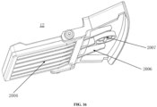
- the button structure further includes: lugs 2003, which are symmetrically disposed on both sides of the button body 2000; and a rotating shaft 2004, which is configured to connect the lugs 2003 and the liquid storage tank, such that the button structure is rotatable around the rotating shaft 2004.
- the rotating shaft 2004 may be disposed closer to the pressing portion 2001. In this way, when the button structure realizes a seesaw movement through the rotating shaft, the boss has a longer movable stroke than the pressing portion, so that the tab is easily jacked up through the boss, and thus the liquid storage tank may be disassembled more easily.
- an upper surface of the pressing portion 2001 is higher than an upper surface of the button body 2000, and the lower surface of the pressing portion 2001 is higher than a lower surface of the button body 2000. Therefore, more movable space can be provided for the pressing portion 2001 to ensure the movable stroke of the pressing portion 2001, thereby facilitating the disassembly of the liquid storage tank.
- the lower surface of the pressing portion 2001 includes a plurality of reinforcing ribs, and/or, the lower surface of the button body 2000 includes a plurality of reinforcing ribs, so as to increase the rigidity of the button structure while reducing the weight of the entire button structure.
- the pressing portion When the liquid storage tank needs to be removed, the pressing portion is pressed, the boss is lifted up under the action of the rotating shaft and the tab is jacked. At this time, the rear end of the tab is no longer in contact with the side wall of the groove, such that the liquid storage tank can be removed.
- the first assembling portion 3001 further includes a light transmission port 3003, which is located above the button structure 12 and matches a return pile lamp on the automatic cleaning apparatus in position.
- the return pile lamp performs emission through the light transmission port 3003 to realize communication with a charging pile.
Landscapes
- Cleaning By Liquid Or Steam (AREA)
Abstract
Description
- The present application claims priority to
Chinese Patent Application No. 202111021326.9, filed on September 1, 2021 - The present disclosure relates to the field of cleaning robot technologies, and particularly to a button structure, a liquid storage tank and an automatic cleaning apparatus.
- Automatic cleaning apparatuses are used to automatically clean designated places. The existing automatic cleaning apparatuses include ground sweeping machines, ground mopping machines, sweeping and mopping integrated machines, etc. The automatic cleaning apparatus capable of mopping the ground is equipped a liquid storage tank to provide a liquid for cleaning.
- A water tank is usually detachable, thereby being convenient for cleaning, maintenance, water filling and other operations of the water tank. For the detachable water tank, it is necessary to design different detaching buttons according to different water tank structures and automatic cleaning apparatus structures. The existing detaching buttons are either not convenient for disassembly of the water tank, or too large in volume, which adversely affects the installation of other components of the automatic cleaning apparatus and the volume of the water tank, thereby bringing inconvenience to the disassembly of the water tank.
- Objectives of the present disclosure are to provide a button structure, a liquid storage tank and an automatic cleaning apparatus, which can solve the technical problem of inconvenience in disassembly of the liquid storage tank.
- According to some embodiments of the present disclosure, in an aspect, the present disclosure provides a button structure, which is assembled on a liquid storage tank and configured to allow the liquid storage tank to be detachably assembled on an automatic cleaning apparatus. The button structure includes: a button body; a pressing portion, located at one end of the button body and configured to unlock the liquid storage tank from the automatic cleaning apparatus in response to a downward acting force; and a boss, located at another end of the button body opposite to the pressing portion, wherein when the button structure is assembled on the liquid storage tank, the pressing portion is higher than the boss, and the boss moves in a direction opposite to a movement direction of the pressing portion, thereby causing the liquid storage tank to be detachably assembled on the automatic cleaning apparatus.
- In an embodiment of the present disclosure, the boss includes: a first surface, formed as a curved surface extending upward along an upper surface of the button body; a second surface, formed as a curved surface in smooth connection with the first surface and configured to abut and be clamped with a tab of the automatic cleaning apparatus; and a third surface, formed as a plane in smooth connection with the second surface and configured to extend in a substantially vertical direction.
- In an embodiment of the present disclosure, a connecting portion between the first surface and the second surface is higher than a connecting portion between the second surface and the third surface.
- In an embodiment of the present disclosure, the button structure further includes: lugs, symmetrically disposed on both sides of the button body; and a rotating shaft, configured to connect the lugs and the liquid storage tank, thereby enabling the button structure to be rotatable around the rotating shaft.
- In an embodiment of the present disclosure, the button structure further includes: a first elastic member, disposed on a lower surface of the pressing portion, and configured to provide a restoring force to the pressing portion in response to releasing of the acting force applied to the pressing portion.
- In an embodiment of the present disclosure, an upper surface of the pressing portion is higher than an upper surface of the button body, and a lower surface of the pressing portion is higher than a lower surface of the button body.
- In an embodiment of the present disclosure, the lower surface of the pressing portion is provided with a plurality of reinforcing ribs, and/or, the lower surface of the button body is provided with a plurality of reinforcing ribs.
- According to some embodiments of the present disclosure, in another aspect, the present disclosure provides a liquid storage tank, which includes the button structure according to the above aspect.
- In an embodiment of the present disclosure, the liquid storage tank further includes a first assembling portion, located at an approximately central position of the liquid storage tank and configured for assembly of the button structure.
- In an embodiment of the present disclosure, the first assembling portion includes a groove configured to accommodate the button structure in response to the assembly of the button structure on the liquid storage tank.
- In an embodiment of the present disclosure, the first assembling portion further includes a light transmission port, located above the button structure and positionally matches a return pile lamp on the automatic cleaning apparatus.
- In an embodiment of the present disclosure, the liquid storage tank further includes a second assembling portion, located at an approximately central position of the liquid storage tank and configured to fill a cleaning liquid to the liquid storage tank after being connected with a base station.
- In an embodiment of the present disclosure, the second assembling portion further includes a liquid replenishing port, located at an approximately central position of the second assembling portion and configured to fill a cleaning liquid to the liquid storage tank.
- According to some embodiments of the present disclosure, in a further aspect, the present disclosure provides an automatic cleaning apparatus, which includes the liquid storage tank according to the above aspect.
- In an embodiment of the present disclosure, the automatic cleaning apparatus further includes a liquid storage tank assembling structure; the liquid storage tank includes a notch portion matching the liquid storage tank assembling structure, and the liquid storage tank assembling structure is configured to be assembled in the notch portion in response to assembly of the liquid storage tank on the automatic cleaning apparatus.
- In an embodiment of the present disclosure, the liquid storage tank assembling structure includes a tab configured to abut and be clamped with the boss.
- In an embodiment of the present disclosure, the tab included an inclined surface configured to be clamped with the boss in response to the tab abutting the boss.
- In an embodiment of the present disclosure, the liquid storage tank assembling structure further includes a second elastic member configured to allow the tab to move telescopically in a vertical direction.
- In an embodiment of the present disclosure, the liquid storage tank further includes a groove configured to be clamped with the tab in response to the assembly of the liquid storage tank on the automatic cleaning apparatus.
- In an embodiment of the present disclosure, the tab further includes a vertical surface configured to be clamped with an inner surface of the groove in response to the assembly of the liquid storage tank on the automatic cleaning apparatus.
- According to the button structure, the liquid storage tank and the automatic cleaning apparatus provided by the present disclosure, the button structure is of a thin sheet structure, thereby facilitating disassembly of the liquid storage tank while occupying a small volume. In addition, the button structure can realize a seesaw-type movement, and is in elastic cooperation with the tab of the automatic cleaning apparatus, thereby realizing high convenience in disassembly and avoiding the phenomenon of getting stuck.
- The drawings herein are incorporated into the description and constitute a part of the description, show embodiments that are consistent with the present disclosure, and are used together with the description to explain the principles of the present disclosure. Understandably, the accompanying drawings in the following description show merely some embodiments of the present disclosure, and a person of ordinary skill in the art may still derive other drawings from these accompanying drawings without creative efforts. In the drawings:
-
FIG. 1 is an oblique view of an automatic cleaning apparatus according to an embodiment of the present disclosure; -
FIG. 2 is a schematic diagram of a bottom structure of the automatic cleaning apparatus according to an embodiment of the present disclosure; -
FIG. 3 is an exploded view of an automatic cleaning apparatus according to an embodiment of the present disclosure; -
FIG. 4 is a structural diagram of a supporting platform of an automatic cleaning apparatus according to an embodiment of the present disclosure; -
FIG. 5 is a structural diagram of a vibrating member of an automatic cleaning apparatus according to an embodiment of the present disclosure; -
FIG. 6 is a structural diagram of a vibrating member according to an embodiment of the present disclosure; -
FIG. 7 is a schematic structural diagram of the assembly of a cleaning substrate according to an embodiment of the present disclosure; -
FIG. 8 is a structural diagram of a clean water pump driven by a motor according to an embodiment of the present disclosure; -
FIG. 9 is a structural diagram of a lifting and lowering module driven by a motor according to an embodiment of the present disclosure; -
FIG. 10 is an overall structural diagram of an automatic cleaning apparatus according to an embodiment of the present disclosure; -
FIG. 11 is a structural diagram of a liquid storage tank according to an embodiment of the present disclosure; -
FIG. 12 is a local sectional view of a liquid storage tank according to an embodiment of the present disclosure; -
FIG. 13 is a local sectional view of a liquid storage tank according to an embodiment of the present disclosure; -
FIG. 14 is a diagram of the assembly of a button structure according to an embodiment of the present disclosure; -
FIG. 15 is a three-dimensional view of a button structure according to an embodiment of the present disclosure; and -
FIG. 16 is a schematic diagram of an inclined top of a button structure according to an embodiment of the present disclosure. - To make the objectives, technical solutions and advantages of the present disclosure clearer, the present disclosure will be further described in detail below with reference to the accompanying drawings. It is understood that the described embodiments are only some, but not all of the embodiments of the present disclosure. All other embodiments obtained by those of ordinary skills in the art without creative efforts based on the embodiments in the present disclosure should fall within the protection scope of the present disclosure.
- The terms used in the embodiments of the present disclosure are for the purpose of describing particular embodiments only and are not intended to limit the present disclosure. The singular forms "a/an", "said" and "the" used in the embodiments of the present disclosure and the appended claims are intended to include the plural forms as well, unless otherwise indicated clearly in the context. The term "a plurality of" generally includes at least two.
- It is to be understood that, the term "and/or" used herein only describes an association relationship between associated objects, and indicates that there may be three kinds of relationships. For example, A and/or B may indicate three cases: A exists alone, both A and B exist, and B exists alone. In addition, the character "/" generally indicates an "or" relationship between the contextual objects.
- It is to be understood that, although the terms "first", "second", "third", etc. may be used for description in the embodiments of the present disclosure, the description should not be limited to these terms. These terms are only used to distinguish therebetween. For example, "first" may also be referred to as "second" without departing from the scope of the embodiments of the present disclosure. Similarly, "second" may also be referred to as "first".
- It is also to be noted that, the terms "comprising/including", "containing", or any other variants thereof are intended to cover the nonexclusive inclusion, such that a commodity or device including a series of elements includes not only those elements, but also other elements not listed explicitly or elements inherent to such a commodity or device. Without more limitations, the element defined by the phrase "including a ..." does not exclude the existence of other same elements in the commodity or device including the element.
- Alternative embodiments of the present disclosure are described in detail below with reference to the accompanying drawings.
-
FIGs. 1-2 are schematic structural diagrams of an automatic cleaning apparatus according to an exemplary embodiment. As shown inFIGs. 1-2 , the automatic cleaning apparatus may be a vacuum ground cleaning robot, or may be a ground mopping/brushing robot, or may be a window climbing robot, or the like. The automatic cleaning apparatus may include amobile platform 100, aperception system 120, acontrol system 130, adriving system 140, acleaning module 150, anenergy system 160 and a human-computer interaction system 170. - The
mobile platform 100 may be configured to move automatically along a target direction on an operating surface. The operating surface may be a surface to be cleaned by the automatic cleaning apparatus. In some embodiments, the automatic cleaning apparatus may be a ground mopping robot, and thus the automatic cleaning apparatus operates on a ground, and the ground is the operating surface. The automatic cleaning apparatus may also be a window cleaning robot, and thus the automatic cleaning apparatus operates on an outer surface of glass of a building, and the glass is the operating surface. The automatic cleaning apparatus may also be a pipe cleaning robot, and thus the automatic cleaning apparatus operates on an inner surface of a pipe, and the inner surface of the pipe is the operating surface. For the purpose of presentation only, the following description in the present application takes a ground mopping robot as an example for illustration. - In some embodiments, the
mobile platform 100 may be an autonomous mobile platform, or a non-autonomous mobile platform. The autonomous mobile platform refers to that themobile platform 100 itself can automatically and adaptively make an operational decision based on an unexpected environmental input; and the non-autonomous mobile platform itself cannot adaptively make an operational decision based on an unexpected environmental input, but can execute a given procedure or operate according to a certain logic. Correspondingly, when themobile platform 100 is the autonomous mobile platform, the target direction may be determined autonomously by the automatic cleaning apparatus; and when themobile platform 100 is the non-autonomous mobile platform, the target direction may be set systematically or manually. When themobile platform 100 is the autonomous mobile platform, themobile platform 100 includes aforward portion 111 and arearward portion 110. - The
perception system 120 includes aposition determining device 121 located on themobile platform 100, a buffer 122 located in theforward portion 111 of themobile platform 100,cliff sensors 123 and sensing devices such as an ultrasonic sensor (not shown), an infrared sensor (not shown), a magnetometer (not shown), an accelerometer (not shown), a gyroscope (not shown) an odometer (not shown), and the like located at a bottom of themobile platform 100, for providing various position information and motion state information of the apparatus to thecontrol system 130. - In order to describe behaviors of the automatic cleaning apparatus more clearly, directions are defined as follows: the automatic cleaning apparatus may travel on the ground by various combinations of movements relative to the following three mutually perpendicular axes defined by the
mobile platform 100, i.e., a transversal axis X, a front and rear axis Y and a center vertical axis Z. A forward driving direction along the front and rear axis Y is designated as "forward", and a rearward driving direction along the front and rear axis Y is designated as "rearward". The transversal axis X is substantially along a direction of an axis center defined by a center point of adriving wheel assembly 141 extending between a right wheel and a left wheel of the automatic cleaning apparatus. The automatic cleaning apparatus may rotate around the axis X. It is referred to as "pitch up" when the forward portion of the automatic cleaning apparatus is tilted upward and the rearward portion thereof is tilted downward, and it is referred to as "pitch down" when the forward portion of the automatic cleaning apparatus is tilted downward and the rearward portion thereof is tilted upward. In addition, the automatic cleaning apparatus may rotate around the axis Z. In a forward direction of the automatic cleaning apparatus, it is referred to as "turn right" when the automatic cleaning apparatus is tilted to the right of the axis Y, and it is referred to as "turn left" when the automatic cleaning apparatus is tilted to the left of the axis Y. - As shown in
FIG. 2 ,cliff sensors 123 are provided at the bottom of themobile platform 100 and in front and rear of thedriving wheel assembly 141, respectively, for preventing the automatic cleaning apparatus from falling off when the automatic cleaning apparatus retreats, so as to avoid a damage to the automatic cleaning apparatus. The aforementioned "front" refers to a side same as a travelling direction of the automatic cleaning apparatus, and the aforementioned "rear" refers to a side opposite to the travelling direction of the automatic cleaning apparatus. - The
position determining device 121 includes, but is not limited to, a camera and a Laser Direct Structuring (LDS). - Various components in the
perception system 120 may operate independently, or operate together to achieve an intentional function more accurately. The surface to be cleaned is identified by thecliff sensors 123 and the ultrasonic sensor to determine physical properties of the surface to be cleaned, including a surface material, a degree of cleanliness, and the like, and may be determined more accurately in combination with the camera, the LDS, or the like. - For example, the ultrasonic sensor may determine whether the surface to be cleaned is a carpet. If the ultrasonic sensor determines that the surface to be cleaned is made of a carpet material, the
control system 130 controls the automatic cleaning apparatus to perform cleaning in a carpet mode. - The
forward portion 111 of themobile platform 100 is provided with the buffer 122. During cleaning, when thedriving wheel assembly 141 propels the automatic cleaning apparatus to travel on the ground, the buffer 122 detects one or more events (or objects) in a travelling path of the automatic cleaning apparatus via a sensor system, e.g., an infrared sensor, and the automatic cleaning apparatus may control thedriving wheel assembly 141 based on the event (or object), such as obstacle and wall, detected by the buffer 122 to cause the automatic cleaning apparatus to respond to the event (or object), for example, to move away from the obstacle. - The
control system 130 is disposed on a main circuit board in themobile platform 100, and includes a computing processor such as a central processing unit and an application processor, that communicates with a non-transitory memory such as a hard disk, a flash memory and a random-access memory. The application processor is configured to receive environmental information sensed by the plurality of sensors and transmitted from theperception system 120, to generate a simultaneous map of an environment where the automatic cleaning apparatus is located using a positioning algorithm e.g., simultaneous localization and mapping (SLAM), based on obstacle information fed back by the LDS, and to autonomously determine a travelling path based on the environmental information and the environmental map, and then to control thedriving system 140 to perform operations, such as travelling forward, travelling backward, and/or steering based on the autonomously determined travelling path. Further, thecontrol system 130 may also determine whether to activate thecleaning module 150 to perform a cleaning operation based on the environmental information and the environmental map. - Specifically, the
control system 130 may, based on distance information and speed information which are fed back by the buffer 122, thecliff sensors 123 and the sensing devices such as the ultrasonic sensor, the infrared sensor, the magnetometer, the accelerometer, the gyroscope and the odometer, comprehensively determine a current operation state of the ground sweeping robot, such as crossing a threshold, getting on a carpet, locating at an edge of a cliff, being trapped from above or below, having a full dust box or being picked up, and will also give specific next-step action strategies for different situations, so that the operation of the automatic cleaning apparatus is more in line with requirements of an owner and provides better user experience. Further, the control system can plan the most efficient and reasonable cleaning path and cleaning mode based on the simultaneous map generated by the SLAM, thereby greatly improving the cleaning efficiency of the automatic cleaning apparatus. - The
driving system 140 may execute a driving command based on specific distance and angle information, such as x, y, and θ components, to manipulate the automatic cleaning apparatus to travel across the ground. As shown inFIG. 2 , thedriving system 140 includes thedriving wheel assembly 141, and may control a left wheel and a right wheel simultaneously. In order to control the motion of the automatic cleaning apparatus more precisely, thedriving system 140 may include a left driving wheel assembly and a right driving wheel assembly. The left driving wheel assembly and the right driving wheel assembly are arranged symmetrically along a transversal axis defined by themobile platform 100. - In order for the automatic cleaning apparatus to move on the ground more stably or have a stronger movement ability, the automatic cleaning apparatus may include one or
more steering assemblies 142, wherein thesteering assembly 142 may be a driven wheel or a driving wheel, and structurally includes but is not limited to a universal wheel. Thesteering assembly 142 may be located in front of thedriving wheel assembly 141. - The driving motor 146 provides power for rotation of the
driving wheel assembly 141 and/or thesteering assembly 142. - The
driving wheel assembly 141 may be detachably connected to themobile platform 100 to facilitate assembly, disassembly and maintenance. The driving wheel may have an offset drop suspension system movably fastened, e.g., rotatably attached, to themobile platform 100 of the automatic cleaning apparatus, and maintain contact and traction with the ground by an elastic element 143 such as a tension spring or a compression spring with a certain grounding force; and meanwhile, thecleaning module 150 of the automatic cleaning apparatus is also in contact with the surface to be cleaned with a certain pressure. - The
energy system 160 includes a rechargeable battery, such as a nickel-hydride battery and a lithium battery. The rechargeable battery may be connected with a charging control circuit, a battery pack charging temperature detecting circuit and a battery undervoltage monitoring circuit, wherein the charging control circuit, the battery pack charging temperature detecting circuit and the battery undervoltage monitoring circuit are then connected to a single-chip microcomputer control circuit. A host of the automatic cleaning apparatus is connected to a charging pile through a charging electrode disposed on a side of or below a body of the automatic cleaning apparatus for charging. If dust is attached to the exposed charging electrode, due to an accumulation effect of charges during the charging process, it will cause a plastic body around the electrode to melt and deform, and even cause the electrode itself to deform, resulting in the failure to continue normal charging. - The human-computer interaction system 170 includes buttons that are on a panel of the host and used by a user to select functions. The human-computer interaction system 170 may further include a display screen and/or an indicator light and/or a speaker that present a current state or function item of the automatic cleaning apparatus to the user. The human-computer interaction system 170 may further include a mobile client program. For a route navigation type cleaning apparatus, a mobile client may present a map of the environment where the apparatus is located and a position of the apparatus to the user, which may provide richer and more user-friendly function items to the user.
- The
cleaning module 150 may include adry cleaning module 151 and/or awet cleaning module 400. - As shown in
FIG. 2 , thedry cleaning module 151 includes a rolling brush, a dust box, a blower and an air outlet. The rolling brush having a certain interference with the ground sweeps up garbage on the ground and rolls up the garbage to the front of a dust suction inlet between the rolling brush and the dust box, and then the garbage is collected into the dust box by air having a suction force, which is generated by the blower and passes through the dust box. A dust removal capacity of the ground sweeping robot may be characterized by a dust pickup efficiency (DPU) of the garbage. The DPU is affected by a structure and material of the rolling brush, by a utilization rate of the air in an air channel formed by the dust suction inlet, the dust box, the blower, the air outlet and connecting components between the four, and by a type and power of the blower, which is a complex systematic design problem. Compared to an ordinary plug-in vacuum cleaner, the improvement of the dust removal capacity is more meaningful for an automatic cleaning apparatus with limited energy because the improvement of the dust removal capacity directly and effectively reduces requirements for energy, that is, the original cleaning apparatus that may clean 80 square meters of the ground on a single charge may be evolved to clean 180 square meters or more on a single charge. Furthermore, the service life of the battery with the reduced number of charging times will also be greatly increased, so that the frequency of replacing the battery by the user will also be decreased. More intuitively and importantly, the improvement of the dust removal capacity is the most apparent and important user experience, as the user will directly determine whether the thorough cleaning is achieved. The dry cleaning module may further include aside brush 152 having a rotary shaft angled relative to the ground, for moving debris into a region of the rolling brush of thecleaning module 150. - According to some embodiments of the present disclosure, as shown in
FIGs. 3-5 , thewet cleaning module 400 provided by the present disclosure is configured to clean at least a part of the operating surface by means of wet cleaning. Thewet cleaning module 400 includes acleaning head 410 and adriving unit 420. The cleaninghead 410 is used for cleaning at least a part of the operating surface, and thedriving unit 420 is used for driving thecleaning head 410 to substantially reciprocate along a target surface, the target surface being a part of the operating surface. The cleaninghead 410 reciprocates along a surface to be cleaned, and a surface of thecleaning head 410 in contact with the surface to be cleaned is provided with a cleaning cloth or a cleaning plate, which generates a high-frequency friction with the surface to be cleaned through reciprocating motion, thereby removing stains on the surface to be cleaned. - The higher the friction frequency is, the more friction times per unit time is. A high-frequency reciprocating motion, also referred to as reciprocating vibration, has a much higher cleaning ability than an ordinary reciprocating motion, e.g., rotational friction cleaning. Optionally, when the friction frequency approaches a sound wave, a cleaning effect will be much higher than that of the rotational friction cleaning of dozens of revolutions per minute. On the other hand, tufts on the surface of the cleaning head are more uniform and extend in the same direction under the shaking of high-frequency vibration so as to achieve a more uniform overall cleaning effect, rather than being only applied with a downward pressure to increase the frictional force in the case of low-frequency rotation so as to improve the cleaning effect, as only the downward pressure does not cause the tufts to extend in the nearly same direction. Therefore, in terms of the effect, water marks on the operating surface cleaned under the high-frequency vibration are more uniform without chaotic water stains.
- The reciprocating motion may be a repeated motion along any one or more directions within the operating surface, or may be a vibrating motion perpendicular to the operating surface, which is not strictly limited. Optionally, the direction of the reciprocating motion of the cleaning module is substantially perpendicular to the travelling direction of the automatic cleaning apparatus because the direction of the reciprocating motion being parallel to the travelling direction of the automatic cleaning apparatus may cause the automatic cleaning apparatus itself, which is travelling, to be unstable for the reason that thrust and resistance in the travelling direction make it easy for the driving wheel to skid, and the effect of skid is more apparent when the wet cleaning module is included, as the wetness of the operating surface increases the possibility of skid. The skid not only affects the stable travelling of the automatic cleaning apparatus for cleaning, but also causes the sensors such as the odometer and the gyroscope to measure a distance inaccurately, thereby resulting in the inability of the navigation type automatic cleaning apparatus to locate and draw a map accurately. In the case of frequent skid, the effect on the SLAM cannot be ignored. Therefore, it is necessary to avoid the skid of the automatic cleaning apparatus as much as possible. In addition to skid, a motion component of the cleaning head in the travelling direction of the automatic cleaning apparatus causes the automatic cleaning apparatus to be pushed forward and backward constantly during travelling, so the automatic cleaning apparatus cannot travel stably and smoothly.
- As an implementation of the present disclosure, as shown in
FIG. 3 , the drivingunit 420 includes: a drivingplatform 421 connected to a bottom surface of themobile platform 100 for providing a driving force; and a supportingplatform 422 detachably connected to thedriving platform 421, for supporting thecleaning head 410 and being able to lift and lower under the driving of thedriving platform 421. - As an implementation of the present disclosure, a lifting and lowering module is provided between the
cleaning module 150 and themobile platform 100, so that thecleaning module 150 may be in better contact with the surface to be cleaned, or different cleaning strategies may be used for surfaces to be cleaned made of different materials. - In an embodiment of the present disclosure, the
dry cleaning module 151 may be connected to themobile platform 100 by a passive lifting and lowering module. When the cleaning apparatus encounters an obstacle, thedry cleaning module 151 may pass the obstacle more easily through the lifting and lowering module. - In an embodiment of the present disclosure, the
wet cleaning module 400 may be connected to themobile platform 100 by an active lifting and lowering module. When thewet cleaning module 400 does not participate in the operation temporarily, or when a surface to be cleaned cannot be cleaned by thewet cleaning module 400, thewet cleaning module 400 is lifted by the active lifting and lowering module and separated from the surface to be cleaned, so as to realize the change of cleaning means. - As shown in
FIGs. 4-5 , thedriving platform 421 includes: amotor 4211 disposed on a side of thedriving platform 421 close to themobile platform 100 and for outputting power through a motor output shaft; adriving wheel 4212 connected to the motor output shaft and having an asymmetric structure; and a vibratingmember 4213 disposed on a side of thedriving platform 421 opposite to themotor 4211 and connected to thedriving wheel 4212 to reciprocate under the asymmetrical rotation of thedriving wheel 4212. - The
driving platform 421 may further include a gear mechanism. The gear mechanism may connect themotor 4211 and thedriving wheel 4212. Themotor 4211 may directly drive thedriving wheel 4212 to swivel, or may indirectly drive thedriving wheel 4212 to swivel through the gear mechanism. Those of ordinary skills in the art may understand that the gear mechanism may be one gear, or may be a gear set composed of a plurality of gears. - The
motor 4211 simultaneously transmits, through a power transmission device, power to thecleaning head 410, thedriving platform 421, the supportingplatform 422, a water delivery mechanism, a liquid storage tank, and the like. Theenergy system 160 provides power and energy for themotor 4211 and is entirely controlled by thecontrol system 130. The power transmission device may be a gear drive, a chain drive, a belt drive, or may be a worm gear, or the like. - The
motor 4211 has a forward output mode and a reverse output mode. In the forward output mode, themotor 4211 rotates in the forward direction; and in the reverse output mode, themotor 4211 rotates in the reverse direction. In the forward output mode of themotor 4211, themotor 4211 simultaneously drives, through the power transmission device, the vibratingmember 4213 of the driving platform in thewet cleaning assembly 400 to substantially reciprocate and the water delivery mechanism to move synchronously. In the reverse output mode of themotor 4211, themotor 4211 drives thedriving platform 421 to lift and lower through the power transmission device. - Further, the
driving platform 421 further includes a connectingrod 4214 extending along an edge of thedriving platform 421 and connecting thedriving wheel 4212 and the vibratingmember 4213, so that the vibratingmember 4213 extends to a preset position. An extension direction of the vibratingmember 4213 is perpendicular to the connectingrod 4214, so that a reciprocating motion direction of the vibratingmember 4213 is substantially perpendicular to the travelling direction of the automatic cleaning apparatus. - The
motor 4211 is connected to thedriving wheel 4212, the vibratingmember 4213, the connectingrod 4214 and avibration buffering device 4215 through the power transmission device. The vibratingmember 4213 and the connectingrod 4214 constitute an approximate L-shaped structure, as shown inFIG. 6 . The vibratingmember 4213 reciprocates under the driving of the connectingrod 4214. Thevibration buffering device 4215 has functions of damping and reducing the shaking of a motion behavior driven by thedriving wheel 4212, so that the vibratingmember 4213 may vibrate stably within a range of motion provided by the supportingplatform 422. Optionally, thevibration buffering device 4215 is made of a soft material, optionally a rubber structure, and thevibration buffering device 4215 is sleeved on the connectingrod 4214. On the other hand, thevibration buffering device 4215 may also protect the vibratingmember 4213 from being damaged due to the collision with thedriving platform 421, and thus may also affect the reciprocating motion of the vibratingmember 4213. Movable components and fixed components of thedriving platform 421 are restricted from moving in the travelling direction of the automatic cleaning apparatus through connections with less elasticity, and are connected flexibly and allowed to move in the direction substantially perpendicular to the travelling direction, that is, in a vibration direction of the vibratingmember 4213. The above two movement restrictions cause the vibratingmember 4213 to substantially reciprocate rather than accurately reciprocate. When thewet cleaning assembly 400 is activated, themotor 4211 is started to rotate forward to drive the connectingrod 4214 through thedriving wheel 4212 to reciprocate along the surface of thedriving platform 421; meanwhile, thevibration buffering device 4215 drives the vibratingmember 4213 to substantially reciprocate along the surface of thedriving platform 421, the vibratingmember 4213 drives acleaning substrate 4221 to substantially reciprocate along the surface of the supportingplatform 422, and thecleaning substrate 4221 drives amovable region 412 to substantially reciprocate along the surface to be cleaned. At this time, a clean water pump enables clean water to flow out of a clean water storage tank and sprinkles the clean water on thecleaning head 410 through awater discharging device 4217, and thecleaning head 410 reciprocates to clean the surface to be cleaned. - The cleaning intensity/efficiency of the automatic cleaning apparatus may also be automatically and dynamically adjusted according to an operation environment of the automatic cleaning apparatus. For example, the automatic cleaning apparatus may achieve dynamic adjustment according to physical information of the surface to be cleaned detected by the
perception system 120. For example, theperception system 120 may detect the flatness of the surface to be cleaned, a material of the surface to be cleaned, the existence of oil and dust, and other information, and transmit the information to thecontrol system 130 of the automatic cleaning apparatus. Correspondingly, thecontrol system 130 may instruct the automatic cleaning apparatus to automatically and dynamically adjust a rotational speed of the motor and a transmission ratio of the power transmission device according to the operation environment of the automatic cleaning apparatus, so as to adjust a preset reciprocating period of the reciprocating motion of thecleaning head 410. - For example, when the automatic cleaning apparatus operates on a flat ground, the preset reciprocating period may be automatically and dynamically adjusted to be longer, and a water volume of the water pump may be automatically and dynamically adjusted to be smaller; and when the automatic cleaning apparatus operates on a less flat ground, the preset reciprocating period may be automatically and dynamically adjusted to be shorter, and the water volume of the water pump may be automatically and dynamically adjusted to be larger. This is because it is easier to clean the flat ground than the less flat ground, and thus the reciprocating motion of the
cleaning head 410 at a higher speed (i.e., a higher frequency) and in the larger water volume are needed for cleaning an uneven ground. - For another example, when the automatic cleaning apparatus operates on a table, the preset reciprocating period may be automatically and dynamically adjusted to be longer, and the water volume of the water pump may be automatically and dynamically adjusted to be smaller; and when the
automatic cleaning apparatus 100 operates on a ground, the preset reciprocating period may be automatically and dynamically adjusted to be shorter, and the water volume of the water pump may be automatically and dynamically adjusted to be larger. This is because the table has less dust and oil compared to the ground, the material of the table is also easier to be cleaned, and thus, the table can be cleaned with the fewer number of reciprocating motions of thecleaning head 410 and the relatively smaller water volume of the water pump. - As an implementation of the present disclosure, the supporting
platform 422 includes acleaning substrate 4221 movably disposed on the supportingplatform 422 and substantially reciprocating under the vibration of the vibratingmember 4213. In an embodiment of the present disclosure, as shown inFIG. 7 , thecleaning substrate 4221 includes anassembly notch 42211 disposed at a position in contact with the vibratingmember 4213. When the supportingplatform 422 is connected to thedriving platform 421, the vibratingmember 4213 is assembled to theassembly notch 42211, so that thecleaning substrate 4221 may substantially reciprocate synchronously along with the vibratingmember 4213. Thecleaning substrate 4221 includes four first limitingpositions 42212 in the travelling direction of the cleaning apparatus, and the four first limitingpositions 42212 are flexibly connected to thecleaning substrate 4221 with a small elastic scaling space, thereby limiting the movement of thecleaning substrate 4221 in the travelling direction of the cleaning apparatus relative to the supportingplatform 422. Thecleaning substrate 4221 includes two second limitingportions 42213 in a direction perpendicular to the travelling direction of the cleaning apparatus, and the two second limitingpositions 42213 limit a range of the reciprocating motion of thecleaning substrate 4221 in the direction perpendicular to the travelling direction of the cleaning apparatus. Furthermore, awater discharging hole 42214 is provided near theassembly notch 42211 of thecleaning substrate 4221 to enable water to flow from thewater discharging device 4217 to thecleaning head 410 via the water discharging hole. Thecleaning substrate 4221 substantially reciprocates due to the influence of the limiting positions and the vibration buffering device. Thecleaning substrate 4221 is located in a portion of the supportingplatform 422, and the vibration frequency may be made higher by means of local vibration, such as reaching a frequency range of the sound wave. Movable components and fixed components of thedriving platform 421 are restricted from moving in the travelling direction of the automatic cleaning apparatus through connections with less elasticity, and are connected flexibly and allowed to move in the direction substantially perpendicular to the travelling direction, that is, in a vibration direction of the vibratingmember 4213. - Further, the supporting
platform 422 further includes anelastic detaching button 4229 disposed on at least one side of the supportingplatform 422 for detachably connecting the supportingplatform 422 topawls 4216 of thedriving platform 421, so that the supportingplatform 422 is detachably and mechanically fixed on thedriving platform 421, and fixed relative to the driving platform and the automatic cleaning apparatus. At least oneassembly region 4224 is disposed on the supportingplatform 422 for assembling thecleaning head 410. Theassembly region 4224 may be formed of an adhesive material with an adhesive layer. - As an implementation of the present disclosure, as shown in
FIG. 3 , the cleaninghead 410 includes amovable region 412 connected to thecleaning substrate 4221 to substantially reciprocate along the surface to be cleaned under the driving of thecleaning substrate 4221. Themovable region 412 is disposed at a substantially central position of thecleaning head 410. - In an embodiment of the present disclosure, an adhesive layer is provided on a side of the
movable region 412 connected to thecleaning substrate 4221, and themovable region 412 is connected to thecleaning substrate 4221 through the adhesive layer. - In an embodiment of the present disclosure, the cleaning
head 410 further includes a fixedregion 411 connected to a bottom of the supportingplatform 422 through the at least oneassembly region 4224. The fixedregion 411 cleans at least a part of the operating surface along with the movement of the supportingplatform 422. - Further, the cleaning
head 410 further includes a flexible connectingportion 413 disposed between the fixedregion 411 and themovable region 412 for connecting the fixedregion 411 and themovable region 412. The cleaninghead 410 further includes a slidingfastener 414 extending along an edge of thecleaning head 410 and detachably mounted at anengagement position 4225 of the supportingplatform 422. - In this embodiment, as shown in
FIG. 3 , the cleaninghead 410 may be made of a material with certain elasticity, and is fixed to the surface of the supportingplatform 422 through the adhesive layer so as to reciprocate. The cleaninghead 410 is always in contact with the surface to be cleaned during operation. - The water delivery mechanism includes a
water discharging device 4217 that may be directly or indirectly connected to a cleaning liquid outlet of a liquid storage tank (not shown), that is, a liquid outlet of the clean water storage tank. The cleaning liquid may flow to thewater discharging device 4217 via the cleaning liquid outlet of the liquid storage tank, and may be evenly coated on the surface to be cleaned through the water discharging device. A connecting member (not shown) may be provided on the water discharging device, and the water discharging device is connected to the cleaning liquid outlet of the liquid storage tank through the connecting member. The water discharging device is provided with a distribution port which may be a continuous opening or a combination of several discontinuous small openings, and several nozzles may be provided at the distribution port. The cleaning liquid flows to the distribution port via the cleaning liquid outlet of the liquid storage tank and the connecting member of the water discharging device, and is evenly coated on the operating surface via the distribution port. - The water delivery mechanism may further include a
clean water pump 4219 and/or a cleanwater pump pipe 4218. Theclean water pump 4219 may be communicated with the cleaning liquid outlet of the water tank directly, or communicated with the cleaning liquid outlet of the water tank through the cleanwater pump pipe 4218. - The
clean water pump 4219 may be connected to the connecting member of the water discharging device, and configured to pump the cleaning liquid from the liquid storage tank to the water discharging device. The clean water pump may be a gear pump, a vane pump, a plunger pump, a peristaltic pump, or the like. - The water delivery mechanism draws the cleaning liquid out of the clean water storage tank through the
clean water pump 4219 and the cleanwater pump pipe 4218, and transports the cleaning liquid to the water discharging device. Thewater discharging device 4217 may be a sprinkler head, a drip hole, a wet cloth, or the like, and may uniformly spread water on the cleaning head so as to wet the cleaning head and the surface to be cleaned. Stains on the wetted surface to be cleaned can be cleaned more easily. In thewet cleaning assembly 400, the power/flow rate of the clean water pump may be adjusted. - Further, as shown in
FIG. 8 , themotor 4211 drives theclean water pump 4219 to wriggle through agear set 42193. Through the wriggle of theclean water pump 4219, the clean water enters from awater inlet 42191, flows out of awater outlet 42192, and is then transported to thewater discharging device 4217 through the cleanwater pump pipe 4218. The water flowing out of thewater discharging device 4217 flows to thecleaning head 410 via the water discharging hole. - As shown in
FIG. 9 , themotor 4211 drives acable gear 42196 to rotate through thegear set 42193. Acable 42194 is wound on thecable gear 42196, and is wound and suspended on thedriving platform 421, and thecable gear 42196 pulls thecable 42196 to rise and drop so as to lift and lower thedriving platform 421. Thecable gear 42196 and thecable 42194 are core components of the lifting and lowering module. - A clutch 42195 is disposed on the gear set 42193 and the
cable gear 42196. The clutch 42195 includes a spring and a sheet-like member. By controlling the engagement and disengagement of the clutch 42195, themotor 4211 controls three motion modules, themotor 4211 rotates in one direction to drive the vibrating member to vibrate and enable theclean water pump 4219 to supply water simultaneously; and rotates in an opposite direction to drive the lifting and lowering module to lift and lower through thecable 42194. Optionally, the combined design of the gear set realizes the control of the three motion modules in different combinations, for example, rotating the clean water pump in one direction to supply water, and rotating in the opposite direction to control the lifting and lowering and vibration. Optionally, two motors may also be used to control the three motion modules, but an extra motor also increases the cost. - Since the cleaning module of the automatic cleaning apparatus is provided with the dry cleaning module and the wet cleaning module, a more comprehensive cleaning function may be provided. Meanwhile, by adding the driving unit and the vibration region to the wet cleaning module, the cleaning head may reciprocate to repeatedly clean the surface to be cleaned. Therefore, in a movement trajectory of a cleaning robot, a region may be cleaned several times by the cleaning robot passing the region just one time, thereby greatly enhancing the cleaning effect. The cleaning effect is apparent especially for a region with more stains.
- In cooperation with a surface medium sensor and other sensors that can detect a surface type of the surface to be cleaned, the lifting and lowering module enables the wet cleaning module to perform a cleaning operation according to different surfaces to be cleaned. For example, the lifting and lowering module lifts the wet cleaning module in case of a carpet surface, and lowers the wet cleaning module in case of a floor surface, a floor tile surface or the like, for cleaning. Thus, a more comprehensive cleaning effect is achieved.
- In an embodiment of the present disclosure, the
automatic cleaning apparatus 10 includes aliquid storage tank 3000. The liquid storage tank further includes aliquid replenishing port 3005. As shown inFIGs. 10 to 12 , theliquid replenishing port 3005 may be located on a side wall of theliquid storage tank 3000. When theautomatic cleaning apparatus 10 docks at a base station, the base station may inject a cleaning liquid into theliquid storage tank 3000 of theautomatic cleaning apparatus 10 through theliquid replenishing port 3005. - In an embodiment of the present disclosure, as shown in
FIG. 11 , asecond assembling portion 3004 is disposed on theliquid storage tank 3000 and connected to the base station, such that the base station may fill the cleaning liquid into theliquid storage tank 3000 of theautomatic cleaning apparatus 10 through theliquid replenishing port 3005. Thesecond assembling portion 3004 further includes theliquid replenishing port 3005, which is located at an approximately central position of thesecond assembling portion 3004 and configured to fill the cleaning liquid to theliquid storage tank 3000. - In an embodiment of the present disclosure, as shown in
FIG. 12 , avalve 17 is disposed on theliquid replenishing port 3005 of theliquid storage tank 3000, and thevalve 17 may be opened and closed to control the communication and disconnection between theliquid replenishing port 3005 and theliquid storage tank 3000. Apipeline 18 is disposed in theliquid storage tank 3000, and thevalve 17 is disposed at one end of thepipeline 18. - In an embodiment of the present disclosure, the
valve 17 may be an electronic valve or a manual valve. Thus, it is ensured that the valve is opened and closed through the corresponding control. In other embodiments of the present disclosure, thevalve 17 may also be a check valve. After liquid supplement of theliquid storage tank 3000 is completed and theliquid replenishing port 3005 is disconnected from theliquid storage tank 3000, thevalve 17 is automatically closed, thereby preventing the cleaning liquid in theliquid storage tank 3000 from flowing out. For example, thevalve 17 may be a cross valve, a lift check valve, a swing check valve, etc. - In an embodiment of the present disclosure, as shown in
FIGs. 13 to 16 , theautomatic cleaning apparatus 10 includes a liquid storagetank assembling structure 4000; theliquid storage tank 3000 includes anotch portion 3006 matching the liquid storagetank assembling structure 4000; and the liquid storagetank assembling structure 4000 is assembled in thenotch portion 3006 when theliquid storage tank 3000 is assembled on theautomatic cleaning apparatus 10, thereby realizing complete match. - As shown in
FIGs. 13 to 14 , the liquid storagetank assembling structure 4000 includes atab 4001 which is configured to abut and then be clamped with theboss 2002 of thebutton structure 12. The liquid storagetank assembling structure 4000 further includes a secondelastic member 4004 which provides an elastic force in a vertical direction, such that thetab 4001 is movable telescopically in the vertical direction. The secondelastic member 4004 and thetab 4001 may be located within a same slide channel to achieve the telescopic movement described above. The secondelastic member 4004 is, for example, a coil spring. - In an embodiment of the present disclosure, the
tab 4001 includes aninclined surface 4002 which, after thetab 4001 abuts the boss, is matched and then clamped with an inclined surface of the boss. Thetab 4001 further includes avertical surface 4003 which, when the liquid storage tank is assembled on the automatic cleaning apparatus, is clamped with an inner surface of agroove 3002. Theinclined surface 4002 and thevertical surface 4003 can ensure that theliquid storage tank 3000 is accurately positioned forward and backward after being installed on the automatic cleaning apparatus, thereby avoiding looseness in any direction. - As shown in
FIG. 11 , theliquid storage tank 3000 includes afirst assembling portion 3001. Thefirst assembling portion 3001 is located at the approximately central position of theliquid storage tank 3000. Thefirst assembling portion 3001 may be rectangular, circular and other structures, which are not limited. Thefirst assembling portion 3001 further includes abutton structure 12, agroove 3002 and alight transmission port 3003. Thegroove 3002 is located at the bottom of thefirst assembling portion 3001 and is sunken downward to form a shape matching thebutton structure 12. When thebutton structure 12 is assembled on theliquid storage tank 3000, thegroove 3002 is configured to accommodate thebutton structure 12. - As shown in
FIGs. 15 to 16 , thebutton structure 12 is assembled on thefirst assembling portion 3001 of the liquid storage tank, and configured to allow the liquid storage tank to be detachably assembled on the automatic cleaning apparatus. The button structure is roughly a thin sheet structure and includes: abutton body 2000, substantially shaped as a flat plate, wherein thebutton body 2000 may be of a rectangular structure; and apressing portion 2001, which is located at one end of thebutton body 2000, and configured to unlock the liquid storage tank from the automatic cleaning apparatus while being subjected to a downward acting force, so that the liquid storage tank is in a state of being detachable from the automatic cleaning apparatus. Thepressing portion 2001 has a wider edge than thebutton body 2000, which is convenient for the implementation of a pressing acting force. For example, thepressing portion 2001 may be of a sector-shaped structure. An outer edge and both side edges of thepressing portion 2001 are further provided with raised edge portions, which prevent skid while being pressed, and at the same time have an effect of shielding an internal structure of the liquid storage tank. After the liquid storage tank is unlocked from the automatic cleaning apparatus, the liquid storage tank can be completely disassembled from the automatic cleaning apparatus by pulling the raised edge portion on the outer edge of thepressing portion 2001. - The button structure further includes a
boss 2002 which is located at the end of thebutton body 2000 opposite to thepressing portion 2001. When thebutton structure 12 is assembled on theliquid storage tank 3000, in a natural state of the first elastic member, thepressing portion 2001 is higher than theboss 2002, thereby being conducive to increasing movable strokes of thepressing portion 2001 and theboss 2002, and ensuring that the liquid storage tank can be installed stably in an installed state and is not easy to disengage. The clamping of the tab can be effectively released when the liquid storage tank needs to be disassembled. Theboss 2002 moves in a direction opposite to a movement direction of thepressing portion 2001, thereby achieving a seesaw state. When this this scheme is compared with a scheme in which the boss moves in the same direction as the pressing portion, the movable stroke of the boss is further increased, so that the liquid storage tank can be detachably assembled on the automatic cleaning apparatus more easily. - In an embodiment of the present disclosure, as shown in
FIG. 15 , theboss 2002 includes: afirst surface 20021, which is a curved surface extending upward along an upper surface of thebutton body 2000; asecond surface 20022, which is a curved surface in smooth connection with thefirst surface 20021, and configured to abut and then be clamped with the tab of the automatic cleaning apparatus; and athird surface 20023, which is a plane that is in smooth connection with thesecond surface 20022 and then extends in a substantially vertical direction. The third surface may be fitted to the plane of the inner surface of the groove, and stable clamping of three planes can be realized in combination with the plane of the tab. Thesecond surface 20022 may be formed in a recessed multi-radian curved surface, and is used to match an end and an inclined surface of the tab, thereby achieving stable clamping. - In an embodiment of the present disclosure, a connecting portion between the
first surface 20021 and thesecond surface 20022 is higher than a connecting portion between thesecond surface 20022 and thethird surface 20023. When the tab is in contact with the second surface, it can be ensured that the tab will not slide forward and backward, thereby achieve stable clamping. - In an embodiment of the present disclosure, as shown in
FIG. 15 , the button structure further includes: lugs 2003, which are symmetrically disposed on both sides of thebutton body 2000; and arotating shaft 2004, which is configured to connect thelugs 2003 and the liquid storage tank, such that the button structure is rotatable around therotating shaft 2004. Therotating shaft 2004 may be disposed closer to thepressing portion 2001. In this way, when the button structure realizes a seesaw movement through the rotating shaft, the boss has a longer movable stroke than the pressing portion, so that the tab is easily jacked up through the boss, and thus the liquid storage tank may be disassembled more easily. - In an embodiment of the present disclosure, as shown in
FIG.13 , the button structure further includes: a firstelastic member 2005, which is disposed on a lower surface of thepressing portion 2001 to provide a restoring force to thepressing portion 2001 when the acting force applied to thepressing portion 2001 is released. The firstelastic member 2005 may be, for example, a coil spring. - In an embodiment of the present disclosure, as shown in
FIG. 14 , an upper surface of thepressing portion 2001 is higher than an upper surface of thebutton body 2000, and the lower surface of thepressing portion 2001 is higher than a lower surface of thebutton body 2000. Therefore, more movable space can be provided for thepressing portion 2001 to ensure the movable stroke of thepressing portion 2001, thereby facilitating the disassembly of the liquid storage tank. - In an embodiment of the present disclosure, as shown in
FIG. 16 , the lower surface of thepressing portion 2001 includes a plurality of reinforcing ribs, and/or, the lower surface of thebutton body 2000 includes a plurality of reinforcing ribs, so as to increase the rigidity of the button structure while reducing the weight of the entire button structure. - In an embodiment of the present disclosure, as shown in
FIG. 13 , thegroove 3002 includes agroove wall 30021. After thebutton structure 12 is assembled in thegroove 3002, theboss 2002 is lower than thegroove wall 30021 under the propping of thetab 4001, so that thetab 4001 may abut the top end of theboss 2002 and be clamped at thegroove wall 30021. In addition, two side walls of thegroove 3002 are provided with shaft holes (not shown) allowing the rotating shaft of the button structure to be inserted therein and rotate. - When the liquid storage tank is placed on the automatic cleaning apparatus, the
tab 4001 first compresses the spring upward under the push of the liquid storage tank, extends downward under the action of the spring while reaching the groove position, and slide from theinclined surface 4002 into thegroove 3002. Then, the end of the tab is propped against thesecond surface 20022 of the boss. At the same time, thevertical surface 4003 of the tab and the inner surface of thegroove wall 30021 are fitted and then clamped, and thethird surface 20023 of theboss 2002 is also propped against and then clamped with the inner surface of thegroove wall 30021, so that the liquid storage tank is tightly fastened to the automatic cleaning apparatus. When the liquid storage tank needs to be removed, the pressing portion is pressed, the boss is lifted up under the action of the rotating shaft and the tab is jacked. At this time, the rear end of the tab is no longer in contact with the side wall of the groove, such that the liquid storage tank can be removed. - In an embodiment of the present disclosure, as shown in
FIG. 11 , thefirst assembling portion 3001 further includes alight transmission port 3003, which is located above thebutton structure 12 and matches a return pile lamp on the automatic cleaning apparatus in position. The return pile lamp performs emission through thelight transmission port 3003 to realize communication with a charging pile. - The button structure provided by the embodiment of the present disclosure is of a thin sheet structure, has a small size and thus increases the volume of the liquid storage tank, thereby facilitating controlling the disassembly of the liquid storage tank while occupying a small volume. In addition, the button structure can realize a seesaw-type movement, and is also in elastic cooperation with the tab of the automatic cleaning apparatus, thereby realizing high convenience in disassembly and avoiding the phenomenon of getting stuck.
- Finally, it should be noted that various embodiments in the description are described in a progressive manner, each embodiment focuses on the differences from other embodiments, and the same or similar parts among the various embodiments may refer to one another. Since the system or device disclosed in the embodiment corresponds to the method disclosed in the embodiment, the description is relatively simple, and the relevant parts may refer to the description of the method part.
- The above embodiments are only used to illustrate the technical solutions of the present disclosure and are not intended to limit the present disclosure. Although the present disclosure has been described in detail with reference to the foregoing embodiments, those of ordinary skills in the art should understand that, they can still make modifications to the technical solutions described in the foregoing embodiments or make equivalent substitutions to some of the technical features; and these modifications or substitutions do not make the essence of the corresponding technical solutions deviate from the spirit and scope of the technical solutions of the various embodiments of the present disclosure.
Claims (20)
- A button structure, assembled on a liquid storage tank and configured to allow the liquid storage tank to be detachably assembled on an automatic cleaning apparatus, the button structure comprising:a button body (2000);a pressing portion (2001), located at one end of the button body (2000) and configured to unlock the liquid storage tank from the automatic cleaning apparatus in response to a downward acting force; anda boss (2002), located at another end of the button body (2000) opposite to the pressing portion (2001), whereinwhen the button structure is assembled on the liquid storage tank, the pressing portion (2001) is higher than the boss (2002), and the boss (2002) moves in a direction opposite to a movement direction of the pressing portion (2001), thereby causing the liquid storage tank to be detachably assembled on the automatic cleaning apparatus.
- The button structure according to claim 1, wherein the boss (2002) comprises:a first surface (20021), formed as a curved surface extending upward along an upper surface of the button body (2000);a second surface (20022), formed as a curved surface in smooth connection with the first surface (20021) and configured to abut and be clamped with a tab of the automatic cleaning apparatus; anda third surface (20023), formed as a plane in smooth connection with the second surface (20022) and configured to extend in a substantially vertical direction.
- The button structure according to claim 2, wherein a connecting portion between the first surface (20021) and the second surface (20022) is higher than a connecting portion between the second surface (20022) and the third surface (20023).
- The button structure according to claim 1, further comprising:lugs (2003), symmetrically disposed on both sides of the button body (2000); anda rotating shaft (2004), configured to connect the lugs (2003) and the liquid storage tank, thereby enabling the button structure to be rotatable around the rotating shaft (2004).
- The button structure according to claim 1, further comprising:
a first elastic member (2005), disposed on a lower surface of the pressing portion (2001), and configured to provide a restoring force to the pressing portion (2001) in response to releasing of the acting force applied to the pressing portion (2001). - The button structure according to claim 1, wherein an upper surface of the pressing portion (2001) is higher than an upper surface of the button body (2000), and a lower surface of the pressing portion (2001) is higher than a lower surface of the button body (2000).
- The button structure according to claim 6, wherein the lower surface of the pressing portion (2001) is provided with a plurality of reinforcing ribs, and/or, the lower surface of the button body (2000) is provided with a plurality of reinforcing ribs.
- A liquid storage tank, comprising the button structure according to any one of claims 1 to 7.
- The liquid storage tank according to claim 8, further comprising a first assembling portion (3001), located at an approximately central position of the liquid storage tank (3000) and configured for assembly of the button structure.
- The liquid storage tank according to claim 9, wherein the first assembling portion (3001) comprises a groove (3002) configured to accommodate the button structure in response to the assembly of the button structure on the liquid storage tank (3000).
- The liquid storage tank according to claim 9, wherein the first assembling portion (3001) further comprises a light transmission port (3003), located above the button structure and positionally matches a return pile lamp on the automatic cleaning apparatus.
- The liquid storage tank according to claim 8, further comprising a second assembling portion (3004), located at an approximately central position of the liquid storage tank (3000) and configured to fill a cleaning liquid to the liquid storage tank (3000) after being connected with a base station.
- The liquid storage tank according to claim 12, wherein the second assembling portion (3004) comprises a liquid replenishing port (3005), located at an approximately central position of the second assembling portion (3004) and configured to fill the cleaning liquid to the liquid storage tank (3000).
- An automatic cleaning apparatus, comprising the liquid storage tank according to any one of claims 8 to 14.
- The automatic cleaning apparatus according to claim 14, further comprising a liquid storage tank assembling structure (4000); wherein the liquid storage tank comprises a notch portion (3006) matching the liquid storage tank assembling structure (4000), and the liquid storage tank assembling structure (4000) is configured to be assembled in the notch portion (3006) in response to assembly of the liquid storage tank on the automatic cleaning apparatus.
- The automatic cleaning apparatus according to claim 15, wherein the liquid storage tank assembling structure (4000) comprises a tab (4001) configured to abut and be clamped with the boss.
- The automatic cleaning apparatus according to claim 16, wherein the tab (4001) comprises an inclined surface (4002) configured to be clamped with the boss in response to the tab (4001) abutting the boss.
- The automatic cleaning apparatus according to claim 16, wherein the liquid storage tank assembling structure (4000) further comprises a second elastic member (4004) configured to allow the tab (4001) to move telescopically in a vertical direction.
- The automatic cleaning apparatus according to claim 16, wherein the liquid storage tank further comprises a groove (3002) configured to be clamped with the tab (4001) in response to the assembly of the liquid storage tank on the automatic cleaning apparatus.
- The automatic cleaning apparatus according to claim 19, wherein the tab (4001) further comprises a vertical surface (4003) configured to be clamped with an inner surface of the groove (3002) in response to the assembly of the liquid storage tank on the automatic cleaning apparatus.
Applications Claiming Priority (2)
| Application Number | Priority Date | Filing Date | Title |
|---|---|---|---|
| CN202111021326.9A CN114617483B (en) | 2021-09-01 | 2021-09-01 | Key structure, liquid storage tank and automatic cleaning equipment |
| PCT/CN2022/080010 WO2023029427A1 (en) | 2021-09-01 | 2022-03-09 | Button structure, liquid storage tank, and automatic cleaning device |
Publications (2)
| Publication Number | Publication Date |
|---|---|
| EP4397224A1 true EP4397224A1 (en) | 2024-07-10 |
| EP4397224A4 EP4397224A4 (en) | 2025-08-06 |
Family
ID=81896728
Family Applications (1)
| Application Number | Title | Priority Date | Filing Date |
|---|---|---|---|
| EP22862576.0A Pending EP4397224A4 (en) | 2021-09-01 | 2022-03-09 | BUTTON STRUCTURE, LIQUID STORAGE TANK AND AUTOMATIC CLEANING DEVICE |
Country Status (6)
| Country | Link |
|---|---|
| US (1) | US20240415359A1 (en) |
| EP (1) | EP4397224A4 (en) |
| JP (1) | JP7785160B2 (en) |
| CN (1) | CN114617483B (en) |
| AU (1) | AU2022337419B2 (en) |
| WO (1) | WO2023029427A1 (en) |
Family Cites Families (53)
| Publication number | Priority date | Publication date | Assignee | Title |
|---|---|---|---|---|
| GB241719A (en) * | 1924-11-04 | 1925-10-29 | Thomas Morton | Improvements relating to spring fastenings of the button type |
| US2585206A (en) * | 1950-09-28 | 1952-02-12 | Zentecki Stephen | Brake position controlled switch |
| US4213513A (en) * | 1978-06-26 | 1980-07-22 | Mcgill Manufacturing Company, Inc. | Ignition control system with safety switches |
| US5681066A (en) * | 1995-09-22 | 1997-10-28 | Hartwell Corporation | Two-point self-closing latch |
| JP3831064B2 (en) * | 1997-05-08 | 2006-10-11 | 東陶機器株式会社 | Roll paper holder |
| US6883201B2 (en) * | 2002-01-03 | 2005-04-26 | Irobot Corporation | Autonomous floor-cleaning robot |
| JP3761806B2 (en) * | 2001-10-10 | 2006-03-29 | 松下電器産業株式会社 | Disc clamp device |
| US7159271B2 (en) * | 2003-09-29 | 2007-01-09 | Electrolux Home Care Products Ltd. | Wet extractor cleaning device fluid tank arrangement |
| KR100618646B1 (en) * | 2004-03-12 | 2006-09-12 | 박명덕 | Cleaner using water and brush for water cleaning |
| KR100674564B1 (en) | 2005-09-08 | 2007-01-29 | 삼성광주전자 주식회사 | Mobile robot system with liquid supply station and liquid supply method |
| KR100779185B1 (en) * | 2006-05-10 | 2007-11-23 | 주식회사 대우일렉트로닉스 | Water tanks for steam cleaners |
| KR100946299B1 (en) * | 2008-03-26 | 2010-03-08 | 한경희 | Bucket desorption device for steam cleaner |
| CN201356511Y (en) | 2009-02-26 | 2009-12-09 | 罗建元 | Upper cover opening device of dust collector |
| GB2525225B (en) * | 2014-04-16 | 2016-09-14 | Dyson Technology Ltd | Cleaning implement for a vacuum cleaner and cleaning apparatus |
| CN204379163U (en) * | 2014-12-15 | 2015-06-10 | 杭州菲果科技有限公司 | The ultra-thin vacuum cleaning machine people that sweeps the floor |
| CN204941045U (en) * | 2015-07-22 | 2016-01-06 | 陈德裕 | Lock structure suitable for various lock cores |
| CN205379278U (en) * | 2016-01-14 | 2016-07-13 | 陈太明 | Can realize automatic water tank that supplies water and machine of sweeping floor |
| CN106264380A (en) * | 2016-04-22 | 2017-01-04 | 苏州君之宏电器科技有限公司 | A kind of spraying mop |
| CN109715026B (en) * | 2016-07-14 | 2021-10-22 | Lg 电子株式会社 | Cleaner |
| CN106108776B (en) | 2016-08-04 | 2018-12-07 | 深圳瑞科时尚电子有限公司 | Interchangeable water tank assembly and household back-extraction vacuum cleaner |
| US10272828B2 (en) * | 2016-08-16 | 2019-04-30 | Irobot Corporation | Light indicator system for an autonomous mobile robot |
| DE102016122885A1 (en) * | 2016-11-28 | 2018-05-30 | Karl Simon Gmbh & Co. Kg | Closure for a flap, door, drawer or the like |
| CN208598297U (en) * | 2017-01-26 | 2019-03-15 | 深圳洛克时代科技有限公司 | Intelligent cleaning equipment |
| CN207253312U (en) | 2017-04-13 | 2018-04-20 | 广州迪腾电子科技有限公司 | A kind of New Sweeping Floor Machine water tank |
| US11510541B2 (en) | 2017-11-20 | 2022-11-29 | Tailos, Inc. | Battery apparatus for a robot, methods, and applications |
| CN107928610A (en) * | 2017-12-29 | 2018-04-20 | 天津市森腾科技发展有限公司 | A multifunctional spatula device |
| CN208837821U (en) * | 2018-04-18 | 2019-05-10 | 苏州海力电器有限公司 | Sweeper with detachable dirt box |
| CN108309028A (en) * | 2018-05-04 | 2018-07-24 | 上海市格致初级中学 | A kind of pot with pot cover |
| CN108725376A (en) * | 2018-06-15 | 2018-11-02 | 广西亿程科技有限公司 | A kind of safety belt of bilateral stress protection |
| CN208686555U (en) * | 2018-06-29 | 2019-04-02 | 广东好义气动力科技有限公司 | A kind of integrated air compressor machine of radiator convenient to overhaul |
| CN108784548B (en) * | 2018-08-29 | 2023-09-05 | 珠海一微半导体股份有限公司 | A water tank structure and cleaning robot |
| CN109124492A (en) | 2018-09-07 | 2019-01-04 | 深圳市沃特沃德股份有限公司 | Sweeping robot |
| CN108852185B (en) * | 2018-09-14 | 2023-09-12 | 北京石头世纪科技股份有限公司 | Water tank and automatic cleaning device |
| CN111685653B (en) * | 2019-03-12 | 2021-10-01 | 美智纵横科技有限责任公司 | Water tank for sweeper and sweeper having the same |
| CN208908193U (en) * | 2018-11-22 | 2019-05-28 | 福州建电成套设备有限公司 | A kind of operating handle of switch cubicle mechanism |
| CN209474511U (en) * | 2018-12-26 | 2019-10-11 | 广东乐生智能科技有限公司 | A kind of intellective dust collector |
| CN109528098A (en) | 2019-01-26 | 2019-03-29 | 东莞芯速科技有限公司 | Mounting structure and cleaning machines people of dustbin |
| CN210810799U (en) * | 2019-07-30 | 2020-06-23 | 广东宝乐机器人股份有限公司 | Mechanical connection structure applied to sweeping robot and sweeping robot |
| KR102279788B1 (en) | 2019-07-31 | 2021-07-19 | 엘지전자 주식회사 | Robot Cleaner |
| KR102326334B1 (en) * | 2019-07-31 | 2021-11-12 | 엘지전자 주식회사 | Moving Robot |
| KR102678618B1 (en) * | 2019-07-31 | 2024-06-25 | 엘지전자 주식회사 | Robot Cleaner |
| CN211243193U (en) * | 2019-08-21 | 2020-08-14 | 厦门市和奕华光电科技有限公司 | Floor sweeping robot |
| CN210931184U (en) * | 2019-09-05 | 2020-07-07 | 北京石头世纪科技股份有限公司 | A cleaning component and intelligent cleaning equipment |
| CN210375527U (en) * | 2019-10-18 | 2020-04-21 | 苏州轩胜仪表科技有限公司 | Static pressure calibration device of differential pressure transmitter |
| EP3824787B1 (en) | 2019-11-21 | 2024-03-06 | Cleanfix Reinigungssysteme AG | Feeding device for supplying a mobile device with a material and a portable device |
| CN211383236U (en) * | 2019-12-02 | 2020-09-01 | 诸城市人民医院 | Atomizer for respiratory medicine |
| CN211535072U (en) * | 2020-01-10 | 2020-09-22 | 中国人民解放军第306医院 | Novel knee support restraint strap |
| CN111436865A (en) * | 2020-03-09 | 2020-07-24 | 深圳市无限动力发展有限公司 | Cleaning robot and cleaning assembly mounting structure thereof |
| CN213155652U (en) * | 2020-05-15 | 2021-05-11 | 尚科宁家(中国)科技有限公司 | A cleaning device that facilitates battery disassembly and assembly |
| CN111904339B (en) * | 2020-08-26 | 2025-12-16 | 苏州三六零机器人科技有限公司 | Sweeping robot |
| CN213401404U (en) | 2020-11-18 | 2021-06-08 | 东莞市洋葱网络科技有限公司 | Linkage module with battery quick-release structure |
| CN112617682A (en) | 2021-02-05 | 2021-04-09 | 李墨轩 | Multi-functional robot of sweeping floor of host computer detachable |
| CN215838762U (en) * | 2021-09-01 | 2022-02-18 | 北京石头世纪科技股份有限公司 | Key structure, liquid storage tank and automatic cleaning equipment |
-
2021
- 2021-09-01 CN CN202111021326.9A patent/CN114617483B/en active Active
-
2022
- 2022-03-09 EP EP22862576.0A patent/EP4397224A4/en active Pending
- 2022-03-09 AU AU2022337419A patent/AU2022337419B2/en active Active
- 2022-03-09 US US18/688,465 patent/US20240415359A1/en active Pending
- 2022-03-09 WO PCT/CN2022/080010 patent/WO2023029427A1/en not_active Ceased
- 2022-03-09 JP JP2024514099A patent/JP7785160B2/en active Active
Also Published As
| Publication number | Publication date |
|---|---|
| CN114617483B (en) | 2023-06-30 |
| CN114617483A (en) | 2022-06-14 |
| US20240415359A1 (en) | 2024-12-19 |
| AU2022337419B2 (en) | 2026-04-09 |
| AU2022337419A1 (en) | 2024-04-11 |
| JP7785160B2 (en) | 2025-12-12 |
| EP4397224A4 (en) | 2025-08-06 |
| WO2023029427A1 (en) | 2023-03-09 |
| JP2024532513A (en) | 2024-09-05 |
Similar Documents
| Publication | Publication Date | Title |
|---|---|---|
| EP4331461A1 (en) | Automatic cleaning device | |
| US20240130593A1 (en) | Automatic cleaning device | |
| US20240074636A1 (en) | Automatic cleaning device | |
| EP4292492B1 (en) | Automatic cleaning device | |
| CN112568810B (en) | Drive wheel module and self-moving robot | |
| EP4292493B1 (en) | Automatic cleaning apparatus | |
| EP4289325B1 (en) | Automatic cleaning device | |
| EP4292504B1 (en) | Vibrating mop and automatic cleaning apparatus | |
| CN216854568U (en) | Automatic cleaning equipment | |
| CN114617482A (en) | Automatic cleaning equipment | |
| CN215838762U (en) | Key structure, liquid storage tank and automatic cleaning equipment | |
| US12622563B2 (en) | Automatic cleaning device | |
| AU2022337419B2 (en) | Button structure, liquid storage tank, and automatic cleaning device | |
| CN215959618U (en) | Automatic cleaning equipment | |
| EP4400020A1 (en) | Position arrival switch assembly and automatic cleaning apparatus | |
| CN218500620U (en) | Automatic cleaning equipment |
Legal Events
| Date | Code | Title | Description |
|---|---|---|---|
| STAA | Information on the status of an ep patent application or granted ep patent |
Free format text: STATUS: THE INTERNATIONAL PUBLICATION HAS BEEN MADE |
|
| PUAI | Public reference made under article 153(3) epc to a published international application that has entered the european phase |
Free format text: ORIGINAL CODE: 0009012 |
|
| STAA | Information on the status of an ep patent application or granted ep patent |
Free format text: STATUS: REQUEST FOR EXAMINATION WAS MADE |
|
| 17P | Request for examination filed |
Effective date: 20240328 |
|
| AK | Designated contracting states |
Kind code of ref document: A1 Designated state(s): AL AT BE BG CH CY CZ DE DK EE ES FI FR GB GR HR HU IE IS IT LI LT LU LV MC MK MT NL NO PL PT RO RS SE SI SK SM TR |
|
| DAV | Request for validation of the european patent (deleted) | ||
| DAX | Request for extension of the european patent (deleted) | ||
| A4 | Supplementary search report drawn up and despatched |
Effective date: 20250707 |
|
| RIC1 | Information provided on ipc code assigned before grant |
Ipc: A47L 11/40 20060101AFI20250701BHEP Ipc: A47L 11/24 20060101ALI20250701BHEP |