EP4397180A1 - Ambulatory pest trapping device - Google Patents
Ambulatory pest trapping device Download PDFInfo
- Publication number
- EP4397180A1 EP4397180A1 EP22876536.8A EP22876536A EP4397180A1 EP 4397180 A1 EP4397180 A1 EP 4397180A1 EP 22876536 A EP22876536 A EP 22876536A EP 4397180 A1 EP4397180 A1 EP 4397180A1
- Authority
- EP
- European Patent Office
- Prior art keywords
- ambulatory
- trapping device
- pest trapping
- sheet
- pointed
- Prior art date
- Legal status (The legal status is an assumption and is not a legal conclusion. Google has not performed a legal analysis and makes no representation as to the accuracy of the status listed.)
- Withdrawn
Links
Images











Classifications
-
- A—HUMAN NECESSITIES
- A01—AGRICULTURE; FORESTRY; ANIMAL HUSBANDRY; HUNTING; TRAPPING; FISHING
- A01M—CATCHING, TRAPPING OR SCARING OF ANIMALS; APPARATUS FOR THE DESTRUCTION OF NOXIOUS ANIMALS OR NOXIOUS PLANTS
- A01M1/00—Stationary means for catching or killing insects
- A01M1/14—Catching by adhesive surfaces
-
- A—HUMAN NECESSITIES
- A01—AGRICULTURE; FORESTRY; ANIMAL HUSBANDRY; HUNTING; TRAPPING; FISHING
- A01M—CATCHING, TRAPPING OR SCARING OF ANIMALS; APPARATUS FOR THE DESTRUCTION OF NOXIOUS ANIMALS OR NOXIOUS PLANTS
- A01M1/00—Stationary means for catching or killing insects
- A01M1/10—Catching insects by using Traps
- A01M1/103—Catching insects by using Traps for crawling insects
-
- A—HUMAN NECESSITIES
- A01—AGRICULTURE; FORESTRY; ANIMAL HUSBANDRY; HUNTING; TRAPPING; FISHING
- A01M—CATCHING, TRAPPING OR SCARING OF ANIMALS; APPARATUS FOR THE DESTRUCTION OF NOXIOUS ANIMALS OR NOXIOUS PLANTS
- A01M1/00—Stationary means for catching or killing insects
- A01M1/14—Catching by adhesive surfaces
- A01M1/145—Attracting and catching insects using combined illumination or colours and adhesive surfaces
-
- A—HUMAN NECESSITIES
- A01—AGRICULTURE; FORESTRY; ANIMAL HUSBANDRY; HUNTING; TRAPPING; FISHING
- A01M—CATCHING, TRAPPING OR SCARING OF ANIMALS; APPARATUS FOR THE DESTRUCTION OF NOXIOUS ANIMALS OR NOXIOUS PLANTS
- A01M23/00—Traps for animals
- A01M23/005—Traps for animals with sticky surfaces
-
- E—FIXED CONSTRUCTIONS
- E04—BUILDING
- E04C—STRUCTURAL ELEMENTS; BUILDING MATERIALS
- E04C2/00—Building elements of relatively thin form for the construction of parts of buildings, e.g. sheet materials, slabs, or panels
- E04C2/02—Building elements of relatively thin form for the construction of parts of buildings, e.g. sheet materials, slabs, or panels characterised by specified materials
- E04C2/10—Building elements of relatively thin form for the construction of parts of buildings, e.g. sheet materials, slabs, or panels characterised by specified materials of wood, fibres, chips, vegetable stems, or the like; of plastics; of foamed products
- E04C2/16—Building elements of relatively thin form for the construction of parts of buildings, e.g. sheet materials, slabs, or panels characterised by specified materials of wood, fibres, chips, vegetable stems, or the like; of plastics; of foamed products of fibres, chips, vegetable stems, or the like
- E04C2/18—Building elements of relatively thin form for the construction of parts of buildings, e.g. sheet materials, slabs, or panels characterised by specified materials of wood, fibres, chips, vegetable stems, or the like; of plastics; of foamed products of fibres, chips, vegetable stems, or the like with binding wires, reinforcing bars, or the like
-
- A—HUMAN NECESSITIES
- A01—AGRICULTURE; FORESTRY; ANIMAL HUSBANDRY; HUNTING; TRAPPING; FISHING
- A01M—CATCHING, TRAPPING OR SCARING OF ANIMALS; APPARATUS FOR THE DESTRUCTION OF NOXIOUS ANIMALS OR NOXIOUS PLANTS
- A01M2200/00—Kind of animal
- A01M2200/01—Insects
Definitions
- the present invention relates to an ambulatory pest trapping device that traps, with an adhesive surface thereof, ambulatory pests such as spider mites.
- the ambulatory pests 8 which have crawled on the upper sheet 2, the lower sheet 4, and the adhesive sheet 8 in which the intermediate sheet 3 is covered with the adhesive 5 reach the pointed protrusions 7 made of the adhesive 5. While the ambulatory pests B are crawling on the pointed protrusions 7, the abdomens thereof are adhered to the adhesive 5 forming the pointed protrusions 7, and the legs thereof are float in the air, so that the ambulatory pests B cannot move and are trapped.
- the upper sheet 2 and the lower sheet 4 suitably have moderate irregularities that facilitate crawling of the ambulatory pests B, rather than having a smooth surface, and preferably have, for example, a roughness equal to or rougher than P600 according to ISO 6344-3.
- the intermediate sheet 3 is sandwiched between the upper sheet 2 and the lower sheet 4 to hold the pointed protrusions 7 made of the adhesive 5.
- the adhesive 5 is configured to come into contact with ambulatory pests B and traps the ambulatory pests B by its adhesive surface.
- the adhesive 5 is not particularly limited as long as having appropriate adhesiveness for trapping the ambulatory pests B.
- the adhesive 5 may be made of an acrylic, rubber-based, SIS block-based, silicon-based, or urethan-based adhesive. Note that these adhesives may be used alone or in combination of two or more of them.
- the phosphorescent substance is not particularly limited as long as having an effect of attracting target ambulatory pests to be trapped, and examples thereof include a yellow-green luminescent phosphorescent pigment (SrAl 2 O 4 :Eu, Dy), which is strontium aluminate activated with europium and dysprosium and blue-green luminescent phosphorescent pigment (Sr 4 Al1 4 O 25 :Eu, Dy).
- a yellow-green luminescent phosphorescent pigment SrAl 2 O 4 :Eu, Dy
- strontium aluminate activated with europium and dysprosium and blue-green luminescent phosphorescent pigment Sr 4 Al1 4 O 25 :Eu, Dy
- the ambulatory pest trapping device 1 includes an attaching adhesive sheet 9 on a surface of the lower sheet 4 opposite to the adhesive sheet 8. Therefore, when the ambulatory pest trapping device 1 is attached to a wall, it may be easily attached to the wall surface to be adhered.
- the attaching adhesive sheet 9 may be provided on the surface of the upper sheet 2 opposite to the adhesive sheet 8.
- the attaching adhesive sheet 9 may be made of an acrylic adhesive which is easily removable. Note that these adhesives may be used alone or in combination of two or more of them.
- the two double-sided adhesive sheets 5 are attached to each other to completely cover the intermediate sheet 3 and adhered to each other so that portions of the double-sided adhesive sheets 5 covering the ends 6 of the intermediate sheet 3 are superimposed on each other.
- an adhesive sheet 8 having ridged pointed protrusions 7 made of the double-sided adhesive sheets 5 covering the ends 6 of the intermediate sheet 3 is formed.
- the adhesive sheet 8 is folded at predetermined intervals in the longitudinal direction to form a corrugated adhesive sheet 8 illustrated in FIG. 3 .
- an upper sheet 2 and a lower sheet 4 are arranged to face each other, and the adhesive sheet 8 illustrated in FIG. 3 is interposed between the upper sheet 2 and the lower sheet 4.
- an ambulatory pest trapping device 1 including pointed protrusions 7 can be formed as illustrated in FIGS. 1 to 2 and 4 .
- FIG. 9 is a perspective view of an ambulatory pest trapping device according to a second embodiment of the present invention.
- FIG. 10 is a view as seen from an arrow A of FIG. 9 .
- FIG. 11 is a view as seen from an arrow B of FIG. 9 .
- FIG. 12 is a D-D sectional view of FIG. 9 , which is a partially enlarged view for explaining a pointed protrusion in the ambulatory pest trapping device according to the second embodiment of the present invention.
- pointed protrusions 30a in each of which a flange portion 31 in the mesh-like molded surface fastener made of thermoplastic resin is covered with the adhesive 5 are provided.
- the second strand 20 includes a stem 20b protruding downward from the first strand 10 (base layer 110) and a parasol-like portion 20a protruding outward on both sides of the stem 20b in the width direction in a lower end portion of the stem 20b.
- the lower protruding space 1120 has a relatively narrow portion 1120b extending downward from the intermediate space 1110 and a wide portion 1120a protruding outward on both sides in the width direction in the lower end portion.
- a potion 120b extruded from the relatively narrow portion 1120b constitutes the stem 20b of the second strand 20
- a portion 120a extruded from the wide portion 1120a constitutes the parasol-like portion 20a of the second strand 20.
- the mesh-like molded surface fastener which serves as a base of the ambulatory pest trapping device 15 of the present embodiment, is produced.
- Portions separated at the cuts of the base layer 110 serve as resin portions forming a plurality of first strands 10 provided in substantially parallel with each other at intervals as illustrated in FIGs. 9 to 11
- the lower ribs 120 serve as resin portions forming a plurality of second strands 20 provided in substantially parallel with each other at intervals along the direction intersecting the longitudinal direction of the first strand 10.
- portions separated at the cuts of the upper ribs 130 serve resin portions forming separated engagement elements 30.
- an ambulatory pest trapping device 15 including pointed protrusions 30a in each of which a flange portion 31 in the molded surface fastener is covered with the adhesive 5 is produced as illustrated in FIGS. 9 to 12 .
- the engagement elements 30 are provided to protrude on the opposite side of the second strands 20 across the first strands 10 (base layer 110).
- a pore 40 is formed at a position surrounded by adjacent first strands 10 and adjacent second strands 20.
- the ambulatory pests B crawling on the ambulatory pest trapping device 15 reach hook-like pointed protrusions 30a covered with the adhesive 5, and while crawling on the pointed protrusions 30a, the abdomens thereof are adhered to the adhesive 5 forming the pointed protrusions 30a, and the legs thereof are float in the air, so that the ambulatory pests B cannot move and are trapped.
- the ambulatory pests B can be trapped on the entire pointed protrusions 30a illustrated in FIGS. 9 to 12 , i.e., the ambulatory pest trapping device 15 has a structure capable of efficiently trapping the ambulatory pests B.
- the tip radius of curvature R can be 0.01 mm, for example.
- Each size of the ambulatory pest trapping device 15 is not particularly limited, and can be set appropriately set according to the intended use.
- the pitch between the first strands 10 may be 2 mm to 4mm
- the width of the second strand 20 may be 0.2 mm to 1.0 mm
- the width of the engagement element 30 may be 0.5 mm to 3 mm.
- the method of using the ambulatory pest trapping device 15 is not particularly limited, and the ambulatory pest trapping device 15 in a ring shape may be placed around the crop plant or attached around a trunk of a fruit tree.
- the first strands 10, the second strands 20, and the engagement elements 30 are integral with each other. Since the thermoplastic resin is used as a material, the first strands 10, the second strands 20, and the engagement elements 30 have predetermined strengths.
- thermoplastic resin forming the mesh-like molded surface fastener examples include nylon-based resin such as nylon 6 and nylon 66, polyester-based resin such as polylactic acid and polyethylene terephthalate and polybutylene terephthalate, and an ethylene-vinyl alcohol copolymer.
- nylon-based resin such as nylon 6 and nylon 66
- polyester-based resin such as polylactic acid and polyethylene terephthalate and polybutylene terephthalate
- an ethylene-vinyl alcohol copolymer In view of durability, heat resistance, molding processability, and the like, a thermoplastic polyester elastomer is preferably used.
- the ambulatory pest trapping device of the present embodiment is characterized in that instead of the mesh-like molded surface fastener in the second embodiment above, paper or a mesh-like resin structure made of resin is used, and the paper or mesh-like resin structure with the adhesive described above on its surface is punched out, so that pointed protrusions covered with the adhesive are formed at least in part of the ambulatory pest trapping device.
- FIGS. 33 and 34 are schematic views of an ambulatory pest trapping device according to the third embodiment of the present invention.
- FIG. 35 is a partially enlarged view for explaining a pointed protrusion in the ambulatory pest trapping device illustrated in FIG. 33
- FIG. 36 is a partially enlarged view for explaining a pointed protrusion of the ambulatory pest trapping device illustrated in FIG. 34 .
- the paper 41 serving as the base of the ambulatory pest trapping device 25 illustrated in FIG. 33 for example, a commercially available cardboard or the like can be used, and the ambulatory pest trapping device 25 is formed by punching out the paper having the adhesive 5 provided on the surface thereof. As illustrated in FIG. 33 , for the ambulatory pest trapping device 25, pointed protrusions 45 formed by the punching out of the paper 41 serving as a base covered with the adhesive 5 are provided.
- the number of the pointed protrusions 45, 46 is increased as illustrated in FIGS. 33 and 34 by performing the punching process described above, and the increase causes the efficiency of trapping the crawling ambulatory pests B to be improved.
- Ambulatory pests B crawling on the ambulatory pest trapping device 25, 26 reach pointed protrusions 45, 46 covered with the adhesive 5, and while crawling on the pointed protrusions 45, 46, the abdomens thereof are adhered to the adhesive 5 forming the pointed protrusions 45, 46, and the legs thereof are float in the air, so that the ambulatory pests B cannot move and are trapped.
- the ambulatory pests B can be trapped on the entire pointed protrusions 45, 46 illustrated in FIGS. 33 and 34 , i.e., the ambulatory pest trapping device 25, 26 has a structure capable of efficiently trapping the ambulatory pests B.
- the tip radius of curvature R of the pointed protrusion 45 illustrated in FIG. 35 is 0.001 mm to 1.0 mm (e.g., 0.15 mm).
- the tip radius of curvature R of the pointed protrusion 46 illustrated in FIG. 36 is 0.001 mm to 1.0 mm (e.g., 0.05 mm to 0.5 mm).
- the sheet-like molded body 100 is stretched to separate the portions with the cuts interposed therebetween, and thus the engagement elements 30 including the pointed protrusions 30a are provided to be separated from each other.
- the sheet-like molded body 100 may not be stretched, the engagement elements 30 (i.e., the pointed protrusions 30a) may be continuous without separation, and ridged pointed protrusions 36 formed by the continuous pointed protrusions 30a may be provided.
- the shape of the ridged pointed protrusion 36 illustrated in FIG. 20 is not particularly limited, and for example, as in the ambulatory pest trapping device 17 illustrated in FIGS. 21 and 22 , ridged pointed protrusions 37 each having a substantially triangular prism shape may be provided. In such a case, the tip radius of curvature R may be set to 0.05 mm.
- ridged pointed protrusions 38 having a substantially polygonal prism shape may be provided.
- the tip radius of curvature R may be set to 0.05 mm.
- ridged pointed protrusions are provided.
- cone-shaped pointed protrusions may be provided instead of the ridged pointed protrusions.
- a plurality of pointed protrusions 39 each having a substantially conical shape may be provided.
- the pointed protrusion 39 includes, as illustrated in FIG. 26 , a flange portion 22 integral with a base 21 and an adhesive 5 covering the flange portion 22.
- the base 21 and the flange portion 22 may be produced by injection molding, extrusion molding, and blow molding, or the like using polyethylene, for example. Also in such a case, the tip radius of curvature R illustrated in FIG. 27 may be set to 0.05 mm.
- ambulatory pests B crawling on the ambulatory pest trapping device 19 reach conical pointed protrusions 39 covered with the adhesive 5, and while crawling on the pointed protrusions 39, the abdomens thereof are adhered to the adhesive 5 forming the pointed protrusions 39, and the legs thereof are float in the air, so that the ambulatory pests B cannot move and are trapped.
- the ambulatory pests B can be trapped on the entire pointed protrusions 39 illustrated in FIG. 25 , i.e., the ambulatory pest trapping device 19 has a structure capable of efficiently trapping the ambulatory pests B.
- the number P of apexes 39a of the cone-shaped pointed protrusions 39 per unit area (1 cm 2 ) is preferably from 10/cm 2 to 1000/cm 2 inclusive.
- the trapping efficiency is not reduced, thereby providing excellent practicality.
- the pointed protrusions can be formed with high producing accuracy.
- the number of apexes 39a of the pointed protrusions 39 is 25/cm 2 .
- the shape of the pointed protrusion 39 illustrated in FIGS. 25 to 28 is not limited to a conical shape, and may be, for example, a polygonal pyramid shape (for example, a triangular pyramid shape or a quadrangular pyramid shape).
- the trapping rate for twospotted spider mites was evaluated using the produced ambulatory pest trapping device.
- the average trapping rate was 80%.
Landscapes
- Life Sciences & Earth Sciences (AREA)
- Pest Control & Pesticides (AREA)
- Engineering & Computer Science (AREA)
- Insects & Arthropods (AREA)
- Wood Science & Technology (AREA)
- Zoology (AREA)
- Environmental Sciences (AREA)
- Architecture (AREA)
- Civil Engineering (AREA)
- Structural Engineering (AREA)
- Catching Or Destruction (AREA)
Abstract
Description
- The present invention relates to an ambulatory pest trapping device that traps, with an adhesive surface thereof, ambulatory pests such as spider mites.
- In recent years, damage caused by agricultural pests that have acquired resistance to existing insecticides has been increasing. For example, crop damage has been spreading due to whiteflies, pests of the order Hemiptera such as stink bugs, greenflies, and scale insects, pests of the order Thysanoptera, and pests of the order Acarina such as families Tetranychidae, Eriophyidae, Acaridae, and Tarsonemidae.
- In particular, pests of the order Acarina such as spider mites have high fecundity, and although they have natural enemies, insecticides kill the natural enemies themselves, resulting in the "resurgence" phenomenon, in which pests of the order Acarina that have acquired drug resistance are growing instead.
- In view of this, there have been proposed devices that trap these pests. For example, there has been proposed a pest trapping device having a corrugated plate processed into a wavelike form and an adhesive body having an adhesive surface that faces the corrugated plate and is adhered to corrugated ridges of the corrugated plate. The pest trapping device is provided with pest entrance portions between the adhesive surface of the adhesive body and the corrugated ridges of the corrugated plate (see, for example, Patent Document 1).
- Patent Document 1:
Japanese Unexamined Patent Publication No. 2014-64499 - The pest trapping device disclosed in
Patent Document 1 traps pests by causing legs of the pests to stick to the adhesive surface. However, a contact area between the legs of the pests and the adhesive surface is small, which may disadvantageously result in insufficient adhesive strength, making it difficult to trap pests. - Therefore, the present invention has been made in view of the above-described problems, and an object of the present invention is to provide an ambulatory pest trapping device capable of efficiently trapping ambulatory pests including spider mites.
- The present inventors have conducted intensive studies to solve the above-described problems and have completed the present invention. Specifically, the present invention provides the following suitable aspects.
-
- [1] An ambulatory pest trapping device comprising a pointed protrusion at least part of which is covered with an adhesive, wherein the pointed protrusion has a tip radius of curvature of 0.001 mm to 1.0 mm or less.
- [2] The ambulatory pest trapping device of [1], wherein the pointed protrusion is ridged.
- [3] The ambulatory pest trapping device of [1], wherein the pointed protrusion is cone-shaped.
- [4] The ambulatory pest trapping device of [2], wherein a total length of the ridged pointed protrusion per unit area is from 10 mm/cm2 to 1000 mm/cm2 inclusive.
- [5] The ambulatory pest trapping device of [3], wherein the number of apexes of the cone-shaped pointed protrusion is from 10/cm2 to 1000/cm2 inclusive.
- [6] The ambulatory pest trapping device of [1], wherein the pointed protrusion includes at least one of a ridged pointed protrusion or cone-shaped pointed protrusion.
- [7] The ambulatory pest trapping device of any one of [1] to [6], wherein at least part of the ambulatory pest trapping device includes a phosphorescent substance.
- [8] The ambulatory pest trapping device of any one of [1] to [7], wherein the ambulatory pest is a pest of the order Acarina.
- In the present invention, a pointed protrusion at least part of which is covered with an adhesive is included, and the pointed protrusion has a tip radius of curvature of 0.001 mm to 1.0 mm or less. This makes it possible to reliably trap ambulatory pests.
-
-
FIG. 1 is a perspective view of an ambulatory pest trapping device according to a first embodiment of the present invention. -
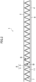
FIG. 2 is an enlarged front view of the ambulatory pest trapping device according to the first embodiment of the present invention. -
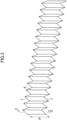
FIG. 3 is a perspective view for explaining an adhesive sheet in the ambulatory pest trapping device according to the first embodiment of the present invention. -
FIG. 4 is a C-C sectional view ofFIG. 3 , which is a partially enlarged view for explaining a pointed protrusion in the ambulatory pest trapping device according to the first embodiment of the present invention. -
FIG. 5 is a diagram for explaining the definition of the pointed protrusion. -
FIG. 6 is a diagram for explaining the total length of the pointed protrusion per unit area in the ambulatory pest trapping device according to the first embodiment of the present invention. -
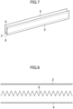
FIG. 7 is a diagram for explaining a method for producing the ambulatory pest trapping device according to the first embodiment of the present invention. -
FIG. 8 is another diagram for explaining the method for producing the ambulatory pest trapping device according to the first embodiment of the present invention. -
FIG. 9 is a perspective view of an ambulatory pest trapping device according to a second embodiment of the present invention. -
FIG. 10 is a view as seen from an arrow A ofFIG. 9 . -
FIG. 11 is a view as seen from an arrow B ofFIG. 9 . -
FIG. 12 is a D-D sectional view ofFIG. 9 , which is a partially enlarged view for explaining a pointed protrusion in the ambulatory pest trapping device according to the second embodiment of the present invention. -
FIG. 13 is a diagram for explaining a method for producing the ambulatory pest trapping device according to the second embodiment of the present invention. -
FIG. 14 is a diagram for explaining a method for producing the ambulatory pest trapping device according to the second embodiment of the present invention. -
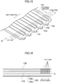
FIG. 15 is another diagram for explaining the method for producing the ambulatory pest trapping device according to the second embodiment of the present invention. -
FIG. 16 is a view as seen from an arrow Q ofFIG. 15 . -
FIG. 17 is a perspective view for explaining the pointed protrusion in the ambulatory pest trapping device according to the second embodiment of the present invention. -
FIG. 18 is a view as seen from an arrow K ofFIG. 17 . -
FIG. 19 is a view as seen from an arrow G ofFIG. 17 . -
FIG. 20 is a perspective view of a variation of the ambulatory pest trapping devices according to the embodiments of the present invention. -
FIG. 21 is a perspective view of another variation of the ambulatory pest trapping devices according to the embodiments of the present invention. -
FIG. 22 is a partially enlarged view for explaining a pointed protrusion of the ambulatory pest trapping device ofFIG. 21 . -
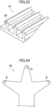
FIG. 23 is a perspective view of another variation of the ambulatory pest trapping devices according to the embodiments of the present invention. -
FIG. 24 is a partially enlarged view for explaining a pointed protrusion of the ambulatory pest trapping device ofFIG. 23 . -
FIG. 25 is a perspective view of another variation of the ambulatory pest trapping devices according to the embodiments of the present invention. -
FIG. 26 is a sectional view for explaining a pointed protrusion in the ambulatory pest trapping device ofFIG. 25 . -
FIG. 27 is another sectional view for explaining the pointed protrusion in the ambulatory pest trapping device ofFIG. 25 . -
FIG. 28 is a diagram for explaining the number of apexes of cone-shaped pointed protrusion per unit area in the ambulatory pest trapping device ofFIG. 25 . -
FIG. 29 is a perspective view of another variation of the ambulatory pest trapping devices according to the embodiments of the present invention. -
FIG. 30 is a perspective view for explaining a square box used in Examples. -
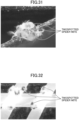
FIG. 31 is a photograph showing the state where a pointed protrusion of an ambulatory pest trapping device of Example 1 traps twospotted spider mites. -
FIG. 32 is a photograph showing the state where pointed protrusions of an ambulatory pest trapping device of Example 2 trap twospotted spider mites. -
FIG. 33 is a perspective view of an ambulatory pest trapping device according to a third embodiment of the present invention. -
FIG. 34 is a plan view of the ambulatory pest trapping device according to the third embodiment of the present invention. -
FIG. 35 is a partially enlarged view for explaining a pointed protrusion of the ambulatory pest trapping device ofFIG. 33 . -
FIG. 36 is a partially enlarged view for explaining a pointed protrusion of the ambulatory pest trapping device ofFIG. 34 . -
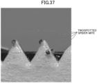
FIG. 37 is a photograph showing the state where pointed protrusions of an ambulatory pest trapping device of Example 3 trap twospotted spider mites. - Embodiments of the present invention will be described in detail below, with reference to the drawings. The present invention is not limited to the embodiments below.
- Ambulatory pests in the present invention refer to pests that move by crawling or creeping among pests such as agricultural pests which eat crop plants such as grains, vegetables, and fruits cultivated in rice fields, fields, and the like and suck juices thereof to cause damage, sanitary pests that cause harm to human and animals by biting or stinging their bodies, and unpleasant pests that cause discomfort although they have little direct influence on the human bodies. Ambulatory pests also include pests which are flying pests but are capable of moving by crawling.
- Examples of the agricultural pests include: whiteflies, stink bugs, greenflies, scale insects, pests of the order Thysanoptera, pests of the order Acarina such as families Tetranychidae, Eriophyidae, Tarsonemidae, Acaridae, and the like which are plant parasitic, larvae of butterflies and moths, and slugs. Examples of the sanitary pests and the unpleasant pests include bedbugs, ants, cockroaches, mites, centipedes, millipedes, and spiders.
-
FIG. 1 is a perspective view of an ambulatory pest trapping device according to the first embodiment of the present invention.FIG. 2 is an enlarged front view of the ambulatory pest trapping device according to the first embodiment of the present invention.FIG. 3 is a perspective view for explaining an adhesive sheet in the ambulatory pest trapping device according to the first embodiment of the present invention.Fig. 4 is a C-C sectional view ofFIG. 3 , which is a partially enlarged view for explaining a pointed protrusion in the ambulatory pest trapping device according to the first embodiment of the present invention. - An ambulatory
pest trapping device 1 according to the present embodiment includes anupper sheet 2 on which ambulatory pests B are capable of crawling, alower sheet 4 which is provided to face theupper sheet 2 and on which the ambulatory pests B are capable of crawling, and a corrugatedintermediate sheet 3 provided between theupper sheet 2 and thelower sheet 4. -
Spaces 11 through which the ambulatory pests B can pass are formed between theupper sheet 2 and theintermediate sheet 3 and between thelower sheet 4 and theintermediate sheet 3. - As illustrated in
FIGS. 1 to 4 , in the ambulatorypest trapping device 1 according to the present embodiment, anadhesive sheet 8 in which theintermediate sheet 3 is covered with an adhesive 5 is provided, and ridged pointedprotrusions 7 made of the adhesive 5 covering ends 6 of theintermediate sheet 3 is provided in the width direction P of theadhesive sheet 8. - The
ambulatory pests 8 which have crawled on theupper sheet 2, thelower sheet 4, and theadhesive sheet 8 in which theintermediate sheet 3 is covered with the adhesive 5 reach the pointedprotrusions 7 made of the adhesive 5. While the ambulatory pests B are crawling on the pointedprotrusions 7, the abdomens thereof are adhered to the adhesive 5 forming the pointedprotrusions 7, and the legs thereof are float in the air, so that the ambulatory pests B cannot move and are trapped. - As described above, in the ambulatory
pest trapping device 1 according to the present embodiment, the ambulatory pests B can be trapped on the entirepointed protrusions 7 illustrated inFIGS. 1 to 3 , i.e., the ambulatorypest trapping device 1 has a structure capable of efficiently trapping the ambulatory pests B and particularly can efficiently trap pests of the order Acarina such as families Tetranychidae, Eriophyidae, Tarsonemidae, Acaridae, and the like which are plant parasitic. - It is known that the order Acarina, particularly spider mites, has strong leg power and moves around in a wide range. Since the tips of the legs are pointed so as to easily climb the surface of the plant, the legs are not caught on the flat adhesive surface and can relatively freely move around. Therefore, it is difficult to trap the legs of spider mites by adhesion with a flat adhesive sheet.
- In contrast, the ambulatory
pest trapping device 1 according to the present embodiment is based on the findings obtained by observation of the behavior of spider mites, and when ambulatory pests such as spider mites move on the pointedprotrusions 7 made of the adhesive 5, the tips of the pointed protrusions come into contact with the abdomens thereof, so that the ambulatory pests such as spider mites can be efficiently trapped. - The "pointed protrusion" refers to, as illustrated in
FIG. 5 , a portion defined by the tip radius of curvature R (i.e., the circular portion of the tip surrounded by solid and dashed lines inFIG. 5 ) in a cross section of an object having a protrusion (corresponding to the cross section illustrated inFIG. 5 , provided that the cross section of the object is parallel with the direction Y in which the protrusion is projecting and includes a top portion F of the protrusion, and when the protrusion is ridged, the cross section of the object is a cross section in the direction orthogonal to the length direction of the ridge (i.e., C-C cross section inFIG. 3 )). - Further, the "tip radius of curvature R" refers to, as illustrated in
FIG. 5 , a radius of a circle closest to the shape of the pointed protrusion in the sectional view of the pointed protrusion. - In the present embodiment, the tip radius of curvature of the
pointed protrusion 7 is 0.001 mm to 1.0 mm. If the tip radius of curvature is less then the lower limit, it is difficult to actually produce the pointed protrusion by injection molding, and the pointed protrusion becomes fragile and easily deformed, which is not preferable. If the tip radius of curvature is larger than the upper limit, the pointed protrusion becomes relatively gentle, and even if ambulatory pests move on the protrusion, it is difficult to catch them by adhering their abdomens, which is not preferable. The range of the tip radius of curvature R is preferably 0.005 mm to 0.5 mm, more preferably 0.01 mm to 0.2 mm. - With such a configuration, the ambulatory pests B crawling on the pointed
protrusions 7 are easily caught by the pointedprotrusions 7, and the abdomens thereof are easily adhered to the pointedprotrusions 7, thereby improving the efficiency of trapping the ambulatory pests B. - For each of the pointed
protrusions 7 of the present embodiment, as illustrated inFIG. 4 , half of the thickness T of the adhesive (double-sided adhesive sheet) 5 forming the pointed protrusion 7 (i.e., T/2) is the tip radius of curvature R. - Further, in the present embodiment, the sum L of lengths of the ridged pointed
protrusions 7 per unit area (1 cm2) is preferably from 10 mm/cm2 to 1000 mm/m2 inclusive. When the sum L is larger than the lower limit, the trapping efficiency is not reduced, thereby providing excellent practicality. When the total length L is the upper limit or less, the distance between the ridges is not too small, and each ridge can independently exhibit the trapping efficiency. - Note that the "ridged" refers to the state where the pointed
protrusions 7 are connected in a ridge line shape and have a specific length. - For example, in the ambulatory
pest trapping device 1 illustrated inFIG. 6 , the length of the ambulatorypest trapping device 1 is represented by N, and the height of the ambulatory pest trapping device 1 (i.e., the separation distance between theend 2a of theupper sheet 2 and theend 4a of the lower sheet 4) is represented by H. For example, if the length N is 10 cm, the height is 1 cm, and the total length of the pointed protrusion 7 (i.e., the length fromend point 7a to end point 7b) is 360 mm, the sum L of lengths of the ridged pointedprotrusions 7 per unit area (1 cm2) is 360 [mm]/(10 [cm] × 1 [cm]) = 36 mm/cm2. - With such a configuration, the number of pointed
protrusions 7 per unit area increases. Thus, the ambulatory pests B crawling on the pointedprotrusions 7 are easily caught by the pointedprotrusions 7, and the abdomens thereof are easily adhered to the adhesive 5 forming the pointedprotrusions 7, thereby improving the efficiency of trapping the ambulatory pests B. - The configuration continuously having a larger number of such structures allows more pointed protrusions to be secured. Further, in view of improving productivity, the ambulatory
pest trapping device 1 may be configured by forming a sheet continuously having such structures in a roll shape and processing the sheet to have a predetermined width and a predetermined length. - Each size (the length N, the heigh H, the width W) of the ambulatory
pest trapping device 1 is not particularly limited, and can be set appropriately according to the intended use. For example, when the ambulatorypest trapping device 1 is used to eliminate spider mites at a protected horticulture site, the length N thereof may be 30 cm to 100 cm, the height H thereof may be 1 cm to 5 cm, and the width thereof may be 1 cm to 5 cm, considering the size of spider mites (0.5 mm to 1 mm). - For example, when the ambulatory
pest trapping device 1 is used to eliminate house dust mites at home or in a facility, the length N thereof may be 5 cm to 20 cm, the height H thereof may be 1 cm to 5 cm, and the width W thereof may be 1 cm to 5 cm, considering the size of the house dust mites (0.2 mm to 0.5 mm). In such a case, the ambulatorypest trapping device 1 may be placed in a gap between futons and under cushions and carpets where house dust mites are likely to be hiding. - The
upper sheet 2 and thelower sheet 4 evenly hold theintermediate sheet 3 covered with the adhesive 5 to impart strength to theintermediate sheet 3 such that theintermediate sheet 3 can be handled as a sheet while providing floor surfaces on which the ambulatory pests B are capable of crawling. - The
upper sheet 2 and thelower sheet 4 suitably have moderate irregularities that facilitate crawling of the ambulatory pests B, rather than having a smooth surface, and preferably have, for example, a roughness equal to or rougher than P600 according to ISO 6344-3. - Examples of the material for forming the
upper sheet 2 and thelower sheet 4 include films made of cellulose-based paper and thermoplastic resins such as polyester resin, polyamide resin, polyvinyl chloride resin, polyolefin resin, and acrylic resin. - The
upper sheet 2 and thelower sheet 4 used are flexible and thin, have good adhering properties with the adhesive 5, have endurance to the adhesive 5, and have good dimensional stability. Theupper sheet 2 and thelower sheet 4 may have light-shielding properties or light transparency. When the ambulatorypest trapping device 1 is placed outdoors, theupper sheet 2 and thelower sheet 4 used are preferably water resistant or weather resistant. - Examples of the sheet having light-shielding properties may include a sheet of paper, polylaminated paper, and a film which are colored in black or any other medium-dark color.
- As a light-transparent sheet, a transparent film including thermoplastic resin such as polyester resin, polyamide resin, polyvinyl chloride resin, polyolefin resin, or acrylic resin may be used.
- When the ambulatory pests are house dust mites having a habit of preferring dark places, the
upper sheet 2 having light-shielding properties makes it possible to trap more efficiently the ambulatory pests by using the habit. On the other hand, when theupper sheet 2 and thelower sheet 4 have light transparency, trapped ambulatory pests may be easily visible from the outside of the device. - The
intermediate sheet 3 is sandwiched between theupper sheet 2 and thelower sheet 4 to hold the pointedprotrusions 7 made of the adhesive 5. - Examples of the material for forming the
intermediate sheet 3 include films made of cellulose-based paper and thermoplastic resins such as polyester resin, polyamide resin, polyvinyl chloride resin, polyolefin resin, acrylic resin, as for theupper sheet 2 and thelower sheet 4 described above. - The
upper sheet 2 and thelower sheet 4 used are flexible and thin, have good adhering properties with the adhesive 5, have endurance to the adhesive 5, and have good dimensional stability. When the ambulatorypest trapping device 1 is placed outdoors, theupper sheet 2 and thelower sheet 4 used are preferably water resistant or weather resistant. - The adhesive 5 is configured to come into contact with ambulatory pests B and traps the ambulatory pests B by its adhesive surface. The adhesive 5 is not particularly limited as long as having appropriate adhesiveness for trapping the ambulatory pests B. The adhesive 5 may be made of an acrylic, rubber-based, SIS block-based, silicon-based, or urethan-based adhesive. Note that these adhesives may be used alone or in combination of two or more of them.
- As the adhesive 5, a double-sided adhesive sheet may also be used. In such a case, the double-sided adhesive sheet includes a sheet-like substrate and adhesives applied on both sides of the substrate, and the substrate sandwiched between the adhesives is not particularly limited, and a thin sheet-like substrate such as paper and a film can be used.
- In view of reliably trapping the ambulatory pests B, the
adhesive sheet 5 is preferably a permanently bonding adhesive sheet that bonds a target to be adhered semi-permanently once the adhesive sheet is adhered to the target. A removable adhesive sheet that is to be peeled off after sticking for a certain period of time has relatively worse adhesiveness and may thus be not preferably used. - The ambulatory
pest trapping device 1 of the present embodiment may contain a phosphorescent substance. The phosphorescent substance attracts ambulatory pests and easily guides them into the pointedprotrusions 7. - More specifically, for example, it is known that nondormant female spider mites which act from spring to autumn have a property of avoiding ultraviolet light and preferring visible light, and spider mites are attracted to visible light emitted by the phosphorescent substance in the ambulatory
pest trapping device 1 of the present embodiment at night, and therefore, the trapping efficiency can be further improved. - The phosphorescent substance is not particularly limited as long as having an effect of attracting target ambulatory pests to be trapped, and examples thereof include a yellow-green luminescent phosphorescent pigment (SrAl2O4:Eu, Dy), which is strontium aluminate activated with europium and dysprosium and blue-green luminescent phosphorescent pigment (Sr4Al14O25:Eu, Dy).
- The
upper sheet 2, thelower sheet 4, theintermediate sheet 3, and the adhesive 5 may contain these phosphorescent substances. When theupper sheet 2, thelower sheet 4, and theintermediate sheet 3 are made of resin, the phosphorescent substance may be kneaded into the resin. In such a case, the phosphorescent substance is gradually released from the inside of the resin molded body, advantageously resulting in a longer lasting effect compared with surface-coated attractants. - As illustrated in
FIGS. 1 to 2 , the ambulatorypest trapping device 1 according to this embodiment includes an attachingadhesive sheet 9 on a surface of thelower sheet 4 opposite to theadhesive sheet 8. Therefore, when the ambulatorypest trapping device 1 is attached to a wall, it may be easily attached to the wall surface to be adhered. The attachingadhesive sheet 9 may be provided on the surface of theupper sheet 2 opposite to theadhesive sheet 8. - The attaching
adhesive sheet 9 may also be used to stack the ambulatorypest trapping device 1 on another ambulatorypest trapping device 1 and integrate them. - In addition, the attaching
adhesive sheet 9 may be made of an acrylic adhesive which is easily removable. Note that these adhesives may be used alone or in combination of two or more of them. - The method of using the ambulatory
pest trapping device 1 is not particularly limited, and the ambulatorypest trapping device 1 in a cylindrical shape may be placed to surround the periphery of nursery plant, for example. More specific examples of such a method include placing the ambulatorypest trapping device 1 to surround the trunk of tree, placing the ambulatorypest trapping device 1 like a fence around plant such as vegetable seedling, and placing the ambulatorypest trapping device 1 side by side at the root of plant. - Next, an example of a method for producing the ambulatory
pest trapping device 1 of this embodiment will be described. - As illustrated in
FIG. 7 , two double-sided adhesive sheets 5 which are adhesives are arranged to face each other, and anintermediate sheet 3 intervenes therebetween - Then, from the state illustrated in
FIG. 7 , the two double-sided adhesive sheets 5 are attached to each other to completely cover theintermediate sheet 3 and adhered to each other so that portions of the double-sided adhesive sheets 5 covering theends 6 of theintermediate sheet 3 are superimposed on each other. Thus, as illustrated inFIG. 4 , anadhesive sheet 8 having ridged pointedprotrusions 7 made of the double-sided adhesive sheets 5 covering theends 6 of theintermediate sheet 3 is formed. - Then, the
adhesive sheet 8 is folded at predetermined intervals in the longitudinal direction to form a corrugatedadhesive sheet 8 illustrated inFIG. 3 . - Then, as illustrated in
FIG. 8 , anupper sheet 2 and alower sheet 4 are arranged to face each other, and theadhesive sheet 8 illustrated inFIG. 3 is interposed between theupper sheet 2 and thelower sheet 4. - Subsequently, from the state illustrated in
FIG. 8 , theupper sheet 2 and thelower sheet 4 are pressed toward the corrugatedadhesive sheet 8 to bring theadhesive sheet 8 into contact with theupper sheet 2 and thelower sheet 4. Thus, an ambulatorypest trapping device 1 including pointedprotrusions 7 can be formed as illustrated inFIGS. 1 to 2 and4 . - Next, the second embodiment of the present invention will be described. The same components as those of the first embodiment are denoted by the same reference numerals, and the description thereof will be omitted.
-
FIG. 9 is a perspective view of an ambulatory pest trapping device according to a second embodiment of the present invention.FIG. 10 is a view as seen from an arrow A ofFIG. 9 .FIG. 11 is a view as seen from an arrow B ofFIG. 9 .FIG. 12 is a D-D sectional view ofFIG. 9 , which is a partially enlarged view for explaining a pointed protrusion in the ambulatory pest trapping device according to the second embodiment of the present invention. - As illustrated in
FIGS. 9 to 12 , the ambulatorypest trapping device 15 of the present embodiment is configured such that an adhesive is provided on the surface of a mesh-like molded surface fastener made of thermoplastic resin. - The ambulatory
pest trapping device 15 includesfirst strands 10,second strands 20, engagement elements (hooks) 30, and pores 40 and is configured such that the adhesive 5 is provided on the surface of a mesh-like molded surface fastener made of a sheet-like molded body 100 (seeFIG. 14 ) made of thermoplastic resin and by an extruder. - As illustrated in
FIGS. 9 to 12 , for the ambulatorypest trapping device 15 of the present embodiment, pointedprotrusions 30a in each of which aflange portion 31 in the mesh-like molded surface fastener made of thermoplastic resin is covered with the adhesive 5 are provided. - In production of the ambulatory
pest trapping device 15 of the present embodiment, first, a mesh-like molded surface fastener is made of thermoplastic resin by using amolding die 1000 of an extruder illustrated inFIG. 13 . - The molding die 1000 has an
opening 1100 as illustrated inFIG. 13 , and in cross section thereof, theopening 1100 has anintermediate space 1110 having a predetermined width in a width direction (direction orthogonal to the extruding direction) and a height of several millimeters or less at a middle position in the vertical direction, a plurality of lower protrudingspaces 1120 protruding downward of theintermediate space 1110 and formed at predetermined intervals in the width direction of theintermediate space 1110, and upper protrudingspaces 1130 protruding upward opposite to the lower protrudingspaces 1120. - Then, a molding material is fed into the molding die 1000 and extruded, so that as illustrated in
FIG. 14 , aflat base layer 110 is extruded from theintermediate space 1110, andlower ribs 120, which are one ribs, andupper ribs 130, which are the other rib, are extruded from the lower protrudingspaces 1120 and the upper protrudingspaces 1130, respectively. - Thus, a
base layer 110 is formed as a sheet-like moldedbody 100 in which thelower ribs 120 as one ribs extending in the extruding direction on one surface and theupper ribs 130 as the other ribs extending in the extruding direction on the other surface are integral with each other. - The
upper ribs 130form engagement elements 30 each having a pointedprotrusion 30a (seeFIGS. 10 and12 ) protruding outward in the width direction in the ambulatorypest trapping device 15. Thus, the sectional shape of theupper rib 130, i.e., the sectional shape of theupper protruding space 1130 of the molding die has: aportion 1130b corresponding to thestem 30b which matches the sectional shape of theengagement element 30 illustrated inFIGS. 10 and12 and extends upward from theintermediate space 1110; and aportion 1130a protruding outward at its upper end (seeFIG. 13 ). - In the present embodiment, as illustrated in
FIG. 10 , thesecond strand 20 includes astem 20b protruding downward from the first strand 10 (base layer 110) and a parasol-like portion 20a protruding outward on both sides of thestem 20b in the width direction in a lower end portion of thestem 20b. Thus, thelower protruding space 1120 has a relativelynarrow portion 1120b extending downward from theintermediate space 1110 and awide portion 1120a protruding outward on both sides in the width direction in the lower end portion. - Therefore, in the
lower rib 120 as one rib extruded from thelower protruding space 1120, apotion 120b extruded from the relativelynarrow portion 1120b constitutes thestem 20b of thesecond strand 20, and aportion 120a extruded from thewide portion 1120a constitutes the parasol-like portion 20a of thesecond strand 20. - In the extruded sheet-like molded
body 100, as illustrated inFIGS. 15 and 16 , cuts are made from the tops of theupper ribs 130 to the boundary (the position indicated by reference sign S inFIG. 16 ) with thelower ribs 120 in thebase layer 110 at predetermined intervals in the extruding direction as illustrated inFIG. 15 along the width direction orthogonal to the extruding direction or along the direction inclined at a predetermined angle with respect to the width direction. - Then, the sheet-like molded
body 100 is stretched in the extruding direction illustrated inFIG. 15 . Accordingly, as illustrated inFIGS. 15 to 16 , thelower rib 120 extends in the stretching direction, while theupper ribs 130 and thebase layer 110 are cut at predetermined intervals, so that portions between the cuts are separated from each other. - As a result, spaces are formed between the portions between the cuts, which serve as pores 40. The stretching continues until the
pores 40 each have a predetermined size, and in this state, the sheet-like moldedbody 100 is cooled to fix that shape. - In such processes, the mesh-like molded surface fastener, which serves as a base of the ambulatory
pest trapping device 15 of the present embodiment, is produced. Portions separated at the cuts of thebase layer 110 serve as resin portions forming a plurality offirst strands 10 provided in substantially parallel with each other at intervals as illustrated inFIGs. 9 to 11 , and thelower ribs 120 serve as resin portions forming a plurality ofsecond strands 20 provided in substantially parallel with each other at intervals along the direction intersecting the longitudinal direction of thefirst strand 10. Further, portions separated at the cuts of theupper ribs 130 serve resin portions forming separatedengagement elements 30. - Then, the mesh-like molded surface fastener is cut in predetermined dimensions according to the desired application, and an adhesive 5 is provided for the surface of the mesh-like molded surface fastener. Thus, an ambulatory
pest trapping device 15 including pointedprotrusions 30a in each of which aflange portion 31 in the molded surface fastener is covered with the adhesive 5 is produced as illustrated inFIGS. 9 to 12 . - In the ambulatory
pest trapping device 15 in which the adhesive 5 is provided for the surface of the mesh-like molded surface fastener which serves as a base, as illustrated inFIG. 9 , theengagement elements 30 are provided to protrude on the opposite side of thesecond strands 20 across the first strands 10 (base layer 110). - Further, since a plurality of
first strands 10 are arranged at intervals from each other, and a plurality ofsecond strands 20 are arranged at intervals from each other so as to intersect thefirst strands 10, apore 40 is formed at a position surrounded by adjacentfirst strands 10 and adjacentsecond strands 20. - Then, ambulatory pests B crawling on the ambulatory
pest trapping device 15 reach hook-likepointed protrusions 30a covered with the adhesive 5, and while crawling on the pointedprotrusions 30a, the abdomens thereof are adhered to the adhesive 5 forming the pointedprotrusions 30a, and the legs thereof are float in the air, so that the ambulatory pests B cannot move and are trapped. As described above, in the ambulatorypest trapping device 15 according to the present embodiment, the ambulatory pests B can be trapped on the entirepointed protrusions 30a illustrated inFIGS. 9 to 12 , i.e., the ambulatorypest trapping device 15 has a structure capable of efficiently trapping the ambulatory pests B. - In the present embodiment, the tip radius of curvature R of each pointed
protrusion 30a is 0.001 mm to 1.0 mm. With such a configuration, the ambulatory pests B crawling on the pointedprotrusions 30a are easily caught by the pointedprotrusions 30a, and the abdomens thereof are easily adhered to the pointedprotrusions 30a, thereby improving the efficiency of trapping the ambulatory pests B. - For the side portion (the view taken along the line K of
FIG. 17 ) of thepointed protrusion 30a in the present embodiment, as illustrated inFIG. 18 , for example, when the height h of thepointed protrusion 30a (seeFIG. 12 ) is 0.2 mm, half of the height h (i.e., h/2) is the tip radius of curvature R (i.e., R = 0.1 mm). - Further, as illustrated in
FIG. 19 , in the upper side portion of thepointed protrusion 30a (the view taken along the like G ofFIG. 17 ), the tip radius of curvature R can be 0.01 mm, for example. - Each size of the ambulatory
pest trapping device 15 is not particularly limited, and can be set appropriately set according to the intended use. For example, the pitch between thefirst strands 10 may be 2 mm to 4mm, the width of thesecond strand 20 may be 0.2 mm to 1.0 mm, and the width of theengagement element 30 may be 0.5 mm to 3 mm. - The method of using the ambulatory
pest trapping device 15 is not particularly limited, and the ambulatorypest trapping device 15 in a ring shape may be placed around the crop plant or attached around a trunk of a fruit tree. - Since the molded surface fastener made of thermoplastic resin is produced as described above, the
first strands 10, thesecond strands 20, and theengagement elements 30 are integral with each other. Since the thermoplastic resin is used as a material, thefirst strands 10, thesecond strands 20, and theengagement elements 30 have predetermined strengths. - Examples of the thermoplastic resin forming the mesh-like molded surface fastener include nylon-based resin such as
nylon 6 and nylon 66, polyester-based resin such as polylactic acid and polyethylene terephthalate and polybutylene terephthalate, and an ethylene-vinyl alcohol copolymer. In view of durability, heat resistance, molding processability, and the like, a thermoplastic polyester elastomer is preferably used. In view of ecology in disposal after use, bioplastics such as polyethylene terephthalate, polyethylene, polypropylene, polyamide, polytetraethylene terephthalate from biomass and biodegradable polylactic acid, polyhydroxyalkanoic acid, polybutylene succinate, polyethylene succinate, polyethylene succinate adipate, polybutylene adipate terephthalate, polycaprolactone, and the like can also be used. - Next, the third embodiment of the present invention will be described. The same components as those of the first embodiment are denoted by the same reference numerals, and the description thereof will be omitted.
- The ambulatory pest trapping device of the present embodiment is characterized in that instead of the mesh-like molded surface fastener in the second embodiment above, paper or a mesh-like resin structure made of resin is used, and the paper or mesh-like resin structure with the adhesive described above on its surface is punched out, so that pointed protrusions covered with the adhesive are formed at least in part of the ambulatory pest trapping device.
-
FIGS. 33 and34 are schematic views of an ambulatory pest trapping device according to the third embodiment of the present invention.FIG. 35 is a partially enlarged view for explaining a pointed protrusion in the ambulatory pest trapping device illustrated inFIG. 33 , andFIG. 36 is a partially enlarged view for explaining a pointed protrusion of the ambulatory pest trapping device illustrated inFIG. 34 . - As the
paper 41 serving as the base of the ambulatorypest trapping device 25 illustrated inFIG. 33 , for example, a commercially available cardboard or the like can be used, and the ambulatorypest trapping device 25 is formed by punching out the paper having the adhesive 5 provided on the surface thereof. As illustrated inFIG. 33 , for the ambulatorypest trapping device 25, pointedprotrusions 45 formed by the punching out of thepaper 41 serving as a base covered with the adhesive 5 are provided. - The mesh-like resin structure serving as a base of the ambulatory
pest trapping device 26 illustrated inFIG. 34 can be produced by an extruder for producing a net made of low-density polyethylene, for example, and the ambulatorypest trapping device 26 is formed by punching out the mesh-like resin structure with the adhesive 5 provided on the surface thereof. As illustrated inFIG. 34 , for the ambulatorypest trapping device 26, pointedprotrusions 46 formed by the punching out ofresin 42 for forming the mesh-like resin structure serving as a base covered with the adhesive 5 are provided. - As described above, in the present embodiment, the number of the pointed
protrusions FIGS. 33 and34 by performing the punching process described above, and the increase causes the efficiency of trapping the crawling ambulatory pests B to be improved. - Ambulatory pests B crawling on the ambulatory
pest trapping device protrusions protrusions protrusions pest trapping device 25 according to the present embodiment, the ambulatory pests B can be trapped on the entirepointed protrusions FIGS. 33 and34 , i.e., the ambulatorypest trapping device - In the ambulatory
pest trapping device 25, the tip radius of curvature R of the pointedprotrusion 45 illustrated inFIG. 35 is 0.001 mm to 1.0 mm (e.g., 0.15 mm). Similarly, in the ambulatorypest trapping device 26, the tip radius of curvature R of the pointedprotrusion 46 illustrated inFIG. 36 is 0.001 mm to 1.0 mm (e.g., 0.05 mm to 0.5 mm). With such a configuration, the ambulatory pests B crawling on the pointedprotrusions protrusions protrusions - Further, as in the first embodiment, the sum L of the lengths of the pointed protrusions 45 (or the pointed protrusions 46) per unit area (1 cm2) is preferably from 10 mm/cm2 to 1000 mm/m2 inclusive.
- As in the ambulatory
pest trapping device 19 illustrated inFIG. 28 , the number P of apexes of the pointed protrusions 45 (or the pointed protrusions 46) per unit area (1 cm2) is preferably from 10/cm2 to 1000/cm2 inclusive. - The pitch between the pointed protrusions 45 (or the pointed protrusions 46) is preferably such that the ambulatory pests B cannot easily move from one pointed
protrusion 45 to the other pointed protrusion 45 (or one pointedprotrusion 46 to the other pointed protrusion 46) - The embodiments may be modified as described below.
- For example, in the second embodiment, the hook-like
pointed protrusions 30a are provided. However, the shape of each pointedprotrusion 30a is not particularly limited, and may be, for example, a cylindrical shape or a polygonal prism shape (such as a triangular prism shape, a quadrangular prism shape, or a hexagonal prism shape). - In the second embodiment, pointed
protrusions 30a are provided for one surface (thefirst strand 10 side) of the ambulatorypest trapping device 15. However, pointedprotrusions 30a may be provided for both surfaces (thefirst strand 10 side and thesecond strand 20 side). - In the second embodiment, the sheet-like molded
body 100 is stretched to separate the portions with the cuts interposed therebetween, and thus theengagement elements 30 including the pointedprotrusions 30a are provided to be separated from each other. However, as in the ambulatorypest trapping device 16 illustrated inFIG. 20 , the sheet-like moldedbody 100 may not be stretched, the engagement elements 30 (i.e., the pointedprotrusions 30a) may be continuous without separation, and ridged pointedprotrusions 36 formed by the continuouspointed protrusions 30a may be provided. - The shape of the ridged pointed
protrusion 36 illustrated inFIG. 20 is not particularly limited, and for example, as in the ambulatorypest trapping device 17 illustrated inFIGS. 21 and 22 , ridged pointedprotrusions 37 each having a substantially triangular prism shape may be provided. In such a case, the tip radius of curvature R may be set to 0.05 mm. - Similarly, for example, as in the ambulatory
pest trapping device 18 illustrated inFIGs. 23 and 24 , ridged pointedprotrusions 38 having a substantially polygonal prism shape may be provided.. In such a case, the tip radius of curvature R may be set to 0.05 mm. - In the embodiments, ridged pointed protrusions are provided. However, cone-shaped pointed protrusions may be provided instead of the ridged pointed protrusions. More specifically, as in the ambulatory
pest trapping device 19 illustrated inFIG. 25 , a plurality of pointedprotrusions 39 each having a substantially conical shape may be provided. - The pointed
protrusion 39 includes, as illustrated inFIG. 26 , aflange portion 22 integral with abase 21 and an adhesive 5 covering theflange portion 22. Thebase 21 and theflange portion 22 may be produced by injection molding, extrusion molding, and blow molding, or the like using polyethylene, for example. Also in such a case, the tip radius of curvature R illustrated inFIG. 27 may be set to 0.05 mm. - Then, ambulatory pests B crawling on the ambulatory
pest trapping device 19 reach conicalpointed protrusions 39 covered with the adhesive 5, and while crawling on the pointedprotrusions 39, the abdomens thereof are adhered to the adhesive 5 forming the pointedprotrusions 39, and the legs thereof are float in the air, so that the ambulatory pests B cannot move and are trapped. As described above, in the ambulatorypest trapping device 19, the ambulatory pests B can be trapped on the entirepointed protrusions 39 illustrated inFIG. 25 , i.e., the ambulatorypest trapping device 19 has a structure capable of efficiently trapping the ambulatory pests B. - As in the ambulatory
pest trapping device 19, the number P ofapexes 39a of the cone-shaped pointedprotrusions 39 per unit area (1 cm2) is preferably from 10/cm2 to 1000/cm2 inclusive. When the number P is equal to or larger than the lower limit, the trapping efficiency is not reduced, thereby providing excellent practicality. When the number P is equal to or lower than the upper limit, the pointed protrusions can be formed with high producing accuracy. - In the ambulatory
pest trapping device 19 illustrated inFIG. 28 , the number ofapexes 39a of the pointedprotrusions 39 is 25/cm2. - With such a configuration, the number of pointed
protrusions 39 per unit area increases. Thus, the ambulatory pests B crawling on the pointedprotrusions 39 are easily caught by the pointedprotrusions 39, and the abdomens thereof are easily adhered to the adhesive 5 forming the pointedprotrusions 39, thereby improving the efficiency of trapping the ambulatory pests B. - The shape of the pointed
protrusion 39 illustrated inFIGS. 25 to 28 is not limited to a conical shape, and may be, for example, a polygonal pyramid shape (for example, a triangular pyramid shape or a quadrangular pyramid shape). - The ambulatory pest trapping device may have combination of ridged pointed protrusions and cone-shaped pointed protrusions. For example, as in the ambulatory
pest trapping device 23 illustrated inFIG. 29 , combination of ridged pointedprotrusions 37 each having a triangular prism shape illustrated inFIG. 21 and a plurality of pointedprotrusions 39 each having a conical shape illustrated inFIG. 25 may be used. - The ambulatory pest trapping device may have at least one of ridged pointed protrusions or cone-shaped pointed protrusions.
- As illustrated in
FIG. 30 , a square box 50 (length: 5 cm, width: 5 cm, height: 5 cm) made of commercially available black cardboard (thickness: 0.21 mm) was prepared, and the produced ambulatory pest trapping device was attached to thesurface 51a on theupper side 52, which is parts of the fourouter surfaces 51 of thebox 50. - Next, 100 twospotted spider mites (non-dormant females) were placed inside the
box 50, and after 24 hours, the number of twospotted spider mites trapped on pointed protrusions of the ambulatory pest trapping device was counted, and the trapping rate was calculated using the following equation (1). The process was performed a total of three times, and the average value of the trapping rates was determined.
[Math. 1]
- Commercially available Kent paper (thickness: 0.21 mm) serving as an intermediate sheet was cut into a size of 10 mm wide and 364 mm long, and commercially available double-sided tapes (manufactured by KIKUSUI TAPE, trade name:
KIKUDOUBLE 200, width: 20 mm, thickness: 0.084 mm) as adhesives were attached to both sides of the cut sheet. At this time, the double-sided tapes were attached to cover the entire 10 mm width Kent paper and were adhered to each other so that ridged pointed protrusions made of the double-sided tapes were formed on both ends of the Kent paper in the width direction. Then, the Kent paper to which double-sided tapes had been adhered was creased at intervals of 10 mm in the length direction to produce a bellows-shaped body (i.e., an adhesive sheet in which an intermediate sheet is covered with the adhesives) with a width of 20 mm, a height of 10 mm, and a length of 100 mm. - Further, two sheets each with a width of 10 mm and a length of 100 mm were cut out from commercially available Kent paper (thickness: 0.21 mm) and used as an upper sheet and a lower sheet. Then, the upper sheet and the lower sheet were disposed to face each other, and the adhesive sheet which is the bellows-shaped body intervened therebetween.
- Subsequently, from the state, the upper sheet and the lower sheet were pressed toward the adhesive sheet to bring the adhesive sheet into contact with the upper sheet and the lower sheet. Thus, an ambulatory pest trapping device including pointed protrusions was produced.
- In such a case, ridged pointed protrusions made of an adhesive (adhesive tape) covering the ends of the intermediate sheet as illustrated in
FIG. 4 are provided, and the tip radius of curvature R of each pointed protrusion was 0.084 mm corresponding to half of the thickness of the double-sided adhesive tape, and the sum L of the lengths of the ridged pointed protrusions per unit area (1 cm2) was 62.8 mm/cm2. - The trapping rate for twospotted spider mites was evaluated using the produced ambulatory pest trapping device. The average trapping rate was 80%.
-
FIG. 31 shows the state where twospotted spider mites are trapped on the pointed protrusion. - An acrylic adhesive was applied to the surface of a mesh-like molded surface fastener (manufactured by Kuraray Fastening Co., Ltd., trade name: MAGILOCK MX8471) at 2.0 g/m2. Thus, an ambulatory pest trapping device including pointed protrusions in each of which a flange portion of the molded surface fastener was covered with the adhesive was produced.
- The tip radius of curvature R in a side portion of the pointed protrusion illustrated in
FIG. 18 was 0.1 mm. The tip radius of curvature R in an upper side portion of the pointed protrusion illustrated inFIG. 19 was 0.01 mm. The sum of the lengths of 48 pointed protrusions in the side portion was 28.8 mm (=0.6 mm × 48)/cm2, and the sum of the lengths of 48 pointed protrusions in the upper side portion was 76.8 mm (=1.6 mm × 48)/cm2. Thus, the sum L of the lengths of the pointed protrusions was 105.6 mm/cm2. - The produced ambulatory pest trapping device was cut into a size of 20 mm wide and 20 cm long, and the trapping rate for twospotted spider mites was evaluated using the cut piece. The average trapping rate was 87%.
-
FIG. 32 shows the state where twospotted spider mites are trapped on the pointed protrusion. - Commercially available double-sided tapes (manufactured by KIKUSUI TAPE, trade name:
KIKUDOUBLE 200, width: 20 mm, thickness: 0.084 mm) as adhesives were attached to both sides of commercially available Kent paper (thickness: 0.21 mm). Thereafter, the resultant was punched out to produce an ambulatory pest trapping device (outer shape: 5 cm × 5cm, pitch between pointed protrusions: 2 mm) having a shape illustrated inFIG. 33 . - The tip radius of curvature R of the pointed protrusion was 0.15 mm. The sum L of the lengths of the pointed protrusions was 40 mm/cm2 to 60 mm/cm2. The number of apexes of the pointed protrusions per unit area was 10/cm2 to 15/cm2.
- The trapping rate for twospotted spider mites was evaluated using the produced ambulatory pest trapping device. The average trapping rate was 65%.
-
FIG. 37 shows the state where twospotted spider mites are trapped on the pointed protrusion. As can be seen fromFIG. 37 , twospotted spider mites are trapped at the apexes of the pointed protrusions and the ridged portion. - A mold in which 25 cones per 1 cm2 could be formed was designed and produced on a sheet of 5 cm wide × and 50 cm long, and using the mold, polyethylene resin was injection-molded. Thus, a sheet having a plurality of conical protrusions in a pinholder shape was produced. Then, acrylic adhesive was applied to the surface of this resin sheet at 3.2 g/m2. Thus, an ambulatory pest trapping device including pointed protrusions covered with the adhesive was produced.
- In the ambulatory pest trapping device, the pitch between the conical pointed protrusions was 1 mm, and the height of each pointed protrusion was 2 mm. The diameter of the bottom portion of the pointed protrusion was 0.9 mm. The tip radius of curvature R of the pointed protrusion illustrated in
FIG. 27 was 0.02 mm, and the number of apexes of the conical pointed protrusions per unit area was 100/cm2. - The produced ambulatory pest trapping device was cut into a size of 20 mm wide and 20 cm long, and the trapping rate for twospotted spider mites was evaluated using the cut piece. The average trapping rate was 77%.
- An acrylic adhesive was applied to the surface of a mesh-like molded body (manufactured by C.I. TAKIRONCIVIL Corporation, trade name: N-2, mesh pitch: 1.8 mm × 1.8 mm, mesh leg thickness: 0.5 mm) at 2.0 g/m2, which was then cut into a size of 5 cm × 5 cm. Thereafter, the resultant was punched out to produce an ambulatory pest trapping device having a shape illustrated in
FIG. 34 . - The tip radius of curvature R of the pointed protrusion was 0.05 mm to 0.5 mm. The sum L of the lengths of the pointed protrusions was 10 mm/cm2 to 30 mm/cm2. The number of apexes of the pointed protrusions per unit area was 15/cm2 to 30/cm2.
- The trapping rate for twospotted spider mites was evaluated using the produced ambulatory pest trapping device. The average trapping rate was 73%.
- A commercially available double-sided tape (manufactured by KIKUSUI TAPE, trade name:
KIKUDOUBLE 200, width: 20 mm, thickness: 0.084 mm) as an adhesive was attached to one side of commercially available Kent paper (thickness: 0.21 mm). The attached portion was cut into a size of 20 mm wide and 20 cm long and rounded to have a curvature radius of 10 mm in the width direction to form a convex adhesive surface on the outer side. Thus, a semicylindrical ambulatory pest trapping device was produced. - The trapping rate for twospotted spider mites was evaluated using the device. The average trapping rate was 1%.
[Table 1] Tip radius of curvature R [mm] Length L [mm/cm2] Number of apexes P [apexes/cm2] Average trapping rate [%] Example 1 0.084 62.8 - 80 Example 2 0.1, 0.01 105.6 - 87 Example 3 0.15 40 to 60 10 to 15 65 Example 4 0.02 - 100 77 Example 5 0.05 to 0.5 10 to 30 15 to 30 73 Comparative Example 1 - - - 1 - As described above, the present invention is particularly useful as an ambulatory pest trapping device that traps, with pointed protrusions thereof, ambulatory pests.
-
- 1
- Ambulatory Pest Trapping Device
- 2
- Upper Sheet
- 3
- Intermediate Sheet
- 4
- Lower Sheet
- 5
- Adhesive (Double-Sided Adhesive Sheet)
- 6
- End of Intermediate Sheet
- 7
- Pointed Protrusion
- 7a
- End of Pointed Protrusion
- 7b
- End of Pointed Protrusion
- 8
- Adhesive Sheet
- 9
- Attaching Adhesive Sheet
- 10
- First Strand
- 11
- Space
- 15
- Ambulatory Pest Trapping Device
- 16
- Ambulatory Pest Trapping Device
- 17
- Ambulatory Pest Trapping Device
- 18
- Ambulatory Pest Trapping Device
- 19
- Ambulatory Pest Trapping Device
- 20
- Second Strand
- 21
- Base
- 22
- Flange Portion
- 23
- Ambulatory Pest Trapping Device
- 25
- Ambulatory Pest Trapping Device
- 26
- Ambulatory Pest Trapping Device
- 30
- Engagement Element
- 30a
- Pointed Protrusion
- 30b
- Stem
- 31
- Flange Portion
- 36
- Pointed Protrusion
- 37
- Pointed Protrusion
- 38
- Pointed Protrusion
- 39
- Pointed Protrusion
- 39a
- Apex of Pointed Protrusion
- 40
- Pore
- 45
- Pointed Protrusion
- 46
- Pointed Protrusion
- 50
- Box
- 51
- Outer Surface of Box
- 51a
- Part of Outer Surface of Box, Surface of Upper Side
- 52
- Upper Side of Box
Claims (8)
- An ambulatory pest trapping device comprisinga pointed protrusion at least part of which is covered with an adhesive,a tip radius of curvature of the pointed protrusion being 0.001 mm to 1.0 mm or less.
- The ambulatory pest trapping device of claim 1, wherein
the pointed protrusion is ridged. - The ambulatory pest trapping device of claim 1, wherein
the pointed protrusion is cone-shaped. - The ambulatory pest trapping device of claim 2, wherein
a total length of the ridged pointed protrusion per unit area is from 10 mm/cm2 to 1000 mm/cm2 inclusive. - The ambulatory pest trapping device of claim 3, wherein
the number of apexes of the cone-shaped pointed protrusion is from 10/cm2 to 1000/cm2 inclusive. - The ambulatory pest trapping device of claim 1, wherein
the pointed protrusion includes at least one of a ridged pointed protrusion or cone-shaped pointed protrusion. - The ambulatory pest trapping device of any one of claims 1 to 6, wherein
at least part of the ambulatory pest trapping device includes a phosphorescent substance. - The ambulatory pest trapping device of any one of claims 1 to 7, wherein
the ambulatory pest is a pest of the order Acarina.
Applications Claiming Priority (2)
| Application Number | Priority Date | Filing Date | Title |
|---|---|---|---|
| JP2021162950 | 2021-10-01 | ||
| PCT/JP2022/036694 WO2023054674A1 (en) | 2021-10-01 | 2022-09-30 | Ambulatory pest trapping device |
Publications (2)
| Publication Number | Publication Date |
|---|---|
| EP4397180A1 true EP4397180A1 (en) | 2024-07-10 |
| EP4397180A4 EP4397180A4 (en) | 2025-01-01 |
Family
ID=85782992
Family Applications (1)
| Application Number | Title | Priority Date | Filing Date |
|---|---|---|---|
| EP22876536.8A Withdrawn EP4397180A4 (en) | 2021-10-01 | 2022-09-30 | Ambulatory pest trapping device |
Country Status (4)
| Country | Link |
|---|---|
| US (1) | US20250160311A1 (en) |
| EP (1) | EP4397180A4 (en) |
| JP (1) | JPWO2023054674A1 (en) |
| WO (1) | WO2023054674A1 (en) |
Cited By (1)
| Publication number | Priority date | Publication date | Assignee | Title |
|---|---|---|---|---|
| US20230371494A1 (en) * | 2022-03-24 | 2023-11-23 | Sterling International, Inc. | Insect sticky trap with corrugated surface |
Family Cites Families (25)
| Publication number | Priority date | Publication date | Assignee | Title |
|---|---|---|---|---|
| US2101988A (en) * | 1936-01-25 | 1937-12-14 | Harry M Epstein | Insect bait |
| US3304646A (en) * | 1964-11-09 | 1967-02-21 | Thomas G Staley | Trap for bugs and the like |
| US4931346A (en) * | 1988-12-19 | 1990-06-05 | Book Covers Inc. | Lightweight laminated paperboard |
| JP3607012B2 (en) * | 1996-08-10 | 2005-01-05 | 日東電工株式会社 | Tick capture detection sheet |
| JP2000135044A (en) * | 1998-10-29 | 2000-05-16 | Nitto Denko Corp | Pest sticking capture sheet |
| US6139938A (en) * | 1999-02-22 | 2000-10-31 | Innovative Packaging Corp. | High flute density, printable, corrugated paperboard |
| US20020124457A1 (en) * | 2001-03-08 | 2002-09-12 | Cosenza Paul M. | Deer tick protection device |
| JP2002272342A (en) * | 2001-03-21 | 2002-09-24 | Ikari Shodoku Kk | Extermination tool for walking insect pest such as cockroach or the like |
| JP3118663U (en) * | 2005-11-17 | 2006-02-02 | 秀夫 渡辺 | Tick catcher |
| US8287364B2 (en) * | 2008-11-13 | 2012-10-16 | Igt | Gaming system, gaming device, and method for providing a game in which a player collects emblems by positioning accumulators in a field |
| US8663409B2 (en) * | 2010-08-03 | 2014-03-04 | Velcro Industries B.V. | Touch fastening |
| JP2014064499A (en) | 2012-09-25 | 2014-04-17 | Shimada Corp | Insect pest trap |
| US11420417B2 (en) * | 2013-03-15 | 2022-08-23 | Scorrboard Llc | Methods and apparatus for producing scored mediums, and articles and compositions resulting therefrom |
| DE102014003886A1 (en) * | 2014-03-19 | 2015-09-24 | Roba Services Gmbh | Functionalized corrugated board |
| EP2957510A1 (en) * | 2014-06-17 | 2015-12-23 | Tetra Laval Holdings & Finance S.A. | A packaging material |
| WO2016027498A1 (en) * | 2014-08-18 | 2016-02-25 | ダイペックス株式会社 | Ruled line pressing member, ruled lining template, and ruled lining device |
| KR102254399B1 (en) * | 2014-12-05 | 2021-05-20 | 시코쿠 케이지 씨오., 엘티디. | Insect trap |
| GB201521690D0 (en) * | 2015-12-09 | 2016-01-20 | Naylor Richard | A Method and device for detecting insect infestation |
| JP6723740B2 (en) * | 2015-12-25 | 2020-07-15 | 宇部エクシモ株式会社 | Hollow structure board |
| US20200029559A1 (en) * | 2017-03-06 | 2020-01-30 | Sumitomo Chemical Company, Limited | Three-dimensional insect repelling sheet for controlling grain-storage insect pests |
| US20200128808A1 (en) * | 2017-07-07 | 2020-04-30 | Domobios | Flying insect trap |
| EP3706561B1 (en) * | 2017-11-10 | 2021-09-29 | Nattaro Labs AB | Bed bug trap |
| WO2020009032A1 (en) * | 2018-07-05 | 2020-01-09 | クラレトレーディング株式会社 | Ambulatory insect pest-trapping device |
| GB201918490D0 (en) * | 2019-12-16 | 2020-01-29 | Mccuaig Ronald | Slug barrier |
| US20230093894A1 (en) * | 2021-09-30 | 2023-03-30 | Earthkind, Llc | Corrugated Cardboard Pest Repellent System |
-
2022
- 2022-09-30 WO PCT/JP2022/036694 patent/WO2023054674A1/en not_active Ceased
- 2022-09-30 EP EP22876536.8A patent/EP4397180A4/en not_active Withdrawn
- 2022-09-30 JP JP2023551898A patent/JPWO2023054674A1/ja active Pending
- 2022-09-30 US US18/695,624 patent/US20250160311A1/en active Pending
Cited By (1)
| Publication number | Priority date | Publication date | Assignee | Title |
|---|---|---|---|---|
| US20230371494A1 (en) * | 2022-03-24 | 2023-11-23 | Sterling International, Inc. | Insect sticky trap with corrugated surface |
Also Published As
| Publication number | Publication date |
|---|---|
| EP4397180A4 (en) | 2025-01-01 |
| US20250160311A1 (en) | 2025-05-22 |
| JPWO2023054674A1 (en) | 2023-04-06 |
| WO2023054674A1 (en) | 2023-04-06 |
Similar Documents
| Publication | Publication Date | Title |
|---|---|---|
| US20120291336A1 (en) | Systems, Devices, and Methods for Protection From Bedbugs | |
| US20210259231A1 (en) | Ambulatory insect pest-trapping device | |
| EP3415003A1 (en) | Mite-capturing sheet | |
| JP6901098B2 (en) | Natural enemy insect protection device | |
| US20120055075A1 (en) | Insect Controlling Devices and Methods | |
| US6796083B2 (en) | Barrier, enclosure and method for protecting crops including a light reflecting screen | |
| US20250160311A1 (en) | Ambulatory pest trapping device | |
| US8181384B2 (en) | Device for interrupting a mosquitos gestation cycle | |
| JP2022038220A (en) | Walking noxious insect trap | |
| US20250143278A1 (en) | Ambulatory pest trapping device | |
| CN202211095U (en) | A device for trapping red fire ants infected with entomogenic fungi | |
| CN201577438U (en) | a pest control belt | |
| CN111543396B (en) | Indoor large-scale breeding method for small flies and pupa terracotta warriors | |
| US11154047B2 (en) | Wrapping tape for repelling insects and long object using same | |
| KR20220076854A (en) | Tree protecting tool for preventing vermins | |
| JP2009034054A (en) | Pest insect trap | |
| JP2000135044A (en) | Pest sticking capture sheet | |
| JP2017114821A (en) | Mollusk evasion tape | |
| JP2017137261A (en) | Repellent for mollusks | |
| JP7315455B2 (en) | flying pest trap | |
| GB2191075A (en) | Plant shelter | |
| JP7577782B2 (en) | Pest trap and pest trapping method | |
| JP2026049684A (en) | Walking insect trapping device and method for controlling walking insects | |
| JP4390663B2 (en) | Ant catcher | |
| JP6016995B1 (en) | Protective cover |
Legal Events
| Date | Code | Title | Description |
|---|---|---|---|
| STAA | Information on the status of an ep patent application or granted ep patent |
Free format text: STATUS: THE INTERNATIONAL PUBLICATION HAS BEEN MADE |
|
| PUAI | Public reference made under article 153(3) epc to a published international application that has entered the european phase |
Free format text: ORIGINAL CODE: 0009012 |
|
| STAA | Information on the status of an ep patent application or granted ep patent |
Free format text: STATUS: REQUEST FOR EXAMINATION WAS MADE |
|
| 17P | Request for examination filed |
Effective date: 20240403 |
|
| AK | Designated contracting states |
Kind code of ref document: A1 Designated state(s): AL AT BE BG CH CY CZ DE DK EE ES FI FR GB GR HR HU IE IS IT LI LT LU LV MC MK MT NL NO PL PT RO RS SE SI SK SM TR |
|
| A4 | Supplementary search report drawn up and despatched |
Effective date: 20241129 |
|
| RIC1 | Information provided on ipc code assigned before grant |
Ipc: A01M 1/14 20060101AFI20241125BHEP |
|
| DAV | Request for validation of the european patent (deleted) | ||
| DAX | Request for extension of the european patent (deleted) | ||
| STAA | Information on the status of an ep patent application or granted ep patent |
Free format text: STATUS: EXAMINATION IS IN PROGRESS |
|
| STAA | Information on the status of an ep patent application or granted ep patent |
Free format text: STATUS: THE APPLICATION HAS BEEN WITHDRAWN |
|
| 17Q | First examination report despatched |
Effective date: 20250703 |
|
| 18W | Application withdrawn |
Effective date: 20250710 |