EP4397161A1 - Row unit coupling device - Google Patents
Row unit coupling device Download PDFInfo
- Publication number
- EP4397161A1 EP4397161A1 EP23215398.1A EP23215398A EP4397161A1 EP 4397161 A1 EP4397161 A1 EP 4397161A1 EP 23215398 A EP23215398 A EP 23215398A EP 4397161 A1 EP4397161 A1 EP 4397161A1
- Authority
- EP
- European Patent Office
- Prior art keywords
- row unit
- row
- arm
- segment
- coupling device
- Prior art date
- Legal status (The legal status is an assumption and is not a legal conclusion. Google has not performed a legal analysis and makes no representation as to the accuracy of the status listed.)
- Granted
Links
Images











Classifications
-
- A—HUMAN NECESSITIES
- A01—AGRICULTURE; FORESTRY; ANIMAL HUSBANDRY; HUNTING; TRAPPING; FISHING
- A01C—PLANTING; SOWING; FERTILISING
- A01C7/00—Sowing
- A01C7/20—Parts of seeders for conducting and depositing seed
- A01C7/201—Mounting of the seeding tools
-
- A—HUMAN NECESSITIES
- A01—AGRICULTURE; FORESTRY; ANIMAL HUSBANDRY; HUNTING; TRAPPING; FISHING
- A01B—SOIL WORKING IN AGRICULTURE OR FORESTRY; PARTS, DETAILS, OR ACCESSORIES OF AGRICULTURAL MACHINES OR IMPLEMENTS, IN GENERAL
- A01B73/00—Means or arrangements to facilitate transportation of agricultural machines or implements, e.g. folding frames to reduce overall width
- A01B73/02—Folding frames
- A01B73/06—Folding frames foldable about a vertical axis
- A01B73/065—Folding frames foldable about a vertical axis to a position essentially forward of the axis, in relation to the direction of travel
-
- A—HUMAN NECESSITIES
- A01—AGRICULTURE; FORESTRY; ANIMAL HUSBANDRY; HUNTING; TRAPPING; FISHING
- A01C—PLANTING; SOWING; FERTILISING
- A01C5/00—Making or covering furrows or holes for sowing, planting or manuring
- A01C5/06—Machines for making or covering drills or furrows for sowing or planting
-
- A—HUMAN NECESSITIES
- A01—AGRICULTURE; FORESTRY; ANIMAL HUSBANDRY; HUNTING; TRAPPING; FISHING
- A01C—PLANTING; SOWING; FERTILISING
- A01C7/00—Sowing
- A01C7/08—Broadcast seeders; Seeders depositing seeds in rows
-
- A—HUMAN NECESSITIES
- A01—AGRICULTURE; FORESTRY; ANIMAL HUSBANDRY; HUNTING; TRAPPING; FISHING
- A01C—PLANTING; SOWING; FERTILISING
- A01C7/00—Sowing
- A01C7/08—Broadcast seeders; Seeders depositing seeds in rows
- A01C7/10—Devices for adjusting the seed-box ; Regulation of machines for depositing quantities at intervals
- A01C7/102—Regulating or controlling the seed rate
- A01C7/105—Seed sensors
-
- A—HUMAN NECESSITIES
- A01—AGRICULTURE; FORESTRY; ANIMAL HUSBANDRY; HUNTING; TRAPPING; FISHING
- A01C—PLANTING; SOWING; FERTILISING
- A01C7/00—Sowing
- A01C7/20—Parts of seeders for conducting and depositing seed
- A01C7/201—Mounting of the seeding tools
- A01C7/205—Mounting of the seeding tools comprising pressure regulation means
-
- A—HUMAN NECESSITIES
- A01—AGRICULTURE; FORESTRY; ANIMAL HUSBANDRY; HUNTING; TRAPPING; FISHING
- A01C—PLANTING; SOWING; FERTILISING
- A01C7/00—Sowing
- A01C7/20—Parts of seeders for conducting and depositing seed
- A01C7/208—Chassis; Coupling means to a tractor or the like; Lifting means; Side markers
Definitions
- the present disclosure generally relates to agricultural planters, and, more specifically, to devices for arranging pairs of seeding row units for agricultural planters.
- the row units of the multi-row crop planters are typically designed to be aligned substantially parallel to the travel direction of the tractor when being pulled through a field. Further, the selected depth at which seed is to be planted is often based, at least in part, on the premise that the planting of the seed via a row unit will occur in a direction in which the row unit is generally perpendicular to the adjacent ground surface. However, undulations in the ground surface along which row units travel can result in deviations in the actual depths at which the row units plant seeds. For example, variances in terrain of a field can result in a lifting or tilting of row units, which can prevent seeds from reaching selected planting depths. Additionally, such lifting or tilting of row units can adversely impact the spacing between adjacent seeds that are planted by a row unit.
- the present disclosure may comprise one or more of the following features and combinations thereof.
- the row unit coupling device further includes a biasing element that can be positioned to provide a biasing force to bias the base unit in a downward direction relative to the mount body, an upper arm, and a lower arm.
- the upper arm is pivotally coupled to the leg segment to rotate about a first axis of rotation, and can have an upper central segment, an upper proximal end, and an upper distal end.
- the upper proximal and distal ends are at opposing ends of the upper arm and offset from each other in a direction that is parallel to the first axis of rotation. Additionally, the upper proximal end is adapted for pivotal coupling to the first row unit, and the upper distal end is configured for pivotal coupling to the second row unit.
- the lower arm is pivotally coupled to the leg segment to rotate about a second axis of rotation, and has a lower central segment, a lower proximal end, and a lower distal end.
- the lower proximal and distal ends are at opposing ends of the lower arm and offset from each other in a direction that is parallel to the second axis of rotation. Further, the lower proximal end is adapted for pivotal coupling to the first row unit, and the lower distal end is configured for pivotal coupling to the second row unit.
- a row unit coupling device for securing a first row unit and a second row unit to a tool bar of an agricultural implement can comprise a swing arm and a walking beam, the swing arm having a first end and a second end, the first end configured for pivotal coupling to the tool bar.
- the walking beam can have a central beam, a first row adapter, and a second row adapter.
- the central beam can have a proximal end and a distal end.
- the first row adapter and the second row adapter can be secured to the central beam on opposing sides of a position at which the swing arm is pivotally coupled to the central beam.
- the first row adapter can be configured to be coupled to the first row unit
- the second row adapter can be configured to be coupled to the second row unit.
- a row unit coupling device for securing a first row unit and a second row unit to a tool bar of an agricultural implement can comprise an upper main linkage and a lower main linkage.
- the upper main linkage can have a first end and a second end, the second end of the upper main linkage configured to be pivotally coupled to the tool bar.
- the lower main linkage can have a first end and a second end. The second end of the lower main linkage can be configured to be pivotally coupled to the tool bar, and can be positioned below, and parallel to, the upper main linkage.
- the row unit coupling device can also include a base unit, an upper arm, and a lower arm.
- the lower arm can be pivotally coupled to the lower portion of the base unit to rotate about a second axis of rotation.
- the lower arm can have a lower central segment, a lower proximal end, and a lower distal end.
- the lower proximal and distal ends can be at opposing ends of the lower arm and offset from each other in a direction that is parallel to the second axis of rotation. Additionally, the lower proximal end can be adapted for pivotal coupling to the first row unit, and the lower distal end can be configured for pivotal coupling to the second row unit.
- first upper arm segment can be pivotally coupled to the base unit to rotate about a first axis
- second upper arm segment can be pivotally coupled to the base unit to rotate, independent of rotation of the first upper arm segment, about a second axis that may, or may not, be positioned along the first axis.
- the upper proximal and distal ends can be at opposing ends of the upper arm and offset from each other in a direction that is parallel to the first axis of rotation.
- the upper proximal end can be adapted for pivotal coupling to the first row unit, and the upper distal end can be configured for pivotal coupling to the second row unit.
- the lower arm can comprise a first lower arm segment and a second lower arm segment, the first lower arm segment extending to a lower proximate end of the lower arm, and the second lower arm segment extending to a lower distal end of the lower arm.
- the first lower arm segment can be pivotally coupled to the base unit to rotate about a third axis.
- the second lower arm segment can be pivotally coupled to the base unit to rotate, independent of rotation of the first lower arm segment, about a fourth axis that may, or may not, be positioned along the third axis.
- items included in a list in the form of "at least one A, B, and C” can mean (A); (B); (C); (A and B); (A and C); (B and C); or (A, B, and C).
- items listed in the form of "at least one of A, B, or C” can mean (A); (B); (C); (A and B); (A and C); (B and C); or (A, B, and C).
- gage wheels 64 are positioned on opposing sides of the disc 62. Additionally, with respect to at least certain types of row units, the relationship between the gage wheels 64 and the disc 62 can be adjusted so as to at least assist in adjusting a depth to which the row unit 50 deposits seeds in the adjacent soil. According to certain embodiments, seed that is received at or around a hopper 66 of the row unit 50 can travel through at least a portion of the row unit 50 before being deposited from the row unit 50 at or around a base of the disc 62.
- the row unit 50 can include a press wheel 68 downstream of the location at which the row unit 50 is to deposit seed into the soil. Further, the rear frame arm 56 in the illustrated row unit is depicted as being coupled to a pair of closing wheels 70.
- the swing arm 102 includes a first arm 120 that extends in a first direction, a second arm 122 that extends in second direction, the second direction being different than the first direction.
- the first direction can be a generally horizontal direction
- the second direction can be a generally vertical direction.
- the first direction is generally perpendicular to the second direction.
- the swing arm 102 can include an elbow portion 124 that joins the first arm 120 to the second arm 122, and which can provide a transition between the first direction and the second direction.
- the row adapters 140a, 140b can outwardly extend from the central beam 138 in opposite directions so as to accommodate an partially overlapping side-by-side placement of adjacent row units 50a, 50b when coupled to the row unit coupling device 100, as seen for example in at least FIG. 5 .
- FIGS. 7-9 illustrate exemplary orientations of the row unit coupling device 100 in response to changes in the profile of the adjacent ground surface(s) 166a-c along which one or each of the row units 50a, 50b, seeder 10, and/or tractor 12 are traveling.
- the tool bar 22 is at a vertical orientation or position that is generally perpendicular to the adjacent ground surface 166a.
- both the swing arm 102 and walking beam 104 are at generally neutral positions wherein the first arm 120 of the swing arm 102 and the central beam 138 of the walking beam 104 are generally parallel to each other and/or to the ground surface 166a.
- the row units 50a, 50b are also positioned to plant seed into the ground in a direction that is generally perpendicular to the adjacent ground surface 166a, which may thereby assist in the seed being planted at a selected depth.
- Such changes can generally accommodate the row units 50a, 50b being oriented/positioned to plant seed in a direction that is generally perpendicular to the adjacent downwardly sloped ground surface 166b, and thereby generally continue seed planting seed at a selected depth. Further, such adjustments in the angular orientations of the row units 50a, 50b via use of the row unit coupling device 100 can occur while other row units of the seeder 10 that are coupled to other row unit coupling devices 100 are traveling along a flat, horizontal ground surface 166a, or ground surfaces having other orientations, such as, for example, the ground surfaces discussed below with respect to FIG. 9 .
- such rotational displacement about the first and second pivot points 106, 112 can also result a distance between the first end 126 of the swing arm 102 and the proximal end 116 of the walking beam 104 increasing, as well as the distal end 118 of the walking beam 104 raising to a vertical height that is lower than at least the proximal end 116 of the walking beam 104.
- the adjustments in the angular orientations of the row units 50a, 50b achieved via use of the row unit coupling devices 100 allows for the row units 50a, 50b to be oriented/positioned to plant seed into the ground in a direction that is generally perpendicular to the adjacent ground surface 166c, which may thereby assist in the seed being planted at a selected depth.
- the row unit coupling device 200 includes a mid-arm or base unit 202, a mount body 204, an upper arm 206, a lower arm 208, and a biasing element 210, such as, for example, a spring, among other biasing elements.
- the mount body 204 is adapted to be securely connected to the tool bar 22.
- the mount body 204 can include a top wall 212, a bottom wall 214, a front wall 216, and a rear wall 218 ( FIG. 13 ).
- the mount body 204 includes an orifice 220 that extends through the front and rear walls 216, 218 that can receive placement of the tool bar 22.
- the length of the central beam 230 at least along the upper wall 234 is greater than a corresponding width between opposing sides 240a, 240b of the mount body 204.
- the central beam 230 also has a thickness between the upper wall 234 and an opposing lower wall 242 of the central beam 230 so as to at least assist in preventing and/or minimizing the deflection, deformation, and/or bending of the central beam 230 that may be attributed to the biasing element 210 exerting at least a downward force against the central beam 230 and/or forces associated with direct or indirect coupling between the central beam 230 and the row units 50a, 50b.
- the leg segment 232 comprises a first leg segment 232a and a second leg segment 232b that are spaced apart to provide a cavity 244 therebetween that can accommodate displaceable placement of at least a central segment 246 of each of the upper and lower arms 206, 208.
- the first and second leg segments 232a, 232b can downwardly extend from the central beam 230 in a direction that is generally opposite, and can be parallel, to the upwardly direction in which the guide arms 228a, 228b extend from the central beam 230.
- the first and second leg segments 232a, 232b can extend from opposing sidewalls 248a, 248b ( FIG.
- the first and second leg segments 232a, 232b can also each include upper and lower apertures 250a, 250b that are positioned and sized to receive placement of an associated upper and lower pin 252a, 252b, respectively.
- the upper and lower pin 252a, 252b can be secured to either the upper and lower apertures 250a, 250b of the associated first and second leg segments 232a, 232b or the upper and lower arms 206, 208 via a press or friction fit or a keyed connection, among other connections. Referencing FIGS.
- the upper pin 252a provides a first pivot point 254a about which the upper arm 206 can be pivotally displaced along a first pivot axis 256a relative to the base unit 202, or vice versa
- the lower pin 252b provides a second pivot point 254b about which the lower arm 208 can be pivotally displaced along a second pivot axis 256b relative to the base unit, or vice versa.
- the first and second pivot axes 256a, 256b can be generally parallel to, and offset from, each other.
- first and second pivot axes 256a, 256b can also be generally parallel to, and offset from, the centerline 222 of the orifice 220 of the mount body 204.
- the upper and lower arms 206, 208 can also each include a proximal segment 258 and a distal segment 260.
- the proximal and distal segments 258, 260 are located at opposite ends of the upper and lower arms 206, 208. Additionally, as seen in FIG.
- the proximal and distal segments 258, 260 can both extend away from the central segment 246 in at least a first direction (as generally indicated by “ D 1 "), such as, for example a direction perpendicular to both the first and second pivot axes 256a, 256b and the direction the guide arms 228a, 228b upwardly extend from the central beam 230.
- a first direction as generally indicated by " D 1 "
- at least the proximal and distal segments 258, 260 can have a downwardly inclined, sloped, and/or curved configuration.
- the upper and lower arms 206, 208 can have a generally downwardly curved shape.
- the proximal and distal segments 258, 260 can also be offset from the central segment 246, as well as from each other.
- the proximal and distal segments 258, 260 can be located on opposing sides of the central segment 246.
- Such offsetting of the proximal and distal segments 258, 260 can be provided at least by a first offset segment 262 that extends between the central segment 246 and the proximal segment 258, and a second offset segment 264 that extends between the central segment 246 and the distal segment 260.
- the first and second offset segments 262, 264 can extend in opposing outwardly directions. For example, referencing at least FIGS.
- one of the first and second offset segments 262, 264 can outwardly extend in a generally right side direction relative to the sidewalls 248a, 248b of the central segment 246, and the other of the first and second offset segments 262, 264 can outwardly extend in an opposing, generally left side direction.
- the degree or extent to which the first and second offset segments 262, 264 extend in opposing outwardly directions relative to at least the central segment 246 can be based, at least in part, on the widths of the row units 50a, 50b that will be coupled to the upper and lower arms 206, 208.
- At least the first and second offset segments 262, 264 can be configured to accommodate at least a partially overlapping or offset side-by-side arrangement of the row units 50a, 50b that are attached to the upper and lower arms 206, 208 in a manner that can also minimize the distance between furrows 18 formed by the row units 50a, 50b, and thus minimize crop row spacing.
- at least a portion of the first, proximate row unit 50a is positioned upstream of, or positioned at a more forward location relative to the direction the seeder 10 will travel while performing a seeding operation, than the second, distal row unit 50b.
- Each of the proximal and distal segments 258, 260 are configured to be pivotally secured to a row unit 50a, 50b.
- the ends of each of the upper and lower arms 206, 208 can include a row unit pin 266 that can be received in a mating aperture in an associated row unit 50a, 50b, and/or a mounting plate or bracket that is secured to the row unit 50a, 50b.
- the opposing ends of the upper and lower arms 206, 208 can each include an aperture that can accommodate receipt of a mating row unit pin 266 that is part of, or otherwise coupled to or received by, the associated row unit 50a, 50b, and/or an associated mounting plate or bracket that is secured to the row unit 50a, 50b. As seen in at least FIG.
- the proximal ends 268 of the upper and lower arms 206, 208 can be pivotally displaced about third and fourth pivot axes 256c, 256d, respectively, relative to the first row unit 50a, or vice versa, and the distal ends 270 of the upper and lower arms 206, 208 can be pivotally displaced about fifth and sixth pivot axes 256e, 256f, respectively, relative to the second row unit 50b, or vice versa
- the biasing element 210 can be positioned to provide a downward force against at least the base unit 202.
- the biasing element 210 can be positioned between, or coupled to, the mount body 204 and the base unit 202, such that the biasing element 210 provides a biasing force that seeks to displace the base unit 202 in a direction generally toward ground surface.
- the biasing element 210 can be compressed, which can be associated with a generally upward displacement of at least the guide arms 228a, 228b within the apertures 226a, 226b of the mount body 204 as at least the central beam 230 of the base unit 202 is moved into closer proximity to the mount body 204, or vice versa.
- the base unit 202 can be generally downwardly displaced relative to the mount body 204 so that the distance between the central beam 230 and the mount body 204 increases.
- FIG. 15 illustrates an example in which the row unit coupling device 200 is secured to a tool bar 22.
- the tool bar 22 is secured within the orifice 220 of the mount body 204.
- the adjacent ground surface 272a upon which the row units 50a, 50b are traveling is relatively flat, and the row unit coupling device 200 is thus at a generally neutral position.
- the mount body 204 and base unit 202 can extend from the tool bar 22 in a downward direction that is generally perpendicular to the ground surface 272a, the proximal and distal ends 268, 270 of the lower arm 208 are generally at the same vertical height, the proximal and distal ends 268, 270 of the upper arm 206 are generally at the same vertical height, and the biasing element 210 is generally at an partially compressed, state.
- the row units 50a, 50b that are coupled to the row unit coupling device 200 are generally at the same vertical height. In such an orientation, the row units 50a, 50b are positioned to plant seed into the ground in a direction that is generally perpendicular to the adjacent ground surface 272a, which may thereby assist in the seed being planted at a selected depth.
- the row units 50a, 50b that are coupled to the row unit coupling device 200 are at a higher elevation along a portion of the ground surface 272b than the wheels that support the seeder 10, which are instead at a lower elevation.
- the positioning of the row units 50a, 50b on the ground surface 272b relative to the tool bar 22 has facilitated the mount body 204 and base unit 202 to extend from the tool bar 22 in a downward direction that is non-perpendicular to the ground surface.
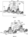
- the parallelogram linkages provided by the row unit coupling device 200 can accommodate such changes in the orientation or profile of the ground surface 272b by allowing, for example, for changes in the angular orientations of the row units 50a, 50b, at least relative to the neutral orientation shown in FIG. 15 .
- Such changes can accommodate the row units 50a, 50b to continue to be positioned to plant seed into the ground in a direction that is generally perpendicular to the adjacent ground surface 272b, which, again, may again assist in the seed being planted at a selected depth.
- the angular orientation of the first and/or second row units 50a, 50b can also be adjusted via rotational displacement of the upper and lower arms 206, 208 about the first and second pivot axes 256a, 256b. Further, in response to rotational displacement of the upper and lower arms 206, 208, the angular orientation of the first and/or second row units 50a, 50b relative to the associated proximal and distal ends 268, 270 of the upper and lower arms 206, 208 can be adjusted via relative pivotal displacement about the associated third, fourth, fifth, and sixth pivot axes 256c-f. Thus, as seen in FIG. 16 , with such adjustments to the angular orientations of the row units 50a, 50b, the row units 50a, 50b are positioned to plant seed a direction that is generally perpendicular to the adjacent ground surface 272b.
- the changes in the compressive state of the biasing element 210 has been accompanied by a displacement of the base unit 202 relative to the mount body 204, which, again, is guided by displacement of the guide arms 228a, 228b of the base unit 202 through the apertures of the mount body 204. Further, to accommodate the differences in vertical positions, the upper and lower arms 206, 208 have been rotated to different extents relative to the leg segment 232 about the first and second pivot axis 256a, 256b.
- Such changes in the angular orientations of the upper and lower arms 206, 208 can also coincide with changes in the angular orientation of the proximal ends 268 of the upper and lower arms 206, 208 relative to the first row unit 50a, which can be facilitated by rotational displacement of the upper and lower arms 206, 208 relative to the first row unit 50a about the third and fourth pivot axes 256c, 256d.
- changes in the angular orientation of the upper and lower arms 206, 208 can also coincide with changes in the angular orientation of the distal ends 270 of the upper and lower arms 206, 208 relative to the second row unit 50b, which can be facilitated by rotational displacement of the upper and lower arms 206, 208 relative to the second row unit 50b about the fifth and sixth pivot axes 256e, 256f.
- the row unit coupling device 200 can at least assist in maintaining the row units 50a, 50b at positions and/or angular orientations at which the row units 50a, 50b can continue to plant seed a direction that is generally perpendicular to the adjacent ground surface 272c.
- FIGS. 19A and 19B illustrate a third embodiment of a row unit coupling device 300.
- the row unit coupling device 300 is configured to couple a pair of row units 50a, 50b to a tool bar 22 in a manner that provides a second parallelogram linkage arrangement.
- the coupling device 300 can be constructed from a variety of materials, including, but not limited to metal and/or steel, among other materials and alloys. Further, according to certain embodiments, the coupling device 300 can be constructed, at least in part, from metallic bars or tubing that can have various cross sectional shapes, and/or can be formed via casting.
- the row unit coupling device 300 includes a mid-arm or base unit 302, one or more main linkages 304, an upper arm 306, and a lower arm 308.
- the upper and lower arms 306, 308 can have a configuration similar to that discussed above with respect to the upper and lower arms 206, 208 of the row unit coupling device 200, and which are depicted in FIGS. 10A-18 .
- the one or more parallel main linkages 304a, 304b comprises an upper main linkage 304a and a lower main linkage 304b.
- the upper and lower main linkages 304a, 304b can be parallel to each other.
- first end 310a of both upper and lower main linkages 304a, 304b, and moreover the first end 310a of each of the first and second linkage segments 312a, 312b of the upper and lower main linkages 304a, 304b can include first upper and lower apertures 316a, 316b, respectively, that can receive first upper and lower pins 318a, 318b ( FIG. 20 ), respectively.
- first upper pin 318a can provide a first pivot point 354a ( FIG. 20 ) that accommodate pivotal displacement of the upper main linkage 304a relative to the tool bar 22 about a first pivot axis 356a ( FIG. 22 ).
- the second lower pin 322b can provide a fourth pivot point 354d ( FIG. 20 ) that can accommodate pivotal displacement of the lower main linkage 304b relative to the base unit 302 about a fourth pivot axis 356d ( FIG. 22 ).
- the third and second pivot axes 356c, 356d can be parallel to, and offset from, each other, as well as parallel and offset from the first and second pivot axes 356a, 356b.
- Such alignment can accommodate insertion of the second upper pin 322a through both the second upper apertures 320a of the first and second segments 312a, 312b of the upper main linkage 304a, and the first upper aperture 328a of the upper portion 324 of the base unit 302 so as to provide a third pivot point 354c ( FIG. 20 ) for the row unit coupling device 300.
- the third pivot point 354c can accommodate rotational displacement of the second end 310a of the upper main linkage 304a relative to the upper portion 324 about a third pivot axis 356c ( FIG. 22 ).
- the lower portion 326 of the base unit 302 can comprise a first leg segment 332a and a second leg segment 332b that are spaced apart to provide a base cavity 344 therebetween that can accommodate displaceable placement of at least a central segment 346 of each of the upper and lower arms 306, 308.
- the first and second leg segments 332a, 332b can downwardly extend from the upper portion 324 of the base unit 302.
- the upper and lower leg pins 352a, 352b can be an integral portion of the upper and lower arms 306, 308, and can extend from opposing sides of the central segment 346 of the associated upper or lower arm 306, 308.
- the upper and lower arms 306, 308 can each include an aperture in the central segment 346 that is sized to receive placement of the associated upper or lower leg pins 352a, 352b.
- the upper leg pin 352a provides a fifth pivot point 354e about which the upper arm 306 can be pivotally displaced along a fifth pivot axis 356e relative to the base unit 302, or vice versa
- the lower leg pin 352b provides a sixth pivot point 354f about which the lower arm 308 can be pivotally displaced along a sixth pivot axis 356f relative to the base unit 302, or vice versa.
- the fifth and sixth pivot axes 356e, 356f can be generally parallel to, and offset from, each other, as well as parallel and offset from the other pivot axes 356a-d.
- first and second offset segments 362, 364 can extend in opposing outwardly directions.
- one of the first and second offset segments 362, 364 can outwardly extend in a generally right side direction relative to the sidewalls 348a, 348b of the central segment 346, and the other of the first and second offset segments 362, 364 outwardly extend in an, opposing, generally left side direction.
- At least a portion of the first, proximate row unit 50a is positioned upstream of, or positioned at a more forward location relative to the direction the seeder 10 will travel while performing a seeding operation, than the second, distal row unit 50b.
- Each of the proximal and distal segments 358, 360 are configured to be pivotally secured to a row unit 50a, 50b.
- the ends of each of the upper and lower arms 306, 308 can include a row unit pin 366 that can be received in a mating aperture in an associated row unit 50a, 50b, and/or a mounting plate or bracket that is secured to the row unit 50a, 50b.
- the opposing ends of the upper and lower arms 306, 308 can each include an aperture that can accommodate receipt of a mating row unit pin 366 that is part of, or otherwise coupled to or received by, the associated row unit 50a, 50b, and/or an associated mounting plate or bracket that is secured to the row unit 50a, 50b.
- the proximal ends 368 of the upper and lower arms 306, 308 can be pivoted, relative to the first row unit 50a, or vice versa, at or around seventh and eight pivot points 354g, 354h about associated seventh and eight pivot axes 356g, 356h, respectively.
- distal ends 370 of the upper and lower arms 306, 308 can be pivoted, relative to the second row unit 50b, or vice versa, at or around ninth and tenth pivot points 354i, 354j about associated ninth and tenth pivot axes 356i, 356j, respectively.
- FIG. 23 illustrates an example in which the adjacent ground surface 372a upon which the row units 50a, 50b are traveling is relatively flat, but is elevated relative to the portion of the ground surface 372a along which wheels 348 of the seeder 10 are traveling.
- the increased elevation of the row units 50a, 50b in FIG. 23 can facilitate a raising of the upper and lower arms 306, 308 that are coupled to the row units 50a, 50b.
- the upper and lower arms 306, 308 are coupled to the base unit 302, such upward displacement of the upper and lower arms 306, 308 facilitates the base unit 302 also being raised in the vertical direction.
- the upper and lower main linkages 304a, 304b which can be parallel to each other, are pivoted in similar manners relative to both the base unit 302 and the tool bar 22.
- the upper and lower main linkages 304a, 304b have been rotated in a first, clockwise direction at the first, second, third, and fourth pivot points 354a-d, and about the corresponding first, second, third, and fourth pivot axes 356a-d.
- the upper and lower linkages 304a, 304b can be rotated about the corresponding first, second, third, and fourth pivot points 354a-d in the second, counterclockwise rotational direction such that the second ends 310b of the upper and lower linkages 304a, 304b are at a higher vertical height than the first ends 310a of the upper and lower linkages 304a, 304b.
- the upper and lower linkages 304a, 304b can retain a relatively parallel orientation with respect to each other.
- While the upper and lower linkages 304a, 304b in the example provided by FIG. 25 can be rotated in the second, counterclockwise rotational direction to at least accommodate the lowering of the base unit 302, the upper and lower arms 306, 308 can be rotated in the first, clockwise rotational direction. Accordingly, such rotation of the upper and lower arms 306, 308 can occur at the fifth and sixth pivot points 354e, 354f.
- the proximal and distal ends 368, 370 of the upper and lower arms 306, 308 can accommodate changes in the angular orientation of the row units 50a, 50b relative to the upper and lower arms 306, 308.
- the angular orientation of the row units 50a, 50b can be change at the associated seventh, eighth, ninth, and tenth pivot points 354g-j relative to the upper and lower arms 306, 308.
- the first row unit 50a is at a higher vertical height than the second row unit 50b.
- the upper and lower linkages 304a, 304b have been rotated about the first, second, third, and fourth pivot points 354a-d in the first, clockwise rotational direction such that the second ends 310b of the upper and lower linkages 304a, 304b are at a lower vertical height than the first ends 310a of the upper and lower linkages 304a, 304b.
- the upper and lower linkages 304a, 304b can retain a relatively parallel orientation with respect to each other. While the upper and lower linkages 304a, 304b in the example provided by FIG.
- the first and second lower arm segments 406a, 406b can have a similar tongue and groove construction, among other manners of being pivotally coupled at the same location.
- the lower leg pin 418b can extend through similar apertures 428 in the first ends 422 of the first and second lower arm segments 406a, 406b, as well as into the adjacent lower leg apertures 416b in the leg segments 412a, 412b of the lower portion 410 of the base unit 402.
- Such an arrangement can thus similarly accommodate pivotal displacement of the first lower arm segment 406a being independent of the second lower arm segment 406b, as well as the second lower arm segment 406b being pivotally displaceable independent of the first lower arm segment 406a.
Landscapes
- Life Sciences & Earth Sciences (AREA)
- Soil Sciences (AREA)
- Environmental Sciences (AREA)
- Engineering & Computer Science (AREA)
- Mechanical Engineering (AREA)
- Agricultural Machines (AREA)
- Sowing (AREA)
Abstract
Description
- The present disclosure generally relates to agricultural planters, and, more specifically, to devices for arranging pairs of seeding row units for agricultural planters.
- Agricultural planters, such as multi-row crop planters, are typically pulled by a tractor, or other work vehicle, and can plant seeds at a selected depth within a trench formed in the soil. The depth at which seed is to be planted in the ground can be set for each row unit, such as, for example, via a mechanical depth adjustment mechanism. Such a depth setting can be based on a variety of different criteria, including, for example, the seed type and environmental conditions, such as, for example, soil composition, moisture levels, and weather predictions, among other considerations.
- The row units of the multi-row crop planters are typically designed to be aligned substantially parallel to the travel direction of the tractor when being pulled through a field. Further, the selected depth at which seed is to be planted is often based, at least in part, on the premise that the planting of the seed via a row unit will occur in a direction in which the row unit is generally perpendicular to the adjacent ground surface. However, undulations in the ground surface along which row units travel can result in deviations in the actual depths at which the row units plant seeds. For example, variances in terrain of a field can result in a lifting or tilting of row units, which can prevent seeds from reaching selected planting depths. Additionally, such lifting or tilting of row units can adversely impact the spacing between adjacent seeds that are planted by a row unit.
- Row units of a row crop planter are also typically positioned in a side-by-side arrangement wherein each row unit is downstream from an adjacent tool bar of the planter by about the same distance. Thus, the distance between the trenches in which each row unit plants seeds, and thus the distance separating the resulting crop rows, can be at least partially dependent on how close the row units can physically be positioned next to each other. Yet, such an arrangement can adversely impact the ability to provide relatively narrow spacing between crop rows.
- What is needed therefore are seeding planters in which row units have enhanced ground following capabilities, and that can also accommodate relatively narrow crop row spacing.
- The present disclosure may comprise one or more of the following features and combinations thereof.
- In one embodiment, a row unit coupling device for securing a first row unit and a second row unit to a tool bar of an agricultural implement comprises a mount body adapted to be coupled to the tool bar and a base unit that is slidingly coupled to the mount body, the base unit having a leg segment. The row unit coupling device further includes a biasing element that can be positioned to provide a biasing force to bias the base unit in a downward direction relative to the mount body, an upper arm, and a lower arm. The upper arm is pivotally coupled to the leg segment to rotate about a first axis of rotation, and can have an upper central segment, an upper proximal end, and an upper distal end. The upper proximal and distal ends are at opposing ends of the upper arm and offset from each other in a direction that is parallel to the first axis of rotation. Additionally, the upper proximal end is adapted for pivotal coupling to the first row unit, and the upper distal end is configured for pivotal coupling to the second row unit. The lower arm is pivotally coupled to the leg segment to rotate about a second axis of rotation, and has a lower central segment, a lower proximal end, and a lower distal end. The lower proximal and distal ends are at opposing ends of the lower arm and offset from each other in a direction that is parallel to the second axis of rotation. Further, the lower proximal end is adapted for pivotal coupling to the first row unit, and the lower distal end is configured for pivotal coupling to the second row unit.
- In another embodiment of the present disclosure, a row unit coupling device for securing a first row unit and a second row unit to a tool bar of an agricultural implement can comprise a swing arm and a walking beam, the swing arm having a first end and a second end, the first end configured for pivotal coupling to the tool bar. The walking beam can have a central beam, a first row adapter, and a second row adapter. The central beam can have a proximal end and a distal end. The first row adapter and the second row adapter can be secured to the central beam on opposing sides of a position at which the swing arm is pivotally coupled to the central beam. Additionally, the first row adapter can be configured to be coupled to the first row unit, and the second row adapter can be configured to be coupled to the second row unit.
- In a further embodiment of the present disclosure, a row unit coupling device for securing a first row unit and a second row unit to a tool bar of an agricultural implement can comprise an upper main linkage and a lower main linkage. The upper main linkage can have a first end and a second end, the second end of the upper main linkage configured to be pivotally coupled to the tool bar. The lower main linkage can have a first end and a second end. The second end of the lower main linkage can be configured to be pivotally coupled to the tool bar, and can be positioned below, and parallel to, the upper main linkage. The row unit coupling device can also include a base unit, an upper arm, and a lower arm. The base unit can have an upper portion and a lower portion, the upper portion being pivotally coupled to the first end of the upper main linkage and the first end of the lower main linkage. The upper arm can be pivotally coupled to a lower portion of the base unit to rotate about a first axis of rotation. Further, the upper arm can have an upper central segment, an upper proximal end, and an upper distal end. The upper proximal and distal ends can be at opposing ends of the upper arm and offset from each other in a direction that is parallel to the first axis of rotation. Additionally, the upper proximal end can be adapted for pivotal coupling to the first row unit, and the upper distal end can be configured for pivotal coupling to the second row unit. The lower arm can be pivotally coupled to the lower portion of the base unit to rotate about a second axis of rotation. The lower arm can have a lower central segment, a lower proximal end, and a lower distal end. The lower proximal and distal ends can be at opposing ends of the lower arm and offset from each other in a direction that is parallel to the second axis of rotation. Additionally, the lower proximal end can be adapted for pivotal coupling to the first row unit, and the lower distal end can be configured for pivotal coupling to the second row unit.
- In another embodiment, a row unit coupling device for securing a first row unit and a second row unit to a tool bar of an agricultural implement can comprise a base unit having an upper portion and a lower portion, the upper portion being configured for coupling to the tool bar. The row unit coupling device can also include an upper arm and a lower arm, the upper arm comprising a first upper arm segment and a second upper arm segment. The first upper arm segment can extend to an upper proximate end of the upper arm, and the second upper arm segment can extend to an upper distal end of the upper arm. Additionally, the first upper arm segment can be pivotally coupled to the base unit to rotate about a first axis, and the second upper arm segment can be pivotally coupled to the base unit to rotate, independent of rotation of the first upper arm segment, about a second axis that may, or may not, be positioned along the first axis. The upper proximal and distal ends can be at opposing ends of the upper arm and offset from each other in a direction that is parallel to the first axis of rotation.
- Additionally, the upper proximal end can be adapted for pivotal coupling to the first row unit, and the upper distal end can be configured for pivotal coupling to the second row unit. The lower arm can comprise a first lower arm segment and a second lower arm segment, the first lower arm segment extending to a lower proximate end of the lower arm, and the second lower arm segment extending to a lower distal end of the lower arm. The first lower arm segment can be pivotally coupled to the base unit to rotate about a third axis. The second lower arm segment can be pivotally coupled to the base unit to rotate, independent of rotation of the first lower arm segment, about a fourth axis that may, or may not, be positioned along the third axis. Additionally, the lower proximal and distal ends can be at opposing ends of the lower arm and offset from each other in a direction that is parallel to the third axis of rotation. Additionally, the lower proximal end can be adapted for pivotal coupling to the first row unit, and the lower distal end can be configured for pivotal coupling to the second row unit.
- These and other features of the present disclosure will become more apparent from the following description of the illustrative embodiments.
- The invention described herein is illustrated by way of example and not by way of limitation in the accompanying figures. For simplicity and clarity of illustration, elements illustrated in the figures are not necessarily drawn to scale. For example, the dimensions of some elements may be exaggerated relative to other elements for clarity. Further, where considered appropriate, reference labels have been repeated among the figures to indicate corresponding or analogous elements.
-
FIG. 1 illustrates an exemplary agricultural seeder in the form of a row crop planter being pulled by an agricultural machine along a field; -
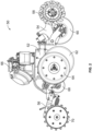
FIG. 2 illustrates an exemplary row unit that can be used with the agricultural seeder shown inFIG. 1 ; -
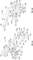
FIGS. 3A and 3B illustrate an exploded view and perspective view, respectively, of a first embodiment of a row unit coupling device not forming part of the claimed invention; -
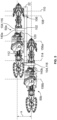
FIGS. 4-6 illustrate side, top, and perspective views, respectively, of the row unit coupling device shown inFIGS. 3A and 3B coupled to a pair of row units; -
FIGS. 7-9 illustrate side views of the row unit coupling device and row units shown inFIGS. 4-6 coupled to a tool bar and being pulled across various undulations in a ground surface; -
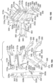
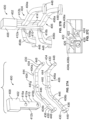
FIGS. 10A and10B illustrate an exploded view and perspective view, respectively, of an embodiment of a row unit coupling device forming part of the invention as claimed; -
FIG. 11 illustrates a side view of the row unit coupling device shown inFIGS. 10A and10B coupled to a pair of row units; -
FIG. 12 illustrates a top view of an upper arm or a lower arm of the row unit coupling device shown inFIGS. 10A and10b ; -
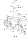
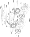
FIGS. 13 and14 illustrate a top view and a perspective view, respectively, of the row unit coupling device shown inFIGS. 10A-10B coupled to a pair of row units; -
FIGS. 15-18 illustrate side views of the row unit coupling device and row units shown inFIGS. 11 ,13 , and14 coupled to a tool bar and being pulled across various undulations in a ground surface; -
FIGS. 19A and 19B illustrate an exploded view and perspective view, respectively, of a third embodiment of a row unit coupling device not forming part of the claimed invention; -
FIGS. 20-22 illustrate side, top, and perspective views, respectively, of the row unit coupling device shown inFIGS. 19A and 19B coupled to a pair of row units; -
FIGS. 23-26 illustrate side views of the row unit coupling device and row units shown inFIGS. 20-22 coupled to a tool bar and being pulled across various undulations in a ground surface; -
FIGS. 27A and 27B illustrate an exploded view and perspective view, respectively, of a fourth embodiment of a row unit coupling device not forming part of the claimed invention; -
FIG. 27C illustrates a perspective view of portions of exemplary first ends of the first and second upper or lower arm segments; -
FIGS. 28-30 illustrate side, top, and perspective views, respectively, of the row unit coupling device shown inFIGS. 27A and 27B coupled to a pair of row units; and -
FIGS. 31-34 illustrate side views of the row unit coupling device and row units shown inFIGS. 28-30 coupled to a tool bar and being pulled across various undulations in a ground surface. - Corresponding reference numerals are used to indicate corresponding parts throughout the several views.
- It is noted that
FIGS. 3A to 9 ,FIGS. 19A to 26 andFIGS. 27A to 34 relate to examples which are shown for exemplary reasons and which are not examples forming part of the claimed invention. The claimed invention is rather explained by referencing toFIGS 1 ,2 and10A to 18. - While the concepts of the present disclosure are susceptible to various modifications and alternative forms, specific embodiments thereof have been shown by way of example in the drawings and will be described herein in detail. It should be understood, however, that there is no intent to limit the concepts of the present disclosure to the particular forms disclosed, but on the contrary, the intention is to cover all modifications, equivalents, and alternatives consistent with the present disclosure and the appended claims.
- References in the specification to "one embodiment," "an embodiment," "an illustrative embodiment," etc., indicate that the embodiment described may include a particular feature, structure, or characteristic, but every embodiment may or may not necessarily include that particular feature, structure, or characteristic. Moreover, such phrases are not necessarily referring to the same embodiment. Further, when a particular feature, structure, or characteristic is described in connection with an embodiment, it is submitted that it is within the knowledge of one skilled in the art to effect such feature, structure, or characteristic in connection with other embodiments whether or not explicitly described. Additionally, it should be appreciated that items included in a list in the form of "at least one A, B, and C" can mean (A); (B); (C); (A and B); (A and C); (B and C); or (A, B, and C). Similarly, items listed in the form of "at least one of A, B, or C" can mean (A); (B); (C); (A and B); (A and C); (B and C); or (A, B, and C).
- In the drawings, some structural or method features may be shown in specific arrangements and/or orderings. However, it should be appreciated that such specific arrangements and/or orderings may not be required. Rather, in some embodiments, such features may be arranged in a different manner and/or order than shown in the illustrative figures. Additionally, the inclusion of a structural or method feature in a particular figure is not meant to imply that such feature is required in all embodiments and, in some embodiments, may not be included or may be combined with other features.
- A number of features described below may be illustrated in the drawings in phantom. Depiction of certain features in phantom is intended to convey that those features may be hidden or present in one or more embodiments, while not necessarily present in other embodiments. Additionally, in the one or more embodiments in which those features may be present, illustration of the features in phantom is intended to convey that the features may have location(s) and/or position(s) different from the locations(s) and/or position(s) shown.
FIG. 1 illustrates an exemplaryagricultural seeder 10, and moreover aseeder 10 in the form of a row crop planter according to the invention as claimed. A work vehicle in the form of atractor 12 can be coupled with, and moves, theseeder 10 with a suitable coupling arrangement, such as, for example, a draw bar or 3-point hitch arrangement 11. Other embodiments however are contemplated, including an autonomous tractor pulling theseeder 10, as well as an entirely self-contained autonomous seeder in which the seeder, including the row units and a propulsion system for the seeder, are a complete and unitary seeding system. - The illustrated
seeder 10 includes a plurality ofrow units 14. According to certain embodiments, eachrow unit 14 can have a substantially identically configured. Eachrow unit 14 can be configured to deposit seeds of varying sizes inrespective furrows 18, not all of which are illustrated, in the soil for raising crops. In some embodiments, two or more of therow units 14 are configured to deposit seeds of different sizes and/or seeds for different crop types. Typically, however, the size of the seeds being deposited is the same for eachrow unit 14. In other embodiments, seeds of different sizes may be deposited side by side in adjacent rows at different planting depths, which can depend on the size of the seed. - A plurality of
seed bins 20 can be operatively connected to each of therow units 14, and are configured to hold seeds for planting. In other embodiments, a single seed bin is used to supply seeds to allrow units 14. In operation, eachseed bin 20 can hold the same type of seeds or different types of seeds, which may be directed to each of therow units 14, as necessary. Atool bar 22 can extend, and is coupled, to each of therow units 14 to maintain a predetermined spacing betweenfurrows 18. In some embodiments, a rockshaft may be located over or above thetool bar 22. In some embodiments, the spacing betweenrow units 14 is adjustable to provide for crops of different types that require spacing betweenfurrows 18 based on the type of seed. - While the
exemplary seeder 10 shown inFIG. 1 illustrates each of therow units 14 being in a side-by-side arrangement in which therow units 14 are generally in a parallel arrangement and/or at about a same distance from thetool bar 22, embodiments discussed herein can accommodate a staggering in the alignment of adj acentrow units 14. For example, according to certain embodiments discussed below, a row units 14 (FIG. 2 ) can be positioned further upstream of an adjacent or neighboringrow unit 14. In some instances, such a staggered alignment can result in arow unit 14 being in closer proximity to thetool bar 22 thanadjacent row units 14. Additionally, with respect to some embodiments, such a staggered alignment can result in at least a portion of one row unit being one side of thetool bar 22, such as, for example, an upstream orproximate side 28 of thetool bar 22, while anadjacent row unit 14 can be positioned on the other, or downstream ordistal side 26 of thetool bar 22. Such a staggered alignment ofrow units 14 can be configured such that narrower porti ons ofadjacent row units 14 are directly adjacent to each other, and/or wider portions of arow unit 14 are adjacent to a narrower portion of anadjacent row unit 14. By providing such a staggered alignment in which wider portions of adjacent row units are offset from each other in at least a direction of travel of therow units 14,adjacent row units 14 can be positioned in closer proximity with each other, thereby providing the capability to reduce the spacing betweenfurrows 18, and accommodate the planting of seeds at locations that provide relatively narrow crop spacing. -
FIG. 2 illustrates anexemplary row unit 50 that can, along with other types ofrow units 14, be utilized with embodiments of the subject application. The illustratedrow unit 50 includes acentral frame 52 that is pivotally coupled to afront frame arm 54 and arear frame arm 56. Thefront frame arm 54 in the illustratedexemplary row unit 50 can be coupled to a pair ofrow cleaners 58 and acoulter blade 60. Thecentral frame 52 can be coupled to adisc 62, also known as a blade, shank, knife, or a cutting device or member. Thedisc 62 can extend inwardly into the ground at least until one ormore gage wheels 64, also known as a depth-gaging or surface following device or member, engages the soil. According to the illustratedrow unit 50,gage wheels 64 are positioned on opposing sides of thedisc 62. Additionally, with respect to at least certain types of row units, the relationship between thegage wheels 64 and thedisc 62 can be adjusted so as to at least assist in adjusting a depth to which therow unit 50 deposits seeds in the adjacent soil. According to certain embodiments, seed that is received at or around ahopper 66 of therow unit 50 can travel through at least a portion of therow unit 50 before being deposited from therow unit 50 at or around a base of thedisc 62. Therow unit 50 can include apress wheel 68 downstream of the location at which therow unit 50 is to deposit seed into the soil. Further, therear frame arm 56 in the illustrated row unit is depicted as being coupled to a pair of closingwheels 70. -
FIGS. 3A and 3B illustrate a first embodiment of a rowunit coupling device 100. As seen in at leastFIGS. 4-8 , the rowunit coupling device 100 is configured to couple a pair ofrow units tool bar 22 in a manner that provides a walking beam arrangement. Thecoupling device 100 can be constructed from a variety of materials, including, but not limited to metal and/or steel, among other materials and alloys. Further, according to certain embodiments, thecoupling device 100 can be constructed, at least in part, from metallic bars or tubing that can have various cross sectional shapes, and/or can be formed via casting. - According to the illustrated embodiment, the row
unit coupling device 100 incudes aswing arm 102 and awalking beam 104. Theswing arm 102 is configured to be pivotally coupled to thetool bar 22 at a first pivot point 106 (FIG. 4 ) of thecoupling device 100 such that theswing arm 102 can be pivotally displaced about a first axis 108 (FIG. 5 ) at thefirst pivot point 106. As seen inFIG. 5 , according to the illustrated embodiment, thefirst axis 108 extends in a direction that is generally parallel to a centrallongitudinal axis 110 of thetool bar 22 that extends along the width of thetool bar 22, and is in a direction that is generally perpendicular to the direction in which thetractor 12 will pull theseeder 10 while planting seed. Further, thefirst axis 108 may, or may not, be offset from thecentral axis 110 of thetool bar 22, including in one or both of a horizontal direction and vertical direction. - The
walking beam 104 can be pivotally coupled to theswing arm 102 at a second pivot point 112 (FIG. 4 ) of thecoupling device 100. Thus, thewalking beam 104 can be pivotally displaceable relative to theswing arm 102, and vice versa, about asecond axis 114 at thesecond pivot point 112. As seen inFIG. 5 , thesecond axis 114 is generally parallel to, and offset from, both thefirst axis 108 and thecentral axis 110 of thetool bar 22 in one or both of a horizontal direction and vertical direction. - Pivotal displacement of the
swing arm 102 about thefirst axis 108 of thefirst pivot point 106 can result in a vertical raising or lowering of at least a portion of thewalking beam 104 relative to at least thetool bar 22. Such vertical raising and lowering of thewalking beam 104 can result in a raising or lowering of one or both of first andsecond row units FIG. 4-6 ) that are coupled to thewalking beam 104. Similarly, rotation of thewalking beam 104 about thesecond axis 114 of thesecond pivot point 112 can result in a change in the vertical position of proximal anddistal ends walking beam 104. Moreover, as thewalking beam 104 is pivotally displaced, one of the proximal anddistal ends walking beam 104, and therow unit end distal ends walking beam 104, and therow unit end - As seen in at least
FIGS. 3A and 3B , theswing arm 102 includes afirst arm 120 that extends in a first direction, asecond arm 122 that extends in second direction, the second direction being different than the first direction. According to certain embodiments, the first direction can be a generally horizontal direction, while the second direction can be a generally vertical direction. Further, according to the illustrated embodiment, the first direction is generally perpendicular to the second direction. Additionally, according to certain embodiments, theswing arm 102 can include anelbow portion 124 that joins thefirst arm 120 to thesecond arm 122, and which can provide a transition between the first direction and the second direction. - The
first arm 120 of theswing arm 102 can extend from afirst end 126 of theswing arm 102 to theelbow portion 124 of theswing arm 102. Thefirst end 126 is adapted to couple the rowunit coupling device 100 to thetool bar 22. For example, according to certain embodiment, thefirst end 126 of the first portion of theswing arm 102 includes anaperture 130 that is sized to receive a first pin 132 (FIG. 4 ) that can pivotally couple, or attach, thefirst arm 120, and thus theswing arm 102, to thetool bar 22. Such a pivotal connection can provide the previously mentionedfirst pivot point 106 for the rowunit coupling device 100. The length of thefirst arm 120 between thefirst end 126 and theelbow portion 124 can be based on a variety of criteria. For example, according to certain embodiments, thefirst arm 120 can have a length that will separate a first, forward positionedrow unit 50a from contacting thetool bar 22 as a vertical position, and/or angular orientation, of thefirst row unit 50a relative to thetool bar 22 is changed in response to pivotal displacement of at least the rowunit coupling device 100 and/or therow units FIG. 5 ). Additionally, or alternatively, according to certain embodiments, thefirst arm 120 can have a length that can accommodate the first andsecond row units seeder 10 is in a transport mode. For example, according to certain embodiments, thefirst arm 120 can have a length such that when at least thefirst arm 120 is rotated about ninety degrees from the position shown inFIG. 7 , both therow units adjacent ground surface 166a-c (FIGS. 7-9 ). - The
second arm 122 of theswing arm 102 can extend from theelbow portion 124 to asecond end 128 of theswing arm 102. Thesecond arm 122 can include, in relatively close proximity to thesecond end 128, anaperture 134 that can receive a second pin 136 (FIG. 4 ) that can pivotally couple theswing arm 102 to thewalking beam 104. Such a pivotal connection between theswing arm 102 and thewalking beam 104 can provide the rowunit coupling device 100 with thesecond pivot point 112 about which theswing arm 102 and/or thewalking beam 104 can be pivotally displaced. - The
walking beam 104 has acentral beam 138 that extends between aproximal end 116 and adistal end 118 of thewalking beam 104. Arow adapter row unit unit coupling device 100 can outwardly extend from each of the opposing proximal anddistal ends walking beam 104. According to certain embodiments, eachrow adapter central beam 138 in a direction that is generally perpendicular to thecentral beam 138, and which is also generally parallel to thetool bar 22 Additionally, as seen in at leastFIGS. 3A and 3B , therow adapters central beam 138 in opposite directions so as to accommodate an partially overlapping side-by-side placement ofadjacent row units unit coupling device 100, as seen for example in at leastFIG. 5 . - The
row adapters connection body 142 and an offsetbody 144. Eachconnection body 142 is adapted to secure arow unit unit coupling device 100. For example, according to certain embodiments, theconnection body 142 includes a plurality of through-holes 146 that can accommodate passage of a mechanical faster, such as, for example, a bolt and/or screw, that can mechanically fasten or attach thecentral frame 52 of arow unit connection body 142. Theconnection body 142 can also include one or more threadedapertures 148 that can threadingly receive a mechanical faster that can further secure thecentral frame 52, among other portions, of therow unit unit coupling device 100. - As seen in at least
FIGS. 3A and 3B , according to certain embodiments, theconnection body 142 can include anupper portion 150 and alower portion 152 that are connected via astem segment 154 of theconnection body 142. Thestem segment 154 can extend vertically between the upper andlower portions second axis 114 that is narrower then at least thelower portion 152. Further, according to the illustrated embodiment, theupper portion 150 can include a plurality of the through-holes 146, while thelower portion 152 can include at least some of the threadedapertures 148. However, the positioning of the through-holes 146 and/or threadedapertures 148 can be dependent, at least in part, on the associated positioning of through-holes and/or threaded apertures in thecentral frame 52 and/or an associated mounting bracket that may accommodate indirect attachment of therow unit corresponding connection body 142. - The offset
body 144 of eachrow adapter central beam 138 and the associatedconnection body 142. The offsetbody 144 can have a length between thecentral beam 138 and theconnection body 142 that can accommodate arow unit connection body 142 without, or with minimal, interference from theother row unit body 144 can assist with the rowunit coupling device 100 being configured to accommodate the widths of therow units row units FIG. 5 ). - For example, as seen in
FIG. 5 , thecentral frames 52 of therow units unit coupling device 100 can be offset from each other such the center of gravity and/or thecentral frame 52 of the first, or proximal,row unit 50a is positioned between the proximal anddistal ends walking beam 104, and, moreover, located upstream of theconnection body 142 at thedistal end 118. Further, the center of gravity and/or thecentral frame 52 of the second, or distal,row unit 50b is positioned downstream of theconnection body 142 that is at thedistal end 118. Such an overlapping arrangement can result in thecentral frame 52 of the first,proximate row unit 50a being positioned upstream, and not neighboring, thecentral frame 52 of the second,distal row unit 50b. Thus, for example, acenterline 156a of thefirst row unit 50a that is generally parallel to thetool bar 22 can be upstream, and in a horizontal direction, from asimilar centerline 156b of thesecond row unit 50b. Further, according to certain embodiments, thecenterlines row units row units second pivot point 112. Additionally, or alternatively, the centers of reaction force for the proximal anddistal row units second pivot point 112. Such centers of reaction force can, for example, be based, at least in part, on the downward force settings and/or requirements of the associatedopener blades 62,row cleaners 58,coulter blades 60,press wheels 68,gage wheels 64, and/or closingwheels 70, among other configurations and/or setting of therow units distal row units row unit other row unit - As also seen in at least
FIGS. 3A and 3B , thecentral beam 138 can also include a pair of opposing proximal anddistal support protrusions cavity 164 that can house at least a portion of thesecond end 128 of theswing arm 102. According to certain embodiments, the proximal anddistal support protrusions top surface 162 of thecentral beam 138 and have generally curve shaped inner surfaces, among other configurations, that can accommodate rotation of thesecond end 128 of theswing arm 102 as theswing arm 102 and/or thewalking beam 104 are rotated about thesecond pivot point 112. The sidewalls 160a, 160b can each include anaperture 166 that can receive insertion of thesecond pin 136, and can be positioned to maintain a relative alignment of theswing arm 102 and thewalking beam 104 during at least pivotal displacement about thesecond pivot point 112. -
FIGS. 7-9 illustrate exemplary orientations of the rowunit coupling device 100 in response to changes in the profile of the adjacent ground surface(s) 166a-c along which one or each of therow units seeder 10, and/ortractor 12 are traveling. As seen inFIG. 7 , while traveling along a relatively flat,horizontal ground surface 166a, thetool bar 22 is at a vertical orientation or position that is generally perpendicular to theadjacent ground surface 166a. Further, in this scenario, both theswing arm 102 andwalking beam 104 are at generally neutral positions wherein thefirst arm 120 of theswing arm 102 and thecentral beam 138 of thewalking beam 104 are generally parallel to each other and/or to theground surface 166a. In such an orientation, therow units adjacent ground surface 166a, which may thereby assist in the seed being planted at a selected depth. - In
FIG. 8 , the first andsecond row units ground surface 166b. As seen, in such a situation, the positioning of therow units ground surface 166b can facilitate theswing arm 102 being pivotally displaced in a first, clockwise rotation direction such that theswing arm 102 is generally raised in an upward direction about thefirst pivot point 106, including relative to thetool bar 22. Further, in the illustrated example, theelbow portion 124 of theswing arm 102, and thus at least the portion of thefirst arm 122 that is adjacent to theelbow portion 124, has thus been raised to a vertical height that is higher than a vertical height of thefirst end 126 of theswing arm 102. Such pivotal displacement of theswing arm 102 can also coincide with, or facilitate, a vertical raising of thewalking beam 104 at least at the location at or around thesecond pivot point 112, and at least relative to thetool bar 22 and/orfirst pivot point 106. - Additionally, in the example depicted in
FIG. 8 , thewalking beam 104 is also pivoted in the first, clockwise rotational direction such that theproximal end 116 of thewalking beam 104 is lowered in a vertical direction, while the opposingdistal end 118 of thewalking beam 104 is raised in a vertical direction, about thesecond pivot point 112. Such displacement of thewalking beam 104 in the first, clockwise rotational direction can result in similar rotational displacement of the attached first andsecond row units FIG. 7 , as seen inFIG. 8 , such rotational displacement about the first and second pivot points 106, 112 can result a distance between thefirst end 126 of theswing arm 102 and theproximal end 116 of thewalking beam 104 decreasing, as well as thedistal end 118 of thewalking beam 104 raising to a vertical height that is higher than at least theproximal end 116 of thewalking beam 104. By at least the rowunit coupling device 100 being pivotal about the first and second pivot points 106, 112, the first andsecond row units tool bar 22 in manners that can accommodate changes in the profile or orientation of theground surface 166b. Such changes can generally accommodate therow units ground surface 166b, and thereby generally continue seed planting seed at a selected depth. Further, such adjustments in the angular orientations of therow units unit coupling device 100 can occur while other row units of theseeder 10 that are coupled to other rowunit coupling devices 100 are traveling along a flat,horizontal ground surface 166a, or ground surfaces having other orientations, such as, for example, the ground surfaces discussed below with respect toFIG. 9 . - In
FIG. 9 , the first andsecond row units ground surface 166c. As seen, in such a situation, the first andsecond row units ground surface 166c can facilitate theswing arm 102 being pivotally displaced in a second, counterclockwise rotation direction that is opposite of the first rotational direction such that theswing arm 102 is generally lowered about thefirst pivot point 106, including relative to thetool bar 22. Further, in the illustrated example theelbow portion 124, and thus adjacent portion of thefirst arm 120, of theswing arm 102 are lowered to vertical heights that are lower than a vertical height of thefirst end 126 of theswing arm 102. Such pivotal displacement of theswing arm 102 can also lower thewalking beam 104 at least at the location at or around thesecond pivot point 112, and at least relative to thetool bar 22 and/orfirst pivot point 106. - Further, in the example depicted in
FIG. 9 , thewalking beam 104 is also pivoted in the second, counterclockwise rotational direction such that theproximal end 116 of thewalking beam 104 is raised in a vertical direction, while the opposingdistal end 118 of thewalking beam 104 is lowered in a vertical direction, about thesecond pivot point 112. Such displacement of thewalking beam 104 in the second, counterclockwise rotational direction can result in similar rotational displacement of the attached first andsecond row units FIG. 7 , as seen inFIG. 9 , such rotational displacement about the first and second pivot points 106, 112 can also result a distance between thefirst end 126 of theswing arm 102 and theproximal end 116 of thewalking beam 104 increasing, as well as thedistal end 118 of thewalking beam 104 raising to a vertical height that is lower than at least theproximal end 116 of thewalking beam 104. However, regardless of the direction or extent of displacement about the first and second pivot points 106, 112, as withFIG. 8 , the adjustments in the angular orientations of therow units unit coupling devices 100, as seen inFIG. 9 , allows for therow units adjacent ground surface 166c, which may thereby assist in the seed being planted at a selected depth. -
FIGS. 10A and10B illustrate a second embodiment of a rowunit coupling device 200. As seen in at leastFIGS. 11-18 , the rowunit coupling device 200 is configured to couple a pair ofrow units tool bar 22 in a manner that provides a first parallelogram linkage arrangement. Thecoupling device 200 can be constructed from a variety of materials, including, but not limited to metal and/or steel, among other materials and alloys. Further, according to certain embodiments, thecoupling device 200 can be constructed, at least in part, from metallic bars or tubing that can have various cross sectional shapes, and/or can be formed via casting. - According to the illustrated embodiment, the row
unit coupling device 200 includes a mid-arm orbase unit 202, amount body 204, anupper arm 206, alower arm 208, and abiasing element 210, such as, for example, a spring, among other biasing elements. Themount body 204 is adapted to be securely connected to thetool bar 22. Themount body 204 can include atop wall 212, abottom wall 214, afront wall 216, and a rear wall 218 (FIG. 13 ). According to the illustrated embodiment, themount body 204 includes anorifice 220 that extends through the front andrear walls tool bar 22. Theorifice 220 can further extend along acenterline 222 that is generally parallel to the centerline of at least the portion of thetool bar 22 that extends through theorifice 220. Themount body 204 can also comprise two sections orhalves tool bar 22, and that can be joined together, such as, for example, via one or more mechanical fasteners, so as to secure themount body 204 about thetool bar 22. As also seen in at leastFIG. 10A , themount body 204 can include a pair ofapertures bottom walls mount body 204 that are each adapted to receive the slideable displacement of aguide arm base unit 202. According to the illustrated embodiments, theapertures mount body 204, as well as on opposing sides of theorifice 220. Displacement of theguide arms apertures base unit 202 and the upper andlower arms - In addition to the
guide arms base unit 202 can further include acentral beam 230 and aleg segment 232. According to the illustrated embodiment, theguide arms central beam 230, such as, for example, from anupper wall 234 of thecentral beam 230. Additionally, thecentral beam 230 can extend between afirst end 236 and asecond end 238 in a direction that is generally perpendicular to thecenterline 222 of theorifice 220 of themount body 204 and to the upwardly extending direction of theguide arms central beam 230 at least along theupper wall 234 is greater than a corresponding width between opposingsides mount body 204. Thecentral beam 230 also has a thickness between theupper wall 234 and an opposinglower wall 242 of thecentral beam 230 so as to at least assist in preventing and/or minimizing the deflection, deformation, and/or bending of thecentral beam 230 that may be attributed to the biasingelement 210 exerting at least a downward force against thecentral beam 230 and/or forces associated with direct or indirect coupling between thecentral beam 230 and therow units - The
leg segment 232 comprises afirst leg segment 232a and asecond leg segment 232b that are spaced apart to provide acavity 244 therebetween that can accommodate displaceable placement of at least acentral segment 246 of each of the upper andlower arms FIGS. 10A and10B , the first andsecond leg segments central beam 230 in a direction that is generally opposite, and can be parallel, to the upwardly direction in which theguide arms central beam 230. Additionally, according to the illustrated embodiment, the first andsecond leg segments FIG. 13 ) of thecentral beam 230 and/or from thelower wall 242 of thecentral beam 230. The first andsecond leg segments lower apertures lower pin - As seen in at least
FIG. 10B , the upper andlower arms second leg segments upper pin 252a andlower pin 252b, respectively. According to certain embodiments, as seen in at leastFIG. 10A , the upper andlower pins lower arms central segment 246 of the associated upper orlower arm lower arms central segment 246 that is sized to receive placement of the associated upper orlower pin lower pin lower apertures second leg segments lower arms FIGS. 11 and14 , according to the illustrated embodiment, theupper pin 252a provides afirst pivot point 254a about which theupper arm 206 can be pivotally displaced along afirst pivot axis 256a relative to thebase unit 202, or vice versa, and thelower pin 252b provides asecond pivot point 254b about which thelower arm 208 can be pivotally displaced along asecond pivot axis 256b relative to the base unit, or vice versa. The first andsecond pivot axes second pivot axes centerline 222 of theorifice 220 of themount body 204. ReferencingFIGS. 10A ,10B , and12 , in addition to thecentral segment 246, the upper andlower arms proximal segment 258 and adistal segment 260. As seen in at leastFIG. 12 , which illustrates a top view of either theupper arm 206 orlower arm 208, the proximal anddistal segments lower arms FIG. 12 , the proximal anddistal segments central segment 246 in at least a first direction (as generally indicated by "D1 "), such as, for example a direction perpendicular to both the first andsecond pivot axes guide arms central beam 230. Additionally, as seen in at leastFIG. 10A , at least the proximal anddistal segments FIGS. 10A and10B , the upper andlower arms - The proximal and
distal segments central segment 246, as well as from each other. For example, as seen in at leastFIG. 12 , the proximal anddistal segments central segment 246. Such offsetting of the proximal anddistal segments segment 262 that extends between thecentral segment 246 and theproximal segment 258, and a second offsetsegment 264 that extends between thecentral segment 246 and thedistal segment 260. In addition to downwardly extending from opposing ends of thecentral segment 246, the first and second offsetsegments FIGS. 12 and 13 , one of the first and second offsetsegments central segment 246, and the other of the first and second offsetsegments segments central segment 246 can be based, at least in part, on the widths of therow units lower arms FIG. 13 , at least the first and second offsetsegments row units lower arms furrows 18 formed by therow units FIGS. 11 ,13 , and14 , according to such a partially overlapping or offset arrangement, at least a portion of the first,proximate row unit 50a is positioned upstream of, or positioned at a more forward location relative to the direction theseeder 10 will travel while performing a seeding operation, than the second,distal row unit 50b. - Each of the proximal and
distal segments row unit FIGS. 10A and10B , the ends of each of the upper andlower arms row unit pin 266 that can be received in a mating aperture in an associatedrow unit row unit lower arms row unit pin 266 that is part of, or otherwise coupled to or received by, the associatedrow unit row unit FIG. 14 , with such pivotal connections, the proximal ends 268 of the upper andlower arms first row unit 50a, or vice versa, and the distal ends 270 of the upper andlower arms sixth pivot axes second row unit 50b, or vice versa - The biasing
element 210 can be positioned to provide a downward force against at least thebase unit 202. For example, according to the illustrated embodiments, the biasingelement 210 can be positioned between, or coupled to, themount body 204 and thebase unit 202, such that the biasingelement 210 provides a biasing force that seeks to displace thebase unit 202 in a direction generally toward ground surface. Such a downward force by the biasingelement 210 and also assist in therow units furrow 18, and/or planting seed in the furrow, at a predetermined selected depth. In the event the biasing force is overcome, such as, for example, by a load force, the biasingelement 210 can be compressed, which can be associated with a generally upward displacement of at least theguide arms apertures mount body 204 as at least thecentral beam 230 of thebase unit 202 is moved into closer proximity to themount body 204, or vice versa. Upon removal of the load force, and/or the load force being insufficient to overcome the biasing force of the biasingelement 210, thebase unit 202 can be generally downwardly displaced relative to themount body 204 so that the distance between thecentral beam 230 and themount body 204 increases. Such generally downward displacement can also be accompanied with theguide arms base unit 202 being displaced in a generally downward direction within theapertures mount body 204.FIG. 15 illustrates an example in which the rowunit coupling device 200 is secured to atool bar 22. In the illustrated example, thetool bar 22 is secured within theorifice 220 of themount body 204. Also, in the illustrated scenario, theadjacent ground surface 272a upon which therow units unit coupling device 200 is thus at a generally neutral position. In such a neutral position, themount body 204 andbase unit 202 can extend from thetool bar 22 in a downward direction that is generally perpendicular to theground surface 272a, the proximal anddistal ends lower arm 208 are generally at the same vertical height, the proximal anddistal ends upper arm 206 are generally at the same vertical height, and the biasingelement 210 is generally at an partially compressed, state. Accordingly, therow units unit coupling device 200 are generally at the same vertical height. In such an orientation, therow units adjacent ground surface 272a, which may thereby assist in the seed being planted at a selected depth. - Unlike
FIG. 15 , inFIG. 16 , therow units unit coupling device 200 are at a higher elevation along a portion of theground surface 272b than the wheels that support theseeder 10, which are instead at a lower elevation. In such a scenario, as seen inFIG. 15 , the positioning of therow units ground surface 272b relative to thetool bar 22 has facilitated themount body 204 andbase unit 202 to extend from thetool bar 22 in a downward direction that is non-perpendicular to the ground surface. However, the parallelogram linkages provided by the rowunit coupling device 200 can accommodate such changes in the orientation or profile of theground surface 272b by allowing, for example, for changes in the angular orientations of therow units FIG. 15 . Such changes can accommodate therow units adjacent ground surface 272b, which, again, may again assist in the seed being planted at a selected depth. - For example, in comparison to the
ground surface 272a shown inFIG. 15 , the change in the orientation of theground surface 272b, as well as the orientation and distance between theground surface 272b and thetool bar 22, as depicted inFIG. 16 , has resulted in a reduction in the load force transmitted to at least the biasingelement 210 from theground surface 272b. As a result, the biasingelement 210 has further uncompressed, or expanded, such that thecentral beam 230 of thebase unit 202 has been moved in a generally downward direction away from themount body 204. As discussed above, such generally downward displacement of thebase unit 202 can be guided at least in part by the sliding displacement of theguide arms apertures mount body 204. Further, the upper andlower arms leg segment 232 of thebase unit 202 in the second, counterclockwise rotational direction about the first andsecond pivot axes first row unit 50a can be raised, and/or the vertical height of thesecond row unit 50b has been generally lowered. The angular orientation of the first and/orsecond row units lower arms second pivot axes lower arms second row units distal ends lower arms FIG. 16 , with such adjustments to the angular orientations of therow units row units adjacent ground surface 272b. -
FIGS. 17 and 18 illustrate examples wherein one of the first andsecond row units other row unit tool bar 22 is maintained at an orientation that is generally perpendicular to theground surface 272c. As seen by the example inFIG. 17 in which thefirst row unit 50a is at a lower vertical height than thesecond row unit 50b, the biasingelement 210 has expanded to accommodate the lower location of thefirst row unit 50a. Conversely, inFIG. 18 in which thefirst row unit 50a is at a higher vertical height than thesecond row unit 50b, the biasingelement 210 has compressed to accommodate the higher vertical location of thefirst row unit 50a. In both of the scenarios presented inFIGS. 17 and 18 , the changes in the compressive state of the biasingelement 210 has been accompanied by a displacement of thebase unit 202 relative to themount body 204, which, again, is guided by displacement of theguide arms base unit 202 through the apertures of themount body 204. Further, to accommodate the differences in vertical positions, the upper andlower arms leg segment 232 about the first andsecond pivot axis lower arms lower arms first row unit 50a, which can be facilitated by rotational displacement of the upper andlower arms first row unit 50a about the third and fourth pivot axes 256c, 256d. Similarly, changes in the angular orientation of the upper andlower arms lower arms second row unit 50b, which can be facilitated by rotational displacement of the upper andlower arms second row unit 50b about the fifth andsixth pivot axes second row units unit coupling device 200 can at least assist in maintaining therow units row units adjacent ground surface 272c. -
FIGS. 19A and 19B illustrate a third embodiment of a rowunit coupling device 300. As seen in at leastFIGS. 20-26 , the rowunit coupling device 300 is configured to couple a pair ofrow units tool bar 22 in a manner that provides a second parallelogram linkage arrangement. Thecoupling device 300 can be constructed from a variety of materials, including, but not limited to metal and/or steel, among other materials and alloys. Further, according to certain embodiments, thecoupling device 300 can be constructed, at least in part, from metallic bars or tubing that can have various cross sectional shapes, and/or can be formed via casting. - According to the illustrated embodiment, the row
unit coupling device 300 includes a mid-arm orbase unit 302, one or moremain linkages 304, anupper arm 306, and alower arm 308. According to certain embodiments, the upper andlower arms lower arms unit coupling device 200, and which are depicted inFIGS. 10A-18 . According to the illustrated embodiment, the one or more parallelmain linkages main linkage 304a and a lowermain linkage 304b. According to certain embodiments, the upper and lowermain linkages main linkages first linkage segment 312a and asecond linkage segment 312b that provide acavity 314 therebetween that is sized to receive at least a portion of thetool bar 22 andbase unit 302, as seen, for example, inFIGS. 19A, 19B ,21 and22 . Further, afirst end 310a of the upper and lowermain linkages tool bar 22, while an opposingsecond end 310b is adapted to be securely, and pivotally, coupled to thebase unit 302. For example, thefirst end 310a of both upper and lowermain linkages first end 310a of each of the first andsecond linkage segments main linkages lower apertures lower pins FIG. 20 ), respectively. As discussed below, the firstupper pin 318a can provide afirst pivot point 354a (FIG. 20 ) that accommodate pivotal displacement of the uppermain linkage 304a relative to thetool bar 22 about a first pivot axis 356a (FIG. 22 ). Similarly, the firstlower pin 318b can provide asecond pivot point 354b (FIG. 20 ) that accommodate pivotal displacement of the lowermain linkage 304b relative to thetool bar 22 about asecond pivot axis 356b (FIG. 22 ). According to certain embodiments, the first andsecond pivot axes 356a, 356b can be parallel to, and offset from, each other. - The
second end 310b of both the upper and lowermain linkages second end 310b of each of the first andsecond linkage segments main linkages lower apertures lower pins 322a, 22b (FIG. 20 ), respectively. As discussed below, the secondupper pin 322a can provide athird pivot point 354c (FIG. 20 ) that can accommodate pivotal displacement of the uppermain linkage 304a relative to thebase unit 302 about athird pivot axis 356c (FIG. 22 ). Similarly, the secondlower pin 322b can provide afourth pivot point 354d (FIG. 20 ) that can accommodate pivotal displacement of the lowermain linkage 304b relative to thebase unit 302 about afourth pivot axis 356d (FIG. 22 ). According to certain embodiments, the third and second pivot axes 356c, 356d can be parallel to, and offset from, each other, as well as parallel and offset from the first andsecond pivot axes 356a, 356b. - The
base unit 302 include anupper portion 324 and alower portion 326. According to the illustrated embodiment, theupper portion 324 is configured to be pivotally coupled to the second ends 310a, 310b of the upper and lowermain linkages FIG. 19B , theupper portion 324 is sized to be at least partially received in thecavities 314 provided by the first andsecond segments main linkages upper portion 324 of thebase unit 302 in thecavity 314 can facilitate alignment of a firstupper aperture 328a of theupper portion 324 with the secondupper aperture 320a of the uppermain linkage 304a. Such alignment can accommodate insertion of the secondupper pin 322a through both the secondupper apertures 320a of the first andsecond segments main linkage 304a, and the firstupper aperture 328a of theupper portion 324 of thebase unit 302 so as to provide athird pivot point 354c (FIG. 20 ) for the rowunit coupling device 300. Thethird pivot point 354c can accommodate rotational displacement of thesecond end 310a of the uppermain linkage 304a relative to theupper portion 324 about athird pivot axis 356c (FIG. 22 ). - Similarly, receipt of at least a portion of the
upper portion 324 of thebase unit 302 in thecavity 314 of the lowermain linkage 304b can also facilitate alignment of a secondupper aperture 328b of theupper portion 324 of thebase unit 302 with the secondlower aperture 320b of the lowermain linkage 304b, and moreover of the first andsecond segments main linkage 304b. With theapertures lower pin 322b can be inserted through both the second lowerupper apertures 320b of the first andsecond segments main linkage 304b, and the secondupper aperture 328b of theupper portion 324 of thebase unit 302 so as to provide afourth pivot point 354d (FIG. 20 ) for the rowunit coupling device 300. Thefourth pivot point 354d can accommodate rotational displacement of thesecond end 310a of the lowermain linkage 304a relative to theupper portion 324 about afourth pivot axis 356d (FIG. 22 ). According to the illustrated embodiment, the first, second, third, and fourth pivot axes 356a-d can be parallel to, and offset from each other. - The
lower portion 326 of thebase unit 302 can comprise afirst leg segment 332a and asecond leg segment 332b that are spaced apart to provide abase cavity 344 therebetween that can accommodate displaceable placement of at least acentral segment 346 of each of the upper andlower arms FIGS. 19A and 19B , the first andsecond leg segments upper portion 324 of thebase unit 302. The first andsecond leg segments lower leg apertures lower leg pin lower arms leg segments - According to certain embodiments, as seen in at least
FIG. 19A , the upper andlower leg pins lower arms central segment 346 of the associated upper orlower arm lower arms central segment 346 that is sized to receive placement of the associated upper orlower leg pins lower leg pins lower leg apertures second leg segments lower arms FIGS. 20 and22 , according to the illustrated embodiment, theupper leg pin 352a provides afifth pivot point 354e about which theupper arm 306 can be pivotally displaced along afifth pivot axis 356e relative to thebase unit 302, or vice versa, and thelower leg pin 352b provides asixth pivot point 354f about which thelower arm 308 can be pivotally displaced along asixth pivot axis 356f relative to thebase unit 302, or vice versa. The fifth andsixth pivot axes - Referencing
FIGS. 19A and 19B , in addition to thecentral segment 346, the upper andlower arms proximal segment 358 and adistal segment 360. The proximal anddistal segments lower arms distal segments lower arms FIG. 12 , the proximal anddistal segments lower arms central segment 346 in at least the first direction (as generally indicated by "D1" shown inFIG. 12 ), such as, for example a direction perpendicular to both the fifth andsixth pivot axes upper portion 324 andlower portion 326 of thebase unit 302 extend away from each other. Additionally, as seen in at leastFIG. 19A , at least the proximal anddistal segments FIGS. 19A and 19B , the upper andlower arms - The proximal and
distal segments central segment 346, as well as from each other. For example, as seen in at leastFIG. 21 , and as similarly illustrated inFIG. 12 with respect to the similar configurations of the upper andlower arms distal segments lower arms central segment 346. Such offsetting of the proximal anddistal segments segment 362 that extends between thecentral segment 346 and theproximal segment 358, and a second offsetsegment 364 that extends between thecentral segment 346 and thedistal segment 360. In addition to downwardly extending from opposing ends of thecentral segment 346, the first and second offsetsegments segments lower arms FIG. 12 , one of the first and second offsetsegments central segment 346, and the other of the first and second offsetsegments - The degree or extent to which the first and second offset
segments central segment 346 can be based, at least in part, on the widths of therow units lower arms FIG. 21 , at least the first and second offsetsegments row units lower arms furrows 18 formed by therow units FIGS. 20 ,21 , and22 , according to such a partially overlapping or offset side-by-side arrangement, at least a portion of the first,proximate row unit 50a is positioned upstream of, or positioned at a more forward location relative to the direction theseeder 10 will travel while performing a seeding operation, than the second,distal row unit 50b. - Each of the proximal and
distal segments row unit FIGS. 19A and 19B , the ends of each of the upper andlower arms row unit pin 366 that can be received in a mating aperture in an associatedrow unit row unit lower arms row unit pin 366 that is part of, or otherwise coupled to or received by, the associatedrow unit row unit FIGS. 20 and22 , with such pivotal connections, the proximal ends 368 of the upper andlower arms first row unit 50a, or vice versa, at or around seventh and eightpivot points pivot axes 356g, 356h, respectively. Similarly, the distal ends 370 of the upper andlower arms second row unit 50b, or vice versa, at or around ninth andtenth pivot points tenth pivot axes 356i, 356j, respectively. -
FIG. 23 illustrates an example in which theadjacent ground surface 372a upon which therow units ground surface 372a along whichwheels 348 of theseeder 10 are traveling. Compared to a situation in which thewheels 348 of theseeder 10 androw units row units FIG. 23 can facilitate a raising of the upper andlower arms row units lower arms base unit 302, such upward displacement of the upper andlower arms base unit 302 also being raised in the vertical direction. - To accommodate such upward displacement of the
row units lower arms base unit 302 while maintaining an indirect connection between therow units tool bar 22, the upper and lowermain linkages base unit 302 and thetool bar 22. Moreover, in the illustrated example, the upper and lowermain linkages fourth pivot points 354a-d, and about the corresponding first, second, third, and fourth pivot axes 356a-d. Thus, the angular orientation of the upper and lowermain linkages base unit 302 and thetool bar 22 has been changed to accommodate the elevated position of therow units main linkages main linkages row units adjacent ground surface 372a, which may thereby assist in the seed being planted at a selected depth. - In
FIG. 24 therow units wheels 348 of theseeder 10, which are again upstream of therow units row units lower arms lower arms base unit 302, such downward displacement of the upper andlower arms base unit 302 also being lowered in the vertical direction. To accommodate such downward displacement of therow units lower arms base unit 302 while maintaining an indirect connection between therow units tool bar 22, the upper and lowermain linkages base unit 302 and thetool bar 22. Moreover, in the illustrated example, the upper and lowermain linkages fourth pivot points 354a-d, and about the corresponding first, second, third, and fourth pivot axes 356a-d, respectively. Thus, the angular orientation of the upper and lowermain linkages base unit 302 and thetool bar 22 has been changed to accommodate the elevated position of therow units - Additionally, in connection with accommodating the
first row unit 50a being at a higher elevation than the second row unit 50b. and/or to accommodate the upwardly incline of theground surface 372b, the upper andlower arms lower leg pins sixth pivot points sixth pivot axes lower arms distal ends lower arms row units adjacent ground surface 372b. -
FIGS. 25 and 26 illustrate examples wherein one of the first andsecond row units other row unit row units ground surface 372c. As seen inFIG. 25 , as thefirst row unit 50a is at a lower vertical height than thesecond row unit 50b, the upper andlower linkages fourth pivot points 354a-d in the second, counterclockwise rotational direction such that the second ends 310b of the upper andlower linkages lower linkages lower linkages - While the upper and
lower linkages FIG. 25 can be rotated in the second, counterclockwise rotational direction to at least accommodate the lowering of thebase unit 302, the upper andlower arms lower arms sixth pivot points row units ground surface 372c, the proximal anddistal ends lower arms row units lower arms row units lower arms - Unlike the example provided by
FIG. 25 , inFIG. 26 thefirst row unit 50a is at a higher vertical height than thesecond row unit 50b. In such an example, the upper andlower linkages fourth pivot points 354a-d in the first, clockwise rotational direction such that the second ends 310b of the upper andlower linkages lower linkages lower linkages lower linkages FIG. 26 can be rotated in the first, clockwise rotational direction to at least accommodate the raising of thebase unit 302, the upper andlower arms lower arms sixth pivot points row units ground surface 372c, the proximal anddistal ends lower arms row units lower arms row units lower arms -
FIGS. 27A and 27B illustrate a fourth embodiment of a rowunit coupling device 400. As seen in at leastFIGS. 28-34 , the rowunit coupling device 400 is configured to couple a pair ofrow units tool bar 22 in a manner that provides a third parallelogram linkage arrangement. Thecoupling device 400 can be constructed from a variety of materials, including, but not limited to metal and/or steel, among other materials and alloys. Further, according to certain embodiments, thecoupling device 400 can be constructed, at least in part, from metallic bars or tubing that can have various cross sectional shapes, and/or can be formed via casting. - According to the illustrated embodiment, the row
unit coupling device 400 includes a mid-arm orbase unit 402, anupper arm 404, and alower arm 406. Thebase unit 402 can include anupper portion 408 and alower portion 410. According to the illustrated embodiment, theupper portion 408 is configured to be coupled to thetool bar 22. Theupper portion 408 can be coupled to thetool arm 22 in a variety of manners, including, for example, via one or more mechanical fasteners, including, but not limited to, bolts, screws, and/or pins, or via a weld or compression fit, among other manners of connection. Alternatively, according to other embodiments, theupper portion 408 can be an integral portion of thetool bar 22. - The
lower portion 410 of thebase unit 402 can comprise afirst leg segment 412a and asecond leg segment 412b that are spaced apart to provide abase cavity 414 therebetween that can accommodate displaceable placement of at least a portion of each of the upper andlower arms FIGS. 27A and 27B , the first andsecond leg segments upper portion 408 of thebase unit 402. According to the illustrated embodiment, theupper arm 404 can comprise a firstupper arm segment 404a and a secondupper arm segment 404b, and thelower arm 406 can comprise a firstlower arm segment 406a and a secondlower arm segment 406b. Each of the first and second upper andlower arm segments lower portion 410 of thebase unit 402, such as, for example, to theleg segments lower portion 410. Additionally, as illustrated in at leastFIGS. 27B and28 , according to certain embodiments, the first and secondupper arm segments first pivot point 420a at theupper leg pin 418a, while the first and secondlower arm segments second pivot point 420b at thelower leg pin 418b. Such a construction can accommodate independent pivotal displacement of the first and secondupper arm segments first pivot point 420a about afirst pivot axis 442a (FIG. 30 ), as well as independent pivotal displacement of the first and secondlower arm segments second pivot point 420b about asecond pivot axis 442b (FIG. 30 ). Further, as seen inFIG. 30 , according to certain embodiments, the first andsecond pivot axes - The first and second
upper arm segments lower arm segments leg pin FIG. 27C provides one exemplary depiction of the first ends 422 of the first and secondupper arm segments second arm segments tongue 424 that can be received at a depth within agroove 426 that is in the other of the first andsecond arm segments apertures 428 that are located at the first ends 422 of the first andsecond arm segments apertures 428 at the first ends 422 of the first andsecond arm segments upper leg pin 418a that, when the first ends 422 of the first andsecond arm segments cavity 414, is also received and positioned in adjacentupper leg apertures 416a in theleg segments upper arm segment 404a being capable of being pivotally displaced independent of the secondupper arm segment 404b, as well as the secondupper arm segment 404b being capable of being pivotally displaced independent of the firstupper arm segment 404a. - While the foregoing is discussed with respect to the first and second
upper arm segments lower arm segments FIG. 27C , thelower leg pin 418b can extend throughsimilar apertures 428 in the first ends 422 of the first and secondlower arm segments lower leg apertures 416b in theleg segments lower portion 410 of thebase unit 402. Such an arrangement can thus similarly accommodate pivotal displacement of the firstlower arm segment 406a being independent of the secondlower arm segment 406b, as well as the secondlower arm segment 406b being pivotally displaceable independent of the firstlower arm segment 406a. - Additionally, while the foregoing discusses the first and second
upper arm segments upper leg pin 418a, and the first and secondlower arm segments lower leg pin 418b, according to other embodiments, eacharm base unit 402. For example, according to certain embodiments, theupper leg pin 418a can comprise a first upper leg pin and a second upper leg pin, the first upper leg pin being configured to pivotally couple the firstupper arm segment 404a to thebase unit 402 through one or more first upper apertures, and the second upper leg pin being configured to pivotally couple the secondupper arm segment 404b to thebase unit 402 through one or more second upper apertures. Similarly, thelower leg pin 418b can comprise a first lower leg pin and a second lower leg pin, the first lower leg pin being configured to pivotally couple the firstlower arm segment 406a to thebase unit 402 through one or more first lower apertures, and the second lower leg pin being configured to pivotally couple the secondlower arm segment 406b to thebase unit 402 through one or more second lower apertures. - Referencing
FIGS. 27A and 27B , the upper andlower arms proximal segment 434 to adistal segment 436. Thus, in such an arrangement, the second end 438 of the firstupper arm segment 404a and the firstlower arm segment 406a can each be at theproximal segment 434 of theupper arm 404 andlower arm 406, respectively, and the second end 438 of the secondupper arm segment 404b and the secondlower arm segment 406b can each be at thedistal segment 436 of theupper arm 404 andlower arm 406, respectively. Aside from features relating to independent displacement of thearm segments lower arms lower arms FIG. 12 . Thus, similar to the proximal anddistal segments lower arms distal segments lower arms central segment 440 in at least the first direction (as generally indicated by "D1 " shown inFIG. 12 ), such as, for example in a direction perpendicular to both the first andsecond pivot axes upper portion 408 andlower portion 410 of thebase unit 402 extend away from each other. Additionally, as seen in at leastFIG. 27A , at least the proximal anddistal segments FIGS. 27A and 27B , the upper andlower arms - The proximal and
distal segments central segment 440, as well as from each other. For example, as seen in at leastFIG. 29 , and as similarly illustrated inFIG. 12 with respect to the similar configurations of the upper andlower arms distal segments lower arms central segment 440. Such offsetting of the proximal anddistal segments segment 444 that extends between thecentral segment 440 and the proximal segment 458, and a second offsetsegment 446 that extends between thecentral segment 440 and the distal segment 460. In addition to downwardly extending from opposing ends of thecentral segment 440, the first and second offsetsegments segments lower arms FIG. 12 , one of the first and second offsetsegments central segment 440, and the other of the first and second offsetsegments - The degree or extent to which the first and second offset
segments central segment 440 can be based, at least in part, on the widths of therow units lower arms FIG. 29 , at least the first and second offsetsegments row units lower arms furrows 18 formed by therow units FIGS. 28-30 , according to such a partially overlapping or offset arrangement, at least a portion of the first,proximate row unit 50a is positioned upstream of, or positioned at a more forward location relative to, the direction at whichseeder 10 will travel while performing a seeding operation, than the second,distal row unit 50b. - Each of the proximal and
distal segments row unit FIGS. 27A and 27B , the ends of each of the upper andlower arms row unit pin 448 that can be received in a mating aperture in an associatedrow unit row unit lower arms row unit pin 448 that is part of, or otherwise coupled to or received by, the associatedrow unit row unit FIGS. 28 and30 , with such pivotal connections, the second ends 430 of the first upper andlower arm segments first row unit 50a, or vice versa, at or around third and fourth pivot points 420c, 420d and about associated third and fourth pivot axes 442c, 442d. Similarly, the second ends 430 of the second upper andlower arms second row unit 50b, or vice versa, at or around fifth andsixth pivot points sixth pivot axes -
FIG. 31 illustrates an example in which theadjacent ground surface 450a upon which therow units seeder 10, and the wheels 48 of thefeeder 10 are traveling along a downwardly sloped surface. As seen, in at least an attempt to maintain therow units row units adjacent ground surface 450a, the upper andlower arm segments second pivot points row units tool bar 22 has resulted in the first upper andlower arm segments first row unit 50a, having been rotated, independent of the second upper andlower arm segments lower arm segments second row unit 50b, having been rotated, independent of the first upper andlower arm segments upper arm segments lower arm segments upper portion 408 of thebase unit 402. Additionally, to further accommodate therow units adjacent ground surface 450a, in connection with the pivotal displacement of the first upper andlower arms first pivot point 420a, the first upper andlower arms first row unit 50a about the row unit pins 448 at the third and fourth pivot points 420c, 420d. Similarly, in such a situation, the second upper andlower arms second row unit 50b about the row unit pins 448 at the fifth andsixth pivot points -
FIG. 32 illustrates another exemplary scenario for use of the rowunit coupling device 400 in which theground surface 450b adjacent to therow units FIG. 31 , in the example provided byFIG. 32 , therow units tool bar 22. Accordingly, the upper andlower arm segments second pivot points row units lower arm segments first row unit 50a, being rotated, independent of the second upper andlower arm segments lower arm segments second row unit 50b, being rotated, independent of the first upper andlower arm segments upper arm segments lower arm segments upper portion 408 of thebase unit 402. Additionally, to further accommodate therow units adjacent ground surface 450a, in connection with the pivotal displacement of the first upper andlower arms first pivot point 420a, the first upper andlower arms first row unit 50a about the row unit pins 448 at the third and fourth pivot points 420c, 420d. Similarly, in such a situation, the second upper andlower arms second row unit 50b about the row unit pins 448 at the fifth andsixth pivot points -
FIGS. 33 and 34 illustrate examples wherein one of the first andsecond row units other row unit row units ground surface FIG. 33 , as thefirst row unit 50a is at a lower vertical height than thesecond row unit 50b, the first upper andlower arm segments first row unit 50a can be rotated about the first andsecond pivot points lower arm segments lower arm segments second row unit 50b relative to at least thetool bar 22 and the relatively flat and higher area of theground surface 450c along which thesecond row unit 50b is currently positioned, the second upper andlower arm segments second row unit 50b may not have yet been rotated, or, alternatively, may have been thus far rotated to a lesser extent than the first upper andlower arm segments - As with FIG. 35, in FIG. 36 the first upper and
lower arm segments first row unit 50a have been rotated about the first andsecond pivot points first row unit 50a. Similarly, the second upper andlower arm segments second row unit 50b have also been rotated, independent of the first upper andlower arm segments second pivot points second row unit 50b. In such scenarios, rotational displacement of the first upper andlower arm segments lower arm segments row units lower arm segments row units adjacent ground surface row units - While the disclosure has been illustrated and described in detail in the foregoing drawings and description, the same is to be considered as exemplary and not restrictive in character, it being understood that only illustrative embodiments thereof have been shown and described and that all changes and modifications that come within the spirit of the disclosure are desired to be protected.
Claims (5)
- A row unit coupling device (200) for securing a first row unit (50a) and a second row unit (50b) to a tool bar (22) of an agricultural implement, the row unit coupling device (200) comprising:a mount body (204) adapted to be coupled to the tool bar (22);a base unit (202) slidingly coupled to the mount body (204), the base unit (202) having a leg segment (232);a biasing element (210) positioned to provide a biasing force to bias the base unit (202) in a downward direction relative to the mount body (204);an upper arm (206) pivotally coupled to the leg segment (232) to rotate about a first axis of rotation (256a), the upper arm (206) having an upper central segment (246), an upper proximal end (268), and an upper distal end (270), the upper proximal and distal ends (268, 270) being at opposing ends of the upper arm (206) and offset from each other in a direction that is parallel to the first axis of rotation (256a), the upper proximal end (268) adapted for pivotal coupling to the first row unit (50a), the upper distal end (270) configured for pivotal coupling to the second row unit (50b); anda lower arm (208) pivotally coupled to the leg segment (232) to rotate about a second axis of rotation (256b), the lower arm (208) having a lower central segment (246), a lower proximal end (268), and a lower distal end (270), the lower proximal and distal ends (268, 270) being at opposing ends of the lower arm (208) and offset from each other in a direction that is parallel to the second axis of rotation (256b), the lower proximal end (268) adapted for pivotal coupling to the first row unit (50a), the lower distal end (270) configured for pivotal coupling to the second row unit (50b).
- The row unit coupling device (200) of claim 1, wherein the mount body (204) includes an orifice (220) that is sized to receive placement of the tool bar (22).
- The row unit coupling device (200) of claim 1 or 2, wherein the mount body (204) includes a first guide aperture (226a) and a second guide aperture (226b), and wherein the base unit (202) includes a first guide arm (228a) and a second guide arm (228b), the first guide arm (228a) being slidingly displaceable within the first guide aperture (226a) and the second guide arm (228b) being slidingly displaceable within the second guide aperture (226b) as the base unit (202) is slidingly displaced relative to the mount body (204).
- The row unit coupling device (200) of one of the claims 1 to 3, wherein the leg segment (232) includes a first leg segment (232a) and a second leg segment (232b), the first and second leg segments (232a, 232b) defining a cavity (244) therebetween that is sized to receive pivotal placements of the upper and lower arms (206, 208).
- The row unit coupling device (200) of one of the claims 1 to 4, wherein the upper and lower proximal ends (268) are positioned relative to the upper and lower distal ends (270) to align, when the first row unit (50a) is coupled to the upper and lower proximal ends (268) and the second row unit (50b) is coupled to the upper and lower distal ends (270), the first and second row units (50a, 50b) in a partial overlapping side-by-side arrangement.
Applications Claiming Priority (1)
| Application Number | Priority Date | Filing Date | Title |
|---|---|---|---|
| US18/150,009 US20240215475A1 (en) | 2023-01-04 | 2023-01-04 | Seeding row unit pairs for improved ground following and narrower row spacing |
Publications (2)
| Publication Number | Publication Date |
|---|---|
| EP4397161A1 true EP4397161A1 (en) | 2024-07-10 |
| EP4397161B1 EP4397161B1 (en) | 2025-09-24 |
Family
ID=89168036
Family Applications (3)
| Application Number | Title | Priority Date | Filing Date |
|---|---|---|---|
| EP23215399.9A Active EP4397162B1 (en) | 2023-01-04 | 2023-12-10 | Row unit coupling device |
| EP23215398.1A Active EP4397161B1 (en) | 2023-01-04 | 2023-12-10 | Row unit coupling device |
| EP23215397.3A Pending EP4397160A1 (en) | 2023-01-04 | 2023-12-10 | Row unit coupling device |
Family Applications Before (1)
| Application Number | Title | Priority Date | Filing Date |
|---|---|---|---|
| EP23215399.9A Active EP4397162B1 (en) | 2023-01-04 | 2023-12-10 | Row unit coupling device |
Family Applications After (1)
| Application Number | Title | Priority Date | Filing Date |
|---|---|---|---|
| EP23215397.3A Pending EP4397160A1 (en) | 2023-01-04 | 2023-12-10 | Row unit coupling device |
Country Status (3)
| Country | Link |
|---|---|
| US (1) | US20240215475A1 (en) |
| EP (3) | EP4397162B1 (en) |
| AU (1) | AU2023241357A1 (en) |
Families Citing this family (1)
| Publication number | Priority date | Publication date | Assignee | Title |
|---|---|---|---|---|
| WO2026093939A1 (en) * | 2024-10-30 | 2026-05-07 | Maschio Gaspardo S.P.A. | Sowing element for agricultural seed-drills |
Citations (3)
| Publication number | Priority date | Publication date | Assignee | Title |
|---|---|---|---|---|
| WO2003032707A1 (en) * | 2001-10-19 | 2003-04-24 | Daniel Norman | Agricultural implements |
| US20140034344A1 (en) * | 2012-07-31 | 2014-02-06 | Dawn Equipment Company | Agricultural implement kit |
| EP3366133A1 (en) * | 2017-02-28 | 2018-08-29 | Deere & Company | Adjustable row unit and vehicle with adjustable row unit |
Family Cites Families (8)
| Publication number | Priority date | Publication date | Assignee | Title |
|---|---|---|---|---|
| US5406897A (en) * | 1993-04-30 | 1995-04-18 | Agco Corporation | Planter with narrow row spacing capability |
| US5957217A (en) * | 1998-04-06 | 1999-09-28 | Gunnink; Darrel W | Strip tillage apparatus |
| CA2329396A1 (en) * | 2000-12-21 | 2002-06-21 | Antonius J.M. Brummelhuis | Apparatus and method for clearing trash from furrow opener path |
| AR062812A1 (en) * | 2007-05-09 | 2008-12-10 | Elvio Antonio Forchino | PUSHING MECHANISM FOR THE CUTTING BLADE |
| CA2615310C (en) * | 2007-12-19 | 2011-03-15 | Bourgault Industries Ltd. | Single disc furrow opener with walking beam |
| US8047301B2 (en) * | 2008-10-17 | 2011-11-01 | Cnh Canada, Ltd. | Disc gang assembly for an agricultural implement |
| US9943030B2 (en) * | 2015-09-23 | 2018-04-17 | Morris Industries, Ltd. | Walking beam furrow closing system for disc seeder |
| US11770998B2 (en) * | 2018-12-07 | 2023-10-03 | Instituto Nacional De Tecnologia Agropecuaria | Seeding assembly for seeding machine |
-
2023
- 2023-01-04 US US18/150,009 patent/US20240215475A1/en active Pending
- 2023-10-06 AU AU2023241357A patent/AU2023241357A1/en active Pending
- 2023-12-10 EP EP23215399.9A patent/EP4397162B1/en active Active
- 2023-12-10 EP EP23215398.1A patent/EP4397161B1/en active Active
- 2023-12-10 EP EP23215397.3A patent/EP4397160A1/en active Pending
Patent Citations (3)
| Publication number | Priority date | Publication date | Assignee | Title |
|---|---|---|---|---|
| WO2003032707A1 (en) * | 2001-10-19 | 2003-04-24 | Daniel Norman | Agricultural implements |
| US20140034344A1 (en) * | 2012-07-31 | 2014-02-06 | Dawn Equipment Company | Agricultural implement kit |
| EP3366133A1 (en) * | 2017-02-28 | 2018-08-29 | Deere & Company | Adjustable row unit and vehicle with adjustable row unit |
Also Published As
| Publication number | Publication date |
|---|---|
| US20240215475A1 (en) | 2024-07-04 |
| EP4397161B1 (en) | 2025-09-24 |
| EP4397160A1 (en) | 2024-07-10 |
| EP4397162A1 (en) | 2024-07-10 |
| EP4397162B1 (en) | 2025-09-24 |
| AU2023241357A1 (en) | 2024-07-18 |
Similar Documents
| Publication | Publication Date | Title |
|---|---|---|
| US6178900B1 (en) | Combination chisel plow and fertilizer placement apparatus | |
| US5964300A (en) | Wear shin for a tillage implement | |
| US7832345B2 (en) | Crop debris clearing device | |
| US7261048B1 (en) | Parallel link trailing arm for seeders | |
| US7549481B2 (en) | Parallel link mounting arm for a furrow opener | |
| US7044070B2 (en) | Seed drill with walking beam assembly | |
| US7159523B2 (en) | Method and apparatus of agricultural field seeding | |
| US10959369B2 (en) | Openers for seeders | |
| US8434417B2 (en) | Soil shaping system for precision ground engaging implement | |
| US8635961B2 (en) | Profiling method and apparatus | |
| US7412933B2 (en) | Seeder with trailing arm and hoe-type mid row bander | |
| AU2010201330B2 (en) | A parallelogram planter | |
| EP4397161B1 (en) | Row unit coupling device | |
| US7669537B1 (en) | Knife opener for use with an agricultural implement | |
| AU2022202601A1 (en) | A seeding tool | |
| US10383272B2 (en) | Tillage and fertilizer knife attachment method | |
| US20160066497A1 (en) | Crop debris clearing disc and device | |
| BRPI0617848A2 (en) | plow and method for making a plow | |
| US20150181799A1 (en) | Ground opener assembly with dual gauge control | |
| US20160374258A1 (en) | Arm bracket | |
| EP1487249B2 (en) | A soil tillage device | |
| BR102023015286A2 (en) | ROW UNIT COUPLING DEVICE | |
| CN107743755A (en) | Acer truncatum seeder | |
| EP4346367B1 (en) | Soil cultivator seed drill | |
| EP1051064B1 (en) | Ground working implement including a shank and a tip |
Legal Events
| Date | Code | Title | Description |
|---|---|---|---|
| PUAI | Public reference made under article 153(3) epc to a published international application that has entered the european phase |
Free format text: ORIGINAL CODE: 0009012 |
|
| STAA | Information on the status of an ep patent application or granted ep patent |
Free format text: STATUS: THE APPLICATION HAS BEEN PUBLISHED |
|
| AK | Designated contracting states |
Kind code of ref document: A1 Designated state(s): AL AT BE BG CH CY CZ DE DK EE ES FI FR GB GR HR HU IE IS IT LI LT LU LV MC ME MK MT NL NO PL PT RO RS SE SI SK SM TR |
|
| STAA | Information on the status of an ep patent application or granted ep patent |
Free format text: STATUS: REQUEST FOR EXAMINATION WAS MADE |
|
| 17P | Request for examination filed |
Effective date: 20250110 |
|
| GRAP | Despatch of communication of intention to grant a patent |
Free format text: ORIGINAL CODE: EPIDOSNIGR1 |
|
| STAA | Information on the status of an ep patent application or granted ep patent |
Free format text: STATUS: GRANT OF PATENT IS INTENDED |
|
| RIC1 | Information provided on ipc code assigned before grant |
Ipc: A01C 7/20 20060101ALI20250522BHEP Ipc: A01C 5/06 20060101AFI20250522BHEP |
|
| INTG | Intention to grant announced |
Effective date: 20250606 |
|
| RIN1 | Information on inventor provided before grant (corrected) |
Inventor name: DHOBALE, DNYANESH K Inventor name: GARNER, ELIJAH B |
|
| GRAS | Grant fee paid |
Free format text: ORIGINAL CODE: EPIDOSNIGR3 |
|
| GRAA | (expected) grant |
Free format text: ORIGINAL CODE: 0009210 |
|
| STAA | Information on the status of an ep patent application or granted ep patent |
Free format text: STATUS: THE PATENT HAS BEEN GRANTED |
|
| AK | Designated contracting states |
Kind code of ref document: B1 Designated state(s): AL AT BE BG CH CY CZ DE DK EE ES FI FR GB GR HR HU IE IS IT LI LT LU LV MC ME MK MT NL NO PL PT RO RS SE SI SK SM TR |
|
| REG | Reference to a national code |
Ref country code: GB Ref legal event code: FG4D |
|
| REG | Reference to a national code |
Ref country code: CH Ref legal event code: EP |
|
| REG | Reference to a national code |
Ref country code: DE Ref legal event code: R096 Ref document number: 602023006938 Country of ref document: DE |
|
| REG | Reference to a national code |
Ref country code: IE Ref legal event code: FG4D |
|
| PGFP | Annual fee paid to national office [announced via postgrant information from national office to epo] |
Ref country code: DE Payment date: 20251119 Year of fee payment: 3 |
|
| PG25 | Lapsed in a contracting state [announced via postgrant information from national office to epo] |
Ref country code: NO Free format text: LAPSE BECAUSE OF FAILURE TO SUBMIT A TRANSLATION OF THE DESCRIPTION OR TO PAY THE FEE WITHIN THE PRESCRIBED TIME-LIMIT Effective date: 20251224 |
|
| REG | Reference to a national code |
Ref country code: LT Ref legal event code: MG9D |
|
| PGFP | Annual fee paid to national office [announced via postgrant information from national office to epo] |
Ref country code: AT Payment date: 20260113 Year of fee payment: 3 |
|
| PG25 | Lapsed in a contracting state [announced via postgrant information from national office to epo] |
Ref country code: FI Free format text: LAPSE BECAUSE OF FAILURE TO SUBMIT A TRANSLATION OF THE DESCRIPTION OR TO PAY THE FEE WITHIN THE PRESCRIBED TIME-LIMIT Effective date: 20250924 |
|
| PG25 | Lapsed in a contracting state [announced via postgrant information from national office to epo] |
Ref country code: HR Free format text: LAPSE BECAUSE OF FAILURE TO SUBMIT A TRANSLATION OF THE DESCRIPTION OR TO PAY THE FEE WITHIN THE PRESCRIBED TIME-LIMIT Effective date: 20250924 |
|
| PGFP | Annual fee paid to national office [announced via postgrant information from national office to epo] |
Ref country code: FR Payment date: 20251226 Year of fee payment: 3 |
|
| PG25 | Lapsed in a contracting state [announced via postgrant information from national office to epo] |
Ref country code: GR Free format text: LAPSE BECAUSE OF FAILURE TO SUBMIT A TRANSLATION OF THE DESCRIPTION OR TO PAY THE FEE WITHIN THE PRESCRIBED TIME-LIMIT Effective date: 20251225 |
|
| PG25 | Lapsed in a contracting state [announced via postgrant information from national office to epo] |
Ref country code: SE Free format text: LAPSE BECAUSE OF FAILURE TO SUBMIT A TRANSLATION OF THE DESCRIPTION OR TO PAY THE FEE WITHIN THE PRESCRIBED TIME-LIMIT Effective date: 20250924 |
|
| PG25 | Lapsed in a contracting state [announced via postgrant information from national office to epo] |
Ref country code: LV Free format text: LAPSE BECAUSE OF FAILURE TO SUBMIT A TRANSLATION OF THE DESCRIPTION OR TO PAY THE FEE WITHIN THE PRESCRIBED TIME-LIMIT Effective date: 20250924 |
|
| PG25 | Lapsed in a contracting state [announced via postgrant information from national office to epo] |
Ref country code: BG Free format text: LAPSE BECAUSE OF FAILURE TO SUBMIT A TRANSLATION OF THE DESCRIPTION OR TO PAY THE FEE WITHIN THE PRESCRIBED TIME-LIMIT Effective date: 20250924 |
|
| PG25 | Lapsed in a contracting state [announced via postgrant information from national office to epo] |
Ref country code: RS Free format text: LAPSE BECAUSE OF FAILURE TO SUBMIT A TRANSLATION OF THE DESCRIPTION OR TO PAY THE FEE WITHIN THE PRESCRIBED TIME-LIMIT Effective date: 20251224 |
|
| REG | Reference to a national code |
Ref country code: NL Ref legal event code: MP Effective date: 20250924 |
|
| PG25 | Lapsed in a contracting state [announced via postgrant information from national office to epo] |
Ref country code: NL Free format text: LAPSE BECAUSE OF FAILURE TO SUBMIT A TRANSLATION OF THE DESCRIPTION OR TO PAY THE FEE WITHIN THE PRESCRIBED TIME-LIMIT Effective date: 20250924 |
|
| REG | Reference to a national code |
Ref country code: AT Ref legal event code: MK05 Ref document number: 1839616 Country of ref document: AT Kind code of ref document: T Effective date: 20250924 |
|
| PG25 | Lapsed in a contracting state [announced via postgrant information from national office to epo] |
Ref country code: SM Free format text: LAPSE BECAUSE OF FAILURE TO SUBMIT A TRANSLATION OF THE DESCRIPTION OR TO PAY THE FEE WITHIN THE PRESCRIBED TIME-LIMIT Effective date: 20250924 |
|
| PG25 | Lapsed in a contracting state [announced via postgrant information from national office to epo] |
Ref country code: ES Free format text: LAPSE BECAUSE OF FAILURE TO SUBMIT A TRANSLATION OF THE DESCRIPTION OR TO PAY THE FEE WITHIN THE PRESCRIBED TIME-LIMIT Effective date: 20250924 |
|
| PG25 | Lapsed in a contracting state [announced via postgrant information from national office to epo] |
Ref country code: AT Free format text: LAPSE BECAUSE OF FAILURE TO SUBMIT A TRANSLATION OF THE DESCRIPTION OR TO PAY THE FEE WITHIN THE PRESCRIBED TIME-LIMIT Effective date: 20250924 |
|
| PG25 | Lapsed in a contracting state [announced via postgrant information from national office to epo] |
Ref country code: RO Free format text: LAPSE BECAUSE OF FAILURE TO SUBMIT A TRANSLATION OF THE DESCRIPTION OR TO PAY THE FEE WITHIN THE PRESCRIBED TIME-LIMIT Effective date: 20250924 Ref country code: IT Free format text: LAPSE BECAUSE OF FAILURE TO SUBMIT A TRANSLATION OF THE DESCRIPTION OR TO PAY THE FEE WITHIN THE PRESCRIBED TIME-LIMIT Effective date: 20250924 |
|
| PG25 | Lapsed in a contracting state [announced via postgrant information from national office to epo] |
Ref country code: IS Free format text: LAPSE BECAUSE OF FAILURE TO SUBMIT A TRANSLATION OF THE DESCRIPTION OR TO PAY THE FEE WITHIN THE PRESCRIBED TIME-LIMIT Effective date: 20260124 |
|
| PG25 | Lapsed in a contracting state [announced via postgrant information from national office to epo] |
Ref country code: CZ Free format text: LAPSE BECAUSE OF FAILURE TO SUBMIT A TRANSLATION OF THE DESCRIPTION OR TO PAY THE FEE WITHIN THE PRESCRIBED TIME-LIMIT Effective date: 20250924 Ref country code: PT Free format text: LAPSE BECAUSE OF FAILURE TO SUBMIT A TRANSLATION OF THE DESCRIPTION OR TO PAY THE FEE WITHIN THE PRESCRIBED TIME-LIMIT Effective date: 20260126 |
|
| PG25 | Lapsed in a contracting state [announced via postgrant information from national office to epo] |
Ref country code: PL Free format text: LAPSE BECAUSE OF FAILURE TO SUBMIT A TRANSLATION OF THE DESCRIPTION OR TO PAY THE FEE WITHIN THE PRESCRIBED TIME-LIMIT Effective date: 20250924 |
|
| PG25 | Lapsed in a contracting state [announced via postgrant information from national office to epo] |
Ref country code: EE Free format text: LAPSE BECAUSE OF FAILURE TO SUBMIT A TRANSLATION OF THE DESCRIPTION OR TO PAY THE FEE WITHIN THE PRESCRIBED TIME-LIMIT Effective date: 20250924 Ref country code: SK Free format text: LAPSE BECAUSE OF FAILURE TO SUBMIT A TRANSLATION OF THE DESCRIPTION OR TO PAY THE FEE WITHIN THE PRESCRIBED TIME-LIMIT Effective date: 20250924 |