EP4395479A1 - Electronic device - Google Patents
Electronic device Download PDFInfo
- Publication number
- EP4395479A1 EP4395479A1 EP22861289.1A EP22861289A EP4395479A1 EP 4395479 A1 EP4395479 A1 EP 4395479A1 EP 22861289 A EP22861289 A EP 22861289A EP 4395479 A1 EP4395479 A1 EP 4395479A1
- Authority
- EP
- European Patent Office
- Prior art keywords
- power supply
- electrode terminal
- negative electrode
- positive electrode
- holder
- Prior art date
- Legal status (The legal status is an assumption and is not a legal conclusion. Google has not performed a legal analysis and makes no representation as to the accuracy of the status listed.)
- Pending
Links
Images



Classifications
-
- H—ELECTRICITY
- H01—ELECTRIC ELEMENTS
- H01M—PROCESSES OR MEANS, e.g. BATTERIES, FOR THE DIRECT CONVERSION OF CHEMICAL ENERGY INTO ELECTRICAL ENERGY
- H01M50/00—Constructional details or processes of manufacture of the non-active parts of electrochemical cells other than fuel cells, e.g. hybrid cells
- H01M50/50—Current conducting connections for cells or batteries
- H01M50/543—Terminals
- H01M50/547—Terminals characterised by the disposition of the terminals on the cells
- H01M50/55—Terminals characterised by the disposition of the terminals on the cells on the same side of the cell
-
- H—ELECTRICITY
- H01—ELECTRIC ELEMENTS
- H01M—PROCESSES OR MEANS, e.g. BATTERIES, FOR THE DIRECT CONVERSION OF CHEMICAL ENERGY INTO ELECTRICAL ENERGY
- H01M50/00—Constructional details or processes of manufacture of the non-active parts of electrochemical cells other than fuel cells, e.g. hybrid cells
- H01M50/20—Mountings; Secondary casings or frames; Racks, modules or packs; Suspension devices; Shock absorbers; Transport or carrying devices; Holders
- H01M50/247—Mountings; Secondary casings or frames; Racks, modules or packs; Suspension devices; Shock absorbers; Transport or carrying devices; Holders specially adapted for portable devices, e.g. mobile phones, computers, hand tools or pacemakers
-
- H—ELECTRICITY
- H01—ELECTRIC ELEMENTS
- H01M—PROCESSES OR MEANS, e.g. BATTERIES, FOR THE DIRECT CONVERSION OF CHEMICAL ENERGY INTO ELECTRICAL ENERGY
- H01M50/00—Constructional details or processes of manufacture of the non-active parts of electrochemical cells other than fuel cells, e.g. hybrid cells
- H01M50/20—Mountings; Secondary casings or frames; Racks, modules or packs; Suspension devices; Shock absorbers; Transport or carrying devices; Holders
- H01M50/289—Mountings; Secondary casings or frames; Racks, modules or packs; Suspension devices; Shock absorbers; Transport or carrying devices; Holders characterised by spacing elements or positioning means within frames, racks or packs
-
- H—ELECTRICITY
- H01—ELECTRIC ELEMENTS
- H01M—PROCESSES OR MEANS, e.g. BATTERIES, FOR THE DIRECT CONVERSION OF CHEMICAL ENERGY INTO ELECTRICAL ENERGY
- H01M50/00—Constructional details or processes of manufacture of the non-active parts of electrochemical cells other than fuel cells, e.g. hybrid cells
- H01M50/20—Mountings; Secondary casings or frames; Racks, modules or packs; Suspension devices; Shock absorbers; Transport or carrying devices; Holders
- H01M50/296—Mountings; Secondary casings or frames; Racks, modules or packs; Suspension devices; Shock absorbers; Transport or carrying devices; Holders characterised by terminals of battery packs
-
- H—ELECTRICITY
- H01—ELECTRIC ELEMENTS
- H01M—PROCESSES OR MEANS, e.g. BATTERIES, FOR THE DIRECT CONVERSION OF CHEMICAL ENERGY INTO ELECTRICAL ENERGY
- H01M2220/00—Batteries for particular applications
- H01M2220/30—Batteries in portable systems, e.g. mobile phone, laptop
-
- Y—GENERAL TAGGING OF NEW TECHNOLOGICAL DEVELOPMENTS; GENERAL TAGGING OF CROSS-SECTIONAL TECHNOLOGIES SPANNING OVER SEVERAL SECTIONS OF THE IPC; TECHNICAL SUBJECTS COVERED BY FORMER USPC CROSS-REFERENCE ART COLLECTIONS [XRACs] AND DIGESTS
- Y02—TECHNOLOGIES OR APPLICATIONS FOR MITIGATION OR ADAPTATION AGAINST CLIMATE CHANGE
- Y02E—REDUCTION OF GREENHOUSE GAS [GHG] EMISSIONS, RELATED TO ENERGY GENERATION, TRANSMISSION OR DISTRIBUTION
- Y02E60/00—Enabling technologies; Technologies with a potential or indirect contribution to GHG emissions mitigation
- Y02E60/10—Energy storage using batteries
Definitions
- the present invention relates to an electronic device, for example, an electronic device which is capable of using external power supply.
- An electronic device using an external power supply as a power supply is supplied with power from the external power supply by connecting a power plug, etc. to the external power supply.
- an electronic device using a battery as a power supply is supplied with power from the battery by accommodating the battery inside the electronic device.
- an electronic device disclosed in Patent Citation 1 includes a power supply accommodation portion capable of accommodating a battery or a power adapter, and a rotating opening/closing lid is provided near an opening of the power supply accommodation portion.
- the power adapter has the same external dimensions and shape as those of a rectangular parallelepiped nickel-cadmium battery that can be used in the electronic device of Patent Citation 1, and is provided with a positive electrode terminal on one end side and a negative electrode terminal on the other end side.
- a positive electrode terminal touched by a positive electrode of the battery or the positive electrode terminal of the power adapter is provided on a back surface of the opening/closing lid.
- a negative electrode terminal touched by a negative electrode of the battery or a negative electrode terminal of the power adapter is provided on a bottom surface of the power supply accommodation portion. That is, by accommodating the battery or the power adapter in the power supply accommodation portion and closing the opening/closing lid, the battery or the power adapter is pressed by the opening/closing lid, and the positive electrode and the negative electrode of the battery or the positive electrode terminal and the negative electrode terminal of the power adapter are pressed against the positive electrode terminal provided on the back surface of the opening/closing lid and the negative electrode terminal provided on the bottom surface of the power supply accommodation portion, respectively.
- a jack for supply of the external power supply is provided on a side surface of the power adapter.
- a hole communicating with the outside is provided on a side surface of the power supply accommodation portion. This hole matches a position of the jack provided on the side surface of the power adapter accommodated in the power supply accommodation portion.
- Patent Citation 1 Microfilm of Japanese Utility Model Application No. 62-91664 ( JP S63-200297 U ) (Pages 4 to 6, FIG. 1 )
- the present invention has been made by paying attention to such a problem, and an object of the present invention is to provide an electronic device that achieves both stability of electrical contact between terminals and sealing performance.
- the locking mechanism by locking the power supply unit in the accommodation member using the locking mechanism, it is possible to ensure a state in which the positive electrode terminal and the negative electrode terminal of the power supply unit are brought into electrical contact with the positive electrode terminal and the negative electrode terminal of the accommodation member.
- the external power supply can be connected to the power supply adjustment board accommodated in the accommodation member by the power supply line penetrating the cap member in a sealed state. Therefore, it is possible to achieve both stability of electrical contact between the terminals and sealing performance.
- the mounting member is attached to the holder in a direction perpendicular to a direction in which the holder is inserted into the accommodation member. According to this preferable configuration, a state in which the positive electrode terminal and the negative electrode terminal of the power supply unit are brought into electrical contact with the positive electrode terminal and the negative electrode terminal of the accommodation member is reliably maintained.
- the locking mechanism by locking the power supply unit in the accommodation member using the locking mechanism, it is possible to ensure a state in which the positive electrode terminal and the negative electrode terminal of the power supply unit are brought into electrical contact with the positive electrode terminal and the negative electrode terminal of the accommodation member.
- the inside of the accommodation member in which the power supply unit is accommodated can be set to a sealed space. Therefore, it is possible to provide the electronic device achieving both stability of electrical contact between the terminals and sealing performance.
- the small diameter portion 21b has the aforementioned screw portion 20a (see FIG. 1 ) formed on an outer peripheral surface thereof.
- an annular recess 21e is formed at a right end on the outer peripheral surface of the small diameter portion 21b, and an O-ring 24 is attached to the recess 21e. Note that, by screwing the screw portion 20a formed on the outer peripheral surface of the small diameter portion 21b into the mounting port (not illustrated) of the pipe (not illustrated), the O-ring 24 is compressed between the pipe and the connection member 21, and sealing performance is ensured.
- the large diameter portion 21d has a screw portion 21g (see FIGS. 3 and 4 ) formed on an outer peripheral surface thereof.
- an annular recess 21h is formed at a left end on the outer peripheral surface of the large diameter portion 21d, and an O-ring 25 is attached to the recess 21h. Note that, by screwing a screw portion (not illustrated) formed on an inner peripheral surface of the left end of the cover member 22 to the screw portion 21g formed on the outer peripheral surface of the large diameter portion 21d, the O-ring 25 is compressed between the connection member 21 and the cover member 22, and sealing performance is ensured.
- a stepped recess 21k recessed leftward is formed at a right end of the large diameter portion 21d, and a part of the circuit unit 40 is accommodated in this recess 21k.
- the recess 21f formed in the small diameter portion 21b and the recess 21k formed in the large diameter portion 21d communicates with each other by the through hole 21m penetrating the base 21a in a left-right direction.
- the sensor unit 30 and the circuit unit 40 are electrically connected by a flexible printed wiring board (not illustrated) extending through the through hole 21m.
- the processing chip 44 adjusts power supplied from the power supply adjustment board 10 connected to the external power supply, and processes a signal input from the sensor unit 30.
- the wireless chip 46 is provided on the circuit board 45 and communicates with the outside. Note that the circuit board 41 and the circuit board 45 are electrically connected by a flexible flat cable 47. Moreover, the positive electrode terminal 42 and the negative electrode terminal 43 do not have to penetrate the circuit board 41 in the thickness direction.
- the positive electrode terminal 42 and the negative electrode terminal 43 slightly contract leftward. That is, the positive electrode terminal 42 and the negative electrode terminal 43 are elastically and electrically in contact with a positive electrode terminal 14 and a negative electrode terminal 15 provided on the mounting member 13 held by the holder 100, respectively.
- the positive electrode terminal 14 and the negative electrode terminal 15 of the mounting member 13 held by the holder 100 are brought into contact with the positive electrode terminal 42 and the negative electrode terminal 43, so that the circuit unit 40 can supply power from the external power supply to the sensor unit 30.
- the circuit unit 40 can receive input of a pressure signal from the sensor unit 30, process the signal by the processing chip 44, and communicate with the outside by the wireless chip 46.
- the cap member 23 includes a disc-shaped base 23a, a large diameter portion 23b protruding leftward from a left side surface of the base 23a, and a small diameter portion 23c protruding leftward from an inner diameter side of a left end surface of the large diameter portion 23b.
- the screw portion 23d is formed on the outer peripheral surface of the small diameter portion 23c.
- an annular recess 23e is formed at the right end on the outer peripheral surface of the small diameter portion 23c, and an O-ring 26 is attached to this recess 23e.
- a recess 23f recessed rightward is formed at a left end of the cap member 23, and a grip portion 100d formed at a right end of the holder 100 or a left end of the connector 27 are accommodated in the recess 23f.
- the inner case 122 is formed of a resin material, and includes the base 122a and a first plate 122d and a second plate 122e extending from the base 122a in a direction in which the cap member 23 is disposed, that is, rightward (leftward in FIG. 3 ).
- the base 122a of the inner case 122 is fixed to the connection member 21 by a screw 123 (see FIG. 3 ).
- an outer surface of the base 100a forms a flat surface at a substantially vertically central portion, and an insertion recess 100f is formed thereon.
- the insertion recess 100f opens to a left side (a right side in FIG. 3 ) where the wall 100b is formed, so that the second plate 122e of the inner case 122 can be inserted from the right side (the left side in FIG. 3 ).
- a pair of recessed grooves 100g extending in the left-right direction, which is a direction in which the holder 100 is inserted and removed, and facing each other in the vertical direction, that is, the lateral direction, is formed on inner surface sides of upper and lower inner walls of the insertion recess 100f.
- the recessed grooves 100g each have a semicircular cross section, and form a pair of guide portions G that guide movement of the holder 100 in the insertion/removal direction together with the pair of ridges 122m formed on the inner case 122 described above.
- a pair of upper and lower through holes 100h is formed at a left end (a right end in FIG. 3 ) on a bottom surface of the insertion recess 100f.
- the pair of projections 122n formed on the inner case 122 described above can be fit into the through holes 100h, is included in a locking mechanism P that locks the holder 100 so that the holder 100 does not unintentionally move in the left-right direction, and can position the holder 100.
- the wall 100b of the holder 100 abuts on a right surface of the base 122a of the inner case 122 while the projections 122n of the inner case 122 fit into the through holes 100h (see FIG. 2 ) .
- the positive electrode terminal 14 and the negative electrode terminal 15 of the mounting member 13 are arranged side by side on a left end, that is, the wall 13b.
- a distance between the walls 100b and 100c of the holder 100 in the left-right direction is the same as or slightly shorter than the sum of dimensions of the mounting member 13 in the left-right direction.
- the mounting member 13 is made of a resin material and mainly includes a base 13a and the walls 13b and 13c. As particularly illustrated in FIG. 7 , in the mounting member 13, a pair of upper and lower substantially rectangular mounting portions 13d and 13e is formed at a right end (a left end in FIG. 6 ) in the base 13a. Elongated portions 14a and 15a of the positive electrode terminal 14 and the negative electrode terminal 15 are arranged in the mounting portions 13d and 13e, respectively, from the inner surface side of the base 13a and are insert-molded.
- the walls 100b and 100c of the holder 100 each have a piece shape which is a cantilevered plate rising from both left and right ends of the base 100a by forming notch-shaped spaces on upper and lower sides. In this way, the walls 100b and 100c of the holder 100 can easily elastically sandwich the mounting member 13 in the longitudinal direction.
- FIGS. 10 to 12 An electronic device according to a third embodiment of the present invention will be described with reference to FIGS. 10 to 12 . Note that a description of an overlapping configuration that is the same as those of the first and second embodiments will be omitted.
Landscapes
- Chemical & Material Sciences (AREA)
- Chemical Kinetics & Catalysis (AREA)
- Electrochemistry (AREA)
- General Chemical & Material Sciences (AREA)
- Life Sciences & Earth Sciences (AREA)
- Engineering & Computer Science (AREA)
- Biophysics (AREA)
- Computer Hardware Design (AREA)
- Battery Mounting, Suspending (AREA)
- Casings For Electric Apparatus (AREA)
- Connection Of Batteries Or Terminals (AREA)
Abstract
Description
- The present invention relates to an electronic device, for example, an electronic device which is capable of using external power supply.
- An electronic device using an external power supply as a power supply is supplied with power from the external power supply by connecting a power plug, etc. to the external power supply. In addition, an electronic device using a battery as a power supply is supplied with power from the battery by accommodating the battery inside the electronic device. Conventionally, there has been known an electronic device capable of selectively using an external power supply or a battery as a power supply according to an installation location, a usage environment, etc. of the electronic device.
- For example, an electronic device disclosed in Patent Citation 1 includes a power supply accommodation portion capable of accommodating a battery or a power adapter, and a rotating opening/closing lid is provided near an opening of the power supply accommodation portion. The power adapter has the same external dimensions and shape as those of a rectangular parallelepiped nickel-cadmium battery that can be used in the electronic device of Patent Citation 1, and is provided with a positive electrode terminal on one end side and a negative electrode terminal on the other end side. A positive electrode terminal touched by a positive electrode of the battery or the positive electrode terminal of the power adapter is provided on a back surface of the opening/closing lid. In addition, a negative electrode terminal touched by a negative electrode of the battery or a negative electrode terminal of the power adapter is provided on a bottom surface of the power supply accommodation portion. That is, by accommodating the battery or the power adapter in the power supply accommodation portion and closing the opening/closing lid, the battery or the power adapter is pressed by the opening/closing lid, and the positive electrode and the negative electrode of the battery or the positive electrode terminal and the negative electrode terminal of the power adapter are pressed against the positive electrode terminal provided on the back surface of the opening/closing lid and the negative electrode terminal provided on the bottom surface of the power supply accommodation portion, respectively.
- In addition, a jack for supply of the external power supply is provided on a side surface of the power adapter. A hole communicating with the outside is provided on a side surface of the power supply accommodation portion. This hole matches a position of the jack provided on the side surface of the power adapter accommodated in the power supply accommodation portion. In this way, by inserting a plug from the hole provided on the side surface of the power supply accommodation portion, the plug is connected to the jack provided on the side surface of the power adapter inside the power supply accommodation portion, and power can be supplied from the external power supply to the power adapter.
- Patent Citation 1: Microfilm of
Japanese Utility Model Application No. 62-91664 JP S63-200297 U FIG. 1 ) - In the electronic device of Patent
Citation 1, by closing the rotating opening/closing lid to press the battery or the power adapter, movement of the battery or the power adapter in the power supply accommodation portion is regulated, and electrical contact is ensured between the positive electrode terminal provided on the back surface of the opening/closing lid and the negative electrode terminal provided on the bottom surface of the power supply accommodation portion. However, with such an opening/closing lid, it has not been possible to close the power supply accommodation portion to sufficiently improve sealing performance. In addition, on the side surface of the power supply accommodation portion, a hole for connecting the external power supply to the jack of the power adapter accommodated in the power supply accommodation portion is provided, and there has been concern that a liquid, vapor, etc. may enter the power supply accommodation portion from the hole. - The present invention has been made by paying attention to such a problem, and an object of the present invention is to provide an electronic device that achieves both stability of electrical contact between terminals and sealing performance.
- In order to solve the foregoing problem, an electronic device according to the present invention is an electronic device including a power supply unit including a power supply adjustment board and a holder that holds the power supply adjustment board; an accommodation member that accommodates the power supply unit inserted from an opening of the accommodation member; and a cap member that closes the opening of the accommodation member, wherein a positive electrode terminal and a negative electrode terminal are arranged side by side in the accommodation member, a positive electrode terminal and a negative electrode terminal are arranged side by side on one end side in the power supply unit, the electronic device further includes: a locking mechanism that locks the power supply unit in the accommodation member while the positive electrode terminal and the negative electrode terminal of the power supply unit are brought into electrical contact with the positive electrode terminal and the negative electrode terminal of the accommodation member; and a power supply line disposed to penetrate the cap member in a sealed state and configured for connecting an external power supply to the power supply adjustment board. According to the aforesaid feature of the present invention, by locking the power supply unit in the accommodation member using the locking mechanism, it is possible to ensure a state in which the positive electrode terminal and the negative electrode terminal of the power supply unit are brought into electrical contact with the positive electrode terminal and the negative electrode terminal of the accommodation member. In addition, while the inside of the accommodation member in which the power supply unit is accommodated is set to a sealed space by closing the opening of the accommodation member with the cap member, the external power supply can be connected to the power supply adjustment board accommodated in the accommodation member by the power supply line penetrating the cap member in a sealed state. Therefore, it is possible to achieve both stability of electrical contact between the terminals and sealing performance.
- It may be preferable that the power supply adjustment board is detachably held by the holder while being fixed to a mounting member on which the positive electrode terminal and the negative electrode terminal of the power supply unit are provided. According to this preferable configuration, the power supply adjustment board can be protected by the mounting member.
- It may be preferable that the mounting member is attached to the holder in a direction perpendicular to a direction in which the holder is inserted into the accommodation member. According to this preferable configuration, a state in which the positive electrode terminal and the negative electrode terminal of the power supply unit are brought into electrical contact with the positive electrode terminal and the negative electrode terminal of the accommodation member is reliably maintained.
- It may be preferable that at least a part of the power supply line is flexible. According to this preferable configuration, when the cap member is attached and detached, the power supply line is bent, so that it is possible to suppress occurrence of poor contact with the power supply adjustment board, and workability of attaching and detaching the cap member is excellent.
- It may be preferable that the holder has a grip portion. According to this preferable configuration, by removing the cap member and gripping the grip portion of the holder, the power supply unit can be easily removed from a state in which the power supply unit is locked in the accommodation member.
- Another electronic device according to the present invention is an electronic device including a power supply unit including a holder and a power supply section held by the holder; an accommodation member that accommodates the power supply unit inserted from an opening of the accommodation member; and a cap member that closes the opening of the accommodation member, wherein a positive electrode terminal and a negative electrode terminal are arranged side by side in the accommodation member, a positive electrode terminal and a negative electrode terminal are arranged side by side on one end side in the power supply unit, the electronic device further includes a locking mechanism that locks the power supply unit in the accommodation member while the positive electrode terminal and the negative electrode terminal of the power supply unit are brought into electrical contact with the positive electrode terminal and the negative electrode terminal of the accommodation member, and the power supply section has a power supply adjustment board to which a battery or an external power supply is connected. According to this preferable configuration, by locking the power supply unit in the accommodation member using the locking mechanism, it is possible to ensure a state in which the positive electrode terminal and the negative electrode terminal of the power supply unit are brought into electrical contact with the positive electrode terminal and the negative electrode terminal of the accommodation member. In addition, by closing the opening of the accommodation member with the cap member, the inside of the accommodation member in which the power supply unit is accommodated can be set to a sealed space. Therefore, it is possible to provide the electronic device achieving both stability of electrical contact between the terminals and sealing performance. In addition, it is possible to selectively use the battery or the external power supply as a power supply according to an installation location, a usage environment, etc.
- It may be preferable that the power supply section includes the battery and a spacer corresponding to a shape of the battery. According to this preferable configuration, by using the spacer corresponding to the shape of the battery used in the power supply unit, it becomes possible to hold the battery and the spacer having different shapes by the holder, and the positive electrode terminal and the negative electrode terminal of the power supply unit arranged side by side can be brought into contact with the positive electrode terminal and the negative electrode terminal of the accommodation member.
-
-
FIGS. 1A and 1B are perspective views illustrating a pressure sensor as an electronic device according to a first embodiment of the present invention. -
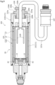
FIG. 2 is a cross-sectional view illustrating a structure of the pressure sensor of the first embodiment. -
FIG. 3 is a perspective view illustrating a structure of an inner case and a holder. For convenience of description,FIG. 3 illustrates a state in which an outer case is removed. -
FIG. 4 is a perspective view illustrating a structure of the inner case. For convenience of description,FIG. 4 illustrates a state in which the outer case is removed. -
FIG. 5 is a cross-sectional view taken along line A-A ofFIG. 2 . -
FIG. 6A is an exploded perspective view illustrating a structure of a power supply unit of the first embodiment, andFIG. 6B is a perspective view of the same. -
FIG. 7 is a perspective view illustrating a structure of a mounting member of the first embodiment. -
FIGS. 8A and 8B are perspective views illustrating a pressure sensor as an electronic device according to a second embodiment of the present invention. -
FIG. 9 is a cross-sectional view illustrating a structure of the pressure sensor of the second embodiment. -
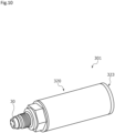
FIG. 10 is a perspective view illustrating a pressure sensor as an electronic device according to a third embodiment according to the present invention. -
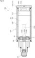
FIG. 11 is a cross-sectional view illustrating a structure of the pressure sensor of the third embodiment. -
FIG. 12A is an exploded perspective view illustrating a structure of a power supply unit of the third embodiment, andFIG. 12B is a perspective view of the same. - Modes to implementing an electronic device according to the present invention will be described on the basis of the embodiments.
- An electronic device according to a first embodiment of the present invention will be described with reference to
FIGS. 1 to 7 . In the following description, left and right sides seen from a front side ofFIG. 2 will be described as left and right sides of the electronic device. Specifically, a left side of a paper surface where asensor unit 30 is provided is described as a left side of the electronic device, and a right side of the paper surface where acap member 23 is attached is described as a right side of the electronic device. - As illustrated in
FIG. 1 , the electronic device according to the first embodiment of present invention is apressure sensor 1 that is configured to be capable of detecting pressure, which is a measurement object, and uses an external power supply (not illustrated) as a power supply. Thepressure sensor 1 is fixed to an installed portion such as a pipe, a duct, or a tank (not illustrated), and detects the pressure, which is the measurement object, inside the installed portion. The measurement object is a fluid such as a liquid or a gas. - As illustrated in
FIG. 1 , thepressure sensor 1 mainly includes ahousing 20 as an accommodation member, thesensor unit 30, a holder 100 (seeFIG. 2 ), and a circuit unit 40 (seeFIG. 2 ). Thesensor unit 30 is attached to a left end of thehousing 20. Theholder 100 is accommodated in thehousing 20 through an opening formed at a right end of the housing 20 (specifically, anopening 22a of acover member 22, which will be described later). Note that an opening of thehousing 20 is closed by thecap member 23. In addition, theholder 100 holds a mountingmember 13 to which a powersupply adjustment board 10 serving as a power supply section is fixed. That is, in the first embodiment, the power supply section includes the powersupply adjustment board 10 and the mountingmember 13. In addition, the powersupply adjustment board 10 has a converter circuit that adjusts a voltage supplied from the external power supply. - The
pressure sensor 1 is used by being fixed by, for example, screwing ascrew portion 20a in thehousing 20 into a mounting port of a pipe (not illustrated). Note that thescrew portion 20a may be formed at a left end on an outer peripheral surface of thehousing 20. In this way, a sensor element (not illustrated) provided in thesensor unit 30 outputs a voltage corresponding to pressure applied from a fluid, which is a measurement object, in the pipe. A processing chip 31 (seeFIG. 2 ) converts this voltage into a pressure signal. - As illustrated in
FIG. 2 , thehousing 20 includes anouter case 121 and an inner case 122 (seeFIGS. 3 and4 ). Theouter case 121 includes aconnection member 21, acover member 22, and thecap member 23. Thescrew portion 20a (seeFIG. 1 ) is formed at a left end of theconnection member 21. Thecover member 22 is attached to a right end of theconnection member 21. Theopening 22a on a right side of thecover member 22 is closed by thecap member 23. Theinner case 122 is fixed to theconnection member 21 and covered with thecover member 22 and thecap member 23. - As illustrated in
FIG. 2 , theconnection member 21 includes acylindrical base 21a, asmall diameter portion 21b extending leftward from thebase 21a, aflange portion 21c protruding radially outward from a right end of an outer peripheral surface of thebase 21a, and alarge diameter portion 21d extending rightward from thebase 21a. - The
small diameter portion 21b has theaforementioned screw portion 20a (seeFIG. 1 ) formed on an outer peripheral surface thereof. In addition, anannular recess 21e is formed at a right end on the outer peripheral surface of thesmall diameter portion 21b, and an O-ring 24 is attached to therecess 21e. Note that, by screwing thescrew portion 20a formed on the outer peripheral surface of thesmall diameter portion 21b into the mounting port (not illustrated) of the pipe (not illustrated), the O-ring 24 is compressed between the pipe and theconnection member 21, and sealing performance is ensured. - A
recess 21f recessed to the right is formed at a left end of thesmall diameter portion 21b, and thesensor unit 30 is inserted into therecess 21f from the left and fixed by welding. Although details are omitted, sealing performance is ensured so that the fluid, which is the measurement object, does not enter a throughhole 21m side where theprocessing chip 31 is disposed. - The
large diameter portion 21d has ascrew portion 21g (seeFIGS. 3 and4 ) formed on an outer peripheral surface thereof. In addition, anannular recess 21h is formed at a left end on the outer peripheral surface of thelarge diameter portion 21d, and an O-ring 25 is attached to therecess 21h. Note that, by screwing a screw portion (not illustrated) formed on an inner peripheral surface of the left end of thecover member 22 to thescrew portion 21g formed on the outer peripheral surface of thelarge diameter portion 21d, the O-ring 25 is compressed between theconnection member 21 and thecover member 22, and sealing performance is ensured. - A stepped
recess 21k recessed leftward is formed at a right end of thelarge diameter portion 21d, and a part of thecircuit unit 40 is accommodated in thisrecess 21k. Note that therecess 21f formed in thesmall diameter portion 21b and therecess 21k formed in thelarge diameter portion 21d communicates with each other by the throughhole 21m penetrating thebase 21a in a left-right direction. In addition, thesensor unit 30 and thecircuit unit 40 are electrically connected by a flexible printed wiring board (not illustrated) extending through the throughhole 21m. - Here, the
circuit unit 40 will be described. As illustrated inFIG. 2 , thecircuit unit 40 mainly includes a disc-shapedcircuit board 41, apositive electrode terminal 42, anegative electrode terminal 43, and a rectangular board-shaped circuit board 45 (seeFIG. 4 ) on which aprocessing chip 44 and awireless chip 46 are mounted. Thecircuit board 41 is accommodated in therecess 21k of thelarge diameter portion 21d in theconnection member 21. Thepositive electrode terminal 42 and thenegative electrode terminal 43 are arranged side by side through thecircuit board 41 in a thickness direction. Thecircuit board 45 is held on an outer surface of afirst plate 122d of theinner case 122, which will be described later. Theprocessing chip 44 adjusts power supplied from the powersupply adjustment board 10 connected to the external power supply, and processes a signal input from thesensor unit 30. Thewireless chip 46 is provided on thecircuit board 45 and communicates with the outside. Note that thecircuit board 41 and thecircuit board 45 are electrically connected by a flexibleflat cable 47. Moreover, thepositive electrode terminal 42 and thenegative electrode terminal 43 do not have to penetrate thecircuit board 41 in the thickness direction. In addition, in the first embodiment, a positive electrode terminal and a negative electrode terminal of thehousing 20, which is an accommodation member, are thepositive electrode terminal 42 and thenegative electrode terminal 43 of thecircuit unit 40. - As illustrated in
FIGS. 2 and3 , thepositive electrode terminal 42 and thenegative electrode terminal 43 are so-called probe pins, and have urging means (not illustrated). Electrical contact points of thepositive electrode terminal 42 and thenegative electrode terminal 43 are stretchable in an axial direction and urged in an extending direction. Specifically, thepositive electrode terminal 42 and thenegative electrode terminal 43 are inserted into throughholes base 122a of theinner case 122 in the thickness direction and formed side by side, and are supported so that thepositive electrode terminal 42 and thenegative electrode terminal 43 can contract leftward while the electrical contact points protrude from the throughholes FIG. 2 , while theholder 100 is attached, thepositive electrode terminal 42 and thenegative electrode terminal 43 slightly contract leftward. That is, thepositive electrode terminal 42 and thenegative electrode terminal 43 are elastically and electrically in contact with apositive electrode terminal 14 and anegative electrode terminal 15 provided on the mountingmember 13 held by theholder 100, respectively. - In this manner, the
positive electrode terminal 14 and thenegative electrode terminal 15 of the mountingmember 13 held by theholder 100 are brought into contact with thepositive electrode terminal 42 and thenegative electrode terminal 43, so that thecircuit unit 40 can supply power from the external power supply to thesensor unit 30. In addition, thecircuit unit 40 can receive input of a pressure signal from thesensor unit 30, process the signal by theprocessing chip 44, and communicate with the outside by thewireless chip 46. - As illustrated in
FIG. 2 , thecover member 22 included in theouter case 121 has a cylindrical shape, and is attached in a substantially sealed manner by a left end thereof being screwed to thescrew portion 21g (seeFIGS. 3 and4 ) formed on the outer peripheral surface of thelarge diameter portion 21d of theconnection member 21. In addition, ascrew portion 23d of thecap member 23, which is also included in theouter case 121, is screwed to a right end of thecover member 22, so that theopening 22a is closed in a substantially sealed manner. - Specifically, the
cap member 23 includes a disc-shapedbase 23a, alarge diameter portion 23b protruding leftward from a left side surface of thebase 23a, and asmall diameter portion 23c protruding leftward from an inner diameter side of a left end surface of thelarge diameter portion 23b. Thescrew portion 23d is formed on the outer peripheral surface of thesmall diameter portion 23c. In addition, anannular recess 23e is formed at the right end on the outer peripheral surface of thesmall diameter portion 23c, and an O-ring 26 is attached to thisrecess 23e. Note that, by screwing thescrew portion 23d of thecap member 23 to a screw portion (not illustrated) formed on the inner peripheral surface of the right end of thecover member 22, the O-ring 26 is compressed between thecover member 22 and thecap member 23, and sealing performance is ensured. - In addition, a through
hole 23g penetrating thebase 23a in the left-right direction is formed thereon, and a waterproof connector 27 (seeFIG. 1 ) serving as a power supply line is inserted through the throughhole 23g from the left side. Theconnector 27 is rotatable relative to thecap member 23. Further, theconnector 27 is fixed to thecap member 23 in a substantially sealed manner by screwing awaterproof nut 28 to a screw portion (not illustrated) formed on the outer peripheral surface of theconnector 27 from the right side while theconnector 27 is inserting into the throughhole 23g. In this way, internal space of thehousing 20 in which theholder 100 is accommodated is partitioned in a substantially sealed manner. - Note that the
connector 27 is electrically connected to a pair of upper andlower terminals supply adjustment board 10 byelectric wires 29 serving as power supply lines, respectively. Note that the terminal 10a of the powersupply adjustment board 10 is electrically connected to thepositive electrode terminal 14 of the mountingmember 13 through a converter circuit (not illustrated). The terminal 10b of the powersupply adjustment board 10 is electrically connected to thenegative electrode terminal 15 of the mounting member 13 (seeFIGS. 5 and7 ). That is, thepressure sensor 1 can supply power from the external power supply to thesensor unit 30 by connecting a male connector (not illustrated) connected to the external power supply to theconnector 27. - In addition, a
recess 23f recessed rightward is formed at a left end of thecap member 23, and agrip portion 100d formed at a right end of theholder 100 or a left end of theconnector 27 are accommodated in therecess 23f. - As illustrated in
FIGS. 2 to 5 , theinner case 122 is formed of a resin material, and includes thebase 122a and afirst plate 122d and asecond plate 122e extending from thebase 122a in a direction in which thecap member 23 is disposed, that is, rightward (leftward inFIG. 3 ). Thebase 122a of theinner case 122 is fixed to theconnection member 21 by a screw 123 (seeFIG. 3 ). - The through
holes base 122a as described above. Further, as illustrated inFIG. 2 , a plurality ofprojections 122f protruding leftward is formed on an outer diameter side on a left surface of thebase 122a. When theinner case 122 is fixed to theconnection member 21, theseprojections 122f sandwich an outer diameter portion of thecircuit board 41 included in thecircuit unit 40 by tips thereof in the left-right direction between stepped portions formed inside therecess 21k of theconnection member 21. In this way, thecircuit board 41 can be stably supported between theinner case 122 and the connection member 21 (seeFIG. 2 ). - In addition, a
boss 122g having a through hole into which thescrew 123 is inserted is provided on a right surface (a left surface inFIG. 3 ) of thebase 122a. - As illustrated in
FIGS. 3 and5 , thefirst plate 122d has a curved inner surface. In addition, arectangular projection 122h is formed at a left end (a right end inFIG. 3 ) on an inner surface of thefirst plate 122d. - In addition, as illustrated in
FIGS. 4 and5 , an outer surface of thefirst plate 122d forms a flat surface at a substantially vertically central portion, and a pair of upper and lower hook-shapedprotrusions 122k capable of holding thecircuit board 45 included in thecircuit unit 40 is provided at each of two locations in the horizontal direction on upper and lower ends. Note that thecircuit board 45 is inserted between the upper andlower protrusions 122k from a right side of thefirst plate 122d. Further, upper and lower side surfaces of thefirst plate 122d are curved along the inner peripheral surface of thecover member 22 included in theouter case 121. - As illustrated in
FIGS. 3 and5 , thesecond plate 122e is formed to have dimensions smaller than those of thefirst plate 122d in a vertical direction, that is, in a lateral direction. Further, on thesecond plate 122e, a pair ofridges 122m is formed to extend along the left-right direction, which is a direction in which theholder 100 is inserted and removed, that is, a longitudinal direction, on inner surface sides of upper and lower ends. Note that each of theridges 122m has a semicircular cross section. - In addition, a pair of upper and lower
semispherical projections 122n is formed at a right end (a left end inFIG. 3 ) on an inner surface of thesecond plate 122e. - In addition, the
second plate 122e has a substantiallyrectangular notch 122s formed at a substantially vertically central portion of a right end (a left end inFIG. 3 ). Note that, by forming thenotch 122s on thesecond plate 122e, a tool such as a screwdriver is prevented from interfering with thesecond plate 122e. In this way, thescrew 123 is easily locked in a through hole of theboss 122g formed on thebase 122a. - Next, the
holder 100 will be described. Note that, in the first embodiment, a description will be given of a mode in which the mountingmember 13 is held in a state in which thepositive electrode terminal 14 and thenegative electrode terminal 15 of the mountingmember 13 to which the powersupply adjustment board 10 is fixed are arranged side by side at one end of theholder 100 in the longitudinal direction. Further, in the first embodiment, theholder 100 is included in apower supply unit 101 by holding the mountingmember 13 to which the powersupply adjustment board 10 is fixed. Further, in the first embodiment, a positive electrode terminal and a negative electrode terminal of thepower supply unit 101 are thepositive electrode terminal 14 and thenegative electrode terminal 15 of the mountingmember 13. - As illustrated in
FIGS. 2 ,5 , and6A , theholder 100 mainly includes abase 100a,walls grip portion 100d. Thebase 100a has a curved inner surface. Thewall 100b is formed in a substantially triangular shape rising from a left end of thebase 100a toward an inner surface side. Thewall 100c is formed in a rectangular shape rising from a right end of thebase 100a toward the inner surface side. Thegrip portion 100d bends and extends rightward from thewall 100c. - As illustrated in
FIGS. 6A and 6B , thewall 100b has the substantially triangular shape, and abuts on one end of the mountingmember 13 in the longitudinal direction, that is, awall 13b of the mountingmember 13, which will be described later while the mountingmember 13 is held by theholder 100. In this way, thepositive electrode terminal 14 and thenegative electrode terminal 15 of the mountingmember 13 are exposed from notch-shapedspaces holder 100. Note that, as long as each of thepositive electrode terminal 42 and thenegative electrode terminal 43 can be inserted, and thepositive electrode terminal 14 and thenegative electrode terminal 15 of the mountingmember 13 can be exposed to be able to contact with thepositive electrode terminal 42 and thenegative electrode terminal 43, respectively, thewall 100b may be freely configured in shape, a through hole may be formed in the wall instead of the notch shape. - A pair of upper and
lower claws 100e is provided at each of three locations in the left-right direction at upper and lower ends of thebase 100a. In the first embodiment, the mountingmember 13 is held by the pair of upper andlower claws 100e each provided on both left and right ends. - Further, as illustrated in
FIG. 5 , an outer surface of thebase 100a forms a flat surface at a substantially vertically central portion, and aninsertion recess 100f is formed thereon. Theinsertion recess 100f opens to a left side (a right side inFIG. 3 ) where thewall 100b is formed, so that thesecond plate 122e of theinner case 122 can be inserted from the right side (the left side inFIG. 3 ). A pair of recessedgrooves 100g extending in the left-right direction, which is a direction in which theholder 100 is inserted and removed, and facing each other in the vertical direction, that is, the lateral direction, is formed on inner surface sides of upper and lower inner walls of theinsertion recess 100f. Note that the recessedgrooves 100g each have a semicircular cross section, and form a pair of guide portions G that guide movement of theholder 100 in the insertion/removal direction together with the pair ofridges 122m formed on theinner case 122 described above. - In addition, a pair of upper and lower through
holes 100h is formed at a left end (a right end inFIG. 3 ) on a bottom surface of theinsertion recess 100f. Note that the pair ofprojections 122n formed on theinner case 122 described above can be fit into the throughholes 100h, is included in a locking mechanism P that locks theholder 100 so that theholder 100 does not unintentionally move in the left-right direction, and can position theholder 100. Specifically, thewall 100b of theholder 100 abuts on a right surface of thebase 122a of theinner case 122 while theprojections 122n of theinner case 122 fit into the throughholes 100h (seeFIG. 2 ) . - As illustrated in
FIGS. 2 and6B , while the mountingmember 13 is held by theholder 100, thepositive electrode terminal 14 and thenegative electrode terminal 15 of the mountingmember 13 are arranged side by side on a left end, that is, thewall 13b. Note that a distance between thewalls holder 100 in the left-right direction is the same as or slightly shorter than the sum of dimensions of the mountingmember 13 in the left-right direction. - As illustrated in
FIGS. 2 ,6 , and7 , the mountingmember 13 is made of a resin material and mainly includes abase 13a and thewalls FIG. 7 , in the mountingmember 13, a pair of upper and lower substantially rectangular mountingportions FIG. 6 ) in thebase 13a.Elongated portions positive electrode terminal 14 and thenegative electrode terminal 15 are arranged in the mountingportions base 13a and are insert-molded. - Note that, in the first embodiment, the
positive electrode terminal 14 and thenegative electrode terminal 15 are each formed by bending a metal piece into a substantially L shape. Moreover, a pair of upper and lower hook-shapedprotrusions 13g is formed at each of two locations in the left-right direction at upper and lower ends of the mountingportions protrusions 13g abut on theelongated portions positive electrode terminal 14 and thenegative electrode terminal 15, so that insertion progress of theelongated portions positive electrode terminal 14 and thenegative electrode terminal 15 can be defined in the mountingportions - In addition, a back surface of the power
supply adjustment board 10 on a back side of the paper surface ofFIG. 2 is electrically connected to theelongated portions positive electrode terminal 14 and thenegative electrode terminal 15. In this way, thepositive electrode terminal 14 and thenegative electrode terminal 15 are electrically connected to theterminals supply adjustment board 10 through a converter circuit. - Further, in the mounting
member 13, thewall 13b is formed in a substantially elliptical shape rising from a left end of thebase 13a toward an inner surface side. A pair of upper andlower notches wall 13b in the left-right direction is formed in thewall 13b. Note that, while thepositive electrode terminal 14 and thenegative electrode terminal 15 are inserted into slits formed in horizontally central portions of thenotches elongated portions portions base 13a, respectively, and insert-molded. - Further, in the mounting
member 13, thewall 13c is formed in a substantially elliptical shape rising from the right end of thebase 13a toward the inner surface side. Anotch 13m penetrating thewall 13c in the left-right direction is formed at a substantially vertically central portion of thewall 13c. As illustrated inFIG. 2 , theelectric wires 29 for connecting theterminals supply adjustment board 10 to theconnector 27 are inserted into thenotch 13m. Note that, in the first embodiment, theelectric wires 29 are wired so as to have a sufficient bending allowance between thewall 13c and theterminals supply adjustment board 10 while being inserted into thenotch 13m of the mountingmember 13. - Next, a method of attaching and detaching the
power supply unit 101 will be described. First, when mounting thepower supply unit 101, theelectric wires 29 extending from theconnector 27 are connected to theterminals supply adjustment board 10 fixed to the mountingmember 13 held by theholder 100, respectively. - Next, the
power supply unit 101 is inserted from theopening 22a of thecover member 22 included in thehousing 20. Specifically, insertion is performed while being guided by the guide portion G (seeFIG. 5 ) including the recessedgrooves 100g formed on theholder 100 and the pair ofridges 122m formed on theinner case 122, and theprojections 122n formed on theinner case 122 are fit into the throughholes 100h formed in theholder 100, thereby locking thepower supply unit 101 in thehousing 20 by the locking mechanism P (seeFIG. 5 ). - Next, while the right end of the
connector 27 connected to thepower supply unit 101 is inserted through the throughhole 23g of thecap member 23, thescrew portion 23d of thecap member 23 is screwed to a screw portion (not illustrated) formed on the inner peripheral surface of the right end of thecover member 22. At this time, since thecap member 23 rotates relative to theconnector 27, twisting of theelectric wires 29 in thehousing 20 is prevented. - Finally, the
waterproof nut 28 is screwed from the right side to a screw portion (not illustrated) formed on the outer peripheral surface of theconnector 27 exposed to the outside through the throughhole 23g of thecap member 23. - When removing the
power supply unit 101, first, thewaterproof nut 28 that fixes theconnector 27 to thecap member 23 is turned and removed, and then thecap member 23 is turned and removed from the right end of thecover member 22. At this time, since thecap member 23 rotates relative to theconnector 27 as during mounting, twisting of theelectric wires 29 in thehousing 20 is prevented. - Next, the
power supply unit 101 is removed together with theconnector 27 and theelectric wires 29 by gripping thegrip portion 100d of theholder 100 and pulling out thepower supply unit 101. At this time, by gripping thegrip portion 100d of theholder 100, it is easy to apply force to thepower supply unit 101 in a pull-out direction. As a result, a state in which thepower supply unit 101 is locked in thehousing 20 by the locking mechanism P (seeFIG. 5 ) is easily released, so that thepower supply unit 101 can be easily removed. - In this way, by locking the
power supply unit 101 in thehousing 20 using the locking mechanism P (seeFIG. 5 ), thepressure sensor 1 can ensure a state of causing thepositive electrode terminal 42 and thenegative electrode terminal 43 of thehousing 20 to electrically contact the positive electrode terminal and the negative electrode terminal of thepower supply unit 101, that is, thepositive electrode terminal 14 and thenegative electrode terminal 15 of the mountingmember 13 held by theholder 100. In addition, while the inside of thehousing 20 in which thepower supply unit 101 is accommodated is set to a sealed space by closing the opening of thehousing 20, that is, theopening 22a of thecover member 22 using thecap member 23, the external power supply can be connected to the powersupply adjustment board 10 accommodated in thehousing 20 using theconnector 27 and theelectric wires 29 passing through thecap member 23 in a sealed state. Therefore, it is possible to achieve both stability of electrical contact between thepositive electrode terminal 42 and thenegative electrode terminal 43 of thehousing 20 and thepositive electrode terminal 14 and thenegative electrode terminal 15 of the mountingmember 13 held by theholder 100 and sealing performance inside thehousing 20. In other words, in the present embodiment, electrical connection and sealing are achieved by separate means, so that these functions can be achieved with high accuracy. - Further, by locking the
power supply unit 101 in thehousing 20 using the locking mechanism P, thepositive electrode terminal 42 and thenegative electrode terminal 43 of thehousing 20 and thepositive electrode terminal 14 and thenegative electrode terminal 15 of the mountingmember 13 held by theholder 100 are brought into elastic contact with each other, and thus electrical contact is ensured, and power can be reliably supplied. - The power
supply adjustment board 10 is detachably held by theholder 100 while being fixed to the mountingmember 13. Therefore, the powersupply adjustment board 10 can be protected by the mountingmember 13. - In addition, as illustrated in
FIG. 6A , the mountingmember 13 is attached to theholder 100 in a direction perpendicular to a direction in which theholder 100 is inserted into thehousing 20. Therefore, an operation of inserting thepower supply unit 101 into thehousing 20 has little effect on a holding state of the mountingmember 13 with respect to theholder 100, and the mountingmember 13 is stably held by theholder 100. Therefore, by locking thepower supply unit 101 in thehousing 20 using the locking mechanism P, a state in which thepositive electrode terminal 42 and thenegative electrode terminal 43 of thehousing 20 and thepositive electrode terminal 14 and thenegative electrode terminal 15 of the mountingmember 13 held by theholder 100 electrically contact each other is reliably maintained. - In addition, the
electric wires 29 included in the power supply line are flexible, and when thecap member 23 is attached or detached, by bending theelectric wires 29, it is possible to suppress occurrence of poor contact with theterminals supply adjustment board 10 or theconnector 27, and workability of attaching and detaching thecap member 23 is excellent. - In addition, when the
electric wires 29 are wired between theterminals supply adjustment board 10 and thewall 13c so as to be bendable while being inserted through thenotch 13m of the mountingmember 13, even if theelectric wires 29 are pulled in response to thecap member 23 being attached or detached or theholder 100 being inserted or removed, poor contact or short circuit is less likely to occur. - In addition, as illustrated in
FIG. 6 , thewalls holder 100 each have a piece shape which is a cantilevered plate rising from both left and right ends of thebase 100a by forming notch-shaped spaces on upper and lower sides. In this way, thewalls holder 100 can easily elastically sandwich the mountingmember 13 in the longitudinal direction. - Moreover, the
wall 100b is located between thepositive electrode terminal 14 and thenegative electrode terminal 15 of the mountingmember 13, and thus supports thepower supply unit 101 in a well-balanced manner. Furthermore, thepositive electrode terminal 14 and thenegative electrode terminal 15 of the mountingmember 13 are less likely to be shortcircuited. - In addition, since the
positive electrode terminal 14 and thenegative electrode terminal 15 of the mountingmember 13 do not protrude outward from thewall 100b, when thepower supply unit 101 is attached and detached, thepositive electrode terminal 14 and thenegative electrode terminal 15 of the mountingmember 13 are less likely to come into contact with other members. - In addition, the
holder 100 has thewall 100b that abuts on thewall 13b of the mountingmember 13, and thewall 100b is provided with notches that expose thepositive electrode terminal 14 and thenegative electrode terminal 15 of the mountingmember 13. In this way, thepositive electrode terminal 14 and thenegative electrode terminal 15 of the mountingmember 13 can be exposed from the notches provided on thewall 100b while thewall 100b abuts on thewall 13b of the mountingmember 13. That is, longitudinal positions of the positive electrode terminal and the negative electrode terminal of thepower supply unit 101 are regulated to predetermined positions. In this way, contact with thepositive electrode terminal 42 and thenegative electrode terminal 43 of thehousing 20 can be ensured. Further, thepower supply unit 101 can be made compact in the longitudinal direction. - In addition, the
holder 100 has the pair of upper andlower claws 100e sandwiching the mountingmember 13 in the lateral direction, that is, a direction in which thepositive electrode terminal 14 and thenegative electrode terminal 15 of the mountingmember 13 are arranged side by side. In this way, the mountingmember 13 can be held more stably by holding the mountingmember 13 in the lateral direction in addition to the longitudinal direction using theholder 100. In this way, contact with thepositive electrode terminal 42 and thenegative electrode terminal 43 of thehousing 20 can be made more reliably. - Moreover, since the
holder 100 can be attached and detached while thepressure sensor 1 is installed in an installed portion such as a pipe, maintenance work, etc. can be easily performed. Specifically, maintenance work can be easily performed by removing only thecap member 23 and inserting/removing only theholder 100 holding the mountingmember 13 without removing theentire housing 20 from the installed portion such as the pipe. In this way, since there is no need to touch or move thesensor unit 30 or thecircuit unit 40 during maintenance work, thepressure sensor 1 can stably sense the measurement object. Furthermore, since there is no need to remove thepressure sensor 1 from the pipe, etc., there is no need to stop an operation of a fluid system having the pipe during maintenance work. - In addition, since the
grip portion 100d is provided in theholder 100, by removing thecap member 23 and gripping thegrip portion 100d of theholder 100, thepower supply unit 101 can be easily removed from a state in which thepower supply unit 101 is locked in thehousing 20. - Note that the
outer case 121 included in thehousing 20 may be configured as a reverse screw so that thecover member 22 and theconnection member 21 do not rotate together when thecap member 23 is removed, and may be configured so that fastening force between thecap member 23 and thecover member 22 is the weakest. - Further, it is sufficient that the positive electrode terminal and the negative electrode terminal of the
power supply unit 101, that is, thepositive electrode terminal 14 and thenegative electrode terminal 15 of the mountingmember 13 held by theholder 100 are arranged vertically, and horizontal positions thereof do not have to be the same. - Moreover, the mounting
member 13, thepositive electrode terminal 14, and thenegative electrode terminal 15 are not limited to integral molding. For example, theelongated portions positive electrode terminal 14 and thenegative electrode terminal 15 may be fit and fixed to the mountingportions base 13a of the mountingmember 13. - An electronic device according to a second embodiment of the present invention will be described with reference to
FIGS. 8 and9 . Note that a description of an overlapping configuration that is the same as that of the first embodiment will be omitted. - As illustrated in
FIGS. 8 and9 , apressure sensor 201 as the electronic device of the second embodiment is different from thepressure sensor 1 of the first embodiment in that aconnector 227 serving as a power supply line is extended to the outside of acap member 223 by acable 227a collectively coveringelectric wires 229 serving as power supply lines. - Specifically, as illustrated in
FIG. 9 , in thecap member 223, a throughhole 223g penetrating abase 223a in the left-right direction is formed therein. A waterproof cable gland 228 (seeFIG. 8 ) with thecable 227a inserted therein is attached to the throughhole 223g. Thecable gland 228 includes agland body 228a, alock nut 228b and aseal nut 228c. - Here, a method of attaching the
cable gland 228 to thecap member 223 will be described. First, a left end of thegland body 228a is inserted from the right side into the throughhole 223g of thecap member 223, and thelock nut 228b is screwed from the left side to a screw portion (not illustrated) formed on an outer peripheral surface of the left end of thegland body 228a. In this way, thebase 223a of thecap member 223 is compressed between thelock nut 228b and theflange 228d formed on thegland body 228a, and thegland body 228a is attached to thecap member 223 in a substantially sealed manner. Note that, in this state, thecable 227a inserted into a throughhole 228e penetrating thegland body 228a in the left-right direction is rotatable relative to thecap member 223 and thegland body 228a. - Next, the
seal nut 228c is screwed from the right side to a screw portion (not illustrated) formed on an outer peripheral surface of a right end of thegland body 228a. Note that theseal nut 228c is previously inserted into thecable 227a before thecable 227a is inserted into the throughhole 228e of thegland body 228a. By attaching thecable gland 228 in this manner, thecable 227a is fixed to thecap member 223 in a substantially sealed manner. - In this way, while the inside of the
housing 20 in which thepower supply unit 101 is accommodated is set to a sealed space by closing the opening of thehousing 20, that is, theopening 22a of thecover member 22 using thecap member 223 to which thecable gland 228 is attached, thepressure sensor 201 can connect the external power supply to the powersupply adjustment board 10 accommodated in thehousing 20 using thecable 227a, theconnector 227, and theelectric wires 229 penetrating thecap member 223 in a sealed state. Therefore, it is possible to achieve both stability of electrical contact between thepositive electrode terminal 42 and thenegative electrode terminal 43 of thehousing 20 and thepositive electrode terminal 14 and thenegative electrode terminal 15 of the mountingmember 13 held by theholder 100 and sealing performance inside thehousing 20. - An electronic device according to a third embodiment of the present invention will be described with reference to
FIGS. 10 to 12 . Note that a description of an overlapping configuration that is the same as those of the first and second embodiments will be omitted. - A
pressure sensor 301 as the electronic device of the third embodiment is different from thepressure sensors 1 of the first and second embodiments in that the power supply section is not a power supply adjustment board and is a battery. - As illustrated in
FIGS. 10 to 12 , thepressure sensor 301 of the third embodiment mainly includes ahousing 320 different from that of the first and second embodiments in acap member 323, and thesensor unit 30, theholder 100, and the circuit unit 40 (seeFIG. 2 ), which are the same as those of the first and second embodiments. - Unlike the first and second embodiments, the
cap member 323 in the third embodiment does not have a through hole in abase 323a. - Note that, in the third embodiment, a description will be given of a mode of holding a pack-type lithium battery 310 (hereinafter simply referred to as "
battery 310") in which apositive electrode 310a and anegative electrode 310b are arranged side by side at one end in the longitudinal direction of theholder 100 and aspacer 313 formed of a resin material. Further, in the third embodiment, theholder 100 is included in thepower supply unit 101 by holding thebattery 310 and thespacer 313. Further, in the third embodiment, the positive electrode terminal and the negative electrode terminal of thepower supply unit 101 are thepositive electrode 310a and thenegative electrode 310b of thebattery 310. - In addition, the
first plate 122d in theinner case 122 has an inner surface curved along a surface shape of thebattery 310 held by the holder 100 (seeFIG. 3 ). In addition, therectangular projection 122h formed at the left end (right end inFIG. 3 ) of the inner surface of thefirst plate 122d can be fit into arecess 310c (seeFIGS. 11 and12 ) formed on a surface of thebattery 310. In this way, the insertion/removal direction of theholder 100 with respect to theinner case 122 is regulated, and reverse connection of thebattery 310 can be prevented. - As illustrated in
FIGS. 11 andFIG. 12B , while thebattery 310 and thespacer 313 are held in theholder 100, thebattery 310 has thepositive electrode 310a and thenegative electrode 310b arranged side by side at a left end, that is, one end in the longitudinal direction. In addition, thespacer 313 abuts on a right end of thebattery 310, that is, the other end in the longitudinal direction and thewall 100c of theholder 100. Note that a distance between thewalls holder 100 in the left-right direction is the same as or slightly shorter than the sum of dimensions of thebattery 310 in the left-right direction and dimensions of thespacer 313 in the left-right direction. - In this way, by locking the
power supply unit 101 in thehousing 20 using the locking mechanism P (seeFIG. 5 ), thepressure sensor 301 can ensure a state in which the positive electrode terminal and the negative electrode terminal of thepower supply unit 101, that is, thepositive electrode 310a and thenegative electrode 310b of thebattery 310 held by theholder 100 are in electrical contact with thepositive electrode terminal 42 and thenegative electrode terminal 43 of thehousing 320. Further, by covering the opening of thehousing 320 with thecap member 323, the inside of thehousing 320 in which thepower supply unit 101 is accommodated can be set to a sealed space. Therefore, it is possible to achieve both stability of electrical contact between thepositive electrode terminal 42 and thenegative electrode terminal 43 of thehousing 320 and thepositive electrode 310a and thenegative electrode 310b of thebattery 310 held by theholder 100 and sealing performance inside thehousing 320. - Further, in the third embodiment, the
positive electrode 310a and thenegative electrode 310b of thebattery 310 held by theholder 100 can be used as the positive electrode terminal and the negative electrode terminal of thepower supply unit 101 without change, and thus a structure of thespacer 313 can be simplified. - Further, in the third embodiment, the power supply section includes the battery and the spacer corresponding to the shape of the battery, and thus can hold the battery and the spacer having different shapes by the
common holder 100 using the spacer corresponding to the shape of the battery used in thepower supply unit 101. For example, thepower supply unit 101 may be configured by holding a battery other than the above-mentioned pack-type lithium battery, for example, a button-type battery, an AA battery, an AAA battery, a square battery, or a coin-type battery, and a spacer corresponding to shapes of these batteries using thecommon holder 100. - Furthermore, in the present invention, the
common holder 100 can be used to hold the mountingmember 13 to which the powersupply adjustment board 10 is fixed as in the first and second embodiments, or thebattery 310 andspacer 313 as in the third embodiment. Therefore, the pressure sensor can selectively use the external power supply or the battery as a power supply according to an installation location, a usage environment, etc. by using a cap member according to the power supply section to be used. - Even though the embodiments of the present invention have been described above with reference to the drawings, the specific configuration is not limited to these embodiments, and any changes or additions within the scope not departing from the scope of the present invention are included in the present invention.
- For example, the electronic device of the present invention is not limited to the pressure sensor, and may be applied to other sensors or electronic devices other than sensors as long as the electronic device uses a battery as a power supply.
- In addition, a control chip or the wireless chip included in the circuit unit may be provided at any position on the circuit board.
- Further, in the above-described embodiments, a description has been given of a mode in which the positive electrode terminal and the negative electrode terminal of the accommodation member are configured to be stretchable. However, the present invention is not limited thereto, and the positive electrode terminal and the negative electrode terminal of the power supply unit may be configured to be stretchable. Both the positive electrode terminal and negative electrode terminal of the accommodation member and the positive electrode terminal and negative electrode terminal of the power supply unit may be configured to be stretchable. For example, electrical contact points of the positive electrode terminal and the negative electrode terminal may protrude from notches provided on the
wall 100b of theholder 100, respectively, by applying a configuration of a probe pin or a spring terminal to thepositive electrode terminal 14 and thenegative electrode terminal 15 of the mountingmember 13 in the first and second embodiments. - Moreover, in the first and second embodiments, a description has been given of a mode in which the waterproof nut or the cable gland is used to allow the power supply line, to which the external power supply can be connected, to pass through the through hole of the cap member in a sealed state. However, the present invention is not limited thereto. For example, a gasket, etc. may be used to ensure sealing performance between the power supply line and the cap member.
- Further, the mounting member to which the power supply adjustment board is fixed is not limited to being attachable and detachable with respect to the holder, and the mounting member and the holder may be integrally formed.
- In addition, the power supply adjustment board may be directly held by the holder without the mounting member interposed therebetween. In this case, for example, the positive electrode terminal and the negative electrode terminal of the power supply unit electrically connected to the terminals of the power supply adjustment board may be vertically arranged side by side at one end of the power supply adjustment board in the longitudinal direction.
- In addition, the locking mechanism P is not limited to being configured by fitting the projection of the inner case into the through hole of the holder, and may be configured by concave-convex fitting using a recess formed on the holder and a projection formed on the inner case. In addition, the locking mechanism may be configured by concave-convex fitting using a projection formed on the holder and a through hole or a recess formed on the inner case.
-
- 1
- Pressure sensor (electronic device)
- 10
- Power supply adjustment board (power supply section)
- 10a,
- 10b Terminal
- 13
- Mounting member
- 14
- Positive electrode terminal (positive electrode terminal of power supply unit)
- 15
- Negative electrode terminal (negative electrode terminal of power supply unit)
- 20
- Housing (accommodation member)
- 21
- Connection member
- 22
- Cover member
- 22a
- Opening (opening of accommodation member)
- 23
- Cap member
- 23g
- Through hole
- 27
- Connector (power supply line)
- 28
- Waterproof nut
- 29
- Electric wire (power supply line)
- 30
- Sensor unit
- 40
- Circuit unit
- 41
- Circuit board
- 42
- Positive electrode terminal (positive electrode terminal of accommodation member)
- 43
- Negative electrode terminal (negative electrode terminal of accommodation member)
- 44
- Processing chip
- 45
- Circuit board
- 46
- Wireless chip
- 100
- Holder
- 100b,
- 100c Wall
- 100d
- Grip portion
- 101
- Power supply unit
- 201
- Pressure sensor (electronic device)
- 223
- Cap member
- 223g
- Through hole
- 227
- Connector (power supply line)
- 227a
- Cable (power supply line)
- 228
- Cable gland
- 228a
- Gland body
- 228b
- Lock nut
- 228c
- Seal nut
- 229
- Electric wire (power supply line)
- 301
- Pressure sensor (electronic device)
- 310
- Battery (power supply section)
- 310a
- Positive electrode (positive electrode terminal of power supply unit)
- 310b
- Negative electrode (negative electrode terminal of power supply unit)
- 313
- Spacer (power supply section)
- 323
- Cap member
- G
- Guide portion
- P
- Locking mechanism
Claims (7)
- An electronic device, comprising:a power supply unit including a power supply adjustment board and a holder that holds the power supply adjustment board;an accommodation member that accommodates the power supply unit inserted from an opening of the accommodation member; anda cap member that closes the opening of the accommodation member, whereina positive electrode terminal and a negative electrode terminal are arranged side by side in the accommodation member,a positive electrode terminal and a negative electrode terminal are arranged side by side on one end side in the power supply unit,the electronic device further comprises: a locking mechanism that locks the power supply unit in the accommodation member while the positive electrode terminal and the negative electrode terminal of the power supply unit are brought into electrical contact with the positive electrode terminal and the negative electrode terminal of the accommodation member; anda power supply line disposed to penetrate the cap member in a sealed state and configured for connecting an external power supply to the power supply adjustment board.
- The electronic device according to claim 1, wherein the power supply adjustment board is detachably held by the holder while being fixed to a mounting member on which the positive electrode terminal and the negative electrode terminal of the power supply unit are provided.
- The electronic device according to claim 2, wherein the mounting member is attached to the holder in a direction perpendicular to a direction in which the holder is inserted into the accommodation member.
- The electronic device according to any one of claims 1 to 3, wherein at least a part of the power supply line is flexible.
- The electronic device according to any one of claims 1 to 3, wherein the holder has a grip portion.
- An electronic device, comprising:a power supply unit including a holder and a power supply section held by the holder;an accommodation member that accommodates the power supply unit inserted from an opening of the accommodation member; anda cap member that closes the opening of the accommodation member, whereina positive electrode terminal and a negative electrode terminal are arranged side by side in the accommodation member,a positive electrode terminal and a negative electrode terminal are arranged side by side on one end side in the power supply unit,the electronic device further comprises a locking mechanism that locks the power supply unit in the accommodation member while the positive electrode terminal and the negative electrode terminal of the power supply unit are brought into electrical contact with the positive electrode terminal and the negative electrode terminal of the accommodation member, andthe power supply section has a power supply adjustment board to which a battery or an external power supply is connected.
- The electronic device according to claim 6, wherein the power supply section includes the battery and a spacer corresponding to a shape of the battery.
Applications Claiming Priority (2)
| Application Number | Priority Date | Filing Date | Title |
|---|---|---|---|
| JP2021135835A JP7772527B2 (en) | 2021-08-23 | 2021-08-23 | electronic equipment |
| PCT/JP2022/031492 WO2023027001A1 (en) | 2021-08-23 | 2022-08-22 | Electronic device |
Publications (2)
| Publication Number | Publication Date |
|---|---|
| EP4395479A1 true EP4395479A1 (en) | 2024-07-03 |
| EP4395479A4 EP4395479A4 (en) | 2026-04-22 |
Family
ID=85322138
Family Applications (1)
| Application Number | Title | Priority Date | Filing Date |
|---|---|---|---|
| EP22861289.1A Pending EP4395479A4 (en) | 2021-08-23 | 2022-08-22 | ELECTRONIC DEVICE |
Country Status (5)
| Country | Link |
|---|---|
| US (1) | US20240356177A1 (en) |
| EP (1) | EP4395479A4 (en) |
| JP (1) | JP7772527B2 (en) |
| CN (1) | CN117813920A (en) |
| WO (1) | WO2023027001A1 (en) |
Family Cites Families (11)
| Publication number | Priority date | Publication date | Assignee | Title |
|---|---|---|---|---|
| JPS6291664U (en) | 1985-11-29 | 1987-06-11 | ||
| JPS6339862U (en) * | 1986-09-01 | 1988-03-15 | ||
| JPH051039Y2 (en) | 1987-06-15 | 1993-01-12 | ||
| JPH0716363U (en) * | 1993-08-27 | 1995-03-17 | 松下電器産業株式会社 | Dry battery adapter |
| JP3179948B2 (en) * | 1993-10-06 | 2001-06-25 | 株式会社リコー | Electronics |
| JP2004165251A (en) | 2002-11-11 | 2004-06-10 | Sharp Corp | Heat dissipation device for electronic components |
| JP2006280186A (en) | 2005-03-30 | 2006-10-12 | Kyocera Corp | adapter |
| JP2010147094A (en) | 2008-12-16 | 2010-07-01 | Sony Corp | Case body |
| JP6961985B2 (en) | 2017-02-10 | 2021-11-05 | ソニーグループ株式会社 | Battery and connected devices |
| EP3760385B1 (en) * | 2019-07-01 | 2024-03-20 | Guido Valentini | Electric power tool with two or more battery units and electric power tool arrangement comprising such an electronic power tool and a voltage converter unit |
| CN211606978U (en) | 2020-04-10 | 2020-09-29 | 东莞迈新光电有限公司 | LED driving power supply convenient to disassemble and maintain |
-
2021
- 2021-08-23 JP JP2021135835A patent/JP7772527B2/en active Active
-
2022
- 2022-08-22 WO PCT/JP2022/031492 patent/WO2023027001A1/en not_active Ceased
- 2022-08-22 CN CN202280056177.6A patent/CN117813920A/en active Pending
- 2022-08-22 EP EP22861289.1A patent/EP4395479A4/en active Pending
- 2022-08-22 US US18/684,599 patent/US20240356177A1/en active Pending
Also Published As
| Publication number | Publication date |
|---|---|
| JP2023030611A (en) | 2023-03-08 |
| WO2023027001A1 (en) | 2023-03-02 |
| CN117813920A (en) | 2024-04-02 |
| US20240356177A1 (en) | 2024-10-24 |
| JP7772527B2 (en) | 2025-11-18 |
| EP4395479A4 (en) | 2026-04-22 |
Similar Documents
| Publication | Publication Date | Title |
|---|---|---|
| US8497435B2 (en) | Cable mounting structure for electric apparatus | |
| JP5356038B2 (en) | Industrial process field device with battery assembly of limited energy | |
| JP4753817B2 (en) | Charger | |
| EP2423028B1 (en) | Power supply control device | |
| US20040166744A1 (en) | Junction terminal and connector having the same | |
| JP5939954B2 (en) | Terminal spacer | |
| JP6293820B2 (en) | Charging connector | |
| ES3059565T3 (en) | Connector and electric device | |
| KR20230133034A (en) | Terminal temperature sensing connector | |
| US20240356177A1 (en) | Electronic device | |
| US11954948B1 (en) | Vehicle communication interface cable with integrated battery | |
| CN209526284U (en) | Connector, to mating connector and connector assembly | |
| EP4207453A1 (en) | Electronic instrument | |
| JP2020004630A (en) | Charging connector | |
| US20230291058A1 (en) | Electronic device and battery holder | |
| JP2014102920A (en) | Hand-held electronic device, battery with connector, battery lid, connector and connector anti-separation method | |
| EP4195386A1 (en) | Electronic device | |
| CN223006226U (en) | Smart electric meter control system and ammeter casing | |
| US12633609B2 (en) | Electronic device | |
| KR200445799Y1 (en) | Connector | |
| CN222868114U (en) | Electric connector, electric connector assembly, electric equipment and vehicle | |
| CN118696470A (en) | Battery plug-in connection device including embedded socket and embedded plug | |
| CN219040791U (en) | Binding post and power | |
| US20110315244A1 (en) | Gas distribution unit | |
| JP4008345B2 (en) | connector |
Legal Events
| Date | Code | Title | Description |
|---|---|---|---|
| STAA | Information on the status of an ep patent application or granted ep patent |
Free format text: STATUS: THE INTERNATIONAL PUBLICATION HAS BEEN MADE |
|
| PUAI | Public reference made under article 153(3) epc to a published international application that has entered the european phase |
Free format text: ORIGINAL CODE: 0009012 |
|
| STAA | Information on the status of an ep patent application or granted ep patent |
Free format text: STATUS: REQUEST FOR EXAMINATION WAS MADE |
|
| 17P | Request for examination filed |
Effective date: 20240220 |
|
| AK | Designated contracting states |
Kind code of ref document: A1 Designated state(s): AL AT BE BG CH CY CZ DE DK EE ES FI FR GB GR HR HU IE IS IT LI LT LU LV MC MK MT NL NO PL PT RO RS SE SI SK SM TR |
|
| DAV | Request for validation of the european patent (deleted) | ||
| DAX | Request for extension of the european patent (deleted) | ||
| REG | Reference to a national code |
Ref country code: DE Ref legal event code: R079 Free format text: PREVIOUS MAIN CLASS: H05K0005020000 Ipc: H01M0050247000 |
|
| A4 | Supplementary search report drawn up and despatched |
Effective date: 20260320 |
|
| RIC1 | Information provided on ipc code assigned before grant |
Ipc: H01M 50/247 20210101AFI20260316BHEP Ipc: H01M 50/289 20210101ALI20260316BHEP Ipc: H01M 50/296 20210101ALI20260316BHEP Ipc: H01M 50/55 20210101ALN20260316BHEP |