EP4395458A1 - An induction heating cooker - Google Patents
An induction heating cooker Download PDFInfo
- Publication number
- EP4395458A1 EP4395458A1 EP23212974.2A EP23212974A EP4395458A1 EP 4395458 A1 EP4395458 A1 EP 4395458A1 EP 23212974 A EP23212974 A EP 23212974A EP 4395458 A1 EP4395458 A1 EP 4395458A1
- Authority
- EP
- European Patent Office
- Prior art keywords
- plate
- induction heating
- holder
- cooking
- cooker
- Prior art date
- Legal status (The legal status is an assumption and is not a legal conclusion. Google has not performed a legal analysis and makes no representation as to the accuracy of the status listed.)
- Granted
Links
Images

Classifications
-
- H—ELECTRICITY
- H05—ELECTRIC TECHNIQUES NOT OTHERWISE PROVIDED FOR
- H05B—ELECTRIC HEATING; ELECTRIC LIGHT SOURCES NOT OTHERWISE PROVIDED FOR; CIRCUIT ARRANGEMENTS FOR ELECTRIC LIGHT SOURCES, IN GENERAL
- H05B6/00—Heating by electric, magnetic or electromagnetic fields
- H05B6/02—Induction heating
- H05B6/10—Induction heating apparatus, other than furnaces, for specific applications
- H05B6/12—Cooking devices
- H05B6/1209—Cooking devices induction cooking plates or the like and devices to be used in combination with them
- H05B6/1245—Cooking devices induction cooking plates or the like and devices to be used in combination with them with special coil arrangements
- H05B6/1272—Cooking devices induction cooking plates or the like and devices to be used in combination with them with special coil arrangements with more than one coil or coil segment per heating zone
-
- H—ELECTRICITY
- H05—ELECTRIC TECHNIQUES NOT OTHERWISE PROVIDED FOR
- H05B—ELECTRIC HEATING; ELECTRIC LIGHT SOURCES NOT OTHERWISE PROVIDED FOR; CIRCUIT ARRANGEMENTS FOR ELECTRIC LIGHT SOURCES, IN GENERAL
- H05B2206/00—Aspects relating to heating by electric, magnetic, or electromagnetic fields covered by group H05B6/00
- H05B2206/02—Induction heating
- H05B2206/022—Special supports for the induction coils
-
- H—ELECTRICITY
- H05—ELECTRIC TECHNIQUES NOT OTHERWISE PROVIDED FOR
- H05B—ELECTRIC HEATING; ELECTRIC LIGHT SOURCES NOT OTHERWISE PROVIDED FOR; CIRCUIT ARRANGEMENTS FOR ELECTRIC LIGHT SOURCES, IN GENERAL
- H05B2213/00—Aspects relating both to resistive heating and to induction heating, covered by H05B3/00 and H05B6/00
- H05B2213/07—Heating plates with temperature control means
Definitions
- the induction heating cooker realized in order to attain the aim of the present invention, explicated in the first claim and the respective claims thereof, comprises a cooker glass whereon the cooking vessel is placed; at least one coil which is positioned under the cooker glass and which provides the heating of the cooking vessel; a plate which is positioned under the at least one coil; and a monolithic holder which is connected to at least one connection edge of the plate by means of a connection member from at least one holder arm so as to be flush with the plate and whereon at least one infrared sensor detecting the infrared rays emitted from the cooking vessel thereabove and at least one temperature sensor detecting the temperature of the cooker glass whereon the cooking vessel is positioned can be positioned at a certain distance from each other and kept together.
- the induction heating cooker of the present invention comprises a holder comprising a connection member having a claw-shaped structure so as to be attached to a connection edge of the plate.
- the present invention relates to an induction heating cooker (1) having an infrared sensor (6) which detects infrared rays emitted from a heated cooking vessel and a temperature sensor (7) which detects the temperature of the cooker glass (2) whereon the cooking vessel is positioned.
Landscapes
- Physics & Mathematics (AREA)
- Electromagnetism (AREA)
- Induction Heating Cooking Devices (AREA)
- Electric Stoves And Ranges (AREA)
Abstract
Description
- The present invention relates to a sensor design which enables contactless measurement of the temperature of the cooking vessel in the induction heating cookers.
- With the developments in technology and new usage habits, the users need cooking support to keep the temperature of the foodstuffs in the cooking vessel (pot, pan, etc.) under control throughout the cooking process. In line with said need of the users, if the temperature of the pot or pan can be measured during the cooking process, the cooking process can be performed at the targeted ideal temperatures. By measuring the temperature of the cooking vessel or the foodstuffs therein, the foodstuffs can be cooked in a healthy manner while ensuring the best cooking performance and the automatic cooking. Thus, significant improvements in the cooking quality, health and user comfort are provided. Moreover, energy efficiency increases and security risks are minimized.
- In traditional state of the art induction heating cookers, a power level is generally selected from a range of 1 to 10. However, as a result of this selection, the induction heating cooker keeps the power at the selected level but cannot provide temperature control. Therefore, the temperature changes uncontrollably during the cooking process, and this change causes the foodstuffs to burn or be overcooked or not to be cooked as desired.
- Adjusting the temperature while cooking on the induction heating cooker creates some difficulties and problems in the state of the art. Various technical problems arise depending on the temperature measurement method to be used.
- To ensure the optimum cooking vessel temperature control, it is required to use a sensor and a control and measurement algorithm working depending on the same. At this point, different measurement methods are used depending on the location of the sensor. Said methods include placing an apparatus in the cooking vessel, attaching an apparatus on the pot, and placing a detection system on and in the cooker. All these methods basically include a sensor technology.
- However, measurement by placing an apparatus in the cooking vessel or attaching an apparatus to the outer surface thereof, which are among the state of the art techniques, often causes difficulty in use and a safety hazard. In the method of measuring through a detection on the cooker, losses in measurement sensitivity and application difficulties occur due to dirt accumulation.
- Another problem encountered in the state of the art is that when the heating process starts in the induction heating cooker, the cooking vessel heats up first and then the foodstuffs heat up. Meanwhile, the cooker glass also begins to heat up due to indirect heat transfer. Therefore, the sensor cannot directly and exclusively measure the temperature of the cooking vessel. This creates a problem in reaching the required temperature for the foodstuffs in the cooking vessel to be cooked in the most efficient way.
- In the state of the art Patent No.
EP1562405B1 , an induction heating cooker is disclosed, comprising an infrared sensor for sensing an infrared intensity from a load pot, a waveguide for guiding infrared radiation from the load pot to the infrared sensor, a first magnetism-proofing unit and a second magnetism-proofing unit for reducing magnetic fluxes. - Given the problems in the state of the art, there is a need for an induction heating cooker which ensures that the temperature of the cooking vessel can be measured and controlled, which enables the temperature of the cooking vessel to be set and kept at a certain temperature and which prevents the foodstuffs being cooked from burning or from being left uncooked.
- The aim of the present invention is to provide cooking support to keep the temperature of the foodstuffs in the cooking vessel under control by enabling the temperature of the cooking vessel to be measured accurately.
- The aim of the present invention is to eliminate the misleading information coming from the heated glass while measuring the temperature of the cooking vessel (pot, pan, etc.) by the infrared sensor positioned in an induction heating cooker.
- Another aim of the present invention is to minimize the distance between the glass and the sensors used so as to prevent radiation from the environment and to perform more focused measurements.
- Another aim of the present invention is to provide thermal insulation and prevent the sensor system from being affected by high temperatures on the coil plate.
- Another aim of the present invention is to eliminate electrical noise caused by the electromagnetic field generated during heating, which affects the measurements of the sensor system.
- Another aim of the present invention is to ensure that the temperature of the cooking vessel can be measured and controlled such that the temperature of the cooking vessel can be set and kept at a certain temperature and the foodstuffs being cooked are prevented from burning or from being left uncooked.
- Another aim of the present invention is to prevent unnecessary operation and provide energy efficiency by making temperature control possible.
- The induction heating cooker realized in order to attain the aim of the present invention, explicated in the first claim and the respective claims thereof, comprises a cooker glass whereon the cooking vessel is placed; at least one coil which is positioned under the cooker glass and which provides the heating of the cooking vessel; a plate which is positioned under the at least one coil; and a monolithic holder which is connected to at least one connection edge of the plate by means of a connection member from at least one holder arm so as to be flush with the plate and whereon at least one infrared sensor detecting the infrared rays emitted from the cooking vessel thereabove and at least one temperature sensor detecting the temperature of the cooker glass whereon the cooking vessel is positioned can be positioned at a certain distance from each other and kept together.
- The induction heating cooker of the present invention comprises a U-shaped monolithic holder comprising the first arm which is joined with the first connection edge of the plate, a second arm which is joined with the second connection edge of the plate, at least two connection members, at least one on each arm so as to ensure the connection between the holder and the plate, and a recessed base surface whereon at least one infrared sensor and at least one temperature sensor are positioned.
- The induction heating cooker of the present invention comprises at least one cooking zone comprising at least two quadrangular coils providing the heating of the cooking vessel, and the plate positioned under the coils forming said cooking zone.
- The induction heating cooker of the present invention comprises at least one infrared sensor and at least one temperature sensor which are placed on the base surface of the holder so as to be positioned between the two quadrangular coils.
- The induction heating cooker of the present invention comprises at least one cooking zone comprising a circular coil providing the heating of the cooking vessel, and the plate positioned under the coil forming said cooking zone.
- The induction heating cooker of the present invention comprises at least one infrared sensor and at least one temperature sensor which are placed on the base surface of the holder so as to be aligned with the center of the circular coil.
- The induction heating cooker of the present invention comprises the desired number of cooking zones comprising the desired number of quadrangular coils and the desired number of cooking zones comprising a circular coil, and the plate placed under the coil or coils in each cooking zone.
- The induction heating cooker of the present invention comprises a holder which is manufactured from plastic, ceramic or metal material.
- The induction heating cooker of the present invention comprises a holder comprising a connection member having a claw-shaped structure so as to be attached to a connection edge of the plate.
- An induction heating cooker realized in order to attain the aim of the present invention is illustrated in the attached figures, where:
-
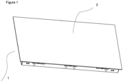
Figure 1 : is the top perspective view of an induction heating cooker. -
Figure 2 : is the front perspective view of the holder enabling the sensor system in an induction heating cooker to be positioned together. -
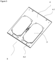
Figure 3 : is the top perspective view of a cooking zone. - The following numerals are referred to in the description of the present invention:
- 1. Induction cooker
- 2. Cooker glass
- 3. Coil
- 4. Plate
- 4.1 First connection edge
- 4.2 Second connection edge
- 5. Cooking zone
- 6. Infrared temperature sensor
- 7. Temperature sensor
- 8. Holder
- 8.1 First arm
- 8.2 Second arm
- 8.3 Connection member
- 8.4 Base surface
- The present invention relates to an induction heating cooker (1) having an infrared sensor (6) which detects infrared rays emitted from a heated cooking vessel and a temperature sensor (7) which detects the temperature of the cooker glass (2) whereon the cooking vessel is positioned.
- In an embodiment of the present invention, the induction heating cooker (1) comprises a cooker glass (2) whereon the cooking vessel is placed; at least one coil (3) which is positioned under the cooker glass (2) and which provides the heating of the cooking vessel; a plate (4) which is positioned under the at least one coil (3); and a monolithic holder (8) which is connected to at least one connection edge (4.1, 4.2) of the plate (4) by means of a connection member (8.3) from at least one holder arm (8.1, 8.2) so as to be flush with the plate (4) and whereon at least one infrared sensor (6) detecting the infrared rays emitted from the cooking vessel thereabove and at least one temperature sensor (7) detecting the temperature of the cooker glass (2) whereon the cooking vessel is positioned can be positioned at a certain distance from each other and kept together.
- In an embodiment of the present invention, the plate (4) is manufactured from metal material.
- In an embodiment of the present invention, the U-shaped monolithic holder (8) comprises the first arm (8.1) which is joined with the first connection edge (4.1) of the plate (4), a second arm (8.2) which is joined with the second connection edge (4.2) of the plate (4), and a recessed base surface (8.4) whereon at least one infrared sensor (6) and at least one temperature sensor (7) are positioned. Thus, an air gap is formed between the sensor system (6, 7) and the plate (4). In said embodiment, the infrared sensor (6) and the temperature sensor (7) are positioned at a certain distance from each other on the base surface (8.4) of the holder (8). In order to ensure the connection with the plate (4), the holder (8) comprises at least two connection members (8.3), at least one on each arm (8.1, 8.2), which join a first arm (8.1) with the first connection edge (4.1) and a second arm (8.2) with the second connection edge (4.2). In the induction heating cookers (1), low or high temperatures cannot be measured with the same sensor. A separate sensor should be used for each measurement. Therefore, by means of said holder (8), a plurality of sensors can be positioned on the holder (8) so as not to directly contact the cooker glass (2) but so as to be as close as possible to the cooker glass (2), and by means of the assembly of the holder (8) and the plate (4), accurate measurements can be made in the induction heating cookers (1).
- In an embodiment of the present invention, the connection member (8.3) is in the form of a claw. Said claw form is engaged with the first connection edge (4.1) and the second connection edge (4.2) of the plate (4) to ensure the connection between the holder (8) and the plate (4). In another embodiment of the present invention, the connection member (8.3) is a screw housing. The first connection edge (4.1) and the second connection edge (4.2) of the plate (4) are screwed to said screw housing to ensure the connection between the holder (8) and the plate (4). In another embodiment of the present invention, the connection member (8.3), the first connection edge (4.1) and the second connection edge (4.2) are mounted together with a sliding and interlocking structure.
- The infrared sensor (6) and the temperature sensor (7) have a viewing angle, and it is critical to measure the temperature of the cooker glass (2) area within this viewing angle from the closest possible point to make an accurate compensation. By means of the mounting of the holder (8) and the plate (4) to each other with said different mounting methods and the positioning of the infrared sensor (6) and the temperature sensor (7) on the holder (8), the sensor system composed of at least one infrared sensor (6) and at least one temperature sensor (7) measures the temperature of the cooker glass (2) from the closest possible distance so as to ensure that the most accurate values are obtained. Thus, a sensor system which is not affected by misleading radiation coming from the cooker glass (2) and other reflections on the induction heating cooker (1) and which makes an accurate measurement becomes possible.
- In an embodiment of the present invention, the induction heating cooker (1) comprises at least two quadrangular coils (3) which provide the heating of the cooking vessel. A cooking zone (5) is formed by bringing together the desired number of coils (3). The plate (4) is positioned under the coils (3) forming said cooking zone (5). The infrared sensor (6) and the temperature sensor (7) are placed on the base surface (8.4) of the holder (8) so as to be positioned between said two quadrangular coils (3) and the holder (8) is connected to the plate (4). While in operation operating, the induction heating cooker (1) creates an electromagnetic field according to the design of the coils (3) in order to provide heating. The waves emitted from said electromagnetic field transform into heat energy on the cooking vessel and provide heating. By means of the arrangement of the coils (3) and the sensors (6, 7) described in the present invention, electrical noise is prevented and the sensors (6, 7) are enabled to operate smoothly.
- In another embodiment of the present invention, the induction heating cooker (1) comprises at least one circular coil (3) which provides the heating of the cooking vessel. The region where the circular coil (3) is located is accepted as a cooking zone (5). Said induction heating cooker (1) comprises at least one cooking zone (5) and the plate (4) is positioned under the circular coil (3) in each cooking zone (5). The infrared sensor (6) and the temperature sensor (7) are placed on the base surface (8.4) of the holder (8) so as to be aligned with the center of the circular coil (3) and the holder (8) is connected to the plate (4).
- In another embodiment of the present invention, the cooking zones (5) are formed on the induction heating cooker (1) with the desired number of quadrangular and circular coils (3). The plate (4) is placed under the coil or coils (3) located in each cooking zone (5). Depending on the form of the coil (3) used, the infrared sensor (6) and the temperature sensor (7) are placed on the base surface (8.4) of the holder (8) between the two quadrangular coils (3) or in the center of the circular coil (3), and the holder (8) is connected to the plate (4).
- In an embodiment of the present invention, the holder (8) is manufactured from plastic, metal or ceramic material. Thus, the heat transfer from the plate (4), which reaches high temperatures, to the sensors (6, 7) is prevented and the sensors (6, 7) are enabled to operate smoothly and take accurate measurements. In an embodiment of the present invention, if the holder (8) is manufactured from metal or ceramic material, it is possible to cool the holder (8) faster.
Claims (9)
- An induction heating cooker (1) comprising a cooker glass (2) whereon the cooking vessel is placed; at least one coil (3) positioned under the cooker glass (2) and providing the heating of the cooking vessel; and a plate (4) positioned under the at least one coil (3); characterized by a holder (8) connected to at least one connection edge (4.1, 4.2) of the plate (4) by means of a connection member (8.3) from at least one holder arm (8.1, 8.2) so as to be flush with the plate (4) and whereon at least one infrared sensor (6) detecting the infrared rays emitted from the cooking vessel there above and at least one temperature sensor (7) detecting the temperature of the cooker glass (2) whereon the cooking vessel is positioned at a certain distance from each other and kept together.
- An induction heating cooker (1) as in Claim 1, characterized by a U-shaped monolithic holder (8) comprising the first arm (8.1) joined with the first connection edge (4.1) of the plate (4), a second arm (8.2) joined with the second connection edge (4.2) of the plate (4), at least two connection members (8.3), at least one on each arm (8.1, 8.2) so as to ensure the connection between the holder (8) and the plate (4), and a recessed base surface (8.4) whereon at least one infrared sensor (6) and at least one temperature sensor (7) are positioned.
- An induction heating cooker (1) as in Claim 1 or 2, characterized by at least one cooking zone (5) comprising at least two quadrangular coils (3) providing the heating of the cooking vessel, and the plate (4) positioned under the coils (3) forming said cooking zone (5).
- An induction heating cooker (1) as in Claim 3, characterized by at least one infrared sensor (6) and at least one temperature sensor (7) which are placed on the base surface (8.4) of the holder (8) so as to be positioned between the two quadrangular coils (3).
- An induction heating cooker (1) as in Claim 1 or 2, characterized by at least one cooking zone (5) comprising a circular coil (3) providing the heating of the cooking vessel, and the plate (4) positioned under the coil (3) forming said cooking zone (5).
- An induction heating cooker (1) as in Claim 5, characterized by at least one infrared sensor (6) and at least one temperature sensor (7) which are placed on the base surface (8.4) of the holder (8) so as to be aligned with the center of the circular coil (3).
- An induction heating cooker (1) as in any one of Claims 4 to 6, characterized by the desired number of cooking zones (5) comprising the desired number of quadrangular coils (3) and the desired number of cooking zones (5) comprising a circular coil (3), and the plate (4) placed under the coil or coils (3) in each cooking zone (5).
- An induction heating cooker (1) as in any one of the above claims, characterized by a holder (8) which is manufactured from plastic, ceramic or metal material.
- An induction heating cooker (1) as in any one of the above claims, characterized by the holder (8) comprising the claw-shaped connection member (8.3) which can be engaged with a connection edge (4.1, 4.2) of the plate (4).
Applications Claiming Priority (1)
| Application Number | Priority Date | Filing Date | Title |
|---|---|---|---|
| TR202220645 | 2022-12-27 |
Publications (2)
| Publication Number | Publication Date |
|---|---|
| EP4395458A1 true EP4395458A1 (en) | 2024-07-03 |
| EP4395458B1 EP4395458B1 (en) | 2025-08-06 |
Family
ID=89029944
Family Applications (1)
| Application Number | Title | Priority Date | Filing Date |
|---|---|---|---|
| EP23212974.2A Active EP4395458B1 (en) | 2022-12-27 | 2023-11-29 | An induction heating cooker |
Country Status (1)
| Country | Link |
|---|---|
| EP (1) | EP4395458B1 (en) |
Citations (6)
| Publication number | Priority date | Publication date | Assignee | Title |
|---|---|---|---|---|
| JP2011014342A (en) * | 2009-07-01 | 2011-01-20 | Panasonic Corp | Induction heating cooker |
| EP1562405B1 (en) | 2003-07-17 | 2013-08-21 | Panasonic Corporation | Induction heating cooker |
| US20150341990A1 (en) * | 2012-10-22 | 2015-11-26 | Panasonic Corporation | Induction heating cooker |
| US20160113070A1 (en) * | 2013-08-22 | 2016-04-21 | Panasonic Intellectual Property Management Co., Ltd. | Induction-heating cooker |
| EP2775792B1 (en) * | 2013-03-04 | 2019-07-10 | Miele & Cie. KG | Cooking device |
| EP3509399A1 (en) * | 2016-08-30 | 2019-07-10 | Panasonic Intellectual Property Management Co., Ltd. | Induction heating cooker |
-
2023
- 2023-11-29 EP EP23212974.2A patent/EP4395458B1/en active Active
Patent Citations (6)
| Publication number | Priority date | Publication date | Assignee | Title |
|---|---|---|---|---|
| EP1562405B1 (en) | 2003-07-17 | 2013-08-21 | Panasonic Corporation | Induction heating cooker |
| JP2011014342A (en) * | 2009-07-01 | 2011-01-20 | Panasonic Corp | Induction heating cooker |
| US20150341990A1 (en) * | 2012-10-22 | 2015-11-26 | Panasonic Corporation | Induction heating cooker |
| EP2775792B1 (en) * | 2013-03-04 | 2019-07-10 | Miele & Cie. KG | Cooking device |
| US20160113070A1 (en) * | 2013-08-22 | 2016-04-21 | Panasonic Intellectual Property Management Co., Ltd. | Induction-heating cooker |
| EP3509399A1 (en) * | 2016-08-30 | 2019-07-10 | Panasonic Intellectual Property Management Co., Ltd. | Induction heating cooker |
Also Published As
| Publication number | Publication date |
|---|---|
| EP4395458B1 (en) | 2025-08-06 |
Similar Documents
| Publication | Publication Date | Title |
|---|---|---|
| EP2527808B1 (en) | A temperature information assembly for a cooking hob | |
| EP1562405B1 (en) | Induction heating cooker | |
| US12571684B2 (en) | Sensor and control systems for food preparation | |
| US5283412A (en) | Temperature-measuring device for an induction-type cooking appliance and appliance having such a device | |
| JP4872822B2 (en) | Induction heating cooker | |
| US20230337336A1 (en) | Induction heating type cooktop for enabling high temperature detection | |
| JP5308830B2 (en) | Induction heating cooker | |
| JP5340479B2 (en) | Induction heating cooker | |
| JP2010033981A (en) | Induction heating cooker | |
| JP5286144B2 (en) | Induction heating cooker | |
| AU781345B2 (en) | Method and device for determining the temperature of a cooking vessel | |
| JP2009295457A (en) | Induction heating cooker | |
| EP4395458B1 (en) | An induction heating cooker | |
| CN101647315B (en) | induction heating cooker | |
| JP2005216586A (en) | Induction heating cooker | |
| JP5286141B2 (en) | Induction heating cooker | |
| JP2009176751A (en) | Induction heating cooker | |
| JP2008218280A (en) | Heating equipment | |
| EP4395459A1 (en) | An induction heating cooker | |
| KR102542294B1 (en) | Induction Rice Cooker | |
| CN211673718U (en) | Rice cooker | |
| CN209588121U (en) | induction cooker | |
| JP3680346B2 (en) | Cooker | |
| JPH03289916A (en) | Heating cooker | |
| CN111096658A (en) | Rice cooker |
Legal Events
| Date | Code | Title | Description |
|---|---|---|---|
| PUAI | Public reference made under article 153(3) epc to a published international application that has entered the european phase |
Free format text: ORIGINAL CODE: 0009012 |
|
| STAA | Information on the status of an ep patent application or granted ep patent |
Free format text: STATUS: REQUEST FOR EXAMINATION WAS MADE |
|
| 17P | Request for examination filed |
Effective date: 20231129 |
|
| AK | Designated contracting states |
Kind code of ref document: A1 Designated state(s): AL AT BE BG CH CY CZ DE DK EE ES FI FR GB GR HR HU IE IS IT LI LT LU LV MC ME MK MT NL NO PL PT RO RS SE SI SK SM TR |
|
| GRAP | Despatch of communication of intention to grant a patent |
Free format text: ORIGINAL CODE: EPIDOSNIGR1 |
|
| STAA | Information on the status of an ep patent application or granted ep patent |
Free format text: STATUS: GRANT OF PATENT IS INTENDED |
|
| INTG | Intention to grant announced |
Effective date: 20250423 |
|
| GRAS | Grant fee paid |
Free format text: ORIGINAL CODE: EPIDOSNIGR3 |
|
| GRAA | (expected) grant |
Free format text: ORIGINAL CODE: 0009210 |
|
| STAA | Information on the status of an ep patent application or granted ep patent |
Free format text: STATUS: THE PATENT HAS BEEN GRANTED |
|
| AK | Designated contracting states |
Kind code of ref document: B1 Designated state(s): AL AT BE BG CH CY CZ DE DK EE ES FI FR GB GR HR HU IE IS IT LI LT LU LV MC ME MK MT NL NO PL PT RO RS SE SI SK SM TR |
|
| REG | Reference to a national code |
Ref country code: GB Ref legal event code: FG4D |
|
| REG | Reference to a national code |
Ref country code: CH Ref legal event code: EP |
|
| REG | Reference to a national code |
Ref country code: IE Ref legal event code: FG4D |
|
| REG | Reference to a national code |
Ref country code: DE Ref legal event code: R096 Ref document number: 602023005464 Country of ref document: DE |
|
| REG | Reference to a national code |
Ref country code: NL Ref legal event code: MP Effective date: 20250806 |
|
| PG25 | Lapsed in a contracting state [announced via postgrant information from national office to epo] |
Ref country code: IS Free format text: LAPSE BECAUSE OF FAILURE TO SUBMIT A TRANSLATION OF THE DESCRIPTION OR TO PAY THE FEE WITHIN THE PRESCRIBED TIME-LIMIT Effective date: 20251206 |
|
| PGFP | Annual fee paid to national office [announced via postgrant information from national office to epo] |
Ref country code: DE Payment date: 20251128 Year of fee payment: 3 |
|
| PG25 | Lapsed in a contracting state [announced via postgrant information from national office to epo] |
Ref country code: NO Free format text: LAPSE BECAUSE OF FAILURE TO SUBMIT A TRANSLATION OF THE DESCRIPTION OR TO PAY THE FEE WITHIN THE PRESCRIBED TIME-LIMIT Effective date: 20251106 |
|
| REG | Reference to a national code |
Ref country code: LT Ref legal event code: MG9D |
|
| PG25 | Lapsed in a contracting state [announced via postgrant information from national office to epo] |
Ref country code: PT Free format text: LAPSE BECAUSE OF FAILURE TO SUBMIT A TRANSLATION OF THE DESCRIPTION OR TO PAY THE FEE WITHIN THE PRESCRIBED TIME-LIMIT Effective date: 20251209 |
|
| PG25 | Lapsed in a contracting state [announced via postgrant information from national office to epo] |
Ref country code: FI Free format text: LAPSE BECAUSE OF FAILURE TO SUBMIT A TRANSLATION OF THE DESCRIPTION OR TO PAY THE FEE WITHIN THE PRESCRIBED TIME-LIMIT Effective date: 20250806 |
|
| PG25 | Lapsed in a contracting state [announced via postgrant information from national office to epo] |
Ref country code: NL Free format text: LAPSE BECAUSE OF FAILURE TO SUBMIT A TRANSLATION OF THE DESCRIPTION OR TO PAY THE FEE WITHIN THE PRESCRIBED TIME-LIMIT Effective date: 20250806 Ref country code: HR Free format text: LAPSE BECAUSE OF FAILURE TO SUBMIT A TRANSLATION OF THE DESCRIPTION OR TO PAY THE FEE WITHIN THE PRESCRIBED TIME-LIMIT Effective date: 20250806 |
|
| PG25 | Lapsed in a contracting state [announced via postgrant information from national office to epo] |
Ref country code: GR Free format text: LAPSE BECAUSE OF FAILURE TO SUBMIT A TRANSLATION OF THE DESCRIPTION OR TO PAY THE FEE WITHIN THE PRESCRIBED TIME-LIMIT Effective date: 20251107 |
|
| PGFP | Annual fee paid to national office [announced via postgrant information from national office to epo] |
Ref country code: TR Payment date: 20251106 Year of fee payment: 3 |
|
| PG25 | Lapsed in a contracting state [announced via postgrant information from national office to epo] |
Ref country code: SE Free format text: LAPSE BECAUSE OF FAILURE TO SUBMIT A TRANSLATION OF THE DESCRIPTION OR TO PAY THE FEE WITHIN THE PRESCRIBED TIME-LIMIT Effective date: 20250806 |
|
| PG25 | Lapsed in a contracting state [announced via postgrant information from national office to epo] |
Ref country code: LV Free format text: LAPSE BECAUSE OF FAILURE TO SUBMIT A TRANSLATION OF THE DESCRIPTION OR TO PAY THE FEE WITHIN THE PRESCRIBED TIME-LIMIT Effective date: 20250806 |
|
| PG25 | Lapsed in a contracting state [announced via postgrant information from national office to epo] |
Ref country code: BG Free format text: LAPSE BECAUSE OF FAILURE TO SUBMIT A TRANSLATION OF THE DESCRIPTION OR TO PAY THE FEE WITHIN THE PRESCRIBED TIME-LIMIT Effective date: 20250806 Ref country code: PL Free format text: LAPSE BECAUSE OF FAILURE TO SUBMIT A TRANSLATION OF THE DESCRIPTION OR TO PAY THE FEE WITHIN THE PRESCRIBED TIME-LIMIT Effective date: 20250806 |
|
| PG25 | Lapsed in a contracting state [announced via postgrant information from national office to epo] |
Ref country code: RS Free format text: LAPSE BECAUSE OF FAILURE TO SUBMIT A TRANSLATION OF THE DESCRIPTION OR TO PAY THE FEE WITHIN THE PRESCRIBED TIME-LIMIT Effective date: 20251106 |
|
| PG25 | Lapsed in a contracting state [announced via postgrant information from national office to epo] |
Ref country code: ES Free format text: LAPSE BECAUSE OF FAILURE TO SUBMIT A TRANSLATION OF THE DESCRIPTION OR TO PAY THE FEE WITHIN THE PRESCRIBED TIME-LIMIT Effective date: 20250806 |
|
| REG | Reference to a national code |
Ref country code: AT Ref legal event code: MK05 Ref document number: 1823519 Country of ref document: AT Kind code of ref document: T Effective date: 20250806 |
|
| PG25 | Lapsed in a contracting state [announced via postgrant information from national office to epo] |
Ref country code: RO Free format text: LAPSE BECAUSE OF FAILURE TO SUBMIT A TRANSLATION OF THE DESCRIPTION OR TO PAY THE FEE WITHIN THE PRESCRIBED TIME-LIMIT Effective date: 20250806 |
|
| PG25 | Lapsed in a contracting state [announced via postgrant information from national office to epo] |
Ref country code: SM Free format text: LAPSE BECAUSE OF FAILURE TO SUBMIT A TRANSLATION OF THE DESCRIPTION OR TO PAY THE FEE WITHIN THE PRESCRIBED TIME-LIMIT Effective date: 20250806 |
|
| PG25 | Lapsed in a contracting state [announced via postgrant information from national office to epo] |
Ref country code: DK Free format text: LAPSE BECAUSE OF FAILURE TO SUBMIT A TRANSLATION OF THE DESCRIPTION OR TO PAY THE FEE WITHIN THE PRESCRIBED TIME-LIMIT Effective date: 20250806 |
|
| PG25 | Lapsed in a contracting state [announced via postgrant information from national office to epo] |
Ref country code: AT Free format text: LAPSE BECAUSE OF FAILURE TO SUBMIT A TRANSLATION OF THE DESCRIPTION OR TO PAY THE FEE WITHIN THE PRESCRIBED TIME-LIMIT Effective date: 20250806 |
|
| PG25 | Lapsed in a contracting state [announced via postgrant information from national office to epo] |
Ref country code: IT Free format text: LAPSE BECAUSE OF FAILURE TO SUBMIT A TRANSLATION OF THE DESCRIPTION OR TO PAY THE FEE WITHIN THE PRESCRIBED TIME-LIMIT Effective date: 20250806 |
|
| PG25 | Lapsed in a contracting state [announced via postgrant information from national office to epo] |
Ref country code: CZ Free format text: LAPSE BECAUSE OF FAILURE TO SUBMIT A TRANSLATION OF THE DESCRIPTION OR TO PAY THE FEE WITHIN THE PRESCRIBED TIME-LIMIT Effective date: 20250806 |
|
| PG25 | Lapsed in a contracting state [announced via postgrant information from national office to epo] |
Ref country code: SK Free format text: LAPSE BECAUSE OF FAILURE TO SUBMIT A TRANSLATION OF THE DESCRIPTION OR TO PAY THE FEE WITHIN THE PRESCRIBED TIME-LIMIT Effective date: 20250806 Ref country code: EE Free format text: LAPSE BECAUSE OF FAILURE TO SUBMIT A TRANSLATION OF THE DESCRIPTION OR TO PAY THE FEE WITHIN THE PRESCRIBED TIME-LIMIT Effective date: 20250806 |
|
| REG | Reference to a national code |
Ref country code: DE Ref legal event code: R097 Ref document number: 602023005464 Country of ref document: DE |
|
| PLBE | No opposition filed within time limit |
Free format text: ORIGINAL CODE: 0009261 |
|
| STAA | Information on the status of an ep patent application or granted ep patent |
Free format text: STATUS: NO OPPOSITION FILED WITHIN TIME LIMIT |
|
| REG | Reference to a national code |
Ref country code: CH Ref legal event code: L10 Free format text: ST27 STATUS EVENT CODE: U-0-0-L10-L00 (AS PROVIDED BY THE NATIONAL OFFICE) Effective date: 20260617 |
|
| PG25 | Lapsed in a contracting state [announced via postgrant information from national office to epo] |
Ref country code: LT Free format text: LAPSE BECAUSE OF FAILURE TO SUBMIT A TRANSLATION OF THE DESCRIPTION OR TO PAY THE FEE WITHIN THE PRESCRIBED TIME-LIMIT Effective date: 20250806 Ref country code: MC Free format text: LAPSE BECAUSE OF FAILURE TO SUBMIT A TRANSLATION OF THE DESCRIPTION OR TO PAY THE FEE WITHIN THE PRESCRIBED TIME-LIMIT Effective date: 20250806 |
|
| 26N | No opposition filed |
Effective date: 20260507 |
|
| PG25 | Lapsed in a contracting state [announced via postgrant information from national office to epo] |
Ref country code: LU Free format text: LAPSE BECAUSE OF NON-PAYMENT OF DUE FEES Effective date: 20251129 |