EP4395343A1 - Camera module and electronic apparatus - Google Patents
Camera module and electronic apparatus Download PDFInfo
- Publication number
- EP4395343A1 EP4395343A1 EP22860436.9A EP22860436A EP4395343A1 EP 4395343 A1 EP4395343 A1 EP 4395343A1 EP 22860436 A EP22860436 A EP 22860436A EP 4395343 A1 EP4395343 A1 EP 4395343A1
- Authority
- EP
- European Patent Office
- Prior art keywords
- camera module
- lens barrel
- transmission member
- elastic member
- convex portion
- Prior art date
- Legal status (The legal status is an assumption and is not a legal conclusion. Google has not performed a legal analysis and makes no representation as to the accuracy of the status listed.)
- Pending
Links
Images



Classifications
-
- H—ELECTRICITY
- H04—ELECTRIC COMMUNICATION TECHNIQUE
- H04N—PICTORIAL COMMUNICATION, e.g. TELEVISION
- H04N23/00—Cameras or camera modules comprising electronic image sensors; Control thereof
- H04N23/50—Constructional details
- H04N23/55—Optical parts specially adapted for electronic image sensors; Mounting thereof
-
- G—PHYSICS
- G02—OPTICS
- G02B—OPTICAL ELEMENTS, SYSTEMS OR APPARATUS
- G02B7/00—Mountings, adjusting means, or light-tight connections, for optical elements
- G02B7/02—Mountings, adjusting means, or light-tight connections, for optical elements for lenses
- G02B7/021—Mountings, adjusting means, or light-tight connections, for optical elements for lenses for more than one lens
-
- G—PHYSICS
- G02—OPTICS
- G02B—OPTICAL ELEMENTS, SYSTEMS OR APPARATUS
- G02B7/00—Mountings, adjusting means, or light-tight connections, for optical elements
- G02B7/02—Mountings, adjusting means, or light-tight connections, for optical elements for lenses
- G02B7/04—Mountings, adjusting means, or light-tight connections, for optical elements for lenses with mechanism for focusing or varying magnification
- G02B7/08—Mountings, adjusting means, or light-tight connections, for optical elements for lenses with mechanism for focusing or varying magnification adapted to co-operate with a remote control mechanism
-
- G—PHYSICS
- G02—OPTICS
- G02B—OPTICAL ELEMENTS, SYSTEMS OR APPARATUS
- G02B7/00—Mountings, adjusting means, or light-tight connections, for optical elements
- G02B7/02—Mountings, adjusting means, or light-tight connections, for optical elements for lenses
- G02B7/04—Mountings, adjusting means, or light-tight connections, for optical elements for lenses with mechanism for focusing or varying magnification
- G02B7/10—Mountings, adjusting means, or light-tight connections, for optical elements for lenses with mechanism for focusing or varying magnification by relative axial movement of several lenses, e.g. of varifocal objective lens
-
- H—ELECTRICITY
- H04—ELECTRIC COMMUNICATION TECHNIQUE
- H04N—PICTORIAL COMMUNICATION, e.g. TELEVISION
- H04N23/00—Cameras or camera modules comprising electronic image sensors; Control thereof
- H04N23/50—Constructional details
-
- H—ELECTRICITY
- H04—ELECTRIC COMMUNICATION TECHNIQUE
- H04N—PICTORIAL COMMUNICATION, e.g. TELEVISION
- H04N23/00—Cameras or camera modules comprising electronic image sensors; Control thereof
- H04N23/57—Mechanical or electrical details of cameras or camera modules specially adapted for being embedded in other devices
Definitions
- the first lens barrel is provided with the first lens, the first lens is disposed opposite the photosensitive chip, the rotating assembly sleeves the first lens barrel, and the first lens barrel is connected to the rotating assembly via a first fitting convex portion and a first spiral guide slot.
- first, second, and the like in the specification and claims of this application are used to distinguish between similar objects rather than to describe a specific order or sequence. It should be understood that data used in this way are interchangeable in appropriate circumstances such that the embodiments of this application can be implemented in an order other than those illustrated or described herein.
- first and second are typically used to distinguish objects of a same type and do not limit quantities of the objects. For example, there may be one or more first objects.
- and/or indicates at least one of the connected objects, and the character “/” generally indicates an "or” relationship between the contextually associated objects.
- an embodiment of this application provides a camera module.
- the camera module includes a base 600, a photosensitive chip, a first lens barrel 100, a first lens 500, a rotating assembly 200, an elastic member 400, and a drive mechanism.
- the photosensitive chip is disposed in the base 600, and the base 600 may be provided with other components of the camera module in addition to the photosensitive chip.
- the base 600 may include other parts in addition to the parts shown in FIG. 5 .
- the first lens barrel 100 is provided with the first lens 500, the first lens 500 is disposed opposite the photosensitive chip, and the first lens 500 and the photosensitive chip may be disposed along an optical axis direction of the camera module.
- the photosensitive chip may be configured to receive light emitted through the first lens 500 and ultimately convert an optical signal into a digital image signal, so as to obtain an image.
- the rotating assembly 200 sleeves the first lens barrel 100, and the first lens barrel 100 is connected to the rotating assembly 200 via a first fitting convex portion and a first spiral guide slot.
- the rotating assembly 200 includes a body member 210 and a transmission member 220 that are disposed separately, a first end of the elastic member 400 is connected to the body member 210, and a second end of the elastic member 400 is connected to the transmission member 220.
- the body member 210 and the first lens barrel 100 one is provided with the first fitting convex portion and the other is provided with the first spiral guide slot, so that the body member 210 can directly drive the first lens barrel 100 to stretch and retract. Since the body member 210 and the transmission member 220 are disposed separately, movements of the two can be separate.
- the transmission member 220 can transfer a drive force to the body member 210 via the elastic member 400, causing the body member 210 to rotate, and when the transmission member 220 transfers no drive force to the body member 210, the body member 210 can rotate with respect to the transmission member 220 under the action of an external force.
- the elastic member 400 may be a spring, and the elastic member 400 and the body member 210 may just abut against each other, or may be connected through welding, snap-fitting, or the like. Similarly, the elastic member 400 and the body member 210 may just abut against each other, or may be connected through welding, snap-fitting, or the like.
- a cross section of the elastic member 400 may be the same in shape as a portion, of the transmission member 220, where the elastic member 400 is disposed.
- the cross section of the elastic member 400 may be circular, rectangular, triangular, or the like. This is not limited in this embodiment of this application.
- the drive mechanism is connected to the transmission member 220, and the drive mechanism drives, via the transmission member 220, the elastic member 400, and the body member 210 in turn, the first lens barrel 100 to move along a first direction with fitting of the first fitting convex portion and the first spiral guide slot, the first direction being a direction approaching or leaving the photosensitive chip.
- the drive mechanism herein may include components such as a motor and a transmission gear.
- the transmission member 220 rotates under the action of this drive force, the transmission member 220 drives the body member 210 to rotate via the elastic member 400, and with fitting of the first fitting convex portion and the first spiral guide slot, the first lens barrel 100 can move along a direction leaving the photosensitive chip, thereby causing the first lens barrel 100 to stretch out.
- the transmission member 220 drives the body member 210 to rotate via the elastic member 400, and with fitting of the first fitting convex portion and the first spiral guide slot, the first lens barrel 100 can move along a direction approaching the photosensitive chip, thereby causing the first lens barrel 100 to retract.
- the foregoing describes the process of the drive mechanism driving the first lens barrel 100 to move.
- the first lens barrel 100 When the first lens barrel 100 is in a stretching state, once the first lens barrel 100 is subjected to an external force, the first lens barrel 100 exhibits a trend of retracting, in which case although the drive mechanism does not work, the first lens barrel 100 can still move due to the presence of the elastic member 400, that is, in a case that the first lens barrel 100 is subjected to an external force, the elastic member 400 makes the first lens barrel 100 move along the direction approaching the photosensitive chip. Specifically, if the first lens barrel 100 exhibits a trend of moving along the direction approaching the photosensitive chip, the first lens barrel 100 can drive the body member 210 to rotate, and the body member 210 further drives one end of the elastic member 400 to move.
- the first support convex portion 227 and second support convex portion 228 may be only used to support the mounting member 240.
- the body member 210 may be provided with a third action portion 213, where the third action portion 213 may protrude with respect to an outer peripheral surface of the body member 210, the first end of the elastic member 400 is connected to the third action portion 213, and the third action portion 213 may fit with the second support convex portion 228 in a limiting manner.
- the second end of the elastic member 400 is connected to the first support convex portion 227.
Landscapes
- Physics & Mathematics (AREA)
- Engineering & Computer Science (AREA)
- Multimedia (AREA)
- Signal Processing (AREA)
- General Physics & Mathematics (AREA)
- Optics & Photonics (AREA)
- Lens Barrels (AREA)
Abstract
Description
- The present invention claims priority to
Chinese Patent Application No. 202110997105.9, filed with the China National Intellectual Property Administration on August 27, 2021 - This application pertains to the field of camera technologies and specifically relates to a camera module and an electronic device.
- Nowadays, with the constant improvement of camera technologies of electronic devices, people wish to shoot images of higher quality using electronic devices.
- In an actual shooting process, an object being shot can be magnified using optical zoom. The object being shot can be magnified by changing a distance between a lens and the object being shot using optical zoom, so the lens needs to move during a zoom process. To implement movement of the lens, a fitting protrusion can be provided on one lens barrel and a sliding slot can be provided on the other lens barrel, and the fitting protrusion is in sliding fit with the sliding slot to implement relative movement between the two lens barrels, and ultimately implement the movement of the lens.
- However, when a user uses an electronic device, a camera module in a stretching state is easily subjected to a pressure due to falling, collision, and artificial press. Under the action of such pressure, lens barrels of the camera module exhibit a trend of retracting, yet a drive source for outputting a drive force in the camera module does not work, so the lens barrels are unable to retract. This leads to mutual extrusion of the lens barrels at fitting protrusions, such that the fitting protrusions are easily damaged, and therefore such camera module has short service life.
- Embodiments of this application are intended to provide a camera module and an electronic device, so as to solve the problem of short service life of the camera module.
- To resolve the foregoing technical problem, this application is implemented as follows.
- According to a first aspect, an embodiment of this application provides a camera module including a photosensitive chip, a first lens barrel, a first lens, a rotating assembly, an elastic member, and a drive mechanism.
- The first lens barrel is provided with the first lens, the first lens is disposed opposite the photosensitive chip, the rotating assembly sleeves the first lens barrel, and the first lens barrel is connected to the rotating assembly via a first fitting convex portion and a first spiral guide slot.
- The rotating assembly includes a body member and a transmission member that are disposed separately, a first end of the elastic member is connected to the body member, a second end of the elastic member is connected to the transmission member, and the drive mechanism is connected to the transmission member.
- The drive mechanism drives, via the transmission member, the elastic member, and the body member in turn, the first lens barrel to move along a first direction with fitting of the first fitting convex portion and the first spiral guide slot, the first direction being a direction approaching or leaving the photosensitive chip.
- In a case that the first lens barrel is subjected to an external force, the elastic member makes the first lens barrel move along a direction approaching the photosensitive chip.
- According to a second aspect, an embodiment of this application provides an electronic device including the foregoing camera module.
- In the embodiments of this application, when the camera module requires zooming, the drive mechanism drives, via the transmission member, the elastic member, and the body member in turn, the first lens barrel to move along the first direction with fitting of the first fitting convex portion and the first spiral guide slot, so as to drive the first lens to leave or approach the photosensitive chip; and when the camera module in a stretching state is subjected to a pressure due to falling, collision, artificial press, and other situations, the first lens barrel drives the body member to rotate, then the body member applies a pressure to the elastic member, causing the elastic member to deform, while the transmission member can keep still. The elastic member can convert dynamic potential energy, generated by the camera module under pressure, into its own elastic potential energy, thereby providing buffering, so that the first fitting convex portion is not prone to breakage due to extrusion. Therefore, these embodiments can solve the problem of short service life of the camera module.
-
-
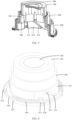
FIG. 1 is an exploded view of a camera module disclosed in a first embodiment of this application; -
FIG. 2 andFIG. 3 are schematic structural diagrams of the camera module disclosed in the first embodiment of this application in different states; -
FIG. 4 is an exploded view of a camera module disclosed in a second embodiment of this application; -
FIG. 5 is a cross-sectional view of the camera module disclosed in the second embodiment of this application; and -
FIG. 6 andFIG. 7 are schematic structural diagrams of the camera module disclosed in the second embodiment of this application in different states. -
- 100. first lens barrel;
- 200. rotating assembly; 210. body member; 211. guide slot; 212. first action portion; 213. third action portion; 214. third spiral guide slot; 215. second limiting straight slot; 220. transmission member; 221. third end; 222. fourth end; 223. rack portion; 224. rod portion; 225. guide portion; 226. second action portion; 227. first support convex portion; 228. second support convex portion; 240. mounting member;
- 300. second lens barrel;
- 400. elastic member;
- 500. first lens;
- 600. base;
- 700. drive lens barrel; 710. third fitting convex portion; and 720. third limiting straight slot.
- The following clearly and completely describes the technical solutions in the embodiments of this application with reference to the accompanying drawings in the embodiments of this application. Apparently, the described embodiments are some but not all of the embodiments of this application. All other embodiments obtained by persons of ordinary skill in the art based on the embodiments of this application without creative efforts shall fall within the protection scope of this application.
- The terms "first", "second", and the like in the specification and claims of this application are used to distinguish between similar objects rather than to describe a specific order or sequence. It should be understood that data used in this way are interchangeable in appropriate circumstances such that the embodiments of this application can be implemented in an order other than those illustrated or described herein. In addition, "first" and "second" are typically used to distinguish objects of a same type and do not limit quantities of the objects. For example, there may be one or more first objects. In addition, in this specification and claims, "and/or" indicates at least one of the connected objects, and the character "/" generally indicates an "or" relationship between the contextually associated objects.
- The following describes in detail the camera module and electronic device provided in the embodiments of this application through specific embodiments and application scenarios thereof with reference to the accompanying drawings.
- As shown in
FIG. 1 to FIG. 7 , an embodiment of this application provides a camera module. The camera module includes abase 600, a photosensitive chip, afirst lens barrel 100, afirst lens 500, a rotatingassembly 200, anelastic member 400, and a drive mechanism. - The photosensitive chip is disposed in the
base 600, and the base 600 may be provided with other components of the camera module in addition to the photosensitive chip. In addition, thebase 600 may include other parts in addition to the parts shown inFIG. 5 . Thefirst lens barrel 100 is provided with thefirst lens 500, thefirst lens 500 is disposed opposite the photosensitive chip, and thefirst lens 500 and the photosensitive chip may be disposed along an optical axis direction of the camera module. The photosensitive chip may be configured to receive light emitted through thefirst lens 500 and ultimately convert an optical signal into a digital image signal, so as to obtain an image. - The
rotating assembly 200 sleeves thefirst lens barrel 100, and thefirst lens barrel 100 is connected to therotating assembly 200 via a first fitting convex portion and a first spiral guide slot. Therotating assembly 200 includes abody member 210 and atransmission member 220 that are disposed separately, a first end of theelastic member 400 is connected to thebody member 210, and a second end of theelastic member 400 is connected to thetransmission member 220. Optionally, of thebody member 210 and thefirst lens barrel 100, one is provided with the first fitting convex portion and the other is provided with the first spiral guide slot, so that thebody member 210 can directly drive thefirst lens barrel 100 to stretch and retract. Since thebody member 210 and thetransmission member 220 are disposed separately, movements of the two can be separate. In other words, thetransmission member 220 can transfer a drive force to thebody member 210 via theelastic member 400, causing thebody member 210 to rotate, and when thetransmission member 220 transfers no drive force to thebody member 210, thebody member 210 can rotate with respect to thetransmission member 220 under the action of an external force. Optionally, theelastic member 400 may be a spring, and theelastic member 400 and thebody member 210 may just abut against each other, or may be connected through welding, snap-fitting, or the like. Similarly, theelastic member 400 and thebody member 210 may just abut against each other, or may be connected through welding, snap-fitting, or the like. In addition, a cross section of theelastic member 400 may be the same in shape as a portion, of thetransmission member 220, where theelastic member 400 is disposed. For example, the cross section of theelastic member 400 may be circular, rectangular, triangular, or the like. This is not limited in this embodiment of this application. - The drive mechanism is connected to the
transmission member 220, and the drive mechanism drives, via thetransmission member 220, theelastic member 400, and thebody member 210 in turn, thefirst lens barrel 100 to move along a first direction with fitting of the first fitting convex portion and the first spiral guide slot, the first direction being a direction approaching or leaving the photosensitive chip. Optionally, the drive mechanism herein may include components such as a motor and a transmission gear. When the drive mechanism outputs a drive force, thetransmission member 220 rotates under the action of this drive force, thetransmission member 220 drives thebody member 210 to rotate via theelastic member 400, and with fitting of the first fitting convex portion and the first spiral guide slot, thefirst lens barrel 100 can move along a direction leaving the photosensitive chip, thereby causing thefirst lens barrel 100 to stretch out. When the drive mechanism outputs a reversed drive force, thetransmission member 220 drives thebody member 210 to rotate via theelastic member 400, and with fitting of the first fitting convex portion and the first spiral guide slot, thefirst lens barrel 100 can move along a direction approaching the photosensitive chip, thereby causing thefirst lens barrel 100 to retract. - The foregoing describes the process of the drive mechanism driving the
first lens barrel 100 to move. When thefirst lens barrel 100 is in a stretching state, once thefirst lens barrel 100 is subjected to an external force, thefirst lens barrel 100 exhibits a trend of retracting, in which case although the drive mechanism does not work, thefirst lens barrel 100 can still move due to the presence of theelastic member 400, that is, in a case that thefirst lens barrel 100 is subjected to an external force, theelastic member 400 makes thefirst lens barrel 100 move along the direction approaching the photosensitive chip. Specifically, if thefirst lens barrel 100 exhibits a trend of moving along the direction approaching the photosensitive chip, thefirst lens barrel 100 can drive thebody member 210 to rotate, and thebody member 210 further drives one end of theelastic member 400 to move. Since the other end of theelastic member 400 is connected to thetransmission member 220 and thetransmission member 220 does not move, theelastic member 400 deforms, thereby absorbing the external force on thefirst lens barrel 100. After the external force on thefirst lens barrel 100 disappears, theelastic member 400 resumes from deformation, so that thebody member 210 drives thefirst lens barrel 100 to reset to the stretching state. In this way, the camera module can continue to work with thefirst lens barrel 100 stretching out, without the need for the drive mechanism to drive thefirst lens barrel 100 to stretch out again. - In this embodiment of this application, when the camera module requires zooming, the drive mechanism drives, via the
transmission member 220, theelastic member 400, and thebody member 210 in turn, thefirst lens barrel 100 to move along the first direction with fitting of the first fitting convex portion and the first spiral guide slot, so as to drive thefirst lens 500 to leave or approach the photosensitive chip; and when the camera module in the stretching state is subjected to a pressure due to falling, collision, artificial press, and other situations, thefirst lens barrel 100 drives thebody member 210 to rotate, then thebody member 210 applies a pressure to theelastic member 400, causing theelastic member 400 to deform, while thetransmission member 220 can keep still. Theelastic member 400 can convert dynamic potential energy, generated by the camera module under pressure, into its own elastic potential energy, thereby providing buffering, so that the first fitting convex portion is not prone to breakage due to extrusion, and other parts of the camera module are also not prone to an impact force. Therefore, this embodiment can solve the problem of short service life of the camera module. - As mentioned above, the
body member 210 can directly drive thefirst lens barrel 100. In other embodiments, the camera module may further include asecond lens barrel 300 and adrive lens barrel 700. The base 600 sleeves at least part of thebody member 210, and thebase 600 is provided with a second spiral guide slot and a first limiting straight slot. Thebody member 210 is provided with a thirdspiral guide slot 214 and a second limitingstraight slot 215. Thesecond lens barrel 300 is provided with a second fitting convex portion, where the second fitting convex portion fits with the second spiral guide slot, and the second fitting convex portion also fits with the second limitingstraight slot 215 of thebody member 210. Thedrive lens barrel 700 is provided with a third fittingconvex portion 710 and a third limitingstraight slot 720, where the third fittingconvex portion 710 fits with both the thirdspiral guide slot 214 and the first limiting straight slot. Thefirst lens barrel 100 is provided with the first fitting convex portion, thesecond lens barrel 300 is provided with the first spiral guide slot, and the first fitting convex portion fits with both the first spiral guide slot and the third limitingstraight slot 720. The first limiting straight slot, the second limitingstraight slot 215, and the third limitingstraight slot 720 herein all extend along the first direction. When the drive mechanism drives thebody member 210 to rotate, thesecond lens barrel 300 rotates and moves along the first direction with fitting of the second fitting convex portion with the second spiral guide slot and fitting of the second fitting convex portion with the second limitingstraight slot 215, thedrive lens barrel 700 only moves along the first direction with fitting of the third fittingconvex portion 710 with the thirdspiral guide slot 214 and fitting of the third fittingconvex portion 710 with the first limiting straight slot, and thefirst lens barrel 100 only moves along the first direction with fitting of the first fitting convex portion with the first spiral guide slot and fitting of the first fitting convex portion with the third limitingstraight slot 720. In this embodiment, both thefirst lens barrel 100 and thesecond lens barrel 300 can move along the first direction, so that thefirst lens 500 has a greater variation range of position with respect to the photosensitive chip, thereby improving a zoom effect of the camera module. When thefirst lens barrel 100 is subjected to an external force, thefirst lens barrel 100 moves along the direction approaching the photosensitive chip so as to drive thesecond lens barrel 300 to rotate and gradually approach the photosensitive chip, thesecond lens barrel 300 then drives thedrive lens barrel 700 to move along the direction approaching the photosensitive chip, and thedrive lens barrel 700 then drives thebody member 210 to rotate, while thetransmission member 220 keeps still. - It should be noted that the solution that the
elastic member 400 absorbs an external force disclosed in this embodiment of this application may be applicable to any camera module with abody member 210 and atransmission member 220. This is not limited in this embodiment of this application. - The
body member 210 may be an arc-shaped structure with a notch, but the entire center of gravity of the camera module is prone to change whensuch body member 210 rotates, which results in deteriorated stability of the camera module. In view of this, thebody member 210 may be arranged as an annular member, in which case thetransmission member 220 and theelastic member 400 are both disposed in a circumferential direction of thebody member 210. Theelastic member 400 may be designed in correspondence to a local part of thetransmission member 220, so that theelastic member 400 is neither too long nor too short, thereby not only guaranteeing elastic deformability of theelastic member 400 but also reducing space occupied by theelastic member 400, so as to facilitate arrangement of other components of the camera module. - In an optional embodiment, as shown in
FIG. 1 to FIG. 3 , thetransmission member 220 has athird end 221 and afourth end 222, thethird end 221 and thefourth end 222 being apart from each other, to be specific, thetransmission member 220 is not a closed annular structure but is instead an arc-shaped component with a notch, and due to the presence of the notch, theelastic member 400 can sleeve thetransmission member 220 through the notch. In this embodiment, thetransmission member 220 adopts a rod component with a relatively simple structure, and theelastic member 400 can directly sleeves thetransmission member 220. In this way, in this embodiment, the structure and assembly of the camera module can be simplified, the processing costs of the camera module can be reduced, and the camera module can have more space for arranging other components. - The
transmission member 220 may be entirely disposed outside thebody member 210. In another optional embodiment, thebody member 210 is provided with aguide slot 211 and afirst action portion 212, where theguide slot 211 may extend along the circumferential direction of thebody member 210, thetransmission member 220 fits with theguide slot 211, thefirst action portion 212 is connected to the first end of theelastic member 400, and a portion of thetransmission member 220 is disposed between a side wall of theguide slot 211 and thefirst action portion 212. When thefirst lens barrel 100 is subjected to an external force, thebody member 210 rotates relative to thetransmission member 220, and at this time, theguide slot 211 fits with thetransmission member 220 to provide a guiding effect, so that thebody member 210 rotates more smoothly. In addition, thefirst action portion 212 may apply a force to theelastic member 400 to drive theelastic member 400 to deform. In this embodiment, at least a portion of thetransmission member 220 is accommodated in theguide slot 211, allowing thetransmission member 220 to take up less extra space, and thus facilitating arrangement of other components of the camera module. - Optionally, the
transmission member 220 may include arack portion 223 and arod portion 224, where therack portion 223 is connected to the drive mechanism, therack portion 223 is provided with asecond action portion 226 at an end, and the second end of theelastic member 400 is connected to thesecond action portion 226. In this embodiment, the structure of therack portion 223 is directly utilized to implement the connection between thetransmission member 220 and theelastic member 400, without the need for additionally providing a component to implement the connection between thetransmission member 220 and theelastic member 400, thereby simplifying the structure of the camera module, and also facilitating layout of the components of the camera module. In addition, when thebody member 210 is provided with theguide slot 211 and thefirst action portion 212, theguide slot 211 may be provided with an avoidance notch on a side facing away from an optical axis of thefirst lens 500, and the avoidance notch can avoid therack portion 223, so that the drive mechanism can be connected to therack portion 223. - Further, the
transmission member 220 further includes aguide portion 225, where theguide portion 225 is connected to therod portion 224 via therack portion 223, and theguide portion 225 can fit with theguide slot 211, so as to further enhance smoothness and stability of thebody member 210 during rotation. - In another optional embodiment, as shown in
FIG. 4 to FIG. 6 , the rotatingassembly 200 further includes a mountingmember 240, the mountingmember 240 and thetransmission member 220 are disposed separately and connected to each other, and theelastic member 400 sleeves the mountingmember 240. In this embodiment, the second end of theelastic member 400 is connected to thetransmission member 220 via the mountingmember 240. Since theelastic member 400 can be mounted via the additionally provided mountingmember 240, the structural design of theelastic member 400 is not likely to be limited by thetransmission member 220, and therefore theelastic member 400 can be more flexibly arranged, allowing theelastic member 400 to have stronger capability of absorbing an external force. Optionally, the mountingmember 240 may be an arc-shaped rod component, facilitating mounting of theelastic member 400. - Further, the
transmission member 220 may be arranged as an annular member, making the camera module more stable during telescopic movement. In addition, theannular transmission member 220 has higher structural strength, which not only facilitates transfer of a drive force output by the drive mechanism but thetransmission member 220 can also withstand a force exerted by theelastic member 400, preventing such force from causing damage to thetransmission member 220 and the drive mechanism. In this embodiment, thetransmission member 220 may likewise include arack portion 223, where therack portion 223 may be disposed at a local part of thetransmission member 220, or may be arranged in an annular shape. This is not limited in this embodiment of this application. - The
elastic member 400 may be disposed on an inner side or outer side of thetransmission member 220. To be specific, theelastic member 400 and thetransmission member 220 may be arranged along a direction perpendicular to the optical axis of the camera module. In another embodiment, thetransmission member 220 and theelastic member 400 are arranged along a direction parallel to the optical axis of the camera module. As space on the inner side and outer side of thetransmission member 220 is usually insufficient, while space above or below thetransmission member 220 is relatively large, the latter embodiment is more conducive to a compact design of the camera module. - Optionally, the
transmission member 220 is provided with a first supportconvex portion 227 and a second supportconvex portion 228, and the mountingmember 240 is connected to both the first supportconvex portion 227 and the second supportconvex portion 228. Optionally, the first supportconvex portion 227 and the second supportconvex portion 228 may each be provided with a recess, two ends of the mountingmember 240 are respectively disposed at the recess of the first supportconvex portion 227 and the recess of the second supportconvex portion 228, and at least one end of the mountingmember 240 fits with the recess in a limiting manner, so that the mountingmember 240 does not move with respect to thetransmission member 220. It should be noted that the mountingmember 240 may rotate with respect to thetransmission member 220 or may remain completely fixed with respect to thetransmission member 220. - The first support
convex portion 227 and second supportconvex portion 228 may be only used to support the mountingmember 240. However, to fully utilize the structure of the second supportconvex portion 228, thebody member 210 may be provided with athird action portion 213, where thethird action portion 213 may protrude with respect to an outer peripheral surface of thebody member 210, the first end of theelastic member 400 is connected to thethird action portion 213, and thethird action portion 213 may fit with the second supportconvex portion 228 in a limiting manner. The second end of theelastic member 400 is connected to the first supportconvex portion 227. In this embodiment, the second supportconvex portion 228 can be used to assist in limiting a position of thebody member 210 with respect to thetransmission member 220, so as to prevent excessive rotation or unstable rotation of thebody member 210 due to the action of theelastic member 400 or other factors, thus allowing for more stable and reliable zooming of the camera module. - One or a plurality of
elastic members 400 may be provided. When thebody member 210 is an annular member, at least twoelastic members 400 are provided, and theelastic members 400 are spaced apart along a circumferential direction of thebody member 210. In this case, theelastic members 400 can absorb external forces at multiple positions, preventing unbalanced loading of the camera module, and thus improving reliability of the camera module during operation. - An embodiment of this application further discloses an electronic device, where the electronic device includes the camera module according to any one of the foregoing embodiments.
- The electronic device disclosed in this embodiment of this application may be a smartphone, a tablet computer, an e-book reader, a wearable device (for example, a smart watch), a game console, or other devices. A specific type of the electronic device is not limited in this embodiment of this application.
- The embodiments of this application have been described with reference to the accompanying drawings. However, this application is not limited to the foregoing specific implementations. These specific implementations are merely for illustration rather than limitation. Inspired by this application, persons of ordinary skill in the art may develop many other forms which do not depart from the essence of this application and the protection scope of the claims, and all such forms shall fall within the protection scope of this application.
Claims (11)
- A camera module, comprising a photosensitive chip, a first lens barrel, a first lens, a rotating assembly, an elastic member, and a drive mechanism, whereinthe first lens barrel is provided with the first lens, the first lens is disposed opposite the photosensitive chip, the rotating assembly sleeves the first lens barrel, and the first lens barrel is connected to the rotating assembly via a first fitting convex portion and a first spiral guide slot;the rotating assembly comprises a body member and a transmission member that are disposed separately, a first end of the elastic member is connected to the body member, a second end of the elastic member is connected to the transmission member, and the drive mechanism is connected to the transmission member;the drive mechanism drives, via the transmission member, the elastic member, and the body member in turn, the first lens barrel to move along a first direction with fitting of the first fitting convex portion and the first spiral guide slot, the first direction being a direction approaching or leaving the photosensitive chip; andin a case that the first lens barrel is subjected to an external force, the elastic member makes the first lens barrel move along a direction approaching the photosensitive chip.
- The camera module according to claim 1, wherein the body member is an annular member, and the transmission member and the elastic member are both disposed in a circumferential direction of the body member.
- The camera module according to claim 1, wherein the transmission member has a third end and a fourth end, the third end and the fourth end being apart from each other, and the elastic member sleeves the transmission member.
- The camera module according to claim 3, wherein the body member is provided with a guide slot and a first action portion, the transmission member fits with the guide slot, the first action portion is connected to the first end, and a portion of the transmission member is disposed between a side wall of the guide slot and the first action portion.
- The camera module according to claim 3, wherein the transmission member comprises a rack portion and a rod portion, wherein the rack portion is connected to the drive mechanism, the rack portion is provided with a second action portion at an end, and the second end is connected to the second action portion.
- The camera module according to claim 1, wherein the rotating assembly further comprises a mounting member, the mounting member and the transmission member are disposed separately and connected to each other, and the elastic member sleeves the mounting member.
- The camera module according to claim 6, wherein the transmission member is an annular member.
- The camera module according to claim 6, wherein the transmission member and the elastic member are arranged along a direction parallel to an optical axis of the camera module.
- The camera module according to claim 6, wherein the transmission member is provided with a first support convex portion and a second support convex portion, the mounting member is connected to both the first support convex portion and the second support convex portion, the body member is provided with a third action portion, the first end is connected to the third action portion, the third action portion fits with the second support convex portion in a limiting manner, and the second end is connected to the first support convex portion.
- The camera module according to claim 1, wherein the body member is an annular member, at least two elastic members are provided, and the elastic members are spaced apart along a circumferential direction of the body member.
- An electronic device, comprising the camera module according to any one of claims 1 to 10.
Applications Claiming Priority (2)
| Application Number | Priority Date | Filing Date | Title |
|---|---|---|---|
| CN202110997105.9A CN115734050B (en) | 2021-08-27 | 2021-08-27 | Camera module and electronic equipment |
| PCT/CN2022/113912 WO2023025090A1 (en) | 2021-08-27 | 2022-08-22 | Camera module and electronic apparatus |
Publications (2)
| Publication Number | Publication Date |
|---|---|
| EP4395343A1 true EP4395343A1 (en) | 2024-07-03 |
| EP4395343A4 EP4395343A4 (en) | 2024-12-25 |
Family
ID=85290346
Family Applications (1)
| Application Number | Title | Priority Date | Filing Date |
|---|---|---|---|
| EP22860436.9A Pending EP4395343A4 (en) | 2021-08-27 | 2022-08-22 | Camera module and electronic apparatus |
Country Status (5)
| Country | Link |
|---|---|
| US (1) | US20240179388A1 (en) |
| EP (1) | EP4395343A4 (en) |
| JP (1) | JP7770539B2 (en) |
| CN (1) | CN115734050B (en) |
| WO (1) | WO2023025090A1 (en) |
Families Citing this family (2)
| Publication number | Priority date | Publication date | Assignee | Title |
|---|---|---|---|---|
| CN112702494B (en) * | 2020-12-28 | 2022-03-25 | 维沃移动通信有限公司 | Electronic equipment and camera module thereof |
| CN119743674B (en) * | 2024-12-23 | 2025-08-26 | 中山市央果电子科技有限公司 | A tracking camera control method and system for live broadcast pan-tilt head |
Family Cites Families (10)
| Publication number | Priority date | Publication date | Assignee | Title |
|---|---|---|---|---|
| KR20000009826U (en) * | 1998-11-12 | 2000-06-05 | 이중구 | Barrel drive of the zoom camera |
| JP2007034070A (en) | 2005-07-28 | 2007-02-08 | Nidec Copal Corp | Lens driving unit |
| JP2011069886A (en) * | 2009-09-24 | 2011-04-07 | Canon Inc | Lens barrel and optical device |
| JP5791404B2 (en) * | 2011-07-12 | 2015-10-07 | キヤノン株式会社 | Lens barrel and imaging device having the same |
| WO2014115760A1 (en) * | 2013-01-25 | 2014-07-31 | オリンパスイメージング株式会社 | Lens barrel |
| KR102468129B1 (en) * | 2016-06-01 | 2022-11-22 | 삼성전자주식회사 | Electronic device and manufacturing method thereof |
| CN111147721B (en) * | 2019-12-26 | 2021-07-30 | 诚瑞光学(常州)股份有限公司 | Imaging device, electronic apparatus, and method for using electronic apparatus |
| CN111212216B (en) * | 2020-04-23 | 2020-08-04 | 瑞声通讯科技(常州)有限公司 | Lens transmission device |
| CN112526700B (en) * | 2020-12-21 | 2023-05-12 | 维沃移动通信有限公司 | Camera module and electronic equipment |
| CN113109918A (en) * | 2021-05-10 | 2021-07-13 | 中山联合光电研究院有限公司 | Retractable zoom lens capable of retracting under stress and camera |
-
2021
- 2021-08-27 CN CN202110997105.9A patent/CN115734050B/en active Active
-
2022
- 2022-08-22 JP JP2024510525A patent/JP7770539B2/en active Active
- 2022-08-22 EP EP22860436.9A patent/EP4395343A4/en active Pending
- 2022-08-22 WO PCT/CN2022/113912 patent/WO2023025090A1/en not_active Ceased
-
2024
- 2024-02-07 US US18/435,512 patent/US20240179388A1/en active Pending
Also Published As
| Publication number | Publication date |
|---|---|
| US20240179388A1 (en) | 2024-05-30 |
| JP7770539B2 (en) | 2025-11-14 |
| JP2024530973A (en) | 2024-08-27 |
| CN115734050A (en) | 2023-03-03 |
| EP4395343A4 (en) | 2024-12-25 |
| WO2023025090A1 (en) | 2023-03-02 |
| CN115734050B (en) | 2025-10-31 |
Similar Documents
| Publication | Publication Date | Title |
|---|---|---|
| US20240179388A1 (en) | Camera module and electronic device | |
| US11536936B2 (en) | Folded camera | |
| JP4964654B2 (en) | Lens barrel, camera and information equipment | |
| US7929228B2 (en) | Image pickup apparatus having lens barrel | |
| CN113691698B (en) | Camera module and electronic equipment | |
| EP4354845A1 (en) | Photographing apparatus and electronic device | |
| JP5298737B2 (en) | Lens barrel, camera, portable information terminal device, image input device, and lens barrel | |
| US8570665B2 (en) | Lens barrel having cam cylinder with cam groove | |
| US12326762B2 (en) | Flip function assembly and electronic device | |
| CN110336900A (en) | Camera module and mobile terminal | |
| CN112433336A (en) | Telescopic zoom lens | |
| US8456756B2 (en) | Zoom lens barrel assembly | |
| US20240280780A1 (en) | Camera Module and Electronic Device | |
| CN107817570B (en) | Lens barrel | |
| EP4407971A1 (en) | Camera module and electronic apparatus | |
| JP6393896B2 (en) | Lens barrel | |
| EP2921891B1 (en) | Lens barrel | |
| US20160065815A1 (en) | Lens barrel and image pickup apparatus | |
| US20150049392A1 (en) | Zoom lens assembly | |
| EP4407358A1 (en) | Camera module and electronic device | |
| JPWO2015049813A1 (en) | Lens barrel | |
| EP1903366A2 (en) | Collapsible Lens Barrel | |
| JP2010066693A (en) | Lens barrel | |
| JP2000187145A (en) | Lens barrel | |
| CN115734046A (en) | Camera module and electronic equipment |
Legal Events
| Date | Code | Title | Description |
|---|---|---|---|
| STAA | Information on the status of an ep patent application or granted ep patent |
Free format text: STATUS: THE INTERNATIONAL PUBLICATION HAS BEEN MADE |
|
| PUAI | Public reference made under article 153(3) epc to a published international application that has entered the european phase |
Free format text: ORIGINAL CODE: 0009012 |
|
| STAA | Information on the status of an ep patent application or granted ep patent |
Free format text: STATUS: REQUEST FOR EXAMINATION WAS MADE |
|
| 17P | Request for examination filed |
Effective date: 20240311 |
|
| AK | Designated contracting states |
Kind code of ref document: A1 Designated state(s): AL AT BE BG CH CY CZ DE DK EE ES FI FR GB GR HR HU IE IS IT LI LT LU LV MC MK MT NL NO PL PT RO RS SE SI SK SM TR |
|
| DAV | Request for validation of the european patent (deleted) | ||
| DAX | Request for extension of the european patent (deleted) | ||
| A4 | Supplementary search report drawn up and despatched |
Effective date: 20241121 |
|
| RIC1 | Information provided on ipc code assigned before grant |
Ipc: G02B 7/08 20210101ALI20241115BHEP Ipc: G02B 7/02 20210101ALI20241115BHEP Ipc: G02B 7/10 20210101ALI20241115BHEP Ipc: H04N 23/00 20230101AFI20241115BHEP |