EP4395160A1 - Synchronous motor driving device and synchronous motor driving method - Google Patents
Synchronous motor driving device and synchronous motor driving method Download PDFInfo
- Publication number
- EP4395160A1 EP4395160A1 EP22860920.2A EP22860920A EP4395160A1 EP 4395160 A1 EP4395160 A1 EP 4395160A1 EP 22860920 A EP22860920 A EP 22860920A EP 4395160 A1 EP4395160 A1 EP 4395160A1
- Authority
- EP
- European Patent Office
- Prior art keywords
- direct current
- synchronous motor
- current
- basis
- motor driving
- Prior art date
- Legal status (The legal status is an assumption and is not a legal conclusion. Google has not performed a legal analysis and makes no representation as to the accuracy of the status listed.)
- Pending
Links
Images


Classifications
-
- H—ELECTRICITY
- H02—GENERATION; CONVERSION OR DISTRIBUTION OF ELECTRIC POWER
- H02P—CONTROL OR REGULATION OF ELECTRIC MOTORS, ELECTRIC GENERATORS OR DYNAMO-ELECTRIC CONVERTERS; CONTROLLING TRANSFORMERS, REACTORS OR CHOKE COILS
- H02P21/00—Arrangements or methods for the control of electric machines by vector control, e.g. by control of field orientation
- H02P21/22—Current control, e.g. using a current control loop
-
- H—ELECTRICITY
- H02—GENERATION; CONVERSION OR DISTRIBUTION OF ELECTRIC POWER
- H02P—CONTROL OR REGULATION OF ELECTRIC MOTORS, ELECTRIC GENERATORS OR DYNAMO-ELECTRIC CONVERTERS; CONTROLLING TRANSFORMERS, REACTORS OR CHOKE COILS
- H02P6/00—Arrangements for controlling synchronous motors or other dynamo-electric motors using electronic commutation dependent on the rotor position; Electronic commutators therefor
- H02P6/28—Arrangements for controlling current
-
- B—PERFORMING OPERATIONS; TRANSPORTING
- B60—VEHICLES IN GENERAL
- B60T—VEHICLE BRAKE CONTROL SYSTEMS OR PARTS THEREOF; BRAKE CONTROL SYSTEMS OR PARTS THEREOF, IN GENERAL; ARRANGEMENT OF BRAKING ELEMENTS ON VEHICLES IN GENERAL; PORTABLE DEVICES FOR PREVENTING UNWANTED MOVEMENT OF VEHICLES; VEHICLE MODIFICATIONS TO FACILITATE COOLING OF BRAKES
- B60T13/00—Transmitting braking action from initiating means to ultimate brake actuator with power assistance or drive; Brake systems incorporating such transmitting means, e.g. air-pressure brake systems
- B60T13/74—Transmitting braking action from initiating means to ultimate brake actuator with power assistance or drive; Brake systems incorporating such transmitting means, e.g. air-pressure brake systems with electrical assistance or drive
-
- H—ELECTRICITY
- H02—GENERATION; CONVERSION OR DISTRIBUTION OF ELECTRIC POWER
- H02P—CONTROL OR REGULATION OF ELECTRIC MOTORS, ELECTRIC GENERATORS OR DYNAMO-ELECTRIC CONVERTERS; CONTROLLING TRANSFORMERS, REACTORS OR CHOKE COILS
- H02P23/00—Arrangements or methods for the control of AC motors characterised by a control method other than vector control
- H02P23/14—Estimation or adaptation of motor parameters, e.g. rotor time constant, flux, speed, current or voltage
-
- H—ELECTRICITY
- H02—GENERATION; CONVERSION OR DISTRIBUTION OF ELECTRIC POWER
- H02P—CONTROL OR REGULATION OF ELECTRIC MOTORS, ELECTRIC GENERATORS OR DYNAMO-ELECTRIC CONVERTERS; CONTROLLING TRANSFORMERS, REACTORS OR CHOKE COILS
- H02P6/00—Arrangements for controlling synchronous motors or other dynamo-electric motors using electronic commutation dependent on the rotor position; Electronic commutators therefor
- H02P6/34—Modelling or simulation for control purposes
-
- H—ELECTRICITY
- H02—GENERATION; CONVERSION OR DISTRIBUTION OF ELECTRIC POWER
- H02P—CONTROL OR REGULATION OF ELECTRIC MOTORS, ELECTRIC GENERATORS OR DYNAMO-ELECTRIC CONVERTERS; CONTROLLING TRANSFORMERS, REACTORS OR CHOKE COILS
- H02P2207/00—Indexing scheme relating to controlling arrangements characterised by the type of motor
- H02P2207/05—Synchronous machines, e.g. with permanent magnets or DC excitation
Definitions
- the present invention relates to a configuration of a driving device for driving and controlling a synchronous motor and to control thereof, and particularly relates to technology which is effective when applied to an electric brake motor of an automobile, which requires high responsiveness and high reliability.
- the present invention further includes the steps of: (a) calculating a first direct current on the basis of a first voltage command value, a current value of a winding of a synchronous motor, and a battery voltage; (b) calculating a second direct current on the basis of a current value of the winding of the synchronous motor, a rotation speed of the synchronous motor, and a predetermined motor characteristic of the synchronous motor; (c) calculating inverter efficiency on the basis of the first direct current and the second direct current; (d) calculating an estimated direct current on the basis of the first direct current, the second direct current, and the inverter efficiency; and (e) correcting a current command value of the winding on the basis of the estimated direct current and a predetermined direct current limit value.
- the synchronous motor driving device 100 includes, as a main configuration, a current detection unit 300, a power converter 400, a current controller 500, a current command calculation unit 600, a coordinate conversion unit 700, a direct current estimation unit 800, and a direct current limiting unit 900, and drives a synchronous motor 200.
- the current sensors 300u, 300v, and 300w are arranged in each phase of the synchronous motor 200
- the current sensors may be arranged only in two phases (for example, the u-phase and the v-phase) by utilizing the fact that the sum of the symmetrical three-phase alternating currents is zero.
- a configuration in which the three-phase current of the synchronous motor 200 is obtained from the current flowing through the DC bus (not illustrated) of the power converter 400 may be adopted. With these configurations, the number of current sensors can be reduced, and cost reduction can be achieved.
- the direct current estimation unit 800 takes, as inputs, the d-axis current Id and the q-axis current Iq from the coordinate conversion unit 700, the d-axis voltage command Vd* and the q-axis voltage command Vq* from the current controller 500, a battery voltage Vbat, and the rotation speed ⁇ of the synchronous motor 200, and calculates Idc ⁇ , which is an estimated value for the direct current.
- the Idc ⁇ thus calculated is transmitted to the direct current limiting unit 900.
- Equation (1) yields the first direct current Idc1 ⁇ on the basis of the balance between the product of the direct current, which is the input power of the inverter, and the direct voltage, and the inner product of the voltage, which is the output voltage of the inverter, and the current.
- Equation (1) Because the inverter efficiency is not taken into account in the generally known Equation (1), an error always occurs. If the inverter efficiency ⁇ is measured in advance, the direct current can be accurately obtained, but because the inverter efficiency changes according to the operating voltage, the current, or the temperature, it is difficult to measure the inverter efficiency in advance.
- the second direct current calculation unit 820 takes, as inputs, the d-axis current Id, the q-axis current Iq, the motor rotation speed ⁇ , and the battery voltage Vbat, and calculates a second direct current Idc2 ⁇ .
- the second direct current calculation unit 820 is, for example, a block that calculates a direct current on the basis of motor characteristics, and uses Equations (3), (4), and (5) in the present embodiment.
- Vd ⁇ R ⁇ Id ⁇ ⁇ LqIq
- s is a Laplace operator.
- the first direct current Idc1 ⁇ is obtained by multiplying the actual direct current Idc by the inverter efficiency ⁇ . That is, it is a value including information on the inverter efficiency ⁇ .
- the second direct current Idc2 ⁇ is an ideal direct current which is based on the motor model representing the characteristics of the synchronous motor 200 and which does not take into account the inverter efficiency.
- the direct current can be accurately obtained.
- FL is a reference sign indicating a configuration corresponding to the front left
- Fr corresponds to the front right
- RL corresponds to the rear left
- Rr corresponds to the rear right.
- 3FL, 3Fr, 3RL, and 3Rr are the front-left wheel, the front-right wheel, the rear-left wheel, and the rear-right wheel, respectively.
- the vehicle 1 is configured as described above, and by distributing the outputs of the synchronous motor driving devices 100 and 100' to the four electric brakes 4 (4FL, 4Fr, 4RL, 4Rr), the four electric brakes that respectively brake the four wheels are integrally driven and controlled.
Landscapes
- Engineering & Computer Science (AREA)
- Power Engineering (AREA)
- Transportation (AREA)
- Mechanical Engineering (AREA)
- Control Of Ac Motors In General (AREA)
Abstract
Description
- The present invention relates to a configuration of a driving device for driving and controlling a synchronous motor and to control thereof, and particularly relates to technology which is effective when applied to an electric brake motor of an automobile, which requires high responsiveness and high reliability.
- In recent years, advances have been made in the electrification of auxiliary components such as the steering wheel and brake units of an automobile. Because a conventional hydraulic system can be eliminated through electrification of auxiliary components, improved maintainability and improvements in automobile operability and controllability are expected. In a motorized auxiliary machine of this kind, generally, DC power of an auxiliary battery is converted into AC power by a power conversion device such as an inverter, and actuators of the steering wheel and the brakes and the like are operated by driving a synchronous motor.
- In a case where important parts of an automobile such as the steering wheel and the brakes are motorized, a redundant configuration is desirable so that driving can be continued even when an electric component such as a synchronous motor or an inverter fails. For example, by changing the motor from a conventional three-phase winding to a multiple three-phase winding and providing multiple inverters, the operation is continued even if failure occurs.
- Meanwhile, there is a limit to the electric power that can be supplied from the auxiliary battery, and the electric power consumed by the steering and the braking may be determined in the vehicle design. In such cases, measures may be taken so that the direct current outputted from the auxiliary battery does not exceed the limit value.
- As a countermeasure to the foregoing problem, there is a method, as per
Patent Literature 1, for example, in which a sensor for detecting a direct current is provided, and in a case where the direct current exceeds a limit value, the inverter output is reduced to limit the output of the direct current. - PTL 1:
JP 2012-175770 A -
Patent Literature 1 discloses a technique in which a battery state is detected using a sensor or the like and a synchronous motor is controlled based on the battery state to allocate power from the battery. - However, because additional configurations such as a sensor or a hardware filter are required, there is a risk of causing an increase in cost and an increase in device size.
- In addition, in the above-described multiple winding structure, it is necessary to provide a sensor in each winding system, which leads to a further increase in cost.
- As one possible method for limiting the direct current while preventing an increase in cost, there is a method, constituting generally known technology, in which active power is calculated from the output voltage and the output current of an inverter, and the active power is divided by a battery voltage to obtain the direct current.
- However, because the efficiency of the inverter is not taken into account, a direct current estimation error occurs, and therefore the direct current cannot be appropriately estimated and may exceed the limit value.
- Therefore, an object of the present invention is to provide a highly reliable synchronous motor driving device that is capable of highly accurately estimating and limiting a direct current, without the need for an additional configuration such as a dedicated current detection sensor, and a synchronous motor driving method using same.
- In order to solve the foregoing problems, the present invention includes a first direct current calculation unit that calculates a first direct current on the basis of a first voltage command value, a current value of a winding of a synchronous motor, and a battery voltage; a second direct current calculation unit that calculates a second direct current on the basis of a current value of the winding of the synchronous motor, a rotation speed of the synchronous motor, and a predetermined motor characteristic of the synchronous motor; a model error extraction unit that calculates inverter efficiency on the basis of the first direct current and the second direct current; a direct current correction unit that calculates an estimated direct current on the basis of the first direct current, the second direct current, and the inverter efficiency; and a direct current limiting unit that corrects a current command value of the winding on the basis of the estimated direct current and a predetermined direct current limit value.
- The present invention further includes the steps of: (a) calculating a first direct current on the basis of a first voltage command value, a current value of a winding of a synchronous motor, and a battery voltage; (b) calculating a second direct current on the basis of a current value of the winding of the synchronous motor, a rotation speed of the synchronous motor, and a predetermined motor characteristic of the synchronous motor; (c) calculating inverter efficiency on the basis of the first direct current and the second direct current; (d) calculating an estimated direct current on the basis of the first direct current, the second direct current, and the inverter efficiency; and (e) correcting a current command value of the winding on the basis of the estimated direct current and a predetermined direct current limit value.
- According to the present invention, it is possible to realize a highly reliable synchronous motor driving device that is capable of highly accurately estimating and limiting a direct current, without the need for an additional configuration such as a dedicated current detection sensor, and a synchronous motor driving method using same.
- As a result, it is possible to contribute to improvements in the reliability of a synchronous motor and automobile electric brakes whereon the synchronous motor is mounted while suppressing an increase in cost.
- Problems, configurations, advantageous effects other than those described above will be clarified by the following descriptions of the embodiments.
-
- [
FIG. 1] FIG. 1 is a block diagram illustrating a primary function of a synchronous motor driving device according to a first embodiment of the present invention. - [
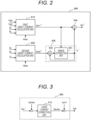
FIG. 2] FIG. 2 is a block diagram illustrating a primary function of a direct current estimation unit inFIG. 1 . - [
FIG. 3] FIG. 3 is a block diagram illustrating a primary function of the direct current limiting unit inFIG. 1 . - [
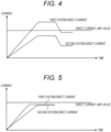
FIG. 4] FIG. 4 is a diagram schematically illustrating a direct current from a conventional synchronous motor driving device. - [
FIG. 5] FIG. 5 is a diagram schematically illustrating a direct current from a synchronous motor driving device according to the first embodiment of the present invention. - [
FIG. 6] FIG. 6 is a diagram illustrating a schematic configuration of a vehicle according to a second embodiment of the present invention. - Hereinafter, embodiments of the present invention will be described with reference to the drawings. Note that, in the drawings, the same constituent elements are denoted by the same reference signs, and detailed descriptions of duplicate constituent elements are omitted.
- Furthermore, the descriptions and drawings hereinbelow are examples to illustrate the present invention, and omissions and simplifications are made, as appropriate, to clarify the invention. The present invention can also be carried out in various other forms. Unless otherwise specified, each constituent element may be singular or plural.
- A synchronous motor driving device according to a first embodiment of the present invention and a synchronous motor driving method using same will be described with reference to
FIGS. 1 to 5 . Note thatFIG. 4 is a diagram of a direct current from a conventional synchronous motor driving device, which is illustrated to facilitate understanding of the advantageous effects of the present invention. -
FIG. 1 is a functional block diagram of a synchronousmotor driving device 100 according to the present embodiment. - As illustrated in
FIG. 1 , the synchronousmotor driving device 100 according to the present embodiment includes, as a main configuration, acurrent detection unit 300, apower converter 400, acurrent controller 500, a currentcommand calculation unit 600, acoordinate conversion unit 700, a directcurrent estimation unit 800, and a direct current limitingunit 900, and drives asynchronous motor 200. - The
synchronous motor 200 is, for example, a permanent magnet-type synchronous motor, and is configured using a permanent magnet (ferromagnetic body) as the rotor and using an armature winding as the stator. Note that, in the present embodiment, thesynchronous motor 200 is a dual three-phase winding motor, and is configured including two three-phase windings. - The synchronous
motor driving device 100 supplies AC power to one dual three-phase winding of the dual three-phase windings. Further, a synchronous motor driving device 100' having the same configuration as the synchronousmotor driving device 100 is provided, and the synchronous motor driving device 100' supplies AC power to the other three-phase winding to drive the dual three-phase winding motor. - The
current detection unit 300 includescurrent sensors synchronous motor 200. Thecurrent sensors synchronous motor 200. Thecurrent detection unit 300 detects the currents Iu, Iv, and Iw and outputs the currents to thecoordinate conversion unit 700. - Note that, although an example in which the
current sensors synchronous motor 200 is illustrated, the current sensors may be arranged only in two phases (for example, the u-phase and the v-phase) by utilizing the fact that the sum of the symmetrical three-phase alternating currents is zero. Furthermore, a configuration in which the three-phase current of thesynchronous motor 200 is obtained from the current flowing through the DC bus (not illustrated) of thepower converter 400 may be adopted. With these configurations, the number of current sensors can be reduced, and cost reduction can be achieved. - The
power converter 400 is, for example, an inverter, and performs on/off control of a semiconductor switching element of thepower converter 400 on the basis of voltage commands Vd* and Vq* from thecurrent controller 500 when thesynchronous motor 200 is driven, and applies the voltages Vu, Vv, and Vw to thesynchronous motor 200 to drive thesynchronous motor 200. - The
current controller 500 receives a motor d-axis current command Id* from the currentcommand calculation unit 600, a q-axis current command Iq*, which is outputted from the direct current limitingunit 900, and a d-axis current Id and a q-axis current Iq, which are outputted from thecoordinate conversion unit 700, and performs control so that Id and Iq coincide with the command values Id* and Iq*. - For example, the configuration is a combination of generally known PI control and non-interference control. The foregoing control is performed, and Vd* and Vq*, which are d- and q-axis voltage commands respectively, are outputted and transmitted to the
power converter 400. - The current
command calculation unit 600 determines a d-axis current command Id* and a first q-axis current command Iq1* for driving thesynchronous motor 200, on the basis of a torque command T*, which is a host control (not illustrated) output, and a rotation speed ω of thesynchronous motor 200. - For example, a determination is made on the basis of a lookup table prepared by calculating the characteristics of the
synchronous motor 200 in advance or a mathematical model of thesynchronous motor 200. Id*, which is an output of the currentcommand calculation unit 600, is transmitted to thecurrent controller 500, and Iq1*, which is another output, is inputted to the direct current limitingunit 900 described below. - The
coordinate conversion unit 700 coordinate-converts the three-phase currents Iu, Iv, and Iw of thesynchronous motor 200 into a d-axis current Id and a q-axis current Iq. For this conversion, rotational coordinate conversion is performed using the electrical phase θ of thesynchronous motor 200. Id and Iq, which are outputs of thecoordinate conversion unit 700, are transmitted to the directcurrent estimation unit 800 and thecurrent controller 500, the directcurrent estimation unit 800 uses Id and Iq to estimate the direct current as described below, and thecurrent controller 500 uses the Id and Iq to calculate the d- and q-axis voltage commands Vd* and Vq* respectively. - The direct
current estimation unit 800 takes, as inputs, the d-axis current Id and the q-axis current Iq from the coordinateconversion unit 700, the d-axis voltage command Vd* and the q-axis voltage command Vq* from thecurrent controller 500, a battery voltage Vbat, and the rotation speed ω of thesynchronous motor 200, and calculates Idc^, which is an estimated value for the direct current. In addition, the Idc^ thus calculated is transmitted to the direct current limitingunit 900. - The direct current limiting
unit 900 takes, as an input, Idc^, which is an estimated value for the direct current, and calculates a q-axis current compensation value Iqcmp. In addition, by adding the first q-axis current command Iq1* calculated by the currentcommand calculation unit 600, the q-axis current is compensated, and the direct current is limited or the output is increased. -
FIG. 2 is a functional block diagram of the directcurrent estimation unit 800 inFIG. 1 . - The direct
current estimation unit 800 includes a first directcurrent calculation unit 810, a second directcurrent calculation unit 820, a modelerror extraction unit 830, and a directcurrent correction unit 840. - The first direct
current calculation unit 810 takes, as inputs, the d-axis voltage command Vd*, the q-axis voltage command Vq*, the d-axis current Id, the q-axis current Iq, and the battery voltage Vbat, and calculates a first direct current Idc1^. - The first direct current Idc1^ is calculated using, for example, a generally known Equation (1).

- Equation (1) yields the first direct current Idc1^ on the basis of the balance between the product of the direct current, which is the input power of the inverter, and the direct voltage, and the inner product of the voltage, which is the output voltage of the inverter, and the current.
- Incidentally, in a power converter such as an inverter, energy loss due to power conversion generally occurs, and thus, the output power of the inverter becomes smaller than the input power. Therefore, the actual direct current is expressed by Equation (2), which takes into account the inverter efficiency.

- Because the inverter efficiency is not taken into account in the generally known Equation (1), an error always occurs. If the inverter efficiency η is measured in advance, the direct current can be accurately obtained, but because the inverter efficiency changes according to the operating voltage, the current, or the temperature, it is difficult to measure the inverter efficiency in advance.
- Therefore, the present embodiment is configured to include a second direct
current calculation unit 820, a modelerror extraction unit 830, and a directcurrent correction unit 840. - The second direct
current calculation unit 820 takes, as inputs, the d-axis current Id, the q-axis current Iq, the motor rotation speed ω, and the battery voltage Vbat, and calculates a second direct current Idc2^. The second directcurrent calculation unit 820 is, for example, a block that calculates a direct current on the basis of motor characteristics, and uses Equations (3), (4), and (5) in the present embodiment.


- Here, R is a winding resistance value of the
synchronous motor 200, Ld and Lq are d-axis inductance, q-axis inductance, respectively, and Φ is an interlinkage magnetic flux of a permanent magnet of thesynchronous motor 200. - In Equations (3) and (4), the input voltage of the
synchronous motor 200 is calculated using the motor model. In Equation (5), the second direct current Idc2^ is obtained using the input voltage found by Equations (3) and (4), the d-axis current Id, and the q-axis current Iq. - Equations (3) to (5) calculate the ideal direct current without considering the inverter.
- The model
error extraction unit 830 includes anerror extraction unit 831 and anerror correction unit 832, takes, as inputs, the first direct current Idc1^ and the second direct current Idc2^, and corrects and, based on these values, calculates inverter efficiency information η^. - The
error correction unit 832 takes, as inputs, the second direct current Idc2^ and the inverter efficiency information η^, calculates Equation (6), and transmits the calculation result of Equation (6) to theerror extraction unit 831.
- The
error extraction unit 831 takes, as inputs, the first direct current Idc1^ and the output of theerror correction unit 832, and outputs the inverter efficiency information η^. - The
error extraction unit 831 according to the present embodiment uses Equation (7) to calculate the inverter efficiency information η^ and outputs same.
- Here, s is a Laplace operator.
- From the relationship between Equations (1) and (2), the first direct current Idc1^ is obtained by multiplying the actual direct current Idc by the inverter efficiency η. That is, it is a value including information on the inverter efficiency η.
- On the other hand, the second direct current Idc2^ is an ideal direct current which is based on the motor model representing the characteristics of the
synchronous motor 200 and which does not take into account the inverter efficiency. - By extracting only the information on the inverter efficiency η from the first direct current Idc1^ including the information on the inverter efficiency η and the second direct current Idc2^ not including the information on the inverter efficiency η, the direct current can be accurately obtained.
- The inverter efficiency information η^, which is an output of the model
error extraction unit 830, is transmitted to the directcurrent correction unit 840. - The direct
current correction unit 840 takes, as inputs, the first direct current Idc1^ and the inverter efficiency information η^, and calculates Idc^, which is an estimated value for the direct current. In the present embodiment, the calculation is performed according to Equation (8).
-
FIG. 3 is a functional block diagram of the direct current limitingunit 900 inFIG. 1 . - The direct current limiting
unit 900 includes a q-axiscurrent correction unit 910, takes, as inputs, an estimated value Idc^ for the direct current and a predetermined limit value Idclmt for the direct current, and calculates a q-axis current correction amount Iqcmp by means of the q-axiscurrent correction unit 910. The calculated Iqcmp is added to the first q-axis current command Iq1*, outputted as a q-axis current command Iq*, and transmitted to thecurrent controller 500. - The direct current limiting
unit 900 and the q-axiscurrent correction unit 910 according to the present embodiment calculate Iqcmp by using, for example, Equation (9) .
- Here, Kdc is an amplification gain.
- By adopting the format of Equation (9), in a case where the estimated direct current Idc^ exceeds the limit value Idclmt, the q-axis current is reduced to reduce the output, and hence the direct current can be kept at no more than the direct current limit value.
- In addition, in a case where the estimated direct current Idc^ is less than the limit value Idclmt, the q-axis current is increased, and the responsiveness can be improved.
- Next, an advantageous effect obtained by applying the present invention in a case where a dual three-phase motor is used as the
synchronous motor 200 will be described with reference toFIGS. 4 and 5 . -
FIG. 4 is a diagram schematically illustrating a direct current in a case where the present invention is not applied, that is, a direct current from a conventional synchronous motor driving device. - In a case where a dual three-phase motor is used as the
synchronous motor 200, a direct current flows through each of the two three-phase winding systems. At this time, if there is a variation in the winding system or the inverter element, an imbalance occurs in the direct current as illustrated inFIG. 4 . - In a case where the output of the dual three-phase winding motor is limited so as to limit the direct current in a case where the first system direct current or the second system direct current exceeds the direct current limit value, the first system direct current can be suppressed to be no more than the direct current limit value, but the second system direct current, which does not require limitation, is also limited. Therefore, there is a risk of deterioration in the responsiveness.
- Therefore, this problem can be solved by providing, as per the present embodiment, the synchronous
motor driving device 100 and the synchronous motor driving device 100' that include the directcurrent estimation unit 800 and the direct current limitingunit 900. -
FIG. 5 is a diagram schematically illustrating a direct current in a case where the present invention is applied to a dual three-phase motor. - Because the direct current can be accurately estimated by the direct
current estimation unit 800 by taking into account the inverter efficiency information η^ that has not been considered heretofore, even if an imbalance of the direct current occurs in the first system and the second system, it is possible to suppress the direct current to be no more than the direct current limit value. - In addition, because the second system direct current not requiring limitation can be increased, responsiveness can be improved, and actuator control of an electric auxiliary machine component can be made highly responsive.
- As described above, in the present embodiment, the synchronous
motor driving device 100 includes the directcurrent estimation unit 800 and the direct current limitingunit 900. The directcurrent estimation unit 800 calculates the first direct current Idc1^ including the inverter efficiency information η^ and the second direct current Idc2^ not including the inverter efficiency information η^, thereby extracting the inverter efficiency information η^ and improving the direct current estimation accuracy. - Furthermore, the direct current Idc^ estimated by the direct
current estimation unit 800 is inputted to the direct current limitingunit 900, and the q-axis current command Iq* is corrected by being compared with the predetermined direct current limit value Idclmt, and thus the direct current is suppressed to the limit value, and in a case where there is a margin, the output is increased to improve the responsiveness. - Further, assuming the same configuration as the synchronous
motor driving device 100, when the synchronous motor driving device 100' is provided and a dual three-phase motor is used as thesynchronous motor 200, in a case where there is an imbalance in the direct current, the responsiveness is improved by correcting the q-axis current command Iq* to limit the direct current exceeding the limit value and by correcting the q-axis current command Iq* to increase the direct current for which there is a limit value margin. - According to the present embodiment, it is possible to appropriately limit the direct current of the electric auxiliary machine, and thus contribute to improving the reliability of a redundant electric auxiliary machine. Further, by applying the present invention to a steering wheel or a brake device for which responsiveness is regarded as important, it is possible to provide a more responsive electric auxiliary machine, and thus contribute to improving drivability.
- A vehicle according to a second embodiment of the present invention will be described with reference to
FIG. 6. FIG. 6 is a diagram illustrating a schematic configuration of avehicle 1 according to the present embodiment. - In the present embodiment, an example will be described in which the synchronous
motor driving devices 100 and 100' disclosed in the first embodiment are mounted on avehicle body 2, and four electric brakes for braking four wheels are integrally driven and controlled. - As illustrated in
FIG. 6 , thevehicle 1 according to the present embodiment includeswheels 3 and electric brakes 4 on thevehicle body 2. In addition, the synchronousmotor driving devices 100 and 100' described in the first embodiment are mounted on thevehicle 1. - Note that the other components are mounted in the same manner as in a normal vehicle, but are not necessary for the description of the embodiment of the present invention, and thus descriptions thereof are omitted.
- In
FIG. 6 , a coordinate system is represented in which the x axis (the front direction is positive) denotes a front-rear direction of thevehicle 1, the y axis (the left direction is positive) denotes a left-right direction, and the z axis (the up direction is positive) denotes an up-down direction. - Furthermore, in
FIG. 6 , FL is a reference sign indicating a configuration corresponding to the front left, Fr corresponds to the front right, RL corresponds to the rear left, and Rr corresponds to the rear right. Taking thewheels 3 as an example, 3FL, 3Fr, 3RL, and 3Rr are the front-left wheel, the front-right wheel, the rear-left wheel, and the rear-right wheel, respectively. - The electric brakes 4 are devices for braking the rotation of the
wheels 3, and the present embodiment includes four electric brakes, namely, an electric brake 4FL for the front-left wheel 3FL, an electric brake 4Fr for the front-right wheel 3Fr, an electric brake 4RL for the rear-left wheel 3RL, and an electric brake 4Rr for the rear-right wheel 3Rr. - A dual three-phase winding motor (six-phase motor) including two three-phase windings is used as a driving synchronous motor by each of the electric brakes 4, where the synchronous
motor driving device 100 supplies AC power to one three-phase winding of the two three-phase windings, and the other synchronous motor driving device 100' having the same configuration as the synchronousmotor driving device 100 supplies AC power to the other three-phase winding. Thus, the dual three-phase winding motor is driven, and the wheels 3 (3FL, 3Fr, 3RL, 3Rr) are braked by the electric brakes 4 (4FL, 4Fr, 4RL, 4Rr). - The
vehicle 1 according to the present embodiment is configured as described above, and by distributing the outputs of the synchronousmotor driving devices 100 and 100' to the four electric brakes 4 (4FL, 4Fr, 4RL, 4Rr), the four electric brakes that respectively brake the four wheels are integrally driven and controlled. - Note that the present invention is not limited to or by the above-described embodiments and includes various modifications. For example, the above-described embodiments have been described in detail to facilitate understanding of the present invention, and are not necessarily limited to or by embodiments having all the configurations described. In addition, part of the configuration of one embodiment can be replaced with the configuration of another embodiment, and the configuration of the other embodiment can also be added to the configuration of the one embodiment. Moreover, it is possible to add other configurations to part of the configuration of each embodiment, and to delete or replace part of the configuration of the embodiments. Reference Signs List
-
- 1 vehicle
- 2 vehicle body
- 3 (3FL, 3Fr, 3RL, 3Rr) vehicle wheel
- 4 (4FL, 4Fr, 4RL, 4Rr) electric brake
- 100, 100' synchronous motor driving device
- 200 synchronous motor
- 300 current detection unit
- 300u, 300v, 300w current sensor
- 400 power converter
- 500 current controller
- 600 current command calculation unit
- 700 coordinate conversion unit
- 800 direct current estimation unit
- 810 first direct current calculation unit
- 820 second direct current calculation unit
- 830 model error extraction unit
- 831 error extraction unit
- 832 error correction unit
- 840 direct current correction unit
- 900 direct current limiting unit
- 910 q-axis current correction unit
Claims (8)
- A synchronous motor driving device, comprising:a first direct current calculation unit that calculates a first direct current on the basis of a first voltage command value, a current value of a winding of a synchronous motor, and a battery voltage;a second direct current calculation unit that calculates a second direct current on the basis of a current value of the winding of the synchronous motor, a rotation speed of the synchronous motor, and a predetermined motor characteristic of the synchronous motor;a model error extraction unit that calculates inverter efficiency on the basis of the first direct current and the second direct current;a direct current correction unit that calculates an estimated direct current on the basis of the first direct current, the second direct current, and the inverter efficiency; anda direct current limiting unit that corrects a current command value of the winding on the basis of the estimated direct current and a predetermined direct current limit value.
- The synchronous motor driving device according to claim 1,wherein the model error extraction unit includes an error extraction unit and an error correction unit,wherein the error correction unit calculates the product of the second direct current and the inverter efficiency, andwherein the error extraction unit calculates the inverter efficiency on the basis of the first direct current and an output of the error correction unit.
- The synchronous motor driving device according to claim 1, further comprising:a current detection unit that detects a three-phase current flowing through the synchronous motor; anda coordinate conversion unit that converts the three-phase current into a d-axis current and a q-axis current,wherein the first direct current calculation unit and the second direct current calculation unit use the d-axis current and the q-axis current as current values of windings of the synchronous motor.
- The synchronous motor driving device according to claim 1,wherein the synchronous motor is a dual three-phase winding motor that includes two three-phase windings,wherein the synchronous motor driving device supplies AC power to one three-phase winding of the two three-phase windings, andwherein another synchronous motor driving device having the same configuration as the synchronous motor driving device supplies AC power to the other three-phase winding to drive the synchronous motor.
- The synchronous motor driving device according to claim 4,wherein the synchronous motor is a six-phase motor that drives an electric brake of an automobile, andwherein the synchronous motor driving device integrally controls four electric brakes that respectively brake four wheels of the automobile.
- A synchronous motor driving method, comprising the steps of:(a) calculating a first direct current on the basis of a first voltage command value, a current value of a winding of a synchronous motor, and a battery voltage;(b) calculating a second direct current on the basis of a current value of the winding of the synchronous motor, a rotation speed of the synchronous motor, and a predetermined motor characteristic of the synchronous motor;(c) calculating inverter efficiency on the basis of the first direct current and the second direct current;(d) calculating an estimated direct current on the basis of the first direct current, the second direct current, and the inverter efficiency; and(e) correcting a current command value of the winding on the basis of the estimated direct current and a predetermined direct current limit value.
- The synchronous motor driving method according to claim 6,
wherein the step (c) includes the steps of:(c1) calculating the product of the second direct current and the inverter efficiency; and(c2) calculating the inverter efficiency on the basis of the first direct current and a calculation result of the step (c1). - The synchronous motor driving method according to claim 6, wherein a d-axis current and a q-axis current obtained by coordinate-converting a three-phase current flowing through the synchronous motor are used as the current values of the windings of the synchronous motor.
Applications Claiming Priority (2)
| Application Number | Priority Date | Filing Date | Title |
|---|---|---|---|
| JP2021138652A JP7598836B2 (en) | 2021-08-27 | 2021-08-27 | Synchronous motor drive device and synchronous motor drive method |
| PCT/JP2022/022343 WO2023026625A1 (en) | 2021-08-27 | 2022-06-01 | Synchronous motor driving device and synchronous motor driving method |
Publications (2)
| Publication Number | Publication Date |
|---|---|
| EP4395160A1 true EP4395160A1 (en) | 2024-07-03 |
| EP4395160A4 EP4395160A4 (en) | 2025-10-08 |
Family
ID=85321666
Family Applications (1)
| Application Number | Title | Priority Date | Filing Date |
|---|---|---|---|
| EP22860920.2A Pending EP4395160A4 (en) | 2021-08-27 | 2022-06-01 | SYNCHRONOUS MOTOR DRIVE DEVICE AND SYNCHRONOUS MOTOR DRIVE METHOD |
Country Status (5)
| Country | Link |
|---|---|
| US (1) | US12483169B2 (en) |
| EP (1) | EP4395160A4 (en) |
| JP (1) | JP7598836B2 (en) |
| CN (1) | CN117597859B (en) |
| WO (1) | WO2023026625A1 (en) |
Families Citing this family (1)
| Publication number | Priority date | Publication date | Assignee | Title |
|---|---|---|---|---|
| KR102723540B1 (en) * | 2023-09-21 | 2024-10-28 | 한국기술교육대학교 산학협력단 | Six-phase permanent-magnet synchronous machine with enhanced output torque |
Family Cites Families (18)
| Publication number | Priority date | Publication date | Assignee | Title |
|---|---|---|---|---|
| JP4507493B2 (en) * | 2001-07-13 | 2010-07-21 | 三菱電機株式会社 | AC motor speed control device |
| JP4607691B2 (en) * | 2005-07-13 | 2011-01-05 | 日立アプライアンス株式会社 | Control device for permanent magnet synchronous motor |
| JP4611216B2 (en) * | 2006-01-26 | 2011-01-12 | 日立オートモティブシステムズ株式会社 | AC motor control device and control method |
| KR101468736B1 (en) * | 2007-11-22 | 2014-12-03 | 엘지전자 주식회사 | Control device of motor, washing machine motor and control method of washing machine motor |
| JP2012175770A (en) | 2011-02-18 | 2012-09-10 | Aisin Aw Co Ltd | Vehicle drive system |
| JP5511885B2 (en) | 2012-05-02 | 2014-06-04 | 三菱電機株式会社 | Motor control device and motor control method |
| JP5948266B2 (en) * | 2013-02-28 | 2016-07-06 | 株式会社日立産機システム | Inverter device, construction machine, electric motor control method |
| US9461574B2 (en) * | 2013-03-12 | 2016-10-04 | Steering Solutions Ip Holding Corporation | Motor control system for determining a reference d-axis current and a q-axis current |
| JP6210915B2 (en) * | 2014-03-24 | 2017-10-11 | 東芝三菱電機産業システム株式会社 | Induction motor drive system |
| JP2016113111A (en) | 2014-12-17 | 2016-06-23 | 日立オートモティブシステムズステアリング株式会社 | Electric power steering device and control device for on-vehicle equipment |
| US10700629B2 (en) * | 2016-05-02 | 2020-06-30 | Faraday&Future Inc. | Operating point determination in an electric motor system |
| CN107733312A (en) * | 2017-10-23 | 2018-02-23 | 北京新能源汽车股份有限公司 | Motor controller, direct current bus current detection method and device thereof and electric automobile |
| JP6932063B2 (en) * | 2017-10-31 | 2021-09-08 | 日立Astemo株式会社 | Motor control device and brake control device |
| DE102019200971B4 (en) * | 2018-02-05 | 2025-07-10 | Denso Corporation | STEERING CONTROL DEVICE |
| CN108712126A (en) * | 2018-06-28 | 2018-10-26 | 上海英恒电子有限公司 | Applied to the bus current method of estimation in electric machine controller |
| US10526008B1 (en) * | 2018-07-31 | 2020-01-07 | Steering Solutions Ip Holding Corporation | Machine current limiting for permanent magnet synchronous machines |
| US11424706B2 (en) | 2019-11-15 | 2022-08-23 | Steering Solutions Ip Holding Corporation | Battery current limiting of permanent magnet synchronous motor drives using operation condition monitoring |
| CN112701986B (en) * | 2020-12-15 | 2022-11-11 | 中克骆瑞新能源科技有限公司 | A method for estimating DC bus current based on motor controller |
-
2021
- 2021-08-27 JP JP2021138652A patent/JP7598836B2/en active Active
-
2022
- 2022-06-01 EP EP22860920.2A patent/EP4395160A4/en active Pending
- 2022-06-01 CN CN202280047543.1A patent/CN117597859B/en active Active
- 2022-06-01 US US18/578,108 patent/US12483169B2/en active Active
- 2022-06-01 WO PCT/JP2022/022343 patent/WO2023026625A1/en not_active Ceased
Also Published As
| Publication number | Publication date |
|---|---|
| JP2023032492A (en) | 2023-03-09 |
| WO2023026625A1 (en) | 2023-03-02 |
| US20240322724A1 (en) | 2024-09-26 |
| CN117597859B (en) | 2026-07-31 |
| JP7598836B2 (en) | 2024-12-12 |
| CN117597859A (en) | 2024-02-23 |
| US12483169B2 (en) | 2025-11-25 |
| EP4395160A4 (en) | 2025-10-08 |
Similar Documents
| Publication | Publication Date | Title |
|---|---|---|
| EP2681570B1 (en) | Dc bus voltage control | |
| US9855858B2 (en) | Control device for electric vehicle | |
| US10017075B2 (en) | Device for controlling electric automobile | |
| US20080281480A1 (en) | Control apparatus for electric vehicles | |
| US20080303477A1 (en) | Oil pump systems and methods for preventing torque overload in motors of oil pump systems | |
| EP3985862A1 (en) | Device and method for driving permanent magnet synchronous motor, and railway vehicle | |
| EP3771088B1 (en) | Permanent magnet synchronous electric motor control device, electric power steering device, and electric vehicle | |
| US12592657B2 (en) | Synchronous machine control device, synchronous machine control method, and electric vehicle | |
| US9956890B2 (en) | Device for controlling electric automobile | |
| US9586484B2 (en) | Electric-vehicle control device | |
| US12483169B2 (en) | Synchronous motor driving device and synchronous motor driving method | |
| US8022659B2 (en) | Control apparatus for AC rotary machine and control method for AC rotary machine | |
| WO2015001849A1 (en) | Electric-vehicle braking control device | |
| WO2017018335A1 (en) | Motor drive device | |
| JP2017017888A (en) | Inverter control device | |
| JP7053335B2 (en) | Motor control device, electric vehicle | |
| US20240356470A1 (en) | Synchronous-motor control device and electric vehicle | |
| JP6142845B2 (en) | Vehicle control device |
Legal Events
| Date | Code | Title | Description |
|---|---|---|---|
| STAA | Information on the status of an ep patent application or granted ep patent |
Free format text: STATUS: THE INTERNATIONAL PUBLICATION HAS BEEN MADE |
|
| PUAI | Public reference made under article 153(3) epc to a published international application that has entered the european phase |
Free format text: ORIGINAL CODE: 0009012 |
|
| STAA | Information on the status of an ep patent application or granted ep patent |
Free format text: STATUS: REQUEST FOR EXAMINATION WAS MADE |
|
| 17P | Request for examination filed |
Effective date: 20240327 |
|
| AK | Designated contracting states |
Kind code of ref document: A1 Designated state(s): AL AT BE BG CH CY CZ DE DK EE ES FI FR GB GR HR HU IE IS IT LI LT LU LV MC MK MT NL NO PL PT RO RS SE SI SK SM TR |
|
| DAV | Request for validation of the european patent (deleted) | ||
| DAX | Request for extension of the european patent (deleted) | ||
| RAP3 | Party data changed (applicant data changed or rights of an application transferred) |
Owner name: ASTEMO, LTD. |
|
| A4 | Supplementary search report drawn up and despatched |
Effective date: 20250905 |
|
| RIC1 | Information provided on ipc code assigned before grant |
Ipc: H02P 21/22 20160101AFI20250901BHEP Ipc: H02P 6/28 20160101ALI20250901BHEP Ipc: H02P 6/34 20160101ALI20250901BHEP Ipc: H02P 23/14 20060101ALI20250901BHEP |